1
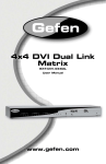
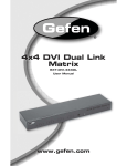
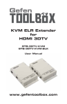
IR CAT-5
Extender
EXT-HDMIIR-CAT5
User Manual
www.gefen.com
f
ASKING FOR ASSISTANCE
Technical Support:
Telephone
Fax
(818) 772-9100
(800) 545-6900
(818) 772-9120
Technical Support Hours:
8:00 AM to 5:00 PM Monday thru Friday.
Write To:
Gefen Inc.
c/o Customer Service
20600 Nordhoff St
Chatsworth, CA 91311
www.gefen.com
[email protected]
Notice
Gefen Inc. reserves the right to make changes in the hardware, packaging and
any accompanying documentation without prior written notice.
HDMI CAT-5 IR Extender is a trademark of Gefen Inc.
© 2008 Gefen Inc., All Rights Reserved
All trademarks are the property of their respective companies
Rev X2
CONTENTS
1
Introduction
2
Operation Notes
3
Features
4
Sender Panel Layout
5
Sender Panel Descriptions
6
Receiver Panel Layout
7
Receiver Panel Descriptions
8
Connecting And Operating The HDMI CAT-5 IR Extender
9
Adjusting The HDMI CAT-5 IR Extender
12 Network Cable Wiring Diagram
13 Specifications
14 Warranty
INTRODUCTION
Congratulations on your purchase of the HDMI CAT-5 IR Extender. Your
complete satisfaction is very important to us.
Gefen
Gefen delivers innovative, progressive computer and electronics add-on solutions
that harness integration, extension, distribution and conversion technologies.
Gefen’s reliable, plug-and-play products supplement cross-platform computer
systems, professional audio/video environments and HDTV systems of all sizes
with hard-working solutions that are easy to implement and simple to operate.
The Gefen HDMI CAT-5 IR Extender
Extending state-of-the-art digital video displays, computer monitors and IR
control signals has never been easier.
Distances of up to 150 feet at 1080p resolution (300 feet at 1080i resolution)
are guaranteed to perform beautifully, giving you a reliable method of all-digital
extension while streamlining your installation cabling needs.
How It Works
At the A/V source end, you connect the HDMI CAT-5 IR Extender Sender
unit to your HDMI source and its IR blaster to your devices IR eye using the
supplied cables. At the remote end, your HDMI display connects to the HDMI
IR Extender’s Receiver unit. Two CAT-5 cables connect the Sender and the
Receiver units to each other, allowing for up to 300 feet of A/V source extension.
Power-cycle all equipment and you will experience remote HDTV extension with
full IR control of your HDMI source.
For a sleeker appearance of your A/V equipment and greater installation
flexibility, optional Gefen IR eye (EXT-RMT-EXTIR) can be used to completely
hide the HDMI IR Receiver.
Note: The HDMI CAT-5 IR Extender system is HDCP compliant.
1
OPERATION NOTES
READ THESE NOTES BEFORE INSTALLING OR
OPERATING THE HDMI CAT-5 IR EXTENDER
•
The maximum cable extension is 300 feet (91 meters) for video resolutions
of 1080i and below.
•
The maximum cable extension is 150 feet (45 meters) for video resolutions
of 1080p.
•
If EMI (Electromagnetic Interference) is present anywhere near the CAT-5,
CAT-5e or CAT-6 video cables it may be necessary to use shielded cables.
This is to prevent possible interference from degrading the video signal.
Using shielded cable, however, will reduce the maximum distance that the
cables can be extended.
•
Extensions under 130 feet (40 meters) can use Auto Equalization (Auto EQ)
which is on by default. Extensions over 130 feet (40 meters) will require you
to manually equalize your signal (see page 9).
•
IR repeater functionality is only from the receiving unit to the sending unit. IR
data cannot be transmitted from the sending unit to the receiving unit.
•
Each cable run must be one continuous run from one end to the other. No
splices or use of punch down blocks.
•
High quality Shielded CAT-6 cabling should be used for maximum
performance.
•
Do not use stranded or low/no skew cabling. Solid core cabling should be
used for maximum performance.
•
HDMI 1.2 Compliant and HDMI 1.3 Compatible
•
HDCP Compliant.
2
FEATURES
Features
•
Supports resolutions up to 1080p, 2K, and 1920 x 1200
•
Sends video up to 300 feet (1080i) / 150 feet (1080p) away
•
Small and Compact, easy to install
•
Improved compensation for cable skew
•
A/V signals are sent digitally over CAT-5 cable for zero signal loss
•
Eliminates equipment noise in the viewing environment
•
Extends any IR device
•
HDMI/HDCP Compliant
Package Includes
(1) HDMI CAT-5 IR Sender
(1) HDMI CAT-5 IR Receiver
(1) 6 Foot HDMI Cable (M-M)
(1) IR Blaster
(2) 5V DC Power Supplies
(1) Owner’s Manual
3
SENDER PANEL LAYOUT
Front Panel
1
2
Back Panel
3
4
5
4
6
SENDER PANEL DESCRIPTIONS
1
LED Power Indicator
This LED will become active once the included 5V DC power supply is properly
connected between the sender and an open wall power socket.
2
HDMI Input
This input will accept one HDMI source device that will be extended to the
receiver’s location.
3
5V DC Power Receptacle
This receptacle will require power from the included 5V DC power supply for
proper operation.
4
IR Out (Blaster)
The included IR transmitter (blaster) connects to this output port. The IR
blaster’s IR emitter will need to be placed on or near the IR receiver of a device
for proper relaying of commands from the receiver.
5
Video CAT-5 Port
This port is used to connect the sending and receiving units together for Video
traffic. Use a CAT-5, CAT-5e or CAT-6 cable. When field terminating cable
please adhere to the TIA/EIA-568-B specification (page 12).
6
DDC CAT-5 Port
This port is used to connect the sending and receiving units together for DDC
traffic. Use a CAT-5, CAT-5e or CAT-6 cable. When field terminating cable
please adhere to the TIA/EIA-568-B specification (page 12).
5
RECEIVER PANEL LAYOUT
Front Panel
1
2
3
4
Back Panel
5
6
6
7
8
RECEIVER PANEL DESCRIPTIONS
1
Equalization Adjustment
This Trim Pot is used to adjust the equalization that compensates for the
differences that are present in cable qualities and skews. Automatic equalization
(Auto EQ) is available and is set to on by default. Cable lengths that exceed 130
feet (40 meters) should not use Auto EQ.
2
Infrared (IR) Receiver
This IR receiver will relay IR commands from the receiving unit to the sending
unit for output to a IR transmitter (blaster) on a IR controllable device.
3
HDMI Input
This input will accept one HDMI source device that will be extended to the
receiver’s location.
4
LED Power Indicator
This LED will become active once the included 5V DC power supply is properly
connected between the sender and an open wall power socket.
5
Video CAT-5 Port
This port is used to connect the sending and receiving units together for Video
traffic. Use a CAT-5, CAT-5e or CAT-6 cable. When field terminating cable
please adhere to the TIA/EIA-568-B specification (page 12).
6
DDC CAT-5 Port
This port is used to connect the sending and receiving units together for DDC
traffic. Use a CAT-5, CAT-5e or CAT-6 cable. When field terminating cable
please adhere to the TIA/EIA-568-B specification (page 12).
7
Infrared (IR) Receiver Extension Port
This port will accept an optionally purchased IR extension cable (Gefen part#
EXT-RMT-EXTIR). This is useful for installations where the IR receiver, located
on the front panel (Item 2 on this page), is not in line-of-sight with the IR remote
control used to relay commands to the device at the sender’s location.
8
5V DC Power Receptacle
This receptacle will require power from the included 5V DC power supply for
proper operation.
7
CONNECTING AND OPERATING THE HDMI CAT-5 IR EXTENDER
How to Connect the HDMI CAT-5 IR Extender
1.
Connect a HDMI cable (supplied) between the HDMI source device’s output
and the HDMI CAT-5 IR Extender sending unit’s input.
2.
Optionally, connect the mini-plug from the included IR transmitter (blaster)
to the HDMI CAT-5 IR Extender sending unit. Remove the adhesive on the
IR blaster located on the opposite end of the cable. Place the IR blaster on
or near the IR receiver of the device that is intended for control by the IR
remote control at the receiver’s location.
3.
Connect the sending and receiving units together using a pair of CAT-5,
CAT-5e or CAT-6 cables. Use one cable to link the VIDEO ports together and
the other cable to link the DDC ports together.
NOTE: When field terminating cabling please adhere to the TIA/EIA-568-B
specifications (page 12). Please ensure that the cables are not crossed; i.e.
VIDEO to the DDC ports or DDC to the VIDEO ports.
4.
Connect a HDMI cable (user supplied) between the HDMI capable device’s
input (i.e. display) and the HDMI CAT-5 IR Extender receiving unit’s output.
5.
Connect both of the included 5V DC power supplies between the HDMI CAT5 IR Extender sending and receiving units and open wall power sockets.
6.
Initialize (power on) the output device (i.e. display) first and the source
device second.
IR Relay Feature
If the IR transmitter (blaster) is connected to a device, step 2 above, it will be
possible to relay IR commands from the receiver to the connected device at
the sender’s location. Simply point the connected device’s IR remote at the IR
receiver on the HDMI CAT-5 IR Extender receiving unit and it will relay all button
presses back to the sender and out though the IR transmitter (blaster). Ultimately,
this will allow the user to control a single device from the extended location.
8
ADJUSTING THE HDMI CAT-5 IR EXTENDER
Auto Equalization (Auto EQ)
The HDMI CAT5 Extender has advanced equalization circuitry to compensate
for the differences that are present in CAT-5 (CAT-5e or CAT-6) cable quality and
skew. Auto EQ is enabled by default. In some cases Auto EQ may not result in
an optimal video signal. If either of the two following conditions are experienced,
Auto EQ will have to be disabled and manual adjustment procedures will need to
be applied.
1.
The CAT-5, CAT-5e or CAT-6 cable length exceeds 130 feet (40 meters).
This distance estimate is based on high quality CAT-6 cabling. The actual
distance at which Auto EQ will operate is based on the cabling used.
2.
There is no video output from the HDMI CAT-5 IR Extender receiving unit
upon initialization of all connected devices.
Manual Equalization
Manual equalization uses two settings (Boost and Equalization) to produce
an optimal video signal. These two adjustment options will need to be jointly
adjusted as they are related to each other.
Setting Manual Equalization
Manual equalization is set by accessing a bank of 4 DIP switches on the
underside of the HDMI CAT-5 IR Extender receiving unit. The bank of 4 DIP
switches is located underneath a piece of metallic colored tape. Remove this
tape to expose the DIP switches. Only DIP switch 1 is used on this bank. DIP
switches 2 through 4 are not used. Auto EQ is on by default (DIP switch 1 is
OFF). To turn OFF Auto EQ and enter manual equalization mode, turn DIP switch
1 ON. Please see the illustration below.
Auto Equalization
Manual Equalization
ON
ON
OFF
OFF
1
2
3
1
4
9
2
3
4
ADJUSTING THE HDMI CAT-5 IR EXTENDER
Boost
The boost setting will affect the amount of pre-emphasis that will be applied to
the video signal. This setting is located on the HDMI CAT-5 IR Extender sending
unit and has 4 distinct strength settings. This setting is mainly related to the
distance of CAT-5, CAT-5e or CAT-6 cabling used but is also affected by the
quality and skew of the cabling. The boost settings are set using a bank of DIP
switches on the underside of the HDMI CAT-5 IR Extender sending unit. The
bank of 4 DIP switches is located underneath a piece of metallic colored tape.
Remove this tape to expose the DIP switches. Only DIP switches 1 and 2 are
used on this bank. DIP switches 3 and 4 are not used. The default position of all
DIP switches are OFF (no boost). Please see the table and illustration below for
configuration options.
Sender Dip Switch Settings
Setting
Switch 1
Switch 2
No Boost (Default)
OFF
OFF
Medium Boost
OFF
ON
High Boost
ON
OFF
Very Low Boost
ON
ON
No Boost (default)
Medium Boost
ON
ON
OFF
OFF
1 2 3 4
1 2 3 4
High Boost
Very Low Boost
ON
ON
OFF
OFF
1 2 3 4
1 2 3 4
Equalization
The equalization setting will tune the signal effectively eliminating any video
noise. This setting is located on the HDMI CAT-5 IR Extender receiving unit
in the form of a Trim Pot adjustment dial. To adjust the equalization follow the
instructions below.
1.
Insert a small flat head tool into the Trim Pot on the receiver unit.
2.
Turn the trim pot in a clockwise fashion until it comes to a stop. Do not force
the trim pot beyond this point. Doing so may break the trim pot.
3.
Slowly turn the trim pot counter-clockwise in millimeter increments until the
image stabilizes and all video noise is eliminated.
4.
Carefully remove the adjustment tool.
10
ADJUSTING THE HDMI CAT-5 IR EXTENDER
Adjustment Procedure
Please follow the steps below to manually adjust the equalization.
1.
Turn on manual equalization mode.
2.
Attempt to equalize the signal using the equalization Trim Pot on the
receiving unit. If video output is not visible or is unsatisfactory after rotating
the Trim Pot dial through it’s entire range proceed to step 3.
3.
Increase the boost setting using the DIP switches on the sending unit.
4.
Re-attempt to equalize the signal using the equalization Trim Pot on the
receiving unit with the new boost setting. If video output is still not visible
or is unsatisfactory after rotating the Trim Pot dial through it’s entire range
repeat steps 3 and 4 until the video output stabilizes and all video noise is
eliminated.
11
NETWORK CABLE WIRING DIAGRAM
Gefen has specifically engineered their products to work with the TIA/EIA-568-B
specification. Please adhere to the table below when field terminating cable for
use with Gefen products. Failure to do so may produce unexpected results and
reduced performance.
Pin
Color
1
Orange / White
2
Orange
3
Green / White
4
Blue
5
Blue / White
6
Green
7
Brown / White
8
Brown
12345678
CAT-5, CAT-5e, and CAT-6 cabling comes in stranded and solid core types.
Gefen recommends using solid core cabling. CAT-6 cable is also recommended
for best results.
Each cable run must be one continuous run from one end to the other. No splices
or use of punch down blocks.
12
SPECIFICATIONS
Single-Link Range ..................................................................... 1080p/1920x1200
Input Video Signal .................................................................................... 1.2V p-p
Input DDC Signal ............................................................................... 5V p-p (TTL)
HDMI Connector .................................................................. Type A 19-pin Female
Link Connector .............................................................................. RJ-45 Shielded
Power Supply .............................................................................................. 5V DC
Power Consumption ................................................. 10 Watts (maximum per unit)
Dimensions .......................................................................... 3.4 x 5.9 x 1.3 inches
Shipping Weight ............................................................................................ 4 lbs.
13
WARRANTY
Gefen warrants the equipment it manufactures to be free from defects in material
and workmanship.
If equipment fails because of such defects and Gefen is notified within two (2)
years from the date of shipment, Gefen will, at its option, repair or replace the
equipment, provided that the equipment has not been subjected to mechanical,
electrical, or other abuse or modifications. Equipment that fails under conditions
other than those covered will be repaired at the current price of parts and labor in
effect at the time of repair. Such repairs are warranted for ninety (90) days from
the day of reshipment to the Buyer.
This warranty is in lieu of all other warranties expressed or implied, including
without limitation, any implied warranty or merchantability or fitness for any
particular purpose, all of which are expressly disclaimed.
1.
Proof of sale may be required in order to claim warranty.
2.
Customers outside the US are responsible for shipping charges to and from
Gefen.
3.
Copper cables are limited to a 30 day warranty and cables must be in their
original condition.
The information in this manual has been carefully checked and is believed to
be accurate. However, Gefen assumes no responsibility for any inaccuracies
that may be contained in this manual. In no event will Gefen be liable for
direct, indirect, special, incidental, or consequential damages resulting from
any defect or omission in this manual, even if advised of the possibility of such
damages. The technical information contained herein regarding the features and
specifications is subject to change without notice.
14
Rev X2
20600 Nordhoff St., Chatsworth CA 91311
1-800-545-6900
818-772-9100
www.gefen.com
fax: 818-772-9120
[email protected]