1
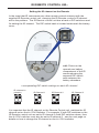
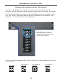
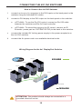
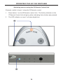
®
ASKING FOR ASSISTANCE
Technical Support:
Telephone
Fax
(818) 772-9100
(800) 545-6900
(818) 772-9120
Technical Support Hours:
8:00 AM to 5:00 PM Monday thru Friday.
Write To:
Gefen LLC
c/o Customer Service
20600 Nordhoff St
Chatsworth, CA 91311
www.gefen.com
[email protected]
Notice
Gefen LLC reserves the right to make changes in the hardware, packaging and
any accompanying documentation without prior written notice.
4x1 DVI Switcher is a trademark of Gefen LLC
© 2011 Gefen LLC, All Rights Reserved
All trademarks are the property of their respective owners
Rev A7
CONTENTS
1
Introduction
2
Operation Notes
3
Features
4
Front Panel Layout
5
Front Panel Descriptions
6
Back Panel Layout
7
Back Panel Descriptions
8
IR Remote Control Unit
8
Layout and Description
9
Installing the Battery
10
Setting the IR channel on the Remote
11
Setting the IR channel on the 4x1 DVI Switcher
12 Connecting the 4x1 DVI Switcher
12
Wiring Diagram
13 Operating the 4x1 DVI Switcher
13
Front Panel Buttons and LED Indicators
13
Switching sources using the front-panel buttons
14
Switching sources using the IR Remote Control Unit
15
Switching sources using RS-232
16 RS-232 Control
17 Specifications
18 Warranty
INTRODUCTION
Congratulations on your purchase of the Gefen 4x1 DVI Switcher. Your complete
satisfaction is very important to us.
Gefen
Gefen delivers innovative, progressive computer and electronics add-on solutions
that harness integration, extension, distribution and conversion technologies.
Gefen’s reliable, plug-and-play products supplement cross-platform computer
systems, professional audio/video environments and HDTV systems of all sizes
with hard-working solutions that are easy to implement and simple to operate.
The Gefen 4x1 DVI Switcher
The rack-mountable Gefen 4x1 DVI Switcher offers an economical solution by
eliminating the need to purchase many displays for each DVI source in a studio
or lab situation. A plug-and-play solution, the 4x1 DVI Switcher shares one DVI
display with up to four computers or other DVI video sources, saving space on
your desktop. The source computer is selected using the included IR remote
control or through RS-232 control.
How It Works
The DVI monitor is connected to the switcher’s output. Up to four DVI sources
connect to the switcher’s DVI inputs using included high quality DVI cables.
The included power supply is connected to the switcher via the locking power
plug and then to a power outlet. The currently selected computer’s video signal
appears on the shared monitor. Video sources are selected/switched using the
RMT-4IR remote control, RS-232 control, or the input selector push button on the
front panel of the switcher.
1
OPERATION NOTES
READ THESE NOTES BEFORE INSTALLING OR
OPERATING THE GEFEN 4X1 DVI SWITCHER
•
The 4x1 DVI Switcher will take any of up to four (4) DVI single-link resolution
inputs and switch them, one at a time, to a DVI output device such as a
display/monitor or projector. Resolutions up to 1920x1200 are supported.
•
The 4x1 DVI Switcher is housed in a metal box for better RF shielding.
•
Computers must be turned on one at a time and the Switcher must be
selected to the computer that is booting up. Afterwards, the Switcher can be
routed to any input.
2
FEATURES
Features
•
Switches easily between any four DVI sources
•
Maintains highest resolution single-link DVI at 1920x1200
•
Discrete IR remote control included
•
Serial RS-232 remote port for switching via automated control or PC
•
Supports DDWG standards for DVI monitors
Package Includes:
(1) 4x1 DVI Switcher
(4) 6 ft. DVI cables
(1) IR Remote Control Unit
(1) 5V DC Power Supply
(1) User Manual
3
1
2
3
Front Panel
4
FRONT PANEL LAYOUT
4
FRONT PANEL DESCRIPTIONS
1
Input Indicators (1 - 4)
Each of these LED indicators glows bright blue according to the current DVI
input selection (see Input Buttons, below)
2
IR
Receives IR signals from the included IR Remote Control Unit.
3
Input Buttons (1 - 4)
Pressing each of these buttons selects the desired DVI input source (1 - 4).
4
Power
This LED indicator will glow bright red when the unit is powered..
5
1
2
Back Panel
3
4
5
BACK PANEL LAYOUT
6
BACK PANEL DESCRIPTIONS
1
5V DC
Connect the included 5V DC locking power supply to this receptacle.
2
In 1 - In 4
Each of these ports will accept a DVI source device.
3
DVI Out
This port will accept a single DVI output device. The currently selected DVI
input source will be output via this port.
4
RS-232
This port is used for serial communication using an RS-232 control device. For
details, refer to page 16.
5
Ext IR
Connect an IR extender (Gefen part no. EXT-RMT-EXTIR) cable to this port.
7
IR REMOTE CONTROL UNIT
Layout and Description
1
2
1
Activity Indicator
This LED will be activated momentarily each time a button is pressed.
2
Source Selection Buttons (1 - 4)
These buttons are used to select which source is routed to a monitor.
NOTE: An Activity Indictor that flashes quickly while holding down
any one of the sixteen buttons indicates a low battery. Replace
the IR Remote Control battery as soon as possible.
8
IR REMOTE CONTROL UNIT
Installing the Battery
1.
Remove the battery cover on the back of the IR Remote Control Unit.
2.
Insert the included battery into the open battery slot. The positive (+) side of
the battery should be facing up.
3.
Replace the battery cover.
The Remote Control unit ships with two batteries. One battery is required for
operation and the other battery is a spare.
Battery Slot
WARNING: Risk of explosion if battery is replaced by an
incorrect type. Dispose of used batteries according to the
instructions.
9
IR REMOTE CONTROL UNIT
Setting the IR channel on the Remote
In the event that IR commands from other remote controls interfere with the
supplied IR Remote Control unit, changing the IR Remote Control’s IR channel
will fix the problem. The IR Remote Control unit has a bank of DIP switches used
for setting the IR channel. The DIP switch bank is located underneath the battery
cover.
Left: Picture of the
opened rear battery
compartment of the IR
remote showing the
exposed DIP Switch
bank between the
battery chambers.
Corresponding DIP Switch Settings for each IR Channel
IR Channel 0
(default)
IR Channel 1
ON
1
2
IR Channel 2
1
IR Channel 3
ON
ON
2
1
2
ON
1
2
It is important that the IR channel on the Remote Control unit, matches the IR
channel set on the 4x1 DVI Switcher. For example, if both DIP switches on the
IR Remote Control unit are set to IR channel 0 (both DIP switches down), then
the 4x1 DVI Switcher must also be set to IR channel 0. See the next page for
details on how to change the IR channel on the 4x1 DVI Switcher.
10
IR REMOTE CONTROL UNIT
Setting the IR channel on the 4x1 DVI Switcher
In order for the IR Remote Control Unit to communicate properly with the
Switcher, both the Remote and the Switcher must be set to the same IR channel.
The 4x1 DVI Switcher has a bank of eight (8) DIP switches on the bottom of the
unit. DIP switch 7 and 8 are used to set the IR channel for the Switcher. DIP
switches 1 - 6 are reserved for future expansion.
Left : DIP switch 7 and 8 on
the bottom of the Switcher.
These DIP switches are in the
default (OFF) position.
Use the following settings for DIP switch 7 and 8 to set the IR channel on the 4x1
DVI Switcher:
IR Channel 0
ON
7
8
IR Channel 1
IR Channel 2
ON
7
IR Channel 3
ON
8
7
11
8
ON
7
8
CONNECTING THE 4X1 DVI SWITCHER
How to Connect the 4x1 DVI Switcher
1
Connect up to four (4) computers to the DVI inputs on the back panel of the
Switcher using the included DVI cables.
2
Connect a DVI display to the DVI output on the back panel of the Switcher.
a
OPTIONAL: To use the RS-232 control, connect an RS-232 cable
between the Switcher and RS-232 host controller.
b
OPTIONAL: To extend the range of the IR control, connect an IR
Extender (Gefen part no. EXT-RMT-EXTIR) to the back of the Switcher.
3
Connect the included 5V locking power supply to the power receptacle on
the 4x1 DVI Switcher
4
Connect the AC power cord to an available electrical outlet.
Wiring Diagram for the 4x1 DisplayPort Switcher
DVI CABLE
Computer
Computer
Computer
uter
e
Computer
Switcher
DVI MONITOR
EXT-DVI-441N
EX
XT
ATTENTION: This product should always be connected to a
grounded electrical socket.
12
OPERATING THE 4X1 DVI SWITCHER
Front Panel Buttons and LED Indicators
The front panel of the 4x1 DisplayPort Switcher has a set of four (4) LED
indicators, displaying which input (source) is being displayed. Each of these LED
indicators corresponds to one of the push-buttons on the front panel.
Switching sources using the front-panel buttons
Example: Switch to input 3 using the front-panel buttons:
1
Press button 3 on the front panel of the 4x1 DisplayPort Switcher.
2
The LED indicator for input 3 will glow bright blue on the front panel.
1
2
13
OPERATING THE 4X1 DVI SWITCHER
Switching sources using the IR Remote Control Unit
Example: Switch to Input 1 using the IR Remote Control:
1
Press button 1 on the IR Remote Control Unit. The Activity Indicator on the
IT Remote Control Unit will glow yellow, indicating that a button was pressed.
2
The LED indicator for input 1 will glow bright blue.
1
2
14
OPERATING THE 4X1 DVI SWITCHER
Switching sources using RS-232
Configure the Switch for use with RS-232 (see page 14 for details).
Example: Switch to input 4 using RS-232
1
Type 4 then press the Enter key to route the Switcher to Input 4. See page
15 for additional information on RS-232 commands.
2
The LED indicator for Input 4 will glow bright green on the front panel.
1
terminal ready...
4
Route to Input 4
2
15
RS-232 CONTROL
Only pins 2 (Receive), 3 (Transmit), and 5 (Ground) are used for communication.
A null-modem adapter should not be used with this product.
54321
12345
9876
6789
Only Pins 2 (RX), 3 (TX), and 5 (Ground) are used on the RS-232 serial interface
Serial Port Settings
Bits per second ............................................................................................ 19200
Data bits ............................................................................................................... 8
Parity ............................................................................................................. None
Stop bits ................................................................................................................1
Flow Control .................................................................................................. None
NOTE: Only pins 2 (Receive), 3 (Transmit), and 5 (Ground) are
used for communication. A null-modem adapter should nott be
used with this product.
16
SPECIFICATIONS
Maximum Pixel Clock................................................................................165 MHz
Input Video Signal................................................................................1.2 Volts p-p
Input DDC Signal...........................................................................5 Volts p-p (TTL)
DVI Input Connectors......................................(4) DVI-I 29-pin female (digital only)
DVI Output Connectors...................................(1) DVI-I 29-pin female (digital only)
RS-232 Connector.........................................................................(1) DB-9, female
IR Extender Connector........................................................ (1) 3.5 mm mini-stereo
Power Supply................................................................................................5 V DC
Power Consumption........................................................................10 Watts (max.)
Dimensions..........................................................................14” W x 1.2” H x 2.9” D
Shipping Weight..............................................................................................7 lbs.
17
WARRANTY
Gefen warrants the equipment it manufactures to be free from defects in material
and workmanship.
If equipment fails because of such defects and Gefen is notified within two (2)
years from the date of shipment, Gefen will, at its option, repair or replace the
equipment, provided that the equipment has not been subjected to mechanical,
electrical, or other abuse or modifications. Equipment that fails under conditions
other than those covered will be repaired at the current price of parts and labor in
effect at the time of repair. Such repairs are warranted for ninety (90) days from
the day of reshipment to the Buyer.
This warranty is in lieu of all other warranties expressed or implied, including
without limitation, any implied warranty or merchantability or fitness for any
particular purpose, all of which are expressly disclaimed.
1.
Proof of sale may be required in order to claim warranty.
2.
Customers outside the US are responsible for shipping charges to and from
Gefen.
3.
Copper cables are limited to a 30 day warranty and cables must be in their
original condition.
The information in this manual has been carefully checked and is believed to
be accurate. However, Gefen assumes no responsibility for any inaccuracies
that may be contained in this manual. In no event will Gefen be liable for
direct, indirect, special, incidental, or consequential damages resulting from
any defect or omission in this manual, even if advised of the possibility of such
damages. The technical information contained herein regarding the features and
specifications is subject to change without notice.
For the latest warranty coverage information, refer to the Warranty and Return
Policy under the Support section of the Gefen Web site at www.gefen.com.
PRODUCT REGISTRATION
Please register your product online by visiting the Register Product page
under the Support section of the Gefen Web site.
18
Rev A7
This product uses UL listed power supplies.


![LS5105 Document No 2 [PDF 1MB] - Australian Electoral Commission](http://vs1.manualzilla.com/store/data/005655823_1-2458abda02bbd8390d0ac9ba8bd86ac6-150x150.png)