1
9XCite‐PKG‐R™ RS‐232/485 RF Modem – Product Manual v2.1 [2007.01.04]
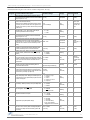
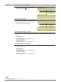
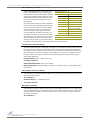
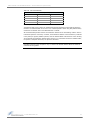
Table 4‐02.
Non‐AT Settable Parameters
(Settable/Readable using the X‐CTU Software “Modem Configuration” tab only)
AT
Designator
Command Name & Description
Parameter Range
Command
Category
# Bytes
Factory
Returned Default
AT
Guard Time After. Set required DI pin silent time after the
Command Sequence Characters of the AT Command Mode
Sequence (BT+ CC + AT).
0x02 – 0xFFFF
[x 1 ms]
AT Command
Mode Options
2
0x1F4
(500d)
BD
Interface Data Rate. Set serial data rate (baud rate at which
radio modem interfaces with host).
0–6
Serial data rate is different than RF data rate which is fixed
(1200 - 57600 bps)
and factory-set. If the serial data rate is set higher than RF
data rate, flow control may need to be observed to prevent DI
buffer overrun.
Serial
Interfacing
1
Set to equal
radio modem’s
fixed RF data
rate.
BI
Number of Bits. (7 or 8) – Sets number of data bits per
character (bits between start and stop bits).
Serial
Interfacing
1
1
BT
Guard Time Before. Set required DI pin silent time before the
0 – 0xFFFF
Command Sequence Characters of the Command Mode
[x 1 ms]
Sequence (BT+ CC + AT).
AT Command
Mode Options
2
0x1F4
(500d)
CC
Command Sequence Character. Set the ASCII character to be
used between Guard Times of the AT Command Mode
Sequence (BT+ CC + AT). The AT Command Mode Sequence 0x20 – 0x7F
enters the radio modem to AT Command Mode (from Idle
Mode).
AT Command
Mode Options
1
0x2B
(plus sign (+) in
ASCII)
CT
Time before Exit AT Command Mode. Set time period of
inactivity (no valid commands received) after which radio
modem automatically exits from AT Command Mode.
AT Command
Mode Options
2
0xC8
(200d)
FL
Software Flow Control. Enable serial software flow control on 0 - 1
the radio modem. (Hardware flow control (CTS ) is on by
0 = disable
default.)
1 = enabled
Serial
Interfacing
1
0
HT
Time before Wake-up Initializer. Set time period of inactivity
(no serial or RF data is sent or received) before a Wake-up
Initializer is sent. Base station tracks awake-status of remote
radios. HT of base radio should be set shorter than ST of
remote radios.
0 – 0xFFFF
[x 100 ms]
Sleep
(Low Power)
2
0xFFFF
(no wake-up
Initializer will be
sent)
ID
Modem VID. Read radio modem VID (Vendor Identification
Number). Only radio modems with matching VIDs can
communicate with each other.
0 – 0x7FFF
(above this range is Read-only)
Networking
2
0x3332
LH
Wake-up Initializer Time. Set time of the Wake-up Initializer
used to wake remote radios that are in cyclic sleep mode.
Time of Wake-up Initializer should be longer than that of the
remote radio’s cyclic sleep cycle (SM 3 - 8).
0 – 0xFF
[x 100 ms]
Sleep
(Low Power)
1
1
NB
Parity. Select parity format. Settings 0-4 transfer only 8 bits
out the antenna port and generate the parity bit on the radio
modem receiving side.
0–4
0 = 8-none-1, 7-any-1
1 = 8-even-1
2 = 8-odd-1
3 = 8-mark-1, 8-none-2
4 = 8-space-1
Serial
Interfacing
1
0
PW
Pin Wake-up. Enable pin wake-up from Cyclic Sleep Mode.
0–1
0 = disabled
1 = enabled
Sleep
(Low Power)
1
0
RT
DI2 Configuration. Enable RTS Mode
0-1
0 = Disabled
1 = RTS flow control
Serial
Interfacing
1
0
SB
Stop Bits. Set number of stop bits.
0–1
0 = 1 stop bit
1 = 2 stop bits
Serial
Interfacing
1
0
SM
Sleep Mode. Specify Sleep Mode settings.
0–8
0 = No sleep
Sleep
1 = Pin Sleep
(Low Power)
2 = Serial Port Sleep
3 to 8 = Cyclic intervals
ranging from 0.5 to16.0 seconds
1
0
ST
Time before Sleep. Set time period of inactivity (no serial or
RF data is sent or received) before activating Sleep Mode.
Use with Cyclic Sleep and Serial Port Sleep [refer to SM
Command]
0x10 – 0xFFFF
[x 100 ms]
2
0x64
(100d)
© 2007 MaxStream, Inc.
0–1
0 = 7 bits
1 = 8 bits
0x02 – 0xFFFF
[x 100 ms]
Sleep
(Low Power)
21