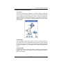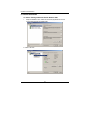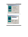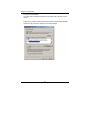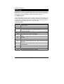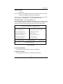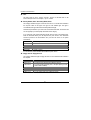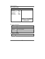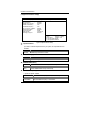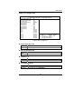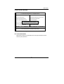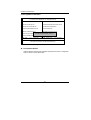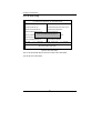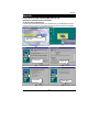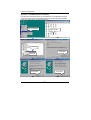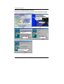
1
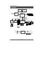
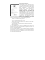
FCC Compliance Statement: This equipment has been tested and found to comply with limits for a Class B digital device, pursuant to Part 15 of the FCC rules. These limits are designed to provide reasonable protection against harmful interference in residential installations. This equipment generates, uses, and can radiate radio frequency energy, and if not installed and used in accordance with the instructions, may cause harmful interference to radio communications. However, there is no guarantee that interference will not occur in a particular installation. If this EricLu equipment does cause interference to radio or television equipment reception, which can be determined by turning the equipment off and on, the user is encouraged to try to correct the interference by one or more of the following measures: DECLARATION OF CONFORMITY Per FCC Part 2 Section 2. 1077(a) Responsible Party Name: G.B.T. INC. Address: 18305 Valley Blvd., Suite#A LA Puent, CA 91744 Phone/Fax No: (818) 854-9338/ (818) 854-9339 hereby declares that the product Product Name: Mother Board Model Number: GA-6VTXDR-C Conforms to the following specifications: FCC Part 15, Subpart B, Section 15.107(a) and Section 15.109(a), Class B Digital Device Supplementary Information: This device complies with part 15 of the FCC Rules. Operation is subject to the following two conditions: (1) This device may not cause harmful and (2) this device must accept any inference received, including that may cause undesired operation. Representative Person's Name: ERIC LU Signature: Date: Sep. 07, 2001 -Reorient or relocate the receiving antenna -Move the equipment away from the receiver -Plug the equipment into an outlet on a circuit different from that to which the receiver is connected -Consult the dealer or an experienced radio/television technician for additional suggestions You are cautioned that any change or modifications to the equipment not expressly approve by the party responsible for compliance could void Your authority to operate such equipment. This device complies with Part 15 of the FCC Rules. Operation is subjected to the following two conditions 1) this device may not cause harmful interference and 2) this device must accept any interference received, including interference that may cause undesired operation. Declaration of Conformity We, Manufacturer/Importer (full address) G.B.T. Technology Träding GMbH Ausschlager Weg 41, 1F, 20537 Hamburg, Germany declare that the product ( description of the apparatus, system, installation to which it refers) Mother Board GA-6VTXDR-C is in conformity with (reference to the specification under which conformity is declared) in accordance with 89/336 EEC-EMC Directive EN 55011 Limits and methods of measurement of radio disturbance characteristics of industrial, scientific and medical (ISM high frequency equipment EN 61000-3-2* EN60555-2 Disturbances in supply systems caused by household appliances and similar electrical equipment “Harmonics” EN55013 Limits and methods of measurement of radio disturbance characteristics of broadcast receivers and associated equipment EN61000-3-3* EN60555-3 Disturbances in supply systems caused by household appliances and similar electrical equipment “Voltage fluctuations” EN 55014 Limits and methods of measurement of radio disturbance characteristics of household electrical appliances, portable tools and similar electrical apparatus EN 50081-1 Generic emission standard Part 1: Residual, commercial and light industry EN 50082-1 Generic immunity standard Part 1: Residual, commercial and light industry EN 55015 Limits and methods of measurement of radio disturbance characteristics of fluorescent lamps and luminaries EN 55081-2 Generic emission standard Part 2: Industrial environment EN 55020 Immunity from radio interference of broadcast receivers and associated equipment EN 55082-2 Generic immunity standard Part 2: Industrial environment EN 55022 Limits and methods of measurement of radio disturbance characteristics of information technology equipment ENV 55104 Immunity requirements for household appliances tools and similar apparatus DIN VDE 0855 part 10 part 12 Cabled distribution systems; Equipment for receiving and/or distribution from sound and television signals EN 50091- 2 EMC requirements for uninterruptible power systems (UPS) CE marking (EC conformity marking) The manufacturer also declares the conformity of above mentioned product with the actual required safety standards in accordance with LVD 73/23 EEC EN 60065 Safety requirements for mains operated electronic and related apparatus for household and similar general use EN 60950 Safety for information technology equipment including electrical business equipment EN 60335 Safety of household and similar electrical appliances EN 50091-1 General and Safety requirements for uninterruptible power systems (UPS) Manufacturer/Importer (Stamp) Date : Sep. 07, 2001 Signature : Rex Lin Name : Rex Lin 6VTXDR-C Socket 370 Dual Processors Motherboard USER'S MANUAL Socket 370 Dual Processors Motherboard REV. 1.0 First Edition 12ME-6VTXDRC-1001 How This Manual Is Organized This manual is divided into the following sections: 1) Revision History Manual revision information 2) Item Checklist Product item list 3) Features Product information & specification 4) Hardware Setup Instructions on setting up the motherboard 5) Performance & Block Diagram Product performance & block diagram 6) Advanced Networking Services Advanced Networking Services for Windows NT* 4 and Windows 2000 (Teaming) 7) BIOS Setup Instructions on setting up the BIOS software 8) Technical Support/RMA Sheet Document equipment used for after sales service 9) Appendix General reference Table Of Content Revision History P.1 Item Checklist P.2 Features Summary P.3 6VTXDR-C Motherboard Layout P.5 Installation Guide P.6 Page Index for Connectors/Panel and Jumper Definition P.12 Performance List P.28 Block Diagram P.29 Advanced Networking Services for Windows NT* 4 and Windows 2000 (Teaming) P.30 Page Index for BIOS Setup P.36 Technical Support / RMA Sheet P.63 Appendix P.64 6VTXDR-C Motherboard Revision History Revision 1.0 Revision Note Initial release of the 6VTXDR-C motherboard user’s manual. Date Sep. 2001 The author assumes no responsibility for any errors or omissions that may appear in this document nor does the author make a commitment to update the information contained herein. Third-party brands and names are the property of their respective owners. Sep. 20, 2001 Taipei, Taiwan, R.O.C 1 Item Checklist Item Checklist The 6VTXDR-C motherboard Cable for IDE / floppy device Diskettes or CD (Driver CD) for motherboard driver & utility 6VTXDR-C user’s manual Internal COM B Cable (Optional) 2 6VTXDR-C Motherboard Features Summary Form Factor CPU Chipset Clock Generator Memory I/O Control Slots On-Board IDE On-Board Peripherals On-Board VGA On-Board LAN 30.5 cm x 24.8 cm ATX size form factor, 6 layers PCB. 2 Socket 370 processor Supports all new Pentium III processors (FC-PGA & FC-PGA2 package) Supports100/133MHz system bus frequency Can’t Support processor with Vcore above 1.8V L2 cache in CPU (Depend on CPU) VT82C694T (VIA Apollo Pro 133T) VT82C686B, Rev C ICS 9248AF-63 100/133 MHz system bus speeds (PCI 33MHz) 4 168-pin DIMM sockets Support PC-100 / PC-133 SDRAM and VCM SDRAM Support up to 4GB DRAM (Max) Support only 3.3V SDRAM DIMM Support 72bit ECC type DRAM integrity mode Support registered or un-buffered DRAM VT82C686B,Rev C 5 PCI slot supports 33MHz & PCI 2.2 compliant 1 AMR (Audio Modem Riser) slot IDE 1and IDE 2 Support PIO mode 3, 4, UDMA 33 / ATA 66 IDE & ATAPI CD-ROM IDE 3 and IDE 4 Compatible with RAID, Ultra ATA/100, Ultra ATA/66, UDMA 33, EIDE 4 IDE bus master IDE ports for up to 8 ATAPI devices 1 floppy port supports 2 FDD with 360K, 720K, 1.2M, 1.44M and 2.88M bytes 1 parallel ports supports Normal/EPP/ECP mode 1 serial ports (COM 1) 4 USB ports 1 IrDA connector for Fast IrDA Onboard AGP ATI RAGE XL 2X Onboard INTEL 82559 Ethernet To be continued… 3 Features Summary On-Board RAID Hardware Monitor PS/2 Connector BIOS Additional Features Support data striping (RAID 0) or mirroring (RAID 1), striping/mirroring (RAID 0+1) or spanning (JBOD) operation.. Support concurrent dual IDE controller operation. Support IDE bus master operation. Displays status and error checking messages during boot-up. Mirroring supports automatic background rebuilds Feature LBA and Extended Interrupt13 drive translation in controller onboard BIOS. CPU / Power / System fan revolution detect CPU / Power / System temperature detect System voltage detect CPU overheat shutdown detect PS/2 Keyboard interface and PS/2 Mouse interface Licensed AMI BIOS, 4M bits flash ROM Support Wake-On-LAN (WOL) Support Internal / External Modem Ring On Includes 5 fan power connectors Poly fuse for keyboard over-current protection 4 6VTXDR-C Motherboard 6VTXDR-C Motherboard Layout ATX Power PS/2 J15 J20 JP3 USB PGA 370 CPU 2 VGA LPT COM 1 J16 VT82C694T PGA 370 CPU 1 82559 J13 INTEL DIMM4 DIMM3 DIMM2 DIMM1 LAN1 Conn. SW1 6VTXDR-C PCI1 JP5 AMR USB2 JP10 JP1 J2 PCI5 J3 COM2 J4 BAT1 BZ1 J1 JP2 5 J14 PCI4 JP7 JP11 IDE4 IDE3 J19 ATA-100 VT82C686B BIOS Promise JP4 PCI3 IDE2 PCI2 IDE1 Floppy ATI Rage Installation Guide Installation Guide Getting Started WARNING! 1. 2. 3. 4. 5. Computer motherboards and expansion cards contain very delicate Integrated Circuit (IC) chips. To protect them against damage from static electricity, you should follow some precautions whenever you work on your computer. Unplug your computer when working on the inside. Use a grounded wrist strap before handling computer components. If you do not have one, touch both of your hands to a safely grounded object or to a metal object, such as the power supply case. Hold components by the edges and try not touch the IC chips, leads or connectors, or other components. Place components on a grounded antistatic pad or on the bag that came with the components whenever the components are separated from the system. Ensure that the ATX power supply is switched off before you plug in or remove the ATX power connector on the motherboard. Installing the motherboard to the chassis… If the motherboard has mounting holes, but they don’t line up with the holes on the base and there are no slots to attach the spacers, do not become alarmed you can still attach the spacers to the mounting holes. Just cut the bottom portion of the spacers (the spacer may be a little hard to cut off, so be careful of your hands). In this way you can still attach the motherboard to the base without worrying about short circuits. Sometimes you may need to use the plastic springs to isolate the screw from the motherboard PCB surface, because the circuit wire may be near by the hole. Be careful, don’t let the screw contact any printed circuit write or parts on the PCB that are near the fixing hole, otherwise it may damage the board or cause board malfunctioning. 6 6VTXDR-C Motherboard To set up your computer, you must complete the following steps: Step 1 - Set system jumpers Step 2- Install the Central Processing Unit (CPU) Step 3-Install memory modules Step 4-Install expansion cards (Optional) Step 5-Connect ribbon cables, cabinet wires, and power supply Step 6-Set up BIOS software Step 7-Install supporting software tools Step 3 Step 2 Step 5 Step 1 Step 5 Step 4 7 Installation Guide CPU Speed Setup The system bus speed is depended on CPU. (Supported 100,133MHz). The user can change the DIP switch (SW1) selection to set up the CPU speed for 500MHz – 1GHz processor. SW1 (RATIO): FREQ. RATIO X3 X3.5 X4 X4.5 X5 X5.5 X6 X6.5 X7 X7.5 X8 X8.5 X9 X9.5 X10 X10.5 X11 X11.5 X12 X13 X14 X15 X16 O : ON, X : OFF DIP SWITCH 1 2 3 4 O X O X O X O X O X O O X X X O O X O X O X O X X O O X X O O X X O X X O O O X O X X O O X O O X X X X O O O O X O O O X X X X X X O O O O O O O O O X X X X X O O O X O X O O O X X X ON 1 2 3 4 You can change the DIP switch (SW1) selection to set up the CPU Speed. The CPU frequency RATIO is 5. The FSB is 100MHz, than CPU speed is 500MHz. The FSB is 133MHz, than CPU Speed is 667MHz. SW2 SW1 8 6VTXDR-C Motherboard The CPU speed must match with the frequency ratio. It will cause system hanging up if the frequency ratio is higher than that of CPU. For dual CPU use, the same CPU must be used in CPU socket1 and 2. (The same stepping, FSB, ratio) Intel Processor all have locked Frequency Multiple, so you can not change the CPU Frequency Multiple. CPU Installation Please make sure the CPU type and speed is supported by your motherboard. For example: The newest Pentium III processor (FC-PGA2 package). CPU Top View CPU Bottom View Socket Actuation Lever 1.Pull the lever out and lift it up. Blank 2.The notched corner should point toward the end of the lever. The CPU will only fit in the orientation as shown. 9 Installation Guide CPU Heat Sink Installation: Beware: Please check that the heat sink is in good contact with the CPU before you turn on your system. Poor contact will cause over heat with might cause damage to your processor! 3.Align CPU and insert it (Please refer to your heatsink installation manual for application of thermal grease to provide better heat conduction between your CPU and heatsink.) 4.Use compliant fan approved by Intel. 5.Hook one end of the cooler bracket to the CPU socket. 6. Hook the other end of the cooler bracket to the CPU socket. 7. Make sure the CPU fan is plugged to the CPU fan connector, than install complete. (Please refer to the cooler’s installation manual for detailed installation steps) 10 6VTXDR-C Motherboard Memory Installation The motherboard has 4 dual inline memory module (DIMM) sockets support 4 banks. The BIOS will automatically detects memory type and size. To install the memory module, just push it vertically into the DIMM Slot .The DIMM module can only fit in one direction due to the two notch. Memory size can vary between sockets. SDRAM 1. The DIMM slot has two notch, so the DIMM 2. Insert the DIMM memory module vertically memory module can only fit in one direction. into the DIMM slot. Then push it down. 3. Close the plastic clip at both edges of the DIMM slots to lock the DIMM module. Reverse the installation steps when you wish to remove the DIMM module. Install memory in any combination table: DIMM DIMM 1 DIMM 2 DIMM 3 DIMM 4 168-pin SDRAM DIMM Modules Supports 16 / 32 / 64 / 128 / 256 / 512 MB / 1GHz Supports 16 / 32 / 64 / 128 / 256 / 512 MB / 1GHz Supports 16 / 32 / 64 / 128 / 256 / 512 MB / 1GHz Supports 16 / 32 / 64 / 128 / 256 / 512 MB / 1GHz ★Total System Memory (Max 4GB) 11 X 1 pcs X 1 pcs X 1 pcs X 1 pcs Installation Guide Page Index for Connectors/Panel and Jumper Definition Connectors ATX Power COM 1 / VGA / LPT Port Floppy Port IDE 1(Primary) / IDE 2(Secondary) Port / IDE3,IDE4 Port J1 (Wake On LAN) J3 (Ring Power On) J4 (IR) J13 CPU FAN 1 J14 Panel FAN J15 CPU FAN 2 J16 Power FAN 1 J20 Power FAN 2 LAN connector PS/2 Keyboard & PS/2 Mouse Connector USB 1 Connector USB 2 Connector COM 2 SMBUS Panel and Jumper Definition J2 (2x11 Pins Jumper) J19 (Panel LED Connector) JP1 (Clear CMOS Function) JP2 (Case Open) JP3 (USB Device Wake Up Selection) JP4 (Onboard AGP Selection) JP5 (Onboard LAN1 Selection) JP7 (BIOS Flash ROM Write Protect)[Optional] JP10 (IDE RAID Selection) BAT1 (Battery) 12 Page P.13 P.17 P.13 P.18 P.18 P.19 P.19 P.20 P.15 P.17 P.15 P.16 P.16 P.14 P.14 P.13 P.20 P.21 P.21 P.22 P.22 P.26 P.23 P.25 P.24 P.25 P.24 P.23 P.26 P.27 6VTXDR-C Motherboard Connectors COM 1 / VGA / LPT Port LPT PORT COM 1 VGA Please note: This mainboard supports 1 standard COM port, 1 VGA port and 1 LPT port. Devi like printer can be connected to LPT port ; mouse and modem etc can be connected to COM port. USB 1 Connector 1 2 3 4 5 67 8 Pin No. 1 2 3 4 5 6 7 8 Definition USB Power USB D0USB D0+ GND USB Power USB D1USB D1+ GND Please note: Before you connect your device(s) into USB connector(s), please make sure your device(s) such as USB keyboard, mouse, scanner, zip, speaker..etc. have a standard USB interface. Also make sure your OS (Win 95 w/ USB supperment, Win98, Windows 2000, Windows ME, Win NT w/ SP 6) supports USB controller. If your OS does not support USB controller, please contact OS vendor for possible patch or driver upgrade. For more information please contact your OS or device(s) vendors. 13 Connectors PS/2 Keyboard & PS/2 Mouse Connector PS/2 Mouse PS/2 Mouse/ Keyboard Pin No. Definition 1 Data 2 NC 3 GND 4 Power 5 Clock 6 NC 5 6 3 4 1 2 PS/2 Keyboard Please note: This mainboard supports standard PS/2 keyboard and PS/2 mouse interface connector. LAN Connector LAN1 1 2 (LAN Active LED) 1 – Yellow LED (LAN Active LED) 2 – Green LED (LAN Link LED) 14 6VTXDR-C Motherboard J13 : CPU Fan 1 1 Pin No. Definition 1 Control 2 +12V 3 SENSE Please note, a proper installation of the CPU cooler is essential to prevent the CPU from running under abnormal condition or damaged by overheating. J15 : CPU Fan 2 1 Pin No. Definition 1 Control 2 +12V 3 SENSE Please note, a proper installation of the CPU cooler is essential to prevent the CPU from running under abnormal condition or damaged by overheating. 15 Connectors J16 : Power Fan 1 1 Pin No. Definition 1 Control 2 +12V 3 SENSE J20 : Power Fan 2 1 Pin No. Definition 1 Control 2 +12V 3 SENSE 16 6VTXDR-C Motherboard J14 : Panel Fan 1 Pin No. Definition 1 Control 2 +12V 3 SENSE ATX Power 20 11 1 10 Pin No. Definition 3,5,7,13, GND 15-17 1,2,11 3.3V 4,6,19,20 VCC 10 +12V 12 -12V 18 -5V 8 Power Good 9 5V SB stand by+5V 14 PS-ON(Soft On/Off) Please note: AC power cord should only be connected to your power supply unit after ATX power cable and other related devices are firmly connected to the mainboard. 17 Connectors Floppy Port Red Line FDD1 IDE1 (Primary), IDE2 (Secondary), IDE3/IDE4(ATA100 or IDE RAID) Red Line IDE1 IDE2 IDE3 IDE4 18 6VTXDR-C Motherboard J3 : Ring Power On (Internal Modem Card Wake Up) 1 Pin No. Definition 1 Signal 2 GND J1 : Wake On LAN 1 Pin No. Definition 1 +5V SB 2 GND 3 Signal 19 Connectors J4 : IR 1 Pin No. Definition 1 VCC (+5V) 2 NC 3 IR Data Input 4 GND 5 IR Data Output Please note: Be careful with the polarity of the IR connector while you connect the IR. Please contact you nearest dealer for optional IR device. USB 2 Connector 2 10 1 9 Pin No. Definition 1,10 2,9 3 4,7 5 6 8 +5V GND USB D2NC USB D2+ USB D3+ USB D3- Please note: Be careful with the polarity of the front panel USB connector. Check the pin assignment while you connect the front panel USB cable. Please contact your nearest dealer for optional front panel USB cable. 20 6VTXDR-C Motherboard COM 2 2 10 1 9 COM 2 SM BUS 1 Pin No. 1 2 3 4 5 21 Definition SMB CLK NC GND SMB DATA +5V Panel and Jumper Definition Panel And Jumper Definition J2 : 2x11 Pins Jumper SPK GN RE GD 1 1 HD GN (Green Switch) GD (Green LED) HD (IDE Hard Disk Active LED) SPK (Speaker Connector) RE (Reset Switch) P+P−P−(Power LED) PW (Soft Power Connector) 1 P− P− P+ PW Open: Normal Operation Close: Entering Green Mode Pin 1: LED anode(+) Pin 2: LED cathode(−) Pin 1: LED anode(+) Pin 2: LED cathode(−) Pin 1: VCC(+) Pin 2- Pin 3: NC Pin 4: Data(−) Open: Normal Operation Close: Reset Hardware System Pin 1: LED anode(+) Pin 2: LED cathode(−) Pin 3: LED cathode(−) Open: Normal Operation Close: Power On/Off Please note, Please connect the power LED, PC speaker, reset switch and power switch etc of your chassis front panel to the front panel jumper according to the pin assignment above. 22 6VTXDR-C Motherboard JP1 : Clear CMOS Function 1 1 Clear CMOS Normal (Default) Pin No. Definition 1-2 Close Normal (Default) 2-3 Close Clear CMOS Please note, You may clear the CMOS data to its default values by this jumper JP7 : BIOS Flash ROM Write Protect (Optional) 1 1 Normal (Default) Pin No. Close Open Write Protection Definition BIOS Write Protection Normal (Default) Please note, To flash/upgrade BIOS on this MB JP7 must be set to open. We recommend JP7 to be set to “close”, whenever user does not need to flash/upgrade the BIOS. 23 Panel and Jumper Definition JP3 : USB device Wake up Selection 1 1 Normal (Default) Enable Pin No. Definition 1-2 close Normal (Default) Enabled USB Device 2-3 close Wake up Please note: To use “USB KB/MS Wakeup from S3” function, set BIOS setting “USB KB/MS Wake up from S3” to ENABLED and enable jumpers JP3. *(Power on the computer and as soon as memory counting starts, press <Del>. You will enter BIOS Setup. Select the item “POWER MANAGEMENT SETUP”, then select “USB KB/MS Wake up from S3”. Remember to save the setting by pressing "ESC" and choose the “SAVE & EXIT SETUP” option.) JP5 : Onboard LAN1 Selection 1 Enabled (Default) 1 Disabled Pin No. Definition Onboard LAN1 1-2 close Enabled Onboard LAN1 2-3 close Disabled Please note: This MB supports optional LAN chip.If the MB has optional LAN chip the user can enable the LAN function by setting the JP 5 to 1-2, user can disable the optional LAN function by setting the JP 5 to 2-3. JP 5 will have any effect if the board does not have optioal LAN chip 24 6VTXDR-C Motherboard JP4 : Onboard AGP Selection 1 1 Enabled (Default) Pin No. Open Close Disabled Definition Onboard AGP Disabled Onboard AGP Enabled JP2 : Case Open 1 Pin No. 1 2 3 25 Definition Signal GND NC Panel and Jumper Definition JP10 : IDE RAID Selection 1 1 Enabled (Default) Disabled Pin No. Definition 1-2 close IDE Raid Disabled 2-3 close IDE Raid Enabled J19 : Panel LED Connector 20 2 10 1 Pin No. 1-2 3-4 5-6 7-8 9 10 Definition CPU FAN1 CPU FAN2 SYSTEM FAN SYSTEM EVENT LAN1 Active LAN1 Link 11-12 13 14 15-16 17-18 LAN1 Speed LAN2 Active LAN2 Link LAN2 Speed Power LED 19-20 Power Button 26 6VTXDR-C Motherboard BAT1 : Battery + CAUTION Danger of explosion if battery is incorrectly replaced. Replace only with the same or equivalent type recommended by the manufacturer. Dispose of used batteries according to the manufacturer’s instructions. 27 Performance List Performance List The following performance data list is the testing results of some popular benchmark testing programs. These data are just referred by users, and there is no responsibility for different testing data values gotten by users. (The different Hardware & Software configuration will result in different benchmark testing results.) • CPU Intel Pentium III Processor 1260MHz x 2 (Taulatin) • DRAM 128MB*2 (KingMax PC-150) • CACHE SIZE 512KB include in CPU • DISPLAY Onboard ATI Rage XL 2X • STORAGE Onboard Promise RAID (Quantum AS30000AT 30GBx2) • O.S. Windows 2000 + SP2 • DRIVER Display Driver at 1024x768x16bitx75MHz (VUCD 1.81) ® Processor WCPUID 3.0C Clock Frequency Intel® Pentium III Processor 1260MHz*2 1260MHz(133x9.5) Top Performance BIOS Default CPU1 CPU2 CPU1 CPU2 Internal MHz 1262.33 1262.39 1262.38 1262.36 External MHz 132.88 132.88 132.88 132.88 SiSoft Sandra 20001 CPU/FPU Benchmark CPU Multi-Media Benchmark 7117/3363 5641/3361 13817/17158 13817/17158 Drivers Benchmark 32231 28954 Memory Benchmark 360/386 343/369 CC Winstone 2001 70.3 69.4 Business Winstore 2001 52.4 51.5 Winstone 2001 28 6VTXDR-C Motherboard Block Diagram CPUCLK (100/133MHz) PGA370 CPU PGA370 CPU System Bus 100/133MHz AGPCLK (66MHz) Ati Rage XL 2X AGP AGP VIA VT82C694T 3.3V SDRAM 100/133MHz HCLK (100/133MHz) AGPCLK (66MHz) 33MHz PCI Bus 33MHz 14.318MHz 48MHz Promise PDC20267 VIA VT82C686B Rev C LAN 82559 5 PCI LPT PS/2 Floppy Port AMR COM Ports ATA66 IDE Channels 4 USB Ports PCI (33MHz) RAID /ATA 100 IDE Port Channels AGPCLK (66MHz) PCI (33MHz) 48MHz HCLK (100/133MHz) ICS 9248AF-63 14.318MHz CPUCLK (100/133MHz) DIMM (100/133MHz) 33MHz ICS 917918F-01 Clock Buffer 29 Advanced Networking Services Advanced Networking Services for Windows NT* 4 and Windows 2000 (Teaming) Please make sure the Intel LAN Adapter teaming driver Install complete. ( refer to page 71) 1. Intel LAN Adapter Teaming Adapter Teaming Installation Notes for the PRO/100 S Server Adapter Under Windows NT 4.0 and Windows 2000. Note: Teaming requires Intel® Server Adapters. 1.1 Overview The PRO/100 S adapter provides several options for increasing throughput and fault tolerance when running Windows NT 4.0 or Windows 2000 : • Adapter Fault Tolerance (AFT) - provides automatic redundancy for your adapter. If the primary adapter fails, the secondary takes over. • Adaptive Load Balancing (ALB) - creates a team of 2 - 8 adapters to increase transmission throughput. Also includes the AFT option. Works with any 100BASE-TX switch. • Fast EtherChannel* (FEC) - creates a team of 2 or 4 adapters to increase transmission and reception throughput. Also includes the AFT option. Requires a Cisco switch with FEC capability. 1.2 Before You Get Started Before you can configure the PRO/100 S adapter for Adapter Teaming, you need to do the following: • Install at least two PRO/100+ or PRO/100 S server adapters in a Windows NT 4.0 or Windows 2000 system. When installation is complete make sure you restart Windows. Note: Windows NT 4.0 Service Pack 5 or later is required for implementing Adapter Teaming properly. Install Service Pack prior to configuring Adapter Teaming. • If connecting to a hub, each adapter in a team must be connected to a port which is in the same collision domain. If connected to a switch, each adapter in a team must be connected to a port which is in the same network. 30 6VTXDR-C Motherboard 2. Adapter Fault Tolerance (AFT) 2.1 OverView A method of safeguarding the network link to the server switch or network service using transparent backup links. Adapter Fault Tolerance (AFT) requires two adapters and an intelligent software agent that continuously monitors both links. If any component of one link fails, the redundant link takes over within seconds—typically, without users (connected via a hub or switch) even noticing the exchange. 2.2 Performance To increase server availability, the server communicates with the LAN via a primary adapter. If the primary link fails, traffic is automatically re-routed to the secondary adapter with no interruption of service. 2.3 Manageability Generates alert when an adapter fails. This allows any problems with links to be fixed promptly. These alerts are operating system-based for compatibility with management applications such as Intel® LANDesk® Server Manager which can detect the alert and trigger an action (email, page, call). 31 Advanced Networking Services 3. Adaptive Load Balancing (ALB) 3.1 Overview Also known as asymmetric port aggregation—is a method of ensuring consistent high server throughput and transparent backup connections by using multiple network interface cards and balancing the data transmissions across them. As many as four Intel® server adapters, connected to a switch, can be configured to work together as a "team" for an aggregate throughput of up to 400Mbps with Fast Ethernet adapters or 8Gbps with Gigabit Ethernet Adapters. 3.2 Performance In ALB, an intelligent adaptive agent, provided in the driver, dynamically manages the server adapter team and evenly distributes the load among them by constantly analyzing the traffic flow from the server. In addition, four Fast Ethernet server adapters teamed with a switch can be configured for up to 400 Mbps bandwidth, or 8Gbps with Gigabit Ethernet adapters. 3.3 Manageability A single network address is assigned to the collection of adapters that constitute the ALB. Aggregation team so that you no longer have to spend time segmenting the network to reduce server bottlenecks. 32 6VTXDR-C Motherboard 4. General Instructions 4.1 Perform Teaming In Windows NT4.0 Or Windows 2000 1. Setup Intel PROSet II. Then, double-click on the Intel (R) PROSet II icon in the Control Panel will launch the PROSet utility. 2. Create a new team . 33 Advanced Networking Services 3. At the Teaming Wizard dialog, select the type of team you want to create and click Next. 4. Add a check in the checkbox for each adapter you want as a part of the team and click Next. 34 6VTXDR-C Motherboard 5. Click OK to close PROSet. II You should notice a new listing in the Network control panel, which is the team you have created. 6. After the team created, a Intel® Advanced Network Services Virtual Adapter will appear on Network in the Control Panel. Assign a IP for this Virtual Adapter. 35 BIOS Setup Page Index for BIOS Setup The Main Menu Standard CMOS Setup BIOS Features Setup Chipset Features Setup Power Management Setup PNP/ PCI Configuration Load Fail-Safe Defaults Load Optimized Defaults Integrated Peripherals Hardware Monitor & MISC Setup Supervisor Password / User Password IDE HDD Auto Detection Save & Exit Setup Exit Without Saving Page P.38 P.40 P.43 P.45 P.47 P.50 P.52 P.53 P.54 P.57 P.59 P.60 P.61 P.62 36 6VTXDR-C Motherboard BIOS Setup BIOS Setup is an overview of the BIOS Setup Program. The program that allows users to modify the basic system configuration. This type of information is stored in battery-backed CMOS RAM so that it retains the Setup information when the power is turned off. ENTERING SETUP Power ON the computer and press <Del> immediately will allow you to enter Setup. If the message disappears before you respond and you still wish to enter Setup, restart the system to try again by turning it OFF then ON or pressing the "RESET" bottom on the system case. You may also restart by simultaneously press <Ctrl> − <Alt>− <Del> keys. CONTROL KEYS <↑> <↓> <←> <→> <Esc> <+/PgUp> <-/PgDn> <F1> <F2> <F3> <F4> <F5> <F6> <F7> <F8> <F9> <F10> Move to previous item Move to next item Move to the item in the left hand Move to the item in the right hand Main Menu - Quit and not save changes into CMOS Status Page Setup Menu and Option Page Setup Menu - Exit current page and return to Main Menu Increase the numeric value or make changes Decrease the numeric value or make changes General help, only for Status Page Setup Menu and Option Page Setup Menu Reserved Reserved Reserved Restore the previous CMOS value from CMOS, only for Option Page Setup Menu Load the default CMOS value from BIOS default table, only for Option Page Setup Menu Load the Setup Defaults. Reserved Reserved Save all the CMOS changes, only for Main Menu 37 BIOS Setup GETTING HELP Main Menu The on-line description of the highlighted setup function is displayed at the bottom of the screen. Status Page Setup Menu / Option Page Setup Menu Press F1 to pop up a small help window that describes the appropriate keys to use and the possible selections for the highlighted item. To exit the Help Window press <Esc>. The Main Menu (For example: BIOS Ver. : F1) Once you enter AMI BIOS CMOS Setup Utility, the Main Menu (Figure 1) will appear on the screen. The Main Menu allows you to select from nine setup functions and two exit choices. Use arrow keys to select among the items and press <Enter> to accept or enter the sub-menu. AMIBIOS SIMPLE SETUP UTILITY-VERSION 1.24e ( C ) 1999 American Megatrends, Inc. All Rights Reserved STANDARD CMOS SETUP INTEGRATED PERIPHERALS BIOS FEATURES SETUP HARDWARE MONITOR & MISC SETUP CHIPSET FEATURES SETUP SUPERVISOR PASSWORD POWER MANAGEMENT SETUP USER PASSWORD PNP/PCI CONFIGURATION IDE HDD AUTO DETECTION LOAD FAIL-SAFE DEFAULTS SAVE & EXIT SETUP LOAD OPTIMIZED DEFAULTS EXIT WITHOUT SAVING ESC : Quit ↑↓←→ : Select Item (Shift) F2 : Change Color F6 : Load Fail-Safe Defaults F7: Load Optimized Defaults F5 : Old Values F10: Save & Exit Time, Date, Hard Disk Type, … Figure 1: Main Menu • Standard CMOS Setup This setup page includes all the items in standard compatible BIOS. • BIOS Features Setup This setup page includes all the items of AMI special enhanced features. 38 6VTXDR-C Motherboard • Chipset Features Setup This setup page includes all the items of chipset special features. • Power Management Setup This setup page includes all the items of Green function features. • PnP/PCI Configurations This setup page includes all the configurations of PCI & PnP ISA resources. • Load Fail-Safe Defaults Load Fail-Safe Defaults option loads preset system parameter values to set the system in its most stable configurations. • Load Optimized Defaults Load Optimized Defaults option loads preset system parameter values to set the system in its highest performance configurations • Integrated Peripherals This setup page includes all onboard peripherals. • Hardware Monitor & MISC Setup This setup page is auto detect fan and temperature status. • Supervisor password Change, set, or disable password. It allows you to limit access to the system and Setup, or just to Setup. • User password Change, set, or disable password. It allows you to limit access to the system. • IDE HDD auto detection Automatically configure hard disk parameters. • Save & Exit Setup Save CMOS value settings to CMOS and exit setup. • Exit Without Saving Abandon all CMOS value changes and exit setup. 39 BIOS Setup Standard CMOS Setup The items in Standard CMOS Features Menu (Figure 2) are divided into 9 categories. Each category includes no, one or more than one setup items. Use the arrows to highlight the item and then use the <PgUp> or <PgDn> keys to select the value you want in each item. AMIBIOS SETUP – STANDARD CMOS SETUP ( C ) 1999 American Megatrends, Inc. All Rights Reserved Date (mm/dd/yyyy) : Tue Mar 07, 2000 Time (hh/mm/ss) : 10:36:24 TYPE SIZE CYLS HEAD Pri Master Pri Slave Sec Master Sec Slave : : : : PRECOMP LANDZ SECTOR MODE Auto Auto Auto Auto Floppy Drive A: 1.44 MB 3 ½ Floppy Drive B: Not Installed Base Memory : 640 Kb Other Memory: 384 Kb Extended Memory: 31Mb Total Memory: 32Mb Boot Sector Virus Protection : Disabled Month : Jan – Dec Day : 01 – 31 Year : 1990–2099 ESC : Exit ↑↓ : Select Item PU/PD/+/– : Modify (Shift)F2 : Color Figure 2: Standard CMOS Setup • Date The date format is <Week> <Month> <Day>, <Year>. Week Month Day Year The week, from Sun to Sat, determined by the BIOS and is display-only The month, Jan. Through Dec. The day, from 1 to 31 (or the maximum allowed in the month) The year, from 1990 through 2099 40 6VTXDR-C Motherboard • Time The times format in <hour> <minute> <second>. The time is calculated base on the 24-hour military-time clock. For example, 1 p.m. is 13:00:00. • Primary Master, Slave / Secondary Master, Slave The category identifies the types of hard disk from drive C to F that has been installed in the computer. There are two types: auto type, and user definable type. User type is user-definable; Auto type which will automatically detect HDD type. Note that the specifications of your drive must match with the drive table. The hard disk will not work properly if you enter improper information for this category. If you select User Type, related information will be asked to enter to the following items. Enter the information directly from the keyboard and press <Enter>. Such information should be provided in the documentation form your hard disk vendor or the system manufacturer. CYLS. Number of cylinders HEADS number of heads PRECOMP write precomp LANDZONE Landing zone SECTORS number of sectors If a hard disk has not been installed select NONE and press <Enter>. • Floppy Drive A / Floppy Drive B The category identifies the types of floppy disk drive A or drive B that has been installed in the computer. None 360K, 5.25 in. 1.2M, 5.25 in. 720K, 3.5 in. 1.44M, 3.5 in. 2.88M, 3.5 in. No floppy drive installed 5.25 inch PC-type standard drive; 360K byte capacity. 5.25 inch AT-type high-density drive; 1.2M byte capacity (3.5 inch when 3 Mode is Enabled). 3.5 inch double-sided drive; 720K byte capacity 3.5 inch double-sided drive; 1.44M byte capacity. 3.5 inch double-sided drive; 2.88M byte capacity. 41 BIOS Setup • Boot Sector Virus Protection If it is set to enable, the category will flash on the screen when there is any attempt to write to the boot sector or partition table of the hard disk drive. The system will halt and the following error message will appear in the mean time. You can run anti-virus program to locate the problem. Enabled Disabled Activate automatically when the system boots up causing a warning message to appear when anything attempts to access the boot sector or hard disk partition table No warning message to appear when anything attempts to access the boot sector or hard disk partition table. (Default Value) • Memory The category is display-only which is determined by POST (Power On Self Test) of the BIOS. Base Memory The POST of the BIOS will determine the amount of base (or conventional) memory installed in the system. The value of the base memory is typically 512 K for systems with 512 K memory installed on the motherboard, or 640 K for systems with 640 K or more memory installed on the motherboard. Extended Memory The BIOS determines how much extended memory is present during the POST. This is the amount of memory located above 1 MB in the CPU's memory address map. Other Memory This refers to the memory located in the 640 K to 1024 K address space. This is memory that can be used for different applications. DOS uses this area to load device drivers to keep as much base memory free for application programs. Most use for this area is Shadow RAM. 42 6VTXDR-C Motherboard BIOS Features Setup AMIBIOS SETUP – BIOS FEATURES CMOS SETUP ( C ) 1999 American Megatrends, Inc. All Rights Reserved 1st Boot Device 2nd Boot Device 3rd Boot Device S.M.A.R.T for Hard Disks BootUp Num-Lock Floppy Drive Seek Password Check Process Serial Number BIOS Write Protect :Floppy :IDE 0 :CDROM :Disabled :On :Enabled :Setup :Disabled :Disabled ESC : Quit ↑↓←→: Select Item F1 : Help PU/PD/+/- : Modify F5 : Old Values (Shift)F2 :Color F6 : Load Fail-Safe Defaults F7 : Load Optimized Defaults Figure 3: BIOS Features Setup • 1st / 2nd / 3rd Boot Device Floppy LS / ZIP A: CDROM SCSI NETWORK IDE-0~IDE-3 Disabled ATAPI ZIP C: Boot Device by Floppy. Boot Device by LS / ZIP A:. Boot Device by CDROM. Boot Device by SCSI. Boot Device by NETWORK. Boot Device by IDE-0~IDE-3. Boot Device by Disabled. Boot Device by ATAPI ZIP C:. • S.M.A.R.T. for Hard Disks Enabled Disabled Enabled S.M.A.R.T. Hard for Disks. Disabled S.M.A.R.T. Hard for Disks. (Default Value) 43 BIOS Setup • Boot Up Num-Lock On Off Keypad is number keys. (Default Value) Keypad is arrow keys. • Floppy Drive Seek During POST, BIOS will determine if the floppy disk drive installed is 40 or 80 tracks. 360 type is 40 tracks while 720 , 1.2 and 1.44 are all 80 tracks. Enabled Disabled BIOS searches for floppy disk drive to determine if it is 40 or 80 tracks. Note that BIOS can not tell from 720, 1.2 or 1.44 drive type as they are all 80 tracks. BIOS will not search for the type of floppy disk drive by track number. Note that there will not be any warning message if the drive installed is 360. (Default Value) • Password Check Setup Always Set Password Check to Setup. (Default Value) Set Password Check to Always. • Processor Serial Number Disabled Enabled Disabled Processor Serial Number. (Default Value) Enabled Processor Serial Number. • BIOS Write Protect Disabled Enabled Enabled BIOS Write Function. (Default Value) BIOS Write Protect. 44 6VTXDR-C Motherboard Chipset Features Setup AMIBIOS SETUP –CHIPSET FEATURE CMOS SETUP ( C ) 1999 American Megatrends, Inc. All Rights Reserved *** DRAM Timing *** Top Performance SDRAM Timing by SPD SDRAM CAS# Latency CPU/DRAM Frequency :Disabled :Disabled :Auto :Auto C2P Concurrency & Master DRAM Integrity Mode AGP Aperture Size USB Controller USB Legacy Support :Enabled :Disabled :64MB :All USB Port :Disabled ESC : Quit ↑↓←→: Select Item F1: Help PU/PD/+/- : Modify F5 : Old Values (Shift)F2 :Color F6 : Load Fail-Safe Defaults F7 : Load Optimized Defaults Figure 4: Chipset Features Setup • Top Performance If you wish to maximize the performance of your system, set “Top Performance” as “Enabled”. Disabled Enabled Disabled this function. (Default Value) Enabled Top Performance function. • SDRAM Timing by SPD Disabled Enabled SDRAM Timing by SPD Function Disabled. (Default Value) SDRAM Timing by SPD Function Enabled. • SDRAM CAS# Latency 3 2 Auto For Slower SDRAM DIMM module. (Default Value) For Fastest SDRAM DIMM module. Detect SDRAM CAS# Latency automatically. • CPU/DRAM Frequency 1. System Bus Speed: 100MHz Auto 100/100MHz 100/133MHz Set CPU/DRAM Frequency to Auto. (Default Value) Set CPU/DRAM Frequency is 100/100MHz. Set CPU/DRAM Frequency is 100/133MHz. 45 BIOS Setup 2. System Bus Speed: 133MHz Auto 133/100MHz 133/133MHz Set CPU/DRAM Frequency to Auto. (Default Value) Set CPU/DRAM Frequency is 133/100MHz. Set CPU/DRAM Frequency is 133/133MHz. • C2P Concurrency & Master Enabled Disabled Enabled C2P Concurrency & Master. (Default Value) Disabled C2P Concurrency & Master. • DRAM Integrity Mode ECC Disabled For 72 bit ECC type DIMM Module. Normal Setting. (Default Value) • AGP Aperture Size 4MB 8MB 16MB 32MB 64MB 128MB 256MB Set AGP Aperture Size to 4MB. Set AGP Aperture Size to 8 MB. Set AGP Aperture Size to 16 MB. Set AGP Aperture Size to 32 MB. Set AGP Aperture Size to 64 MB. (Default Value) Set AGP Aperture Size to 128 MB. Set AGP Aperture Size to 256 MB. • USB Controller USB Port 0&1 USB Port 2&3 All USB Port Disabled USB Controller for USB Port 0&1. USB Controller for USB Port 2&3. USB Controller for All USB Port. (Default Value) USB Controller Function Disabled. • USB Legacy Support Keyboard Keyb+Mouse Disabled Set USB Legacy Support Keyboard. Set USB Legacy Support Keyboard +Mouse. Disabled USB Legacy Support Function. (Default Value) 46 6VTXDR-C Motherboard Power Management Setup AMIBIOS SETUP –POWER MANAGEMENT SETUP ( C ) 1999 American Megatrends, Inc. All Rights Reserved USB Wakeup From S4~S5 Video Power Down Mode Hard Disk Power Down Mode Suspend Time Out(Minute) Display Activity IRQ3 IRQ 4 IRQ 5 IRQ 7 IRQ 9 IRQ 10 IRQ 11 IRQ 13 IRQ 14 IRQ 15 Soft-off by Power Button AC Back Function Modem Use IRQ Modem Ring On/Wake On Lan PME Event Wake up :Disabled :Stand By :Stand By :Disabled :Ignore :Monitor :Monitor :Ignore :Monitor :Ignore :Ignore :Ignore :Ignore :Monitor :Ignore :Instant off :Soft Off :4 :Enabled :Enabled RTC Alarm PowerOn RTC Alarm Date RTC Alarm Hour RTC Alarm Minute RTC Alarm Second :Disabled :15 :12 :30 :30 ESC : Quit ↑↓←→: Select Item F1 : Help PU/PD/+/- : Modify F5 : Old Values (Shift)F2 :Color F6 : Load Fail-Safe Defaults F7 : Load Optimized Defaults Figure 5: Power Management Setup • USB Wakeup From S4~S5 Disabled Enabled Disabled USB Device Wakeup From S4~S5 Function. (Default Value) Enabled USB Device Wakeup From S4~S5 Function. • Video Power Down Mode Disabled Suspend Stand By Disabled Video Power Down Mode Function. Set Video Power Down Mode to Suspend. Set Video Power Down Mode to Stand By. (Default Value) • Hard Disk Power Down Mode Disabled Suspend Stand By Disabled Hard Disk Power Down Mode Function. Set Hard Disk Power Down Mode to Suspend Set Hard Disk Power Down Mode to Stand By. (Default Value) 47 BIOS Setup • Suspend Time Out (Minute.) Disabled 1 2 4 8 10 20 30 40 50 60 Disabled Suspend Time Out Function. (Default Value) Enabled Suspend Time Out after 1min. Enabled Suspend Time Out after 2min. Enabled Suspend Time Out after 4min. Enabled Suspend Time Out after 8min. Enabled Suspend Time Out after 10min. Enabled Suspend Time Out after 20min. Enabled Suspend Time Out after 30min. Enabled Suspend Time Out after 40min. Enabled Suspend Time Out after 50min. Enabled Suspend Time Out after 60min. • Display Activity Ignore Monitor Ignore Display Activity. (Default Value) Monitor Display Activity. • IRQ 3~IRQ15 Ignore Monitor Ignore IRQ3 ~IRQ15. IRQ3~IRQ15. • Soft-off by Power Button Instant off Delay-4Sec Soft switch ON/OFF for Power Button. (Default Value) Soft switch ON 4 Sec for Power off. • AC Back Function Memory Soft-Off Full-On This function depends on computer status. Set System Soft-Off Status. (Default value) Set System Full-On Status. • Modem Use IRQ NA 3 4 5 7 Set MODEM Use IRQ to NA. Set MODEM Use IRQ to 3. Set MODEM Use IRQ to 4. (Default Value) Set MODEM Use IRQ to 5. Set MODEM Use IRQ to 7. 48 6VTXDR-C Motherboard • Modem Ring On/Wake On Lan Disabled Enabled Disabled Modem Ring On/Wake On Lan. Enabled Modem Ring On/Wake On Lan. (Default Value) • PME Event Wake up Disabled Enabled Disabled PME Event Wake up function. Enabled PME Event Wake up function. (Default Value) • RTC Alarm PowerOn You can set “RTC Alarm PowerOn” item to Enabled and key in date/time to power on system. Disabled Enabled Disable this function. (Default Value) Enable alarm function to POWER ON system. If the “RTC Alarm PowerOn” is Enabled. RTC Alarm Date : RTC Alarm Hour: RTC Alarm Minute : RTC Alarm Second : Every Day,1~31 0~23 0~59 0~59 49 BIOS Setup PnP/PCI Configuration AMIBIOS SETUP –PNP/PCI CONFIGURATION SETUP ( C ) 1999 American Megatrends, Inc. All Rights Reserved Plug and Play Aware O/S :No Reset Configuration Data :No VGA Boot From :AGP PCI VGA Palette Snoop :Disabled DMA Channel 0 :PnP DMA Channel 1 :PnP DMA Channel 3 :PnP DMA Channel 5 :PnP DMA Channel 6 :PnP DMA Channel 7 :PnP IRQ 3 :PCI/PnP IRQ 4 :PCI/PnP IRQ 5 :PCI/PnP IRQ 7 :PCI/PnP ESC : Quit ↑↓←→: Select Item IRQ 9 :PCI/PnP IRQ 10 :PCI/PnP F1 : Help PU/PD/+/- : Modify IRQ 11 :PCI/PnP F5 : Old Values (Shift)F2 :Color IRQ 14 :PCI/PnP F6 : Load Fail-Safe Defaults IRQ 15 :PCI/PnP F7 : Load Optimized Defaults Figure 6: PnP/PCI Configuration • Plug and Play Aware O/S Yes No Enable Plug and Play Aware O/S function. Disable Plug and Play Aware O/S function (Default Value) • Reset Configuration Data Yes No Clear PnP information in ESCD & update DMI data. Disabled this function. (Default Value) • VGA Boot From AGP PCI Primary Graphics Adapter From AGP. (Default Value) Primary Graphics Adapter From PCI. • PCI VGA Palette Snoop Enabled Disabled For having Video Card on ISA Bus and VGA Card on PCI Bus. For VGA Card only. (Default Value) 50 6VTXDR-C Motherboard • DMA Channel (0,1,3,5,6,7) PnP ISA / EISA The resource is used by PnP device. The resource is used by ISA / EISA device (PCI or ISA). • IRQ (3,4,5,7, 9,10,11,14,15) PCI/PnP ISA / EISA The resource is used by PCI/PnP device. The resource is used by ISA / EISA device (PCI or ISA). 51 BIOS Setup Load Fail-Safe Defaults AMIBIOS SIMPLE SETUP UTILITY-VERSION 1.24e ( C ) 1999 American Megatrends, Inc. All Rights Reserved STANDARD CMOS SETUP INTEGRATED PERIPHERALS BIOS FEATURES SETUP HARDWARE MONITOR & MISC SETUP CHIPSET FEATURES SETUP SUPERVISOR PASSWORD POWER MANAGEMENT SETUP USER PASSWORD PNP/PCI CONFIGURATION IDE HDD AUTO DETECTION LOAD FAIL-SAFE DEFAULTS SAVE & EXIT SETUP LOAD OPTIMIZED DEFAULTS EXIT WITHOUT SAVING Load Fail-Safe Defaults (Y/N)? N ESC : Quit ↑↓→← : Select Item (Shift) F2 : Change Color F6 : Load Fail-Safe Defaults F7: Load Optimized Defaults F5 : Old Values F10: Save & Exit Load Fail-Safe Default except Standard CMOS Setup Figure 7: Load Fail-Safe Defaults • Load Fail-Safe Defaults BIOS defaults contain the most appropriate values of the system parameters that allow minimum system performance. 52 6VTXDR-C Motherboard Load Optimized Defaults AMIBIOS SIMPLE SETUP UTILITY-VERSION 1.24e ( C ) 1999 American Megatrends, Inc. All Rights Reserved STANDARD CMOS SETUP INTEGRATED PERIPHERALS BIOS FEATURES SETUP HARDWARE MONITOR & MISC SETUP CHIPSET FEATURES SETUP SUPERVISOR PASSWORD POWER MANAGEMENT SETUP USER PASSWORD PNP/PCI CONFIGURATION IDE HDD AUTO DETECTION LOAD FAIL-SAFE DEFAULTS & EXIT SETUP Load OptimizedSAVE Defaults (Y/N)? N LOAD OPTIMIZED DEFAULTS EXIT WITHOUT SAVING ESC : Quit ↑↓→← : Select Item (Shift) F2 : Change Color F6 : Load Fail-Safe Defaults F7: Load Optimized Defaults F5 : Old Values F10: Save & Exit Load Optimized Default except Standard CMOS Setup Figure 8: Load Optimized Defaults • Load Optimized Defaults Optimized defaults contain the most appropriate system parameter values to configure the system to achieve maximum performance. 53 BIOS Setup Integrated Peripherals AMIBIOS SETUP –INTEGRATED PERIPHERAL ( C ) 1999 American Megatrends, Inc. All Rights Reserved Enhance ATAPI Performance OnBoard IDE OnBoard FDC OnBoard Serial Port 1 Onboard Serial Port 2 Serial Port 2 Mode Duplex Mode OnBoard Parallel Port Parallel Port Mode Parallel Port DMA Parallel Port IRQ OnBoard AC’97 Audio OnBoard MC’97 Modem :Disabled :Both :Auto :Auto :Auto :Normal :N/A :Auto :ECP :Auto :Auto :Auto :Auto ESC : Quit ↑↓←→: Select Item F1 : Help PU/PD/+/- : Modify F5 : Old Values (Shift)F2 :Color F6 : Load Fail-Safe Defaults F7 : Load Optimized Defaults Figure 9: Integrated Peripherals • Enhance ATAPI Performance If you wish to maximize the performance of your ATAPI devices , set “Enhance ATAPI Performance” as “Enabled” . Please note, enabling this function may cause your ATAPI devices become unstable. For power End-User use only. Disabled Enabled Disable Enhance ATAPI Performance. (Default Value) Enhance ATAPI Performance function. • OnBoard IDE Disabled Both Primary Secondary Disabled onboard IDE Set onboard IDE is Both. (Default Value) Set onboard IDE is Primary. Set onboard IDE is Secondary. • OnBoard FDC Auto Disabled Enabled Set onboard FDC is Auto. (Default Value) Disabled onboard FDC. Enabled onboard FDC. 54 6VTXDR-C Motherboard • OnBoard Serial Port 1 Auto 3F8/COM1 2F8/COM2 3E8/COM3 2E8/COM4 Disabled BIOS will automatically setup the port 1 address. (Default Value) Enable onboard Serial port 1 and address is 3F8. Enable onboard Serial port 1 and address is 2F8. Enable onboard Serial port 1 and address is 3E8. Enable onboard Serial port 1 and address is 2E8. Disable onboard Serial port 1. • OnBoard Serial Port 2 Auto 3F8/COM1 2F8/COM2 3E8/COM3 2E8/COM4 Disabled BIOS will automatically setup the port 2 address. (Default Value) Enable onboard Serial port 2 and address is 3F8. Enable onboard Serial port 2 and address is 2F8. Enable onboard Serial port 2 and address is 3E8. Enable onboard Serial port 2 and address is 2E8. Disable onboard Serial port 2. • Serial Port 2 Mode (This item allows you to determine which Serial Port 2 Mode of onboard I/O chip) ASK IR Set onboard I/O chip Serial Port 2 to ASK IR Mode. IrDA Set onboard I/O chip Serial Port 2 to IrDA Mode. Normal Disable this function. (Default Value) • Duplex Mode Half Duplex N/A Full Duplex IR Function Duplex Half. Disable this function. (Default Value) IR Function Duplex Full. • OnBoard Parallel port 378 278 3BC Auto Disabled Enable On Board LPT port and address is 378. Enable On Board LPT port and address is 278. Enable On Board LPT port and address is 3BC. Set On Board LPT port is Auto. (Default Value) Disable On Board LPT port. 55 BIOS Setup • Parallel Port Mode EPP ECP Normal Using Parallel port as Enhanced Parallel Port. Using Parallel port as Extended Capabilities Port. (Default Value) Normal Operation. • Parallel Port DMA Auto 3 1 0 • Set Auto to parallel port mode DMA Channel. (Default Value) Set Parallel Port DMA is 3. Set Parallel Port DMA is 1. Set Parallel Port DMA is 0. Parallel Port IRQ 7 Auto 5 Set Parallel Port IRQ is 7. Set Auto to parallel Port IRQ DMA Channel. (Default Value) Set Parallel Port IRQ is 5. • OnBoard AC’97 Audio Auto Disabled Set OnBoard AC’97 Audio to Auto. (Default Value) Disabled OnBoard AC’97 Audio. • OnBoard MC’97 Modem Auto Disabled Set OnBoard MC’97 Modem to Auto. (Default Value) Disabled OnBoard MC’97 Modem. 56 6VTXDR-C Motherboard Hardware Monitor & MISC Setup AMIBIOS SETUP –HARDWARE MONITOR & MISC SETUP ( C ) 1999 American Megatrends, Inc. All Rights Reserved ACPI Shut Down Temp. :Disabled Vcc :5.066V CPU Temp. Alarm :Enabled Vcc25 :2.502V CPU1 Fan Fail Alarm :No 5V SB :4.826V CPU2 Fan Fail Alarm :No Vbat :3.200V System Fan Fail Alarm :No Vtt :1.499V Reset Case Open Status :No +12V :11.723V Case Status :Opened CPU2 Present :OK! Current CPU1 Temp. :52°C/125°F Current CPU2 Temp. :32°C/89°F Current System Temp. :32°C/89°F Current CPU1 Fan Speed :5443 RPM Current CPU2 Fan Speed :0 RPM Current System Fan Speed :0 RPM Current Power Fan 1 Speed :0 RPM ESC : Quit ↑↓←→: Select Item Current Power Fan 2 Speed :0 RPM CPU VID :1.65 V F1 : Help PU/PD/+/- : Modify Vcc2P :1.659 V F5 : Old Values (Shift)F2 :Color Vcc2S :1.324 V F6 : Load Fail-Safe Defaults Vcc3 :3.333 V F7 : Load Optimized Defaults Figure 10: Hardware Monitor & MISC Setup • ACPI Shutdown Temp. (°°C / °F) (This function will be effective only for the operating systems that support ACPI Function.) Disabled 60°C / 140°F 70°C / 158°F 80°C / 176°F 90°C / 194°F • Disabled ACPI Shutdown function. (Default Value) Monitor CPU Temp. at 60°C / 140°F, if Temp. > 60°C / 140°F system will automatically power off. Monitor CPU Temp. at 70°C / 158°F, if Temp. > 70°C / 158°F system will automatically power off. Monitor CPU Temp. at 80°C / 176°F, if Temp. > 80°C / 176°F system will automatically power off. Monitor CPU Temp. at 90°C / 194°F, if Temp. > 90°C / 194°F system will automatically power off. Fan Fail Alarm CPU 1/ CPU 2 / System Disabled Enabled Fan Fail Alarm Function Disabled. Fan Fail Alarm Function Enabled. (Default value) 57 BIOS Setup • • Reset Case Open Status Case Status If the case is closed, “Case Status” will show “Closed”. If the case have been opened, “Case Status” will show “Closed”. If you want to reset “Case Status” value, set “Reset Case Open Status” to “Yes” and save CMOS, your computer will restart. • CPU 2 Present. Detect CPU 2 Status automatically. • Current Temp. (°°C / °F) Detect CPU 1 / CPU 2 / System Temperature automatically. • Current Fan Speed Detect CPU 1 / CPU 2 / System / Power 1 / Power 2 Fan speed status automatically. • Current Voltage (V) CPU VID / Vcc2P / Vcc2S / Vcc3/ Vcc / Vcc25 / 5V SB / Vbat / Vtt / +12 V Detect system’s voltage status automatically. 58 6VTXDR-C Motherboard Set Supervisor / User Password When you select this function, the following message will appear at the center of the screen to assist you in creating a password. AMIBIOS SIMPLE SETUP UTILITY-VERSION 1.24e ( C ) 1999 American Megatrends, Inc. All Rights Reserved STANDARD CMOS SETUP INTEGRATED PERIPHERALS BIOS FEATURES SETUP HARDWARE MONITOR & MISC SETUP CHIPSET FEATURES SETUP SUPERVISOR PASSWORD POWER MANAGEMENT SETUP USER PASSWORD PNP/PCI CONFIGURATION IDE HDD AUTO DETECTION LOAD FAIL-SAFE DEFAULTS SAVE & EXIT SETUP LOAD OPTIMIZED SETUP DEFAULTS EXIT WITHOUT SAVING ESC : Quit ↑↓→← : Select Item (Shift) F2 : Change Color F5 : Old Values F6 : Load Fail-Safe Defaults F7: Load Optimized Defaults F10: Save & Exit Chang /Set /Disabled Password Figure 11: Password Setting Type the password, up to six characters, and press <Enter>. You will be asked to confirm the password. Type the password again and press <Enter>. You may also press <Esc> to abort the selection and not enter a password. To disable password, just press <Enter> when you are prompted to enter password. A message “PASSWORD DISABLED” will appear to confirm the password being disabled. Once the password is disabled, the system will boot and you can enter Setup freely. The BIOS Setup program allows you to specify two separate passwords: a SUPERVISOR PASSWORD and a USER PASSWORD. When disabled, anyone may access all BIOS Setup program function. When enabled, the Supervisor password is required for entering the BIOS Setup program and having full configuration fields, the User password is required to access only basic items. If you select “Always” at “Password Check” in BIOS Features Setup Menu, you will be prompted for the password every time the system is rebooted or any time you try to enter Setup Menu. If you select “Setup” at “Password Check” in BIOS Features Setup Menu, you will be prompted only when you try to enter Setup. 59 BIOS Setup IDE HDD AUTO Detection AMIBIOS SETUP – STANDARD CMOS SETUP ( C ) 1999 American Megatrends, Inc. All Rights Reserved Date (mm/dd/yyyy) : Tue Feb 17, 2000 Time (hh/mm/ss) : 10:36:24 TYPE SIZE CYLS HEAD PRECOMP LANDZ SECTOR Pri Master Pri Slave Sec Master Sec Slave MODE :Auto :Auto :Auto :Auto Floppy Drive A: 1.44 MB 3 ½ Floppy Drive B: Not Installed Base Memory : 640 Kb Other Memory : 384 Kb Extended Memory : 31Mb Total Memory : 32Mb Boot Sector Virus Protection : Disabled Month: Jan – Dec Day: 01 – 31 Year : 1990 – 2099 ESC : Exit ↑↓ : Select Item PU/PD/+/– : Modify Shift)F2 : Color Figure 12: IDE HDD Auto Detection Type "Y" will accept the H.D.D. parameter reported by BIOS. Type "N" will keep the old H.D.D. parameter setup. If the hard disk cylinder number is over 1024, then the user can select LBA mode or LARGER mode for DOS partition larger than 528 MB. 60 6VTXDR-C Motherboard Save & Exit Setup AMIBIOS SIMPLE SETUP UTILITY-VERSION 1.24e ( C ) 1999 American Megatrends, Inc. All Rights Reserved STANDARD CMOS SETUP INTEGRATED PERIPHERALS BIOS FEATURES SETUP HARDWARE MONITOR & MISC SETUP CHIPSET FEATURES SETUP SUPERVISOR PASSWORD POWER MANAGEMENT SETUP USER PASSWORD SAVE to CMOS and Y PNP/PCI CONFIGURATION IDE EXIT(Y/N)? HDD AUTO DETECTION LOAD FAIL-SAFE DEFAULTS SAVE & EXIT SETUP LOAD OPTIMIZED DEFAULTS EXIT WITHOUT SAVING ESC : Quit ↑↓→← : Select Item (Shift) F2 : Change Color F6 : Load Fail-Safe Defaults F7: Load Optimized Defaults F5 : Old Values F10: Save & Exit Save Data to CMOS & Exit Setup Figure 13: Save & Exit Setup Type "Y" will quit the Setup Utility and save the user setup value to RTC CMOS. Type "N" will return to Setup Utility. 61 BIOS Setup Exit Without Saving AMIBIOS SIMPLE SETUP UTILITY-VERSION 1.24e ( C ) 1999 American Megatrends, Inc. All Rights Reserved STANDARD CMOS SETUP INTEGRATED PERIPHERALS BIOS FEATURES SETUP HARDWARE MONITOR & MISC SETUP CHIPSET FEATURES SETUP SUPERVISOR PASSWORD POWER MANAGEMENT SETUP USER PASSWORD Quit without saving (Y/N) ? N PNP/PCI CONFIGURATION IDE HDD AUTO DETECTION LOAD FAIL-SAFE DEFAULTS SAVE & EXIT SETUP LOAD OPTIMIZED DEFAULTS EXIT WITHOUT SAVING ESC : Quit ↑↓→← : Select Item (Shift) F2 : Change Color F6 : Load Fail-Safe Defaults F7: Load Optimized Defaults Abandon all Datas & Exit Setup Figure 14: Exit Without Saving Type "Y" will quit the Setup Utility without saving to RTC CMOS. Type "N" will return to Setup Utility. 62 F5 : Old Values F10: Save & Exit 6VTXDR-C Motherboard Customer/Country: Company: Contact Person: Phone No.: E-mail Add. : Model name/Lot Number: BIOS version: Hardware Mfs. Configuration Technical Support /RMA Sheet PCB revision: O.S./A.S.: Model name Size: Driver/Utility: CPU Memory Brand Video Card Audio Card HDD CD-ROM / DVD-ROM Modem Network AMR / CNR Keyboard Mouse Power supply Other Device Problem Description: 63 Appendix Appendix Picture below are shown in Windows ME ( driver CD:1.0) Appendix A: VIA Chipsets Driver Installation A. VIA 4 in 1 Service Pack Driver: Insert the driver CD-title that came with your motherboard into your CD-ROM driver, the driver CD-title will auto start and show the installation guide. If not, please double click the CD-ROM device icon in “My computer”, and execute the setup.exe. 1.Click “VIA 4in 1 Service Pack Utility” item. (2) (1) 2.Click “Next”. 3.Click “Yes”. (4) (3) 4.Click “Next”. 5.Click “Next”. (6) (5) 64 6VTXDR-C Motherboard 7.Click “Next”. 6.Click “Next”. (8) (7) 10.Click “Finish” to restart computer. 9.Click “Next”. (10) (9) 65 Appendix Appendix B : ATi VGA Driver Installation Insert the driver CD-title that came with your motherboard into your CD-ROM driver, the driver CD-title will auto start and show the installation guide. If not, please double click the CD-ROM device icon in “My computer”, and execute the setup.exe. 1.Click “ATI VGA Driver ”. (2) (1) 3.Click “Yes”. 2.Click “Next”. (4) (3) 4.Click “Finish” to restart computer. (6) (5) 66 6VTXDR-C Motherboard Appendix C : Intel 82559 LAN Driver Installation Insert the driver CD-title that came with your motherboard into your CD-ROM driver, the driver CD-title will auto start and show the installation guide. If not, please double click the CD-ROM device icon in “My computer”, and execute the setup.exe. 1.Click “Control Panel”. 2.Click “System”. (2) (1) 3.Click here. 5.Click “Next”. 4.Click here. (4) (3) 7.Click “Next”. 6.Click “Next”. (6) (5) 67 Appendix 8.Type”D:\82559v40” 10.Click “Next”. 9.Click Next. (8) (7) 12.Click “Finish” to restart computer. 11.Click “Next”. (10) (9) 68 6VTXDR-C Motherboard Appendix D: Promise PCI Device Installation A. FastTrak Utility Installation: Insert the driver CD-title that came with your motherboard into your CD-ROM driver, the driver CD-title will auto start and show the installation guide. If not, please double click the CD-ROM device icon in “My computer”, and execute the setup.exe. 2.Click “Next” 1.Click “Promise FastTrak Utility”. (2) (1) 3.Click “Yes” 4.Click “Next” (4) (3) 5.Click “Next” 6.Click “Next” (5) (6) 69 Appendix 8.Click “Next” 7.Click “Next” (8) (7) 9.Click “Next” 10.Click “Finish” to restart. (9) (10) B. Promise RAID Driver Installation: If you want to realize the setup information in detail, please refer to the “Installing Drivers section of the RAID Manual” for setting your system completely. 70 6VTXDR-C Motherboard Appendix E: Intel 82559 LAN Utility Installation Insert the driver CD-title that came with your motherboard into your CD-ROM driver, the driver CD-title will auto start and show the installation guide. If not, please double click the CD-ROM device icon in “My computer”, and execute the setup.exe. 2.Click here. 1.Click “Intel 82559 LAN Utility”. (2) (1) 3.Click “Install”. 4.Click “Next”. 5.Click “Finish” to restart. 71 Appendix Appendix F: BIOS Flash Procedure You can select flash BIOS in DOS mode. Please check your BIOS vendor (AMI or AWARD), your motherboard name and PCB version on the motherboard. 1. Format a bootable system floppy diskette by the command “format a:/s” in command mode. 2. Visit the Gigabyte website at http:// www.gigabyte.com.tw ,Select the BIOS file you need and download it to your bootable floppy diskette. 3. Insert the bootable diskette containing the BIOS file into the floppy diskette driver. 4. Assuming that the floppy diskette driver is A, reboot the system by using the A: driver. At the A: > prompt, run the BIOS upgraded file by executing the Flash BIOS utility and the BIOS file with its appropriate extension. Example: (AMI tool) (Where 6VTXDR-C.f1 is name of the BIOS file name) A:>flashxxx.exe 6VTXDR-C.f1 Example: (Award tool) (Where 6VTXDR-C.f1 is name of the BIOS file name) A:>wdflash.exe 6VTXDR-C.f1 5. Upon pressing the <Enter> key, a flash memory writer menu will appear on screen. Enter the new BIOS file name with its extension filename into the text box after file name to program. 6. If you want to save the old BIOS file(perform as soon as system is operational, this is recommended), select Y to DO YOU WANT TO SAVE BIOS, then type the old BIOS filename and the extension after filename to save: This option allows you to copy the contents of the flash memory chip onto a diskette, giving you a backup copy of the original motherboard BIOS in case you need to re-install it. Select N to DO YOU WANT TO SAVE BIOS, if you don’t want to save the old BIOS file. 7. After the decision to save the old BIOS file or not is made, select Y to ARE YOU SURE TO PROGRAM when the next menu appear; wait until a message showing Power Off or Reset the system appears. Then turn off your system. 8. Remove the diskette and restart your system. 9. Hold down <Delete> key to enter BIOS setup. You must select “Load Setup BIOS Default” to activate the new BIOS, then you may set other item from the main menu. 72 6VTXDR-C Motherboard Appendix G: Acronyms Acronyms ACPI APM AGP AMR ACR BIOS CPU CMOS CRIMM CNR DMA DMI DIMM DRM DRAM DDR ECP ESCD ECC EMC EPP ESD FDD HDD IDE IRQ I/O IOAPIC ISA LAN LBA LED MHz MIDI MTH MPT NIC OS Meaning Advanced Configuration and Power Interface Advanced Power Management Accelerated Graphics Port Audio Modem Riser Audio Communication Riser Basic Input / Output System Central Processing Unit Complementary Metal Oxide Semiconductor Continuity RIMM Communication and Networking Riser Direct Memory Access Desktop Management Interface Dual Inline Memory Module Dual Retention Mechanism Dynamic Random Access Memory Double Data Rate Extended Capabilities Port Extended System Configuration Data Error Checking and Correcting Electromagnetic Compatibility Enhanced Parallel Port Electrostatic Discharge Floppy Disk Device Hard Disk Device Integrated Dual Channel Enhanced Interrupt Request Input / Output Input Output Advanced Programmable Input Controller Industry Standard Architecture Local Area Network Logical Block Addressing Light Emitting Diode Megahertz Musical Interface Digital Interface Memory Translator Hub Memory Protocol Translator Network Interface Card Operating System To be continued… 73 Appendix Acronyms OEM PAC POST PCI RIMM SCI SECC SRAM SMP SMI USB VID Meaning Original Equipment Manufacturer PCI A.G.P. Controller Power-On Self Test Peripheral Component Interconnect Rambus in-line Memory Module Special Circumstance Instructions Single Edge Contact Cartridge Static Random Access Memory Symmetric Multi-Processing System Management Interrupt Universal Serial Bus Voltage ID 74