1
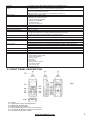
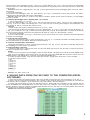
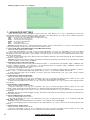
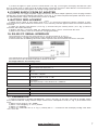
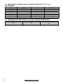
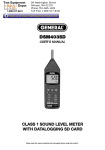
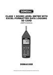
SOUND LEVEL METER
AТЕ-9030
User’s Manual
www.tmatlantic.com
Your purchase of this SOUND LEVEL METER with SD CARD DATA RECORDER marks a step forward for you into
the field of precision measurement. Although this METER is a complex and delicate instrument, its durable structure
will allow many years of use if proper operating techniques are developed. Please read the following instructions
carefully and always keep this manual within easy reach.
1. FEATURES
* Main functions are designed to meet IEC 61672 class 2.
* A & C weighting networks comply with standards.
* 0.5" standard microphone head.
* Time weighting (Fast & Slow) dynamic characteristic modes.
* Build External calibration VR.
* Auto range & Manual range selection.
* Available for external calibration adjustment.
* Condenser microphone for high accuracy & long-term stability.
* Memory function to store the Max. & Min. value.
* Hold and Peak Hold functions.
* Real time SD memory card Datalogger, it Built-in Clock and Calendar, real time data recorder, sampling time set
from 1 second to 3600 seconds.
* Manual datalogger is available (set the sampling time to 0 second), during execute the manual datalogger function,
it can set the different position (location) No. (position 1 to position 99).
* Innovation and easy operation, computer is not need to setup extra software, after execute datalogger, just take
away the SD card from the meter and plug in the SD card into the computer, it can download the all the measured
value with the time information (year/month/date/hour/minute/second) to the Excel directly, then user can make the
further data or graphic analysis by themselves.
* SD card capacity: 1 GB to 16 GB.
* LCD with green light backlight, easy reading.
* Can default auto power off or manual power off.
* Data hold, record max. and min. reading.
* Microcomputer circuit, high accuracy.
* Power by UM3/AA (1.5V) x 6 batteries or DC 9V adapter.
* RS-232/USB PC COMPUTER interface.
* Heavy duty & compact housing case.
2. SPECIFICATION
Circuit
Display
Measurement Range
Resolution
Function
Accuracy
(23 ± 5°C)
Frequency Weighting Network
Time weighting (Fast & Slow)
Data hold
Peak hold
Range selector
Frequency
Microphone type
Microphone size
Calibration VR
2
Custom one-chip of microprocessor LSI circuit
LCD size: 52×38mm. LCD with green backlight (ON/OFF)
30…130dB
0.1 dB
dB (A & C frequency weighting), Time weighting (Fast, Slow), Peak hold, Data hold, Record (Max.,
Min.).
Characteristics of "A" frequency weighting network meet IEC 61672 class 2.
Under 94dB input signal, the accuracy are:
31.5Hz ± 3.5dB
63Hz ± 2.5dB
125Hz ± 2.0dB
250Hz ± 1.9dB
500Hz ± 1.9dB
1kHz ± 1.4dB
2kHz ± 2.6dB
4kHz ± 3.6dB
8kHz ± 5.6dB
Remark: The above spec. are tested under the environment RF Field Strength less than 3 V/M &
frequency less than 30MHz only.
Characteristics of A & C.
A weighting:
The characteristic is simulated as «Human Ear Listing» response. Typical, if making the
environmental sound level measurement, always select to A weighting.
C weighting:
The characteristic is near the «FLAT» response. Typical, it is suitable for checking the noise of
machinery (Q.C.check) & knowing the sound pressure level of the tested equipment.
Fast – t= 200ms
* «Fast» range is simulated the human ear (Fast & Slow) response time weighting.
Slow – t = 500ms
* «Slow» range is easy to get the average values of vibration sound level.
To freeze the measurement value.
To keep the peak (max.) measurement value
Auto range: 30 to 130dB.
Manual range: 3 range, 30 to 80dB, 50 to 100dB, 80 to 130dB, 50dB on each step, with over &
under range indicating.
31.5 to 8,000Hz.
Electric condenser microphone.
Out size, 12.7mm DIA. (1/2 inch).
Build in external calibration VR, easy to calibrate on 94dB level by screw driver.
* Calibrated via external SOUND CALIBRATOR (SC-941, optional).
www.tmatlantic.com
Calibrator
Datalogger Sampling Time Setting
range
Memory Card
Advanced setting
Over Indication
Data Hold
Memory Recall
Sampling Time of Display
Data Output
Power off
Operating Temperature
Operating Humidity
Power Supply
Power Current
Weight
Dimension
Accessories Included
Optional Accessories
B & K (Bruel & kjaer), MULTIFUNCTION ACOUSTIC CALIBRATOR 4226.
Auto: 1 second to 3600 seconds
@ Sampling time can set to 1 second, but memory data may loss.
Manual: Push the data logger button once will save data one time.
@ Set the sampling time to 0 second.
@ Manual mode, can also select the 1 to 99 position (Location) no.
SD memory card. 1 GB to 16 GB.
* Set clock time (Year/Month/Date, setting Hour/Minute/Second)
* Decimal point of SD card setting
* Auto power OFF management
* Set beep Sound ON/OFF
* Set sampling time
* SD memory card Format
Show « - - - - ".
Freeze the display reading
Maximum & Minimum value
Approx. 1 second.
RS-232/USB PC computer interface.
* Connect the optional RS-232 cable UPCB-02 will get the RS-232 plug.
* Connect the optional USB cable USB-01 will get the USB plug.
Auto shut off saves battery life or manual off by push button.
0 to 50 °С.
Less than 85% R.H.
* Alkaline or heavy duty DC 1.5V battery (UM3, AA) x 6 PCs, or equivalent.
* DC 9V adapter input. ( AC/DC power adapter is optional ).
Normal operation (w/o SD card save data and LCD Backlight is OFF) : Approx. DC 12mA.
When SD card save the data but and LCD Backlight is OFF: Approx. DC 51mA.
* If LCD backlight on, the power consumption will increase approx. 30mA.
489g/1.08lb.
245×68×45mm. ( 9.6×2.7×1.9in).
Instruction manual........................1 PC
* Sound calibrator (94 dB).
* Sound calibrator (94/114 dB).
* Sound wind shield ball,
* SD Card (2 GB)
* USB cable.
* RS232 cable.
* Data Acquisition software.
* AC to DC 9V adapter.
* Soft carrying case.
* Hard carrying case.
3. FRONT PANEL DESCRIPTION
Fig. 1
3-1
3-2
3-3
3-4
3-5
3-6
3-7
Display.
Power Button (ESC, Backlight Button)
Hold Button (Next Button)
REC Button (Enter Button)
Range Button (▲ Button, Time Check Button)
A/C Button (▼ Button, Sampling check Button)
Fast/Slow Button (SET Button)
www.tmatlantic.com
3
3-8 Peak Hold Button (Logger Button)
3-9 Microphone
3-10 AC output terminal
3-11 Calibration VR
3-12 RS-232 output terminal
3-13 DC 9V adapter socket
3-14 Tripod Fix Nut
3-15 Battery Cover Screws
3-16 Stand
3-17 Battery compartment/Cover
3-18 SD card socket
4. MEASURING PROCEDURE
4-1 Sound level meter
1) Power on by pressing the "Power On/Off Button" (3-2, Fig. 1), the meter’s default function is "Auto range", "A
frequency weighting" & "Fast time weighting". The LCD display will show the unit "A. Fast Auto".
2) Select «A» or «C» frequency weighting by pressing the «A/C Button» (3-6, Fig. 1).
Note:
a. The characteristic table of A, C weighting.
b. The characteristic of A weighting is simulated as the «Human Ear Listening» response. Typically always select
the A weighting when makes environmental sound level measurement.
c. The C weighting characteristic is near the «FLAT» response. Typically it is suitable for checking the noise of
machinery (Q.C. check) & knowing the real sound level of the tested equipment.
3) Determine proper measuring range by pressing the «Range Button» (3-5, Fig. 1). After power on the default
range is «Auto range». In the same time the lower right display will show the text of «Auto». Under the auto range,
press the «Range Button» (3-5, Fig. 1) once step by step will enter to the manual range (range 1, range 2, range 3)
and auto range in sequence. There are still 3 manual ranges for your choice:
* Manual range 1, 30…80dB range: Display will show the unit of "30 – 80".
* Manual range 2, 50…100dB range: Display will show the unit of "50 – 100".
* Manual range 3, 80…130dB range: Display will show the unit of "80 – 130".
4) According to various measuring sound source, select the Time Weighting (Fast or Slow) by pressing the «Time
Weighting Button» (3-7, Fig. 1).
Note:
a. If select the function of «Fast» time weighting, the display will show the unit of «FAST».
b. If select the function of «Slow» time weighting, the display will show the unit of «SLOW».
4-2 Data Hold
During the measurement, press the «Hold Button» (3-3, Fig. 1) once will hold the measured value & the LCD will
display a «HOLD» symbol. Press the «Hold Button» once again will release the data hold function.
4-3 Data Record (Max., Min. reading)
1) The data record function records the maximum and minimum readings. Press the «REC Button» (3-4, Fig. 1)
once to start the Data Record function and there will be a «REC» symbol on the display.
2) With the «REC» symbol on the display:
a) Press the «REC Button» (3-4, Fig. 1) once, the «REC MAX» symbol along with the maximum value will appear
on the display. If intend to delete the maximum value, just press the «Hold Button» (3-3, Fig. 1) once, the display will
show the «REC» symbol only & execute the memory function continuously.
b) Press the «REC Button» (3-4, Fig. 1) again, the «REC MIN» symbol along with the minimum value will appear
on the display. If intend to delete the minimum value, just press the «Hold Button» (3-3, Fig. 1) once, the display will
show the «REC» symbol only & execute the memory function continuously.
c) To exit the memory record function, just press the «REC» button > 2 seconds at least. The display will revert to
the current reading.
4-4 LCD Backlight ON/OFF
After power ON, the «LCD Backlight» will light automatically. During the measurement, press the «Backlight Button»
(3-2, Fig. 1) once will turn OFF the «LCD Backlight». Press the «Backlight Button» once again will turn ON the «LCD
Backlight» again.
5. DATALOGGER
5-1 Preparation before execute datalogger function
a. Insert the SD card
Prepare a «SD memory card» (1 GB to 16 GB, optional), insert the SD card into the «SD card socket» (3-18, Fig.
1). The front panel of the SD card should face against the the down case.
b. SD card Format
If SD card just the first time use into the meter, it recommend to make the «SD card Format» at first.
c. Time setting
If the meter is used at first time, it should to adjust the clock time exactly.
d. Decimal format setting
The numerical data structure of SD card is default used the «.» as the decimal, for example «20.6» «1000.53». But
in certain countries (Europe ...) is used the «,» as the decimal point, for example «20, 6» «1000,53». Under such
situation, it should change the Decimal character at first, details of setting the Decimal point.
5-2 Auto Datalogger (Set sampling time ≥ 1 second)
a. Start the datalogger
Press the «REC Button (3-4, Fig. 1) once, the LCD will show the text «REC», then press the «Logger Button» (3-8,
Fig. 1), the «REC» will flashing sound, at the same time the measuring data along the time information will be saved
into the memory circuit.
The Display will show also show text «LOGGER» when the data save into the memory circuit.
b. Pause the datalogger
4
www.tmatlantic.com
During execute the Datalogger function, if press the «Logger Button» (3-8, Fig. 1) once will pause the Datalogger
function (stop to save the measuring data into the memory circuit temporally). In the same time the text of «REC» will
stop flashing.
Remark: If press the «Logger Button» (3-8, Fig. 1) once again will execute the Datalogger again, the text of «REC»
will flashing.
c. Finish the Datalogger
During pause the Datalogger, press the «REC Button» (3-4, Fig. 1) continuously at least two seconds, the «REC»
indicator will be disappeared and finish the Datalogger.
Remark: When the battery is under the low battery condition (show the low battery indicator), the Datalogger
function is disable.
5-3 Manual Datalogger (Set sampling time = 0 second)
a. Set sampling time is to 0 second
Press the «REC Button» (3-4, Fig. 1) once, the LCD will show the text «REC», then press the «Logger Button»
(3-8, Fig. 1) once, the «REC» will flashing once, at the same time the measuring data along the time information and
the Position no. will be saved into the memory circuit.
Remark:
* Lower Display will show the Position/Location no. (P1, P2... P99).
* During execute the Manual Datalogger, press the «SET Button» (3-7, Fig. 1 ) once, then use the «▲ Button» (35, Fig. 1) or «▼ Button» (3-6, Fig. 1) to set the measuring position (1 to 99, for example room 1 to room 99) to identify
the measurement location. After finish the adjustment location no., press the «Enter Button» to entry.
b. Finish the Datalogger
Press the «REC Button» (3-4, Fig. 1) continuously at least two seconds, the «REC» indication will be disappeared
and finish the Datalogger.
5-4 Check time information
During the measurement if press «Time check Button» (3-5, Fig. 1) > 2 seconds, the lower LCD display will present
the time information of Year/Month, Date/Hour, Minute/Second.
5-5 Check sampling time information
During the measurement, If press «Sampling Check Button» (3-6, Fig. 1) once , the lower LCD display will present
the Sampling time information in second unit.
5-6 SD Card Data structure
1) When the SD card is used into the meter, the SD card When the first time, the SD card is used into the meter,
the SD card will generate a folder :
SLA01
2) If the first time to execute the Datalogger, under the route SLA01\, will generate a new file name SLA01001.XLS.
After exist the Datalogger, then execute again, the data will save to the SLA01001.XLS until Data column reach to
30,000 columns, then will generate a new file, for example SLA01002.XLS
3) Under the folder SLA01\, if the total files more than 99 files, will generate anew route, such as SLA02\ ........
4) The file’s route structure:
SLA01\
SLA01001.XLS
SLA01002.XLS
.....................
SLA01099.XLS
SLA02\
SLA02001.XLS
SLA02002.XLS
.....................
SLA02099.XLS
SLAXX\
.....................
.....................
Remark: XX : Max. value is 10.
6. SAVING DATA FROM THE SD CARD TO THE COMPUTER (EXCEL
SOFTWARE)
1) After execute the Data Logger function, take away the SD card out from the «SD card socket» (3-18, Fig. 1).
2) Plug in the SD card into the Computer’s SD card slot (if your computer build in this installation) or insert the SD
card into the «SD card adapte». Then connect the «SD card adapter» into the computer.
3) Power ON the computer and run the «EXCEL software». Down load the saving data file (for example the file
name: SLA01001.XLS, SLA01002.XLS) from the SD card to the computer. The saving data will present into the
EXCEL software screen (for example as following EXCEL data screens), then user can use those EXCEL data to make
the further Data or Graphic analysis usefully.
EXCEL data screen (for example)
www.tmatlantic.com
5
EXCEL graphic screen ( for example )
7. ADVANCED SETTING
Under do not execute the Datalogger function, press the «SET Button» (3-7, Fig. 1) continuously at least two
seconds will enter the «Advanced Setting» mode. Then press the «Next Button» (3-3, Fig. 1) once a while in sequence
to select the six main function, the lower display will show:
dAtE......Set clock time ( Year/Month/Date, Hour/Minute/Second)
dEC.......Set SD card Decimal character
PoFF..... Auto power OFF management
bEEP.....Set beeper sound ON/OFF
SP-t...... Set sampling time
Sd-F..... SD memory card Format
Remark: During execute the « Advanced Setting "function, if press «ESC Button» ( 3-2, Fig. 1) once will exit the
«Advanced Setting» function, the LCD will return to normal screen.
7-1 Set clock time (Year/Month/Date, Hour/Minute/Second)
When the lower display show «dAtE»
1) Press the «Enter Button» (3-4, Fig. 1) once, Use the «▲ Button» (3-5, Fig. 1) or «▼ Button» (3-6, Fig. 1) to adjust
the value ( Setting start from Year value ). After the desired value is set, press the «Enter Button» (3-4, Fig. 1) once
will going to next value adjustment ( for example, first setting value is Year then next to adjust Month, Date, Hour,
Minute, Second value).
2) After set all the time value (Year, Month, Date, Hour, Minute, Second ), the screen will jump to «SD card Decimal
character» setting screen.
Remark: After the time value is setting, the internal clock will run precisely even Power is off (The battery is under
normal condition, no low battery condition).
7-2 Decimal point of SD card setting
The numerical data structure of SD card is default used the «.» as the decimal, for example «20.6» «1000.53». But
in certain countries (Europe ...) is used the «,» as the decimal point, for example «20,6» «1000,53». Under such
situation, it should change the Decimal character at first.
When the lower display show «dEC»
1) Use the «▲ Button» (3-5, Fig. 1) or «▲ Button» (3-6, Fig. 1) to select the upper value to «bASIC» or «Euro».
bASIC – Use «.» as the Decimal point with default. Euro – Use «,» as the Decimal point with default.
2) After select the upper text to «bASIC» or «Euro», press the «Enter Button» (3-4, Fig. 1) will save the setting
function with default.
7-3 Auto power OFF management
When the lower display show «PoFF»
1) Use the «▲ Button» (3-5, Fig. 1) or «▼ Button» (3-6, Fig. 1) to select the upper value to «yES» or «no». yES
–Auto Power Off management will enable. no – Auto Power Off management will disable.
2) After select the upper text to «yES» or «no», press the «Enter Button» (3-4, Fig. 1) will save the setting function
with default.
7-4 Set beeper sound ON/OFF
When the lower display show «bEEP»
1) Use the «▲ Button» (3-5, Fig. 1) or «▼ Button» (3-6, Fig. 1) to select the upper value to «yES» or «no». yES
– Meter’s beep sound will be ON with default. no – Meter’s beep sound will be OFF with default.
2) After select the upper text to «yES» or «no», press the «Enter Button» (3-4, Fig. 1) will save the setting function
with default.
Remark: After execute the datalogger function, the buzzer sound will off automatically to prevent any interference
of the measurement.
7-5 Set sampling time (seconds)
When the lower display show «SP-t»
1) Use the «▲ Button» (3-5, Fig. 1) or «▼ Button» (3-6, Fig. 1) to adjust the value (0, 1, 2, 5, 10, 30, 60, 120, 300,
600, 1800, 3600 seconds).
Remark: If select the sampling time to «0 second», it is ready for manual Datalogger.
2) After the Sampling value is selected, press the «Enter Button» (3-4, Fig. 1) will save the setting function with
default.
7-6 SD memory card Format
When the lower display show «Sd F»
1) Use the «▲ Button» (3-5, Fig. 1) or «▼ Button» (3-6, Fig. 1) to select the upper value to «yES» or «no». yES
– Intend to format the SD memory card, no – Not execute the SD memory card format.
6
www.tmatlantic.com
2) If select the upper to «yES», press the «Enter Button» (3-4, Fig. 1) once again, the Display will show text «yES
Ent» to confirm again, if make sure to do the SD memory card format, then press «Enter Button» once will format the
SD memory clear all the existing data that already saving into the SD card.
8. POWER SUPPLY FROM DC ADAPTER
The meter also can supply the power supply from the DC 9V Power Adapter (optional). Insert the plug of Power
Adapter into «DC 9V Power Adapter Input Socket» (3-13, Fig. 1). The meter will permanent power ON when use the
DC ADAPTER power supply (The power Button function is disable).
9. BATTERY REPLACEMENT
1) When the left corner of LCD display show «
», it is necessary to replace the battery. However, in-spec.
measurement may still be made for several hours after low battery indicator appears before the instrument become
inaccurate.
2) Loose the «Battery Cover Screws» (3-15, Fig. 1) and take away the «Battery Cover» (3-17, Fig. 1) from the
instrument and remove the battery.
3) Replace with DC 1.5 V battery (UM3, AA, Alkaline/heavy duty) x 6 PCs, and reinstate the cover.
4) Make sure the battery cover is secured after changing the battery.
10. RS-232 PC SERIAL INTERFACE
The instrument has RS-232 PC serial interface via a 3.5mm terminal (3-12, Fig. 1).
The data output is a 16 digit stream which can be utilized for user’s specific application.
A RS-232 lead with the following connection will be required to link the instrument with the PC serial port.
The 16 digits data stream will be displayed in the following format:
D15 D14 D13 D12 D11 D10 D9 D8 D7 D6 D5 D4 D3 D2 D1 D0
Each digit indicates the following status:
D15
Start Word
D14
4
D13
When send the upper display data = 1
When send the lower display data = 2
D12, D11
Annunciator for Display
dB = 17
D10
Polarity
0 = Positive 1 = Negative
D9
Decimal Point (DP), position from right to the left
0 = No DP, 1= 1 DP, 2 = 2 DP, 3 = 3 DP
D8 to D1
Display reading, D1 = LSD, D8 = MSD
For example:
If the display reading is 1234, then D8 to D1 is : 00001234
D0
End Word
RS232 FORMAT: 9600, N, 8, 1
Baud rate
9600
Parity
No parity
Data bit no.
8 Data bits
Stop bit
1 Stop bit
11. CALIBRATION
1) Prepare the optional «SOUND CALIBRATOR», such as «SC-941» or «SC-942» (set range to 94.0 dB). Power
on the Sound Calibrator & plug calibrator output socket into the «Microphone» head (3-1, Fig. 1) of the Sound Level
meter.
2) Select manual range to «50…100dB».
3) Select «Time Weighting» at «Fast» position.
4) Select «A» weighting.
5) Adjust the «Calibration VR» (3-11, Fig. 1) carefully with a «-» screw driver until the display reading value within
«94 +/- 0.2» dB.
www.tmatlantic.com
7
12. FREQUENCY WEIGHTING CHARACTERISTICS OF A & C
NETWORKS
Frequency, Hz
31.5
63
125
250
500
1k
2k
4k
8k
A Weighting Charac., dB
-39.4
-26.2
-16.1
-8.6
-3.2
0
+1.2
+1
-1.1
C Weighting Charac., dB
-3
-0.8
-0.2
0
0
0
-0.2
-0.8
-3
Tolerance (IEC 61672 class 2), dB
± 3.5
± 2.5
± 2.0
± 1.9
± 1.9
± 1.4
± 2.6
± 3.6
± 3.6
13. TIME WEIGHTING (FAST & SLOW) CHARACTERISTICS
8
Time Weighting Charac.
Max. response ref. continuous signal
F (Fast)
-1.0dB
S (Slow)
-4.1dB
www.tmatlantic.com
Tolerance (IEC 61672 class 2)
+1dB
-2dB
± 2dB