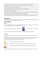
1
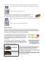
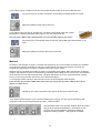
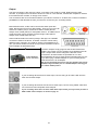
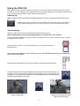
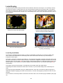
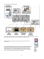
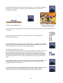
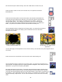
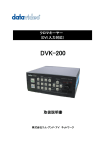
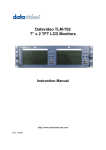
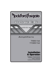
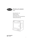
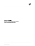
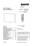
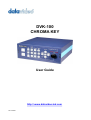
DVK-100 CHROMA KEY User Guide http:// www.datavideo-tek.com Rev: 020306 Contents Warnings and Precautions ----------------------------------------------------------------------------------4 Warranty -----------------------------------------------------------------------------------------------------------5 What is in the package ----------------------------------------------------------------------------------------5 Introduction -------------------------------------------------------------------------------------------------------6 Backdrops --------------------------------------------------------------------------------------------------6 Lighting ------------------------------------------------------------------------------------------------------6 White Balance ---------------------------------------------------------------------------------------------7 Functions ----------------------------------------------------------------------------------------------------------8 Front Panel ------------------------------------------------------------------------------------------------8 Rear Panel ----------------------------------------------------------------------------------------------- 10 Installation ------------------------------------------------------------------------------------------------------- 12 Setting Up ------------------------------------------------------------------------------------------------------- 13 Connections----------------------------------------------------------------------------------------------------- 13 Power ---------------------------------------------------------------------------------------------------- 13 Cameras ------------------------------------------------------------------------------------------------ 13 Background Video ------------------------------------------------------------------------------------ 14 Monitors ------------------------------------------------------------------------------------------------- 15 Output --------------------------------------------------------------------------------------------------- 16 Using the DVK-100 -------------------------------------------------------------------------------------------- 17 Powering Up------------------------------------------------------------------------------------------------ 17 Chroma Keying------------------------------------------------------------------------------------------- 17 Edge Adjustment (Shrink)--------------------------------------------------------------------------- 18 Subject Density---------------------------------------------------------------------------------------- 19 Spill Adjustment --------------------------------------------------------------------------------------- 19 Window Adjustment ---------------------------------------------------------------------------------- 20 Settings Lock ------------------------------------------------------------------------------------------ 21 Reset ---------------------------------------------------------------------------------------------------- 21 Luma Keying ---------------------------------------------------------------------------------------------- 22 Luma Key Installation -------------------------------------------------------------------------------- 22 Luma Key Settings ----------------------------------------------------------------------------------- 23 Colour Processor---------------------------------------------------------------------------------------- 26 Still Freeze Frame ------------------------------------------------------------------------------------- 26 GPI Control ------------------------------------------------------------------------------------------------------ 27 2 RS 232 Information ------------------------------------------------------------------------------------------------ 28 Specifications ------------------------------------------------------------------------------------------------------- 29 Optional Accessories ---------------------------------------------------------------------------------------------- 30 Service and Support ---------------------------------------------------------------------------------------------- 31 3 Warnings and Precautions 1. Read all of these warnings and save them for later reference. 2. Follow all warnings and instructions marked on this unit. 3. Unplug this unit from the wall outlet before cleaning. Do not use liquid or aerosol cleaners. Use a damp cloth for cleaning. 4. Do not use this unit in or near water. 5. Do not place this unit on an unstable cart, stand, or table. The unit may fall, causing serious damage. 6. Slots and openings on the cabinet top, back, and bottom are provided for ventilation. To ensure safe and reliable operation of this unit, and to protect it from overheating, do not block or cover these openings. Do not place this unit on a bed, sofa, rug, or similar surface, as the ventilation openings on the bottom of the cabinet will be blocked. This unit should never be placed near or over a heat register or radiator. This unit should not be placed in a built-in installation unless proper ventilation is provided. 7. This product should only be operated from the type of power source indicated on the marking label of the AC adapter. If you are not sure of the type of power available, consult your Datavideo dealer or your local power company. 8. Do not allow anything to rest on the power cord. Do not locate this unit where the power cord will be walked on, rolled over, or otherwise stressed. 9. If an extension cord must be used with this unit, make sure that the total of the ampere ratings on the products plugged into the extension cord do not exceed the extension cords rating. 10. Make sure that the total amperes of all the units that are plugged into a single wall outlet do not exceed 15 amperes. 11. Never push objects of any kind into this unit through the cabinet ventilation slots, as they may touch dangerous voltage points or short out parts that could result in risk of fire or electric shock. Never spill liquid of any kind onto or into this unit. 12. Except as specifically explained elsewhere in this manual, do not attempt to service this product yourself. Opening or removing covers that are marked Do Not Remove may expose you to dangerous voltage points or other risks, and will void your warranty. Refer all service issues to qualified service personnel. 13. Unplug this product from the wall outlet and refer to qualified service personnel under the following conditions: a. When the power cord is damaged or frayed; b. When liquid has spilled into the unit; c. When the product has been exposed to rain or water; d. When the product does not operate normally under normal operating conditions. Adjust only those controls that are covered by the operating instructions in this manual; improper adjustment of other controls may result in damage to the unit and may often require extensive work by a qualified technician to restore the unit to normal operation; e. When the product has been dropped or the cabinet has been damaged; f. When the product exhibits a distinct change in performance, indicating a need for service. 4 Warranty Datavideo warrants that the equipment it manufactures shall be free from defects in material and workmanship for a period of 12 months from the date of product purchased. If equipment fails due to such defects, Datavideo will, at its option, repair or provide a replacement for the defective part or product. Equipment that fails after the warranty period, has been operated or installed in a manner other than that specified by Datavideo, or has been subjected to abuse or modification, will be repaired for time and material charges at the Buyers expense. This warranty does not affect your statutory rights within the Country of purchase. For EU Customers only - WEEE Marking. This symbol on the product indicates that it will not be treated as household waste. It must be handed over to the applicable take-back scheme for the recycling of electrical and electronic equipment. For more detailed information about the recycling of this product, please contact your local Datavideo office. What is in the Package 1 x DVK 100 Chroma Key Unit 1 x User Guide (this document) 1 x Power Supply (12V 3.0A) 1 x Power Cord 2 x S-Video (Y/C) Plug to Plug Cable 1.2m 1 x BNC Plug to Plug Cable 1.2m 5 Introduction The Datavideo DVK-100 is a two camera live chroma keyer. It has many advanced features which can give excellent results even from less than perfect Chroma Key setups. Although the DVK-100 is equipped with excellent edge controls it is always best to start with the best keyable image your setup is able to produce. Please read these advisory notes before using the DVK-100 as the camera, backdrop and lighting setups all play an important role in producing the best result. We would strongly recommend the use of a three chip (3 CCD) camera for chroma effect shooting. The extra image clarity that a three chip camera produces greatly improves the quality of the keying. It is also best to use S-Video (Y/C) cables wherever possible. An S-Video signal offers better colour separation than a Composite video signal, and again this greatly improves the quality of the keying. Backdrops There are many different possibilities when it comes to setting up a Chroma Key Studio. In a permanent set up the use of Green Screen or Blue Screen Paint is ideal. Painting a wall is the cheapest way of producing a Green or Blue backdrop and there are several suppliers of specialist backdrop paint which is exactly the right shade and texture for keying purposes. For a less permanent arrangement cloth is an excellent option. Again there are specialist manufacturers producing Green and Blue Screen cloth which is the right shade and texture to give excellent keying results. Cloth is quick to setup, and roll away, and is far more durable than paper. Cloth is also less likely to fade than paper, and generally gives far better performance. It is important to ensure there are no creases or folds in the backdrop as these may produce areas of uneven lighting. Another alternative well worth considering is the range of backdrops from Reflecmedia www.relecmedia.com. Reflecmedia produce unique backdrops which are embedded with tiny glass beads. These backdrops are used in conjunction with LED LiteRings that mount on the lens of the camera. The unique properties of the backdrop will allow you to get away with having the odd crease line, and the whole system is extremely quick to set up. If you are looking for a portable system you will be hard pushed to beat the Reflecmedia systems. Lighting Lighting of your chosen backdrop is extremely important; the more even the lighting on the backdrop the better the finished result. Lighting setups for the foreground will vary according to the effect youre after, but as far as chroma keying backdrops are concerned even lighting with no hotspots or shadow areas is the aim. This is easiest to achieve with a set up something like this: In the diagram you will see we recommend a minimum of 1m between subject and backdrop, it is always easier to get even lighting if this distance is greater, so please think of 1m as the absolute minimum. The foreground lighting on the subject will obviously vary according to the effect that you are looking for and as long as the backdrop is evenly lit this should not be a problem. 6 Lighting for Reflecmedia is a little different. The backdrop requires no lighting as the LiteRing, which is mounted on the camera provides all the lighting for the backdrop. A Reflecmedia setup would be more like this: More in-depth details of Reflecmedia lighting setups are available from the Reflecmedia website: www.reflecmedia .com White Balance White Balance is extremely important when setting up a chroma key studio. The camera must be correctly white balanced to prevent the subject picking up any colour cast from the background. Of course the white balance settings will vary according to the type of lighting you are using, but neutral whites are the all important target. To set the white balance you will need a white reference card (or a sheet of white paper). Focus the camera on the reference card and light it evenly using the main light. Set the cameras iris / aperture so that the card is correctly exposed. Use the Auto White Balance function, or set the white balance manually so that the card appears white. If in any doubt about how to white balance your camera, please refer to your camera instruction manual for details. 7 Functions The DVK-100 has three inputs (two camera inputs and one background input). Each of the inputs can be set to Y/C (S-Video) or Composite. All the outputs, one Y/C (S-Video) and two Composite, are simultaneously live. We recommend that Y/C is used for the camera inputs wherever possible. Front Panel CAM-1 and CAM-2 are used to select the input that you want to use or setup. The active input will be illuminated in red. Each camera input has individual settings. The settings are non-volatile (they remain stored even when the DVK-100 is switched off). The settings for both cameras can be locked by pressing and holding either camera button for two seconds. When locked the active camera button will turn amber instead of red The Adjustment Knob is used to alter whichever function is active. The unity position, indicated in green is the neutral setting. The adjustment scale is marked in nominal settings from -3 to +3. The adjustment can also be used to reset any value to factory default; activate the function you want to reset by pressing the appropriate function button, and then push the adjustment knob in, you will see the LED meter return to unity. The Arrow Buttons adjust the window size and the left and right edge. The spill button adjusts the colour balance of the keyed image; it enables you to correct any colour imbalance that remains on the foreground image once the backdrop has been keyed out. The window size can be set to remove any unwanted garbage from the foreground image. Often your backdrop does not fill the whole screen, particularly if you want your subject to appear small in the finished image. You can use the Up / Down / Left / Right arrows to make the keying window smaller so that only your backdrop is being keyed. To adjust left or right edge press and hold the Left or Right Arrow for two seconds, the button will flash. While the button is flashing you can adjust the edge detail of the subject, you will see the value on the LED meter above the adjustment knob. The Color Processor button activates the colour processor adjustments (see below) for Foreground (Cam-1 or Cam-2) or Backgroundò The button will be illuminated red when foreground is selected. 8 The Color Processor Adjustments allow colour saturation, brightness, contrast and tint (NTSC only) to be adjusted for both the foreground (Cam-1 / Cam-2) and background images. The selected parameter, which will be illuminated red, is adjusted using the Adjustment Knob. Cam-1 and Cam-2 store separate values, so different colour processor settings can be used on each. The Still button enables you to grab a freeze frame image from either the background or foreground inputs. This can be useful when setting up. N.B. The colour processor adjustments will not function if you are holding a freeze frame. The Reset button resets a foreground channel (Cam-1 or Cam-2) to factory default. This will reset all characteristics of a channel (COLOR PROC. /GREEN / BLUE / LUMA / LEVEL / WINDOW / SHRINK / DENSITY / SPILL) The Chroma Key button switches the keying effect on or off. In the off position the foreground channel (Cam-1 or Cam-2) will pass directly to the output monitor, complete with backdrop. When switched on the button will be illuminated red together with the chosen keying option (Green, Blue or Luma) see below. Green, Blue and Luma are the three keying options available. With the Chroma Key button switched on, you can select the keying option to suit your needs. The selected option will be illuminated red. When the button is illuminated red you can adjust the keying colour, to fine tune it for your studio; you can see the setting on the LED meter above the adjustment knob(although what appears on your monitor is more important). If another adjustment has been selected, such as density or spill, the keying option light will be illuminated 50% to indicate which option you have selected. Level or Density adjusts the range of the keyer. The button will be illuminated red when active. The value is adjusted using the adjustment knob, you will see the level on the LED meter above the knob (although what appears on your monitor is more important). If the background is perfectly lit a low value will be adequate, if there are variances in the background a higher value will allow you to remove them. The subject density can also be adjusted. If you press and hold the button for two seconds the button will flash, while the button is flashing you can adjust subject density. In Green or Blue modes a low value makes the subject solid, the edges will be sharper and any shadow noise will be higher, a higher value makes the subject more transparent, the edges will be softer and the shadow noise lower. In Luma mode the subject density will adjust the white gradient of the subject 9 Rear Panel The Input Select Switches can be set to CV (Composite Video) or S (S-Video (Y/C)). Always use S-Video if available. Set each input according to the video signal you are connecting. CAM-1 and CAM-2 Video Inputs for connecting the two foreground video images. There are Composite and S-Video Inputs, at the top and Composite and S-Video Loop Through outputs below. The S-Video input can be monitored from the Composite Video Loop Through if required. ̸» ÍóÊ·¼»± Ô±±° ̸®±«¹¸ ·- ±²´§ ¿½¬·ª» ·º ¬¸» ÍóÊ·¼»± ·²°«¬ ·- «-»¼ò ÒòÞò Ú±® ¾»-¬ ®»-«´¬- ¿´©¿§- «-» ¿² ÍóÊ·¼»± -·¹²¿´ ·º ¿ª¿·´¿¾´»ò Background Input (BG Input) for connecting the video feed from your background source. This could be from a VTR or DVD player for example. The Composite and S-Video Inputs are at the top, and the Loop Through Outputs are below. The S-Video input can be monitored from the Composite Video Loop Through if required. ̸» ÍóÊ·¼»± Ô±±° ̸®±«¹¸ ·- ±²´§ ¿½¬·ª» ·º ¬¸» ÍóÊ·¼»± ·²°«¬ ·- «-»¼ò The Main Video Output shows the final result of the keyer. There are two composite outputs and one S-Video (Y/C), all three are active simultaneously. It is advisable to connect a monitor to one of the outputs so that you can see exactly what the DVK-100 is outputting. Power Switch, switches the DVK-100 on/off. DC In. Connect the power supply to the DC In, there is a locking collar on the power supply lead which screws onto the socket to ensure a positive connection. It is also possible to power the DVK-100 from a suitable 12V Battery Pack, but please ensure that the power is regulated. Grounding Terminal. When connecting this unit to any other component, make sure that it is properly grounded by connecting this terminal to an appropriate point. When connecting, use the socket and be sure to use wire with a cross-sectional area of at least 1.0 mm2. 10 Dip Switches / Mode Select The DVK-100 can be set to various modes using the Dip Switches. Dip Switch 1 : OFF = NTSC, ON = PAL output 2 : OFF = 0 IRE, ON = 7.5IRE input/output 3 : OFF = Fixed, ON = PAL/NTSC auto detection (Detected from the CAM-1 / CAM-2 signal) 4, 5 : RESERVED 6 : OFF = VIDEO, ON = COLOR BAR Cooling Fan. Please ensure that there is free air flow available around the fan. Blocking the fan may cause the unit to overheat. The DVK-100 can be fully controlled via RS232 please refer to the RS 232 protocols on page 28 for further details. The DVK-100 can be partially controlled via GPI trigger. Using the GPI In socket you can switch from Cam-1 to Cam-2 remotely (via a 3.5mm cable with latching switch) The GPI Out Socket 11 Installation Here is an example chroma key installation diagram (for an example luma key installation see page 21): The Studio Set-Up for this example would be something like this: 12 In this example both Camera 1 and Camera 2 are connected using S-Video (Y/C) cables, as this gives the best results. Camera 1 is set as a close-up of the anchorman and Camera 2 is a wider shot. The Background footage is being fed from a DVD Player, and again it is connected using S-Video. You could alternatively use a VCR or even another camera. The Output is being recorded to a DVD Recorder via an S-Video cable. You could alternatively record to a VCR or a Hard Drive Recorder, or send the output to a PC for a live webcast. The Output Monitor is taking a Composite Video Output from the DVK-100; optionally it could be taking a feed from the DVD Recorder output. Three monitors are connected to the Camera 1, Camera 2 and Background Loop-Through Outputs, these are optional, but are very handy when setting up. A bank of small monitors such as the Datavideo TLM-404 may be sufficient for this purpose (see optional accessories on page 30) There are no audio connections in the diagram, as the DVK-100 only needs to process the video signal. The audio would typically be fed via an audio mixer directly to the audio inputs of the DVD Recorder / VCR. Setting Up The DVK-100 is quite easy to set up, and over the next few pages we will look at all aspects configuring the DVK-100 for your studio. We will start with connections. Connections Power The DVK-100 is supplied with a 12V 3.0A Power Supply, and a power cord to connect it to a mains supply. The Power Supply has a 2.1mm in-line plug with a locking collar. Push the plug into the DC In Socket of the DVK-100, and screw the locking collar into place. Connect the power cord to the power supply and then to an appropriate mains power outlet. Cameras The two Camera Inputs are the same, so we will look at Camera 1 only (Camera 2 will follow the same principal). It is best wherever possible to use an S-Video (Y/C) cable for connecting the camera. Good results can be achieved using Composite Video, but S-Video connections will always give optimum results. Most cameras have video outputs that look something like this: S-Video (Y/C) Output via 4 Pin Mini Din Plug Composite Video Output via RCA / Phono Plug (Generally colour coded yellow) Left and Right Audio Out (Generally colour coded white for left, and red for right) The DVK-100 only requires video connection, so we do not need to worry about the audio connections. 13 If your camera has an S-Video Out connect it to the CAM-1 S-Video Input on the rear of the DVK-100 As you are using an S-Video connection, set the CAM-1 Input Select Switch to S Input Camera 1 (CAM-1) S-Video Input Connector If your camera does not have an S-Video Out, connect the Composite Video Out (Yellow RCA/Phono) to the CAM-1 Composite Video Input on the rear of the DVK-100. øDZ« ³¿§ ²»»¼ ¿ ÞÒÝ ¬± ÎÝß ñ и±²± ß¼¿°¬±® ¬± ½±²²»½¬ ¬¸» ÞÒÝ ½¿¾´» ¬± §±«® ½¿³»®¿÷ As you are using a Composite Video connection, set the CAM-1 Input Select Switch to CV Input. Camera 1 (CAM-1) Composite Video Input Connector Background Video Next we will connect the background video source. The background video is the footage that you want behind your subject in the finished video. A few examples of backgrounds would be a virtual studio, or a weather map or perhaps a famous building or landmark. You can feed any video signal as the background source; most often the footage will be coming from a VCR or DVD Player. DVD Players and VCRs generally have one of two types of video output: Most DVD Players and VCRs have outputs like these, although the layout may differ slightly. There is a mini 4 pin din socket for S-Video (Y/C) out, and a RCA / Phono socket (almost always colour coded yellow) for Composite Video Out. In addition there will be two RCA / Phono sockets for left and right audio (almost always colour coded white and red). Some DVD Players and VCRs (mostly in Europe) use a SCART connector instead of the above. A SCART connector carries many different types of signal in one multi pin socket. The easiest thing to do if you have a SCART connector is to purchase a SCART to RCA / Phono Adaptor as illustrated below. SCART ADAPTOR with In / Out Switch A SCART Adaptor simply plugs into the SCART Socket and breaks it out to RCA / Phono Sockets. Some adaptors have an Input / Output switch which changes the direction of the connections, whereas others are specified as In or Out. Some adaptors have an S-Video Socket whereas others do not. If you are buying a SCART adaptor for your playback device make sure that it is an OUT adaptor. SCART Adaptor with S-Video Socket ÒòÞò ׺ §±«® ÊÝÎ ±® ÜÊÜ Ð´¿§»® ¼±»- ²±¬ ¸¿ª» ÍóÊ·¼»± ±«¬°«¬ ª·¿ ¬¸» ÍÝßÎÌô «-·²¹ ¿² ÍóÊ·¼»± °±®¬ ±² ¿ ÍÝßÎÌ ß¼¿°¬±® ©·´´ ±²´§ ¹·ª» §±« ¿ ¾´¿½µ ú ©¸·¬» °·½¬«®»ò 14 If your player has an S-Video Out connect it to the BG S-Video Input on the rear of the DVK-100 As you are using an S-Video connection, set the BG Input Select Switch to S Input Background (BG) S-Video Input Connector If your player does not have an S-Video Out, connect the Composite Video Out (Yellow RCA/Phono) to the BG Composite Video Input on the rear of the DVK-100. øDZ« ³¿§ ²»»¼ ¿ ÞÒÝ ¬± ÎÝß ñ и±²± ß¼¿°¬±® ¬± ½±²²»½¬ ¬¸» ÞÒÝ ½¿¾´» ¬± §±«® °´¿§»®÷ As you are using a Composite Video connection, set the BG Input Select Switch to CV Input Background (BG) Composite Video Input Connector Monitors As shown in the example on page 11 the DVK-100 could have up to four monitors connected. It is possible to use just one monitor, connected to one of the output sockets, but many users prefer to monitor the Cameras and the Background Video in addition to the main monitor output. Monitors can be connected using either S-Video or Composite Video cables. Many monitors do not feature S-Video, and therefore must be connected using Composite Video cables, this is not too much of a limitation as the monitor does not affect the final result. The DVK-100 allows you to use Composite Video monitors even if you are using S-Video inputs from your cameras and player. To connect the master monitor to the DVK-100 use one of the Composite Video Outputs. ׺ §±«® ³±²·¬±® ¼±»- ²±¬ ¸¿ª» ¿ ÞÒÝ Ê·¼»± ײ°«¬ -±½µ»¬ §±« ³¿§ ²»»¼ ¬± °«®½¸¿-» ¿ ÞÒÝ ¬± ÎÝß ñ и±²± ¿¼¿°¬±®ô ¿- -¸±©² ¿¾±ª»ò Use either one of the Composite Video outputs to feed your master monitor. If you want to add monitors to your Camera and Background Inputs, you can connect monitors to the Composite Video Loop Through Outputs of CAM-1, CAM-2 and BG The Composite Video Loop Through Outputs allow each input channel to be monitored separately. A small bank of LCD monitors such as the Datavideo TLM-404 is ideal as a compact monitoring solution See page 30 for details. 15 Output The final connection is the output to a deck, or recorder. This could be a VCR, DVD Recorder, HDD recorder, or perhaps a DV Converter to stream to a PC for a live webcast, a distribution amplifier to several live monitors and a recorder, or simply a live monitor. The connections are much the same whatever you intend to connect to. As there are a number of different possibilities we will describe the item you intend to connect as your recording device Most DVD Recorder, VCRs, and DV Converters have inputs like these, although the layout may differ slightly. There is a mini 4 pin din socket for S-Video (Y/C) In, and a RCA / Phono socket (almost always colour coded yellow) for Composite Video In. In addition there will be two RCA / Phono sockets for left and right audio (almost always colour coded white and red). Some DVD Recorders and VCRs (mostly in Europe) use a SCART connector instead of the above. A SCART connector carries many different types of signal in one multi pin socket. The easiest thing to do if you have a SCART connector is to purchase a SCART to RCA / Phono Adaptor as illustrated below. A SCART Adaptor simply plugs into the SCART Socket and breaks it out to RCA / Phono Sockets. Some adaptors have an Input / Output switch which changes the direction of the connections, whereas others are specified as In or Out. SCART ADAPTOR with In / Out Switch Some adaptors have an S-Video Socket whereas others do not. If you are buying a SCART adaptor for your recording device make sure that it is an IN adaptor. ÒòÞò ׺ §±«® λ½±®¼·²¹ Ü»ª·½» ¼±»- ²±¬ ¸¿ª» ÍóÊ·¼»± ·²°«¬ ª·¿ ¬¸» ÍÝßÎÌô «-·²¹ ¿² ÍóÊ·¼»± °±®¬ ±² ¿ ÍÝßÎÌ ß¼¿°¬±® ©·´´ ±²´§ ¹·ª» §±« ¿ ¾´¿½µ ú ©¸·¬» °·½¬«®»ò If your recording device has an S-Video Input, connect using an S-Video cable from the DVK-100 S-Video Output. If your recording device does not have an S-Video Input, connect using a BNC cable from one of the DVK-100 Composite Video Outputs. ׺ §±«® ®»½±®¼·²¹ ¼»ª·½» ¼±»- ²±¬ ¸¿ª» ¿ ÞÒÝ Ê·¼»± ײ°«¬ -±½µ»¬ §±« ³¿§ ²»»¼ ¬± °«®½¸¿-» ¿ ÞÒÝ ¬± ÎÝß ñ и±²± ¿¼¿°¬±®ô ¿- -¸±©² ±² °¿¹» ïìò 16 Using the DVK-100 With all devices and monitors connected correctly we can now look at how to operate the DVK-100. Firstly we will look at Chroma Keying. In this example we are using a Green Backdrop; the principle is exactly same if you are using a Blue Backdrop, just press Blue instead of Green. Powering Up Make sure the powercord is plugged into an appropriate mains socket, and that the socket is switched on. Switch the DVK-100 on, using the On / Off switch on the rear of the unit. All the buttons on the front panel should light up for a couple of seconds, and then the DVK-100 is ready. Chroma Keying Switch on your cameras, lighting, background video player and monitor/s. Þ»º±®» -¬¿®¬·²¹ °´»¿-» »²-«®» ¬¸¿¬ ¬¸» ɸ·¬» Þ¿´¿²½» ·- ½±®®»½¬´§ -»¬ ±² §±«® ½¿³»®¿-ò The DVK-100 stores separate settings for CAM-1 and CAM-2, so we will start by setting up CAM-1, CAM-2 will follow the same routine. Press the CAM-1 button on the front of the DVK-100, once pressed it should be illuminated red. É» ¿®» «-·²¹ ¿ Ù®»»² Þ¿½µ¼®±° ·² ¬¸·- »¨¿³°´»å ·º §±« ¿®» «-·²¹ ¿ Þ´«» Þ¿½µ¼®±° °´»¿-» °®»-- ¬¸» Þ´«» ¾«¬¬±² ®¿¬¸»® ¬¸¿² ¬¸» Ù®»»² ¾«¬¬±²ò Press the Chroma Key button and the Green button, both should be illuminated red. Use the Adjustment Knob to adjust the Green Keying level. You should see the effect on the output monitor. Set the Green Keying Level to eliminate as much of the Backdrop as possible. In the example below the backdrop has been deliberately set up poorly so that the different adjustments can be seen Subject on Backdrop Subject and Backdrop after Green Keying Level Adjustment 17 Now press the Density (Level) button. The Chroma Key and Density buttons should both be illuminated red. Again use the Adjustment Knob to eliminate as much backdrop as possible. Before Density Adjustment- After Density Adjustment- Creases and areas of shadow can be seen. The Backdrop has now become completely transparent. Edge Adjustment (Shrink) Once Density has been adjusted we should be getting a pretty good Chroma Key Effect. It is often worth going back to the Green Keying Level Adjustment to fine tune after the density has been adjusted. If your backdrop and subject are well lit you may not need to fine tune the result, however there will be occasions when the subject still has a dark edge even when you have set the Green Keying and Density Levels correctly. This is why the DVK-100 has Left and Right Edge Shrink Functions. If we look closely at the subject in our example we can see there is an edge running along the left of the image (this is due to the uneven lighting set up that we have used). We can see in these images that a strong dark edge is running along the left edge of the subject. To correct this we will use the Left Shrink Adjustment. If there is an edge on the right we would use the Right Shrink Adjustment, the procedure is the same for either side. Press and hold the Shrink Left button for two seconds, the button should flash red (if the red LED is on constantly - i.e. not flashing - press and hold the button until it is flashing). 18 Turn the Adjustment Knob; you will see the edge getting larger or smaller as you rotate the knob. Fine tune the setting until the edge is correct. Before Left Shrink Adjustment After Left Shrink Adjustment Subject Density In some circumstances you may find it is almost impossible to remove the edge from one side of your subject or the other. Or you might find that parts of your subject are too similar to the backdrop colour, and your subject is also becoming partly transparent; for example if you are using a blue backdrop and the subject is wearing a pale blue shirt. The DVK-100 has another fine tune adjustment called Subject (or Foreground) Density. This adjustment will make your subject more or less opaque / transparent; as a result the edges will become more or less defined. Press and hold the Density (Level) button for two seconds, until the button flashes red. (if the red LED is on constantly - i.e. not flashing - press and hold the button until it is flashing). Turn the Adjustment Knob; you will see the subject getting more or less opaque as you rotate the knob. Fine tune the setting until you have the desired effect. Spill Adjustment The final setting in this section is the Spill Adjustment. Often, due to the green / blue backdrop, the subject can pick up an unwanted colour cast; the Spill Adjustment will remove it. Press the Spill button, it will illuminate red 19 Turn the Adjustment Knob; on the output monitor you will see the colour hue of the subject changing. Fine tune the setting until you have the desired effect. All of the settings we have looked at so far work together to achieve the best possible end result. It is often worth going back to the various settings (Green Keying Level, Density, Edge, Subject Density, Spill) and fine tuning, as adjusting density, for example, may have an affect on the best Green Keying Level. Any one of the adjustments can be changed in any order. The procedure above is the sequence that we find quickest in achieving the best results. Window Adjustment There will be occasions when your backdrop isnt big enough to fill the whole shot. This is most frequently a problem if you want your subject to appear small in the final shot. In this example you can see there is not enough backdrop for the effect that we are after so we have to use the Window Adjustment to remove the garbage. Our Wide-Shot extends beyond the backdrop, so we need to adjust the window size There are four parameters that we can adjust Left, Right, Top and Bottom. We will start with the Right. Press the Right Arrow button so that it is illuminated red. Turn the Adjustment Knob; On the output monitor you will see the background gradually coming in from the right to cover the un-keyable area of the camera image. ß- ¬¸» ¿¼¶«-¬³»²¬ ·- ¾»·²¹ ³¿¼» §±« ©·´´ ²±¬·½» ¬¸» ¾¿½µ¹®±«²¼ ·³¿¹» ·- ·² ¾´¿½µ ú ©¸·¬»ô ¬¸·- ·- ¬± ¸»´° §±« -»» ¬¸» »¼¹» ±º ¬¸» ©·²¼±©ò Now we will adjust the Left. Press the Left Arrow button so that it is illuminated red. Turn the Adjustment Knob; On the output monitor you will see the background gradually coming in from the left to cover the un-keyable area of the camera image. We can now adjust the Top and Bottom using the same routine 20 With the window size adjusted correctly we can set the Green Keying Level, Density, Edge, Subject Density and Spill, to produce the finished shot. Settings Lock Once you have set all the parameters of the DVK-100 set to produce the perfect effect from both of your cameras you can lock the settings. Once locked none of the DVK-100 front panel controls will respond. To lock the DVK-100 front panel, press and hold either the CAM-1 or CAM-2 button for two seconds. The button will be illuminated amber, instead of the usual red, and the front panel will be locked. To unlock press and hold the CAM-1 or CAM-2 button again for two seconds, until the button returns to being illuminated red. All of the settings are non-volatile, so they are held in memory when the DVK-100 is switched off. When the DVK-100 is switched on all the parameters will be as you left them. Reset If you want to return all parameters of the CAM-1 or CAM-2 channels to factory default, press the respective button CAM-1 or CAM-2 so that it is illuminated red. Then press the Reset button. After about two seconds all parameters of the channel will be restored to factory default. 21 Luma Keying As well as being a Chroma Keyer the DVK-100 can also be used as a Luma Keyer. A Luma Keyer can key out luminance values. In simple terms you can remove either the white end of the grey scale, or the black end of the grey scale. If for example you have an image on a white or black background it is possible to use Luma Keying to superimpose the image over a video background. Here are two examples that show some of the possibilities. Foreground Image with Black Matte Finished Image with Background Video showing through the Black Matte Area Text on a white background Text superimposed over background video by using Luma Keying Luma Key Installation The following installation diagram offers a number of possibilities. Please bear in mind that, despite their name, CAM-1 and CAM-2 do not necessarily have to be connected to Cameras, they are merely the Foreground video inputs. The CAM-1 input has a computer connected to it. This could be connected via a Scan Converter (also known as a Down Converter), or the DV Output could be connected via a Digital to Analogue Converter such as the Datavideo DAC-100 (see page 30 for more details). Using the DV Output you could use footage directly from an NLE system, or you could run PowerPoint pages via the Datavideo PPT-100 software (see page 30 for more details). The CAM-2 input has a DVD Player / VCR playing pre-recorded video with matte effects. The Background Video could be live video from a camera, or pre-recorded footage from a DVD Player or VCR. The output has been illustrated running to a DVD Recorder / VCR, but it could just as easily be going to a distribution amplifier supplying a number of live screens, or a DAC-100 supplying a stream to a PC for a live webcast. The connections for these products are the same as those used in our Chroma Keying Installation (see page 12). 22 Example Luma Key Installation Diagram. The Luma Key settings for CAM-1 and CAM-2 will be at opposite ends of the scale, on CAM-1 we want to remove white and on CAM-2 we want to remove black. Lets start with CAM-1. Press the CAM-1 button on the front of the DVK-100, once pressed it should be illuminated red. Press the Chroma Key button and the Luma button, both should be illuminated red. Luma Key has two modes and you will see if you press and hold the Luma button for two seconds it flashes. If the button is constantly red it is in Mode 1, which is for removing dark colours If it is flashing it is in Mode 2, which is for removing light colours. As CAM-1 has a white background that we want to remove, we need Luma Mode 2, so press and hold the Luma button until it is flashing. 23 Use the Adjustment Knob to adjust the Luma Keying level. You should see the effect on the output monitor. Set the Luma Keying Level to eliminate as much of the white background as possible. Graphics on White Background Graphics overlayed after Luma Keying Level Adjustment You can also apply Luma Key Mode 1 to fine tune the overlay. This will start to key out the darker areas of the overlay. Press and hold in the Luma button for two seconds, until it stops flashing and is illuminated constantly red. Use the Adjustment Knob to adjust the Luma Keying level. You should see the effect on the output monitor. The darker areas of the overlay will start to disappear. This is really a fine tune adjustment, if you go too far everything will appear. Now press the Density (Level) button. The Chroma Key and Density buttons should both be illuminated red. When using Luma Key, the Density button has two modes and you will see if you press and hold the Density button for two seconds it flashes. If the button is constantly red it is in Mode 1, which adjusts the density of dark colours If it is flashing it is in Mode 2, which adjusts the density of light colours. You can use both Modes 1 and 2 to fine tune the overlay effect. Use the Adjustment Knob to fine tune the overlay effect. You will see that in Mode 1 the darker areas gradually become more transparent, and in Mode 2 the lighter areas gradually become more transparent. If you need to reset any of the parameters to factory default, simply activate the function you want to reset by pressing the appropriate function button, and then push the adjustment knob in; after a second the parameter will reset to factory default . 24 Now we will set up the CAM-2 overlay, which has a black area we want to key out. Press the CAM-1 button on the front of the DVK-100, once pressed it should be illuminated red. Press the Chroma Key button and the Luma button, both should be illuminated red. Luma Key has two modes and you will see if you press and hold the Luma button for two seconds it flashes. If the button is constantly red it is in Mode 1, which is for removing dark colours If it is flashing it is in Mode 2, which is for removing light colours. As CAM-2 has a black background that we want to remove, we need Luma Mode 1, so press the Luma button so that it is illuminated constantly red. Use the Adjustment Knob to adjust the Luma Keying level. You should see the effect on the output monitor. Set the Luma Keying Level to eliminate as much of the black background as possible. Overlay with Black Matte Area Overlay after Luma Keying Level Adjustment You can also apply Luma Key Mode 2 to fine tune the overlay. This will start to key out the lighter areas of the overlay. Press and hold in the Luma button for two seconds, until it starts flashing red. Use the Adjustment Knob to adjust the Luma Keying level. You should see the effect on the output monitor. The lighter areas of the overlay will start to disappear. This is really a fine tune adjustment, if you go too far everything will appear. Now press the Density (Level) button. The Chroma Key and Density buttons should both be illuminated red. When using Luma Key, the Density button has two modes and you will see if you press and hold the Density button for two seconds it flashes. If the button is constantly red it is in Mode 1, which adjusts the density of dark colours If it is flashing it is in Mode 2, which adjusts the density of light colours. You can use both Modes 1 and 2 to fine tune the overlay effect. 25 Use the Adjustment Knob to fine tune the overlay effect. You will see that in Mode 1 the darker areas gradually become more transparent, and in Mode 2 the lighter areas gradually become more transparent. If you need to reset any of the parameters to factory default, simply activate the function you want to reset by pressing the appropriate function button, and then push the adjustment knob in; after a second the parameter will reset to factory default. Once you have set all the parameters of the DVK-100 set to produce the perfect effect you can lock the settings. Once locked none of the DVK-100 front panel controls will respond. To lock the DVK-100 front panel, press and hold either the CAM-1 or CAM-2 button for two seconds. The button will be illuminated amber, instead of the usual red, and the front panel will be locked. To unlock press and hold the CAM-1 or CAM-2 button again for two seconds, until the button returns to being illuminated red. Colour Processor The DVK-100 has a built in colour processor which allows each input channel (CAM-1, CAM-2 and Background) to be individually adjusted. The settings are non-volatile, so once set they remain the same even when the unit is switched off. д»¿-» ¾»¿® ·² ³·²¼ ¬¸¿¬ ¿¼¶«-¬³»²¬- ³¿¼» ¬± ¬¸» Ú±®»¹®±«²¼ ½¸¿²²»´- øÝßÓóï ÝßÓóî÷ ©·´´ ¿ºº»½¬ ¬¸» ݸ®±³¿ ±® Ô«³¿ Õ»§·²¹ô -± ·¬ ³¿§ ¾» ²»½»--¿®§ ¬± ®»ó¿¼¶«-¬ §±«® µ»§·²¹ -»¬¬·²¹- ·º §±« ¸¿ª» ½¸¿²¹»¼ ¬¸» ½±´±«® °®±½»--±® -»¬¬·²¹- ±º ¿ ½¸¿²²»´ò To select the channel that you want to correct press the Color Processor button. If the Red LED is illuminated the adjustments will be applied to the Foreground (FG) channel (CAM-1 or CAM-2, whichever is active), if the LED is not lit the adjustments will be applied to the Background (BG) video image Select the parameter that you want to alter (Color Saturation, Brightness, Contrast, Tint (Tint is only necessary for NTSC)) by pressing the relevant button. The button of the selected parameter will be illuminated red. N.B. The colour processor adjustments will not function if you are holding a freeze frame. Use the Adjustment Knob to set the level you require. You will see the effect on the output monitor. Once you are happy with the setting you can choose another parameter and set it in the same way. If you need to reset any of the parameters to factory default, simply push the adjustment knob in; after a second the parameter will reset to factory default. Still Freeze Frame The DVK-100 has a still image grab feature that enables you to grab a freeze frame image on both the Foreground (CAM-1 or CAM-2) and Background video channels. To grab a still image first press the Color Processor button. If the Red LED is illuminated the Foreground (CAM-1 or CAM-2, whichever is active) will become a freeze frame, if the LED is not lit the Background Video channel will become a freeze frame. 26 To grab the freeze frame image press the Still button. The Still button will be illuminated red, it will remain red while the freeze frame is being held. You will see the Foreground or Background image freeze on the output monitor. N.B. The colour processor adjustments will not function if you are holding a freeze frame. To release the freeze frame and return to running video, press the Still button again the LED should go out. GPI Control The DVK-100 has a GPI In and Out port. The GPI In will allow remote switching between the CAM-1 and CAM-2 Inputs. The GPI In Socket is 3.5mm. Wire a cable as follows: If the switch is closed the DVK-100 will switch to CAM-1, if the switch is open it will switch to CAM-2. The GPI Out Socket will replicate the GPI In socket, like a loop through. You could use this to control a second device simultaneously; or maybe to remotely monitor which channel is active (CAM-1 or CAM-2) The GPI Out will also switch when the CAM-1 or CAM-2 buttons are pressed, CAM-1 is open circuit, CAM-2 is closed circuit. It would be possible to use the GPI Out to start / stop a device each time you switch from CAM-1 to CAM-2, or possibly switch devices. 27 RS 232 Protocols Package Format : 00 FE CH_ID[4X] CMD[6X-DF] Param0~ParamN[3X] CRCH[5X] CRCL[5X] FF CH_ID : PC=40~47, 40=Current Camera, 41=CAM1, 42=CAM2 Panel=48~4F, 48=Current Camera, 49=CAM1, 4A=CAM2 Param Data Types : hex : 1-byte [3X] means X=0~Fh int2 : 2-bytes [3X 3Y] means XYh (signed) uint2 : 2-bytes [3X 3Y] means XYh (unsigned) int3 : 3-bytes [3X 3Y 3Z] means XYZh hex4 : 4 hex for version N.NNN hex6 : 6 hex for date YYMMDD str2N : N*2 bytes, MSB first ASCII * N CRCH/L = 8-bit CRC for error protection, generated by lookup table from (CH_ID / CMD / Param0~ParamN) Command & Parameter Lists DVKCMD ( - used by Get command) use CH_ID Param0~ParamN (Data Type DVKCMD_GetVersion 60 FirmwareVersion(hex4) [31 32 33 34] = v1.234 FirmwareDate(hex6) [30 35 31 32 32 35] = 2005/12/25 PanelVersion(hex4) [3132 33 34] = v1.234 ModelName(str2N) [34 34 35 36 34 3B] = 44 56 4B = "DVK" DVKCMD_GetFeature 61 HardwareVer(hex4) [31 32 33 34] = v1.234 MaxCameraUnit (32) 32 = support 2 Cameras DVKCMD_GetStatus 62 CAM1_Status b0-1=None/NTSC/PAL b2-3=CV/S CAM2_Status b0-1=None/NTSC/PAL b2-3=CV/S BG_Status b0-1=None/NTSC/PAL b2-3=CV/S IRE 30=0IRE, 31=7.5IRE ColorBar 30=off, 31=on DVKCMD_Get/SetOutput 64/65 FG/BG/Comp (30/31/32) DVKCMD_Get/SetCameraUnit 66/67 CAM1/CAM2 (30/31) DVKCMD_Get/SetColorProc 68/69 DVKCMD_Get/SetFreeze 6A/6B DVKCMD_Get/SetKeyMode 70/71 Cur/CAM1,2 Green/Blue/Luma (30~32) DVKCMD_Get/SetCKBackColor 72/73 Cur/CAM1,2 HueOffset(int2=-60~60) def=0 DVKCMD_Get/SetCKParam 74/75 Cur/CAM1,2 Level(int2=0~100) def=40 Density(int2=0~100) def=30 SpilllSuppress(int2=-32~64) def=16 DVKCMD_Get/SetLKParam 7A/7B Cur/CAM1,2 DarkLevel(int2=0~100)def=10 DarkGrad(int2=0~100) def=10 BrightLevel(int2=0~100)def=0 BrightGrad(int2=0~100) def=0 DVKCMD_Get/SetEdgeShrink 7C/7D Cur/CAM1,2 Left (0~6) def=0 Right (0~6) def=0 Cur/CAM1,2 Xleft(int3=0~720) def=0 [30 30 30] Xright(int3=0~720) def=720 [32 3D 30] Ytop(int3=0~576) def=0 Ybottom(int3=0~576)def=486 (NTSC) or 576 (PAL) DVKCMD_Get/SetWindowPosition 80/81 Cur/CAM1,2 FG/BG (30/31) Bright(int2=-128~127) def=0 [30 30] Contrast(uint2=0~255) def=128 [38 30] Color(uint2=0~255) def=128 Tint(int2=-127~128) def=0 (-90 ~ +90deg) FGFreeze 30=off / 31=on BGFreeze 30=off / 31=on 28 DVKCMD_Get/SetWindowBorder 82/83 BorderOn/Off 30=off / 31=on DVKCMD_Get/SetBlankColor 86/87 R(int2=0~100)def=0 G(int2=0~100) def=70 B(int2=0~100) def=70 Specification Input 3 Inputs: CAM-1 / CAM-2 INPUT For foreground use (FG) BG INPUT For background use (BG) Each input has selectable Composite or Y/C signal: Y/C In 4-pin 75 ohm DIN Connector Composite In 75 ohm RCA connector, level: 1.0Vp-p Output Simultaneous output 1Y/C Out 4-pin 75 ohm DIN Connector 2 Composite Out 75 ohm RCA Connector, level: 1.0Vp-p Output modes FG or FG with BG Choose Chroma key ON or OFF Loop through out Composite Out from Y/C or Composite In Y/C Out from Y/C In only Video Processing Component 8-bit, 4:2:2, Y: 13.5MHz Frame Synchronization Two Channel Full Frame TBC Frequency Response (S input) 5.0 MHz +/-3dB DG, DP +/- 3%, 3° S/N Ratio >50 dB General Power Input DC 12V/1.5A (AC adapter included) RS232 & GPI interface for remote control Ambient Temperature 32° - 122° F (0° - 50° C) Ambient Humidity Less than 90% DIP switch description 1 : OFF NTSC, ON PAL output 2 : OFF 0 IRE, ON 7.5IRE input/output 3 : OFF Fixed, ON PAL/NTSC auto detection (According to FG) 4, 5 : RESERVED 6 : OFF VIDEO, ON COLOR BAR 29 Accessories There are a number of additional Datavideo products that are ideal for use with the DVK-100. Full details of these products are available from your local Datavideo office, or from the Datavideo website: www.datavideotek.com The Datavideo DAC-100 is an ideal accessory for the DVK100 it will allow you to convert the video output to DV. The DV stream can then be recorded to a HDD Recorder such as the DN-100, or an NLE editing system, streamed to a PC for a live webcast. The DN-100 can also be used on an input channel, enabling you to convert a DV stream to S-Video for keying. The Datavideo TLM-404 is a bank of 4 x 4 TFT monitors. If space is at a premium setting up 4 full size monitors isnt a practical option, whereas with the TLM-404 you can view CAM-1, CAM-2, Background Video and Output. The Datavideo RMC-140 is second space saving alternative for monitoring the channels and output from your DVK-100. You can display all four monitor outputs on one monitor in a quad display. If you want to feed several live monitors from the DVK-100 the Datavideo VP-299 is an extremly economic option. It will allow up to 4 monitors to be connected (S-Video and / or Composite Video). The Datavideo PPT-100 software package enables you to output a DV video stream from a laptop PC. You can run PowerPoint Presentations out through the laptops DV (IEEE 1394) port, via a DAC-100, and overlay the slides using Luma Key. 30 Service and Support It is our goal to make your products ownership a satisfying experience. Our supporting staff is available to assist you in setting up and operating your system. Please refer to our web site www.datavideo-tek.com for answers to common questions, support requests or contact your local office below. Datavideo Corporation (USA) 12300-U East Washington Blvd., Whittier, CA 90606 USA Tel: +1 562 696 2324 [email protected] www.datavideo.us Datavideo Technologies Europe BV Californiedreef 26 3565 BL Utrecht, The Netherlands Tel: +31 30 261 9656 [email protected] www.datavideo.info Datavideo UK Limited Unit 2 Waterside Business Park, Hadfield, Glossop, Derbyshire SK13 1BE UK Tel: +44 1457 851000 [email protected] www.datavideo.info Datavideo Technologies Co., Ltd. 10F, 176 Jian-Yi Rd, Chung Ho City, Taipei Hsien, Taiwan 235 Tel: +886 2 8227 2888 [email protected] www.datavideo.com.tw Datavideo Technologies China Co. 2F-D, 2 Lane 777, West Guangzhong Rd, Zhabei District, Shanghai, China Tel: +86 21 5603 6599 [email protected] www.datavideo.cn Datavideo Technologies (S) PTE Ltd. No. 100, Lorong 23 Geylang, #01-03 DCentennial Bldg, Singapore 388398 Tel: +65 6749 6866 [email protected] www.datavideo.info Datavideo Hong Kong Limited G/F., 26 Cross Lane, Wanchai, HK Tel: +852 2833 1981 [email protected] All the trademarks are the properties of their respective owners. Datavideo Technologies Co., Ltd. All rights reserved 2006. 31 www.datavideohk.com P/N: 082060386E1