1
User’s Guide
User’s Guide
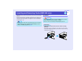
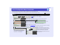
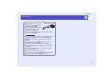
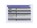
Features of the Projector
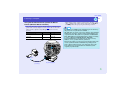
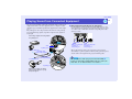
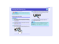
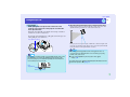
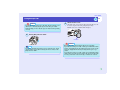
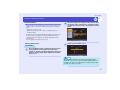
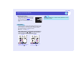
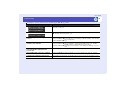
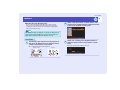
Direct Power On
You can make the projector turn on and be ready to project images simply by
connecting the power cable. You can also turn the power on for projectors in
places such as meeting rooms where the power is centrally controlled, simply
by turning the power on at the central control point. sp.84
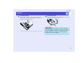
Direct Power Off
After turning the projector off, you can disconnect the power cable right away
to move the projector.
You can also turn the power on to restart the projector immediately after
turning it off. Also, you can turn the power straight off without pressing the
[Power] button. This lets you turn the power off when the projector is in a
meeting room and you operate a breaker switch to centrally turn off the power.
sp.43
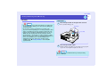
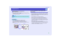
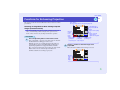
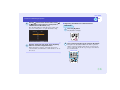
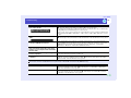
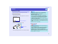
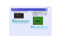
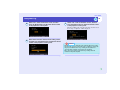
Easy Quick Start Operation (1)
When projection starts, automatic focus operates straight away so that the
images are correctly focused.
The keystone distortion that occurs as result of the projector being tilted
upward or downward can be automatically corrected. sp.34
1
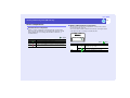
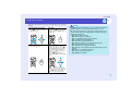
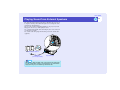
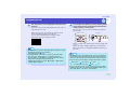
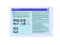
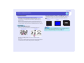
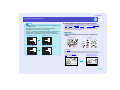
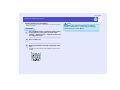
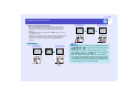
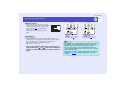
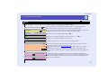
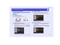
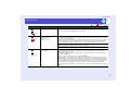
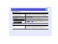
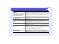
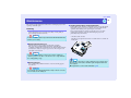
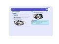
Easy Quick Start Operation (2)
The following easy setup buttons are located at the top of the projector's
control panel. Projected images can be quickly and easily adjusted to the
optimum images just by pressing these buttons.
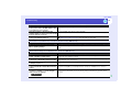
Quick Setup - Optimising the Projection Screen at a Single Touch sp.40
The following functions are carried out all at once to optimise the
projection area. You can also set which functions are carried out at this
time.
• Auto focus
Adjusts the focus.
• Auto Quick Corner
This adjusts distorted images that are projected from the side so that they
are rectangular (4:3 aspect ratio). If using a projection screen (4:3), the
images can fit the screen area exactly.
• Wall Shot
Even if you don't have a screen, you can project images onto some other
surfaces without loss of image color. The projector automatically adjusts
images to their natural colours even when projecting onto surfaces like
blackboards and walls.
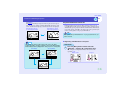
Source Search - Easy Selection of Projection Images - sp.35
This detects image signals from connected equipment. You can change the
projected images each time the button is pressed.
Zoom - Easy Adjustment of Image Size - sp.40
You can adjust the size of the projected images simply by pressing a
button.
User’s Guide
Features of the Projector
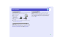
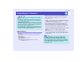
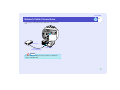
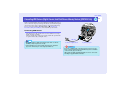
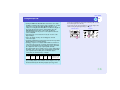
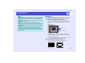
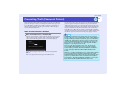
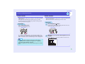
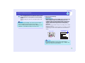
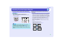
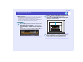
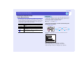
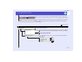
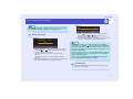
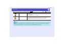
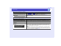
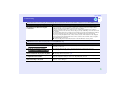
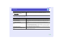
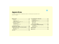
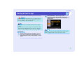
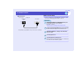
Network Support
When something goes wrong with the projector, such as lamp blowing during
projection, the projector can notify you of the error via e-mail.
In addition, if you are using
EMP-835, EasyMP allows
you to;
• Make easy network
connection with a
computer via a wireless
LAN.
• Project a computer's image
over a network.
sFor instructions on how to use EasyMP, refer to EasyMP Network Setup
Guide and EasyMP Operation Guide.
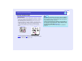
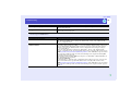
Large-volume USB Storage is Available to Use
(EMP-835 only)
As well as a USB-compatible digital camera, you can use a USB-compatible
hard disc and a USB-compatible memory device. This allows you to make a
presentation in a scenario with large memory. sp.30, "Showing the
Presentation (Using the CardPlayer)" in the EasyMP Operation Guide
2
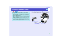
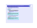
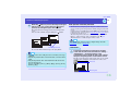
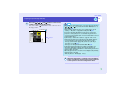
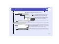
Operation Lock
You can lock the buttons on the projector's control panel and the remote
control.
This function is useful at times such as during show events so that only
projection is carried out deactivating all buttons operation, or in places such as
schools to limit the range of buttons that can be operated. And locking the
remote control buttons is useful to prevent errors in operation while giving
presentations. sp.65
User’s Guide
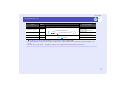
Contents
Features of the Projector .......................................... 1
Before Using the Projector
Part Names and Functions ....................................... 6
Front/Top/Side ............................................................................. 6
Base .............................................................................................. 7
Rear .............................................................................................. 7
Remote Control ............................................................................ 8
Control Panel................................................................................ 9
Input/Output Ports ...................................................................... 10
Before Using the Remote Control ........................... 11
Inserting the Batteries................................................................. 11
Using the Remote Control and Remote Operating Range ......... 12
Installation............................................................... 14
Setting Up the Projector ............................................................. 14
Screen Size and Projection Distance .......................................... 15
Inserting and Removing Cards (EMP-835 only) ..... 16
Installation.................................................................................. 16
Removal ..................................................................................... 17
Access Lamp Statuses ................................................................ 18
Connecting to a Computer ...................................... 19
Eligible Computers..................................................................... 19
Connecting to a Computer.......................................................... 20
Using the Remote Control to Operate the Mouse Pointer
(Wireless Mouse Function) ........................................................ 21
Connecting an External Monitor.............................. 23
Network Cable Connections ................................... 24
Connecting to a Video Source ................................ 25
Projecting Composite Video Images.......................................... 25
Projecting S-Video Images......................................................... 26
Projecting Component Video Images ........................................ 26
Projecting RGB Video Images ................................................... 27
3
Playing Sound from Connected Equipment.............28
Playing Sound from External Speakers...................29
Connecting USB Devices (Digital Camera, Hard
Disk Drive or Memory Devices) (EMP-835 Only) ....30
Connecting USB Devices ...........................................................30
Disconnecting a USB Device from the Projector.......................31
Basic Operations
Turning the Projector On .........................................33
Connecting the Power Cable ......................................................33
Turning the Power On and Projecting Images ...........................34
Adjusting the Position and Size of the Projection Area .............38
One-touch Adjustment of the Projection Area
(Quick Setup)..............................................................................40
Turning the Projector Off .........................................43
Adjusting the Volume...............................................45
Preventing Theft (Password Protect).......................46
When Password Protect is Enabled ............................................46
Entering a Password with the Remote Control...........................47
Setting Password Protect ............................................................48
User’s Guide
4
Contents
Advanced Operations
Functions for Enhancing Projection ........................ 51
Selecting an Image Source While Viewing Projected
Images (Preview Function) ........................................................ 51
Projecting Easy-to-see Images Without a Screen (Wall Shot)... 52
A/V Mute Function .................................................................... 54
Freeze Function .......................................................................... 55
E-Zoom Function ....................................................................... 55
PinP (Picture in Picture) Function.............................................. 56
Pointer Function ......................................................................... 57
Preset Function........................................................................... 59
Changing the Resize/Aspect Ratio ............................................. 61
Projector ID/Remote Control ID ................................................ 63
Operation Button Lock Function................................................ 65
Adjusting Projected Images Manually..................... 67
Focusing the Screen Images (Focus Adjustment) ...................... 67
Manually Correcting Projection Area Distortion (Keystone) .... 67
Adjusting Computer Images....................................................... 73
Selecting the Projection Quality
(Colour Mode Selection) ............................................................ 76
Configuration Menus............................................... 77
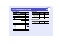
List of Configuration Menu Commands................... 78
Using the Configuration Menus ................................................. 86
Monitoring and Controlling Projectors via a
Network (for the EMP-830) ..................................... 88
Available Network Functions for the EMP-830 ........................ 88
Projector Network Connecting Settings (EMP-830).................. 89
Troubleshooting
Using the Help .........................................................93
Problem Solving ......................................................95
Reading the Indicators ................................................................95
When the Indicators Provide No Help........................................98
Appendices
Maintenance ..........................................................118
Cleaning....................................................................................118
Replacing Consumables ...........................................................119
Saving a User's Logo ............................................124
Optional Accessories and Consumables...............127
Optional Accessories ................................................................127
Consumables.............................................................................127
Glossary ................................................................128
List of ESC/VP21 Commands ...............................131
Command List ..........................................................................131
Communication Protocol..........................................................131
Cable Layouts ...........................................................................131
USB Connection Setup.............................................................132
List of Supported Monitor Displays........................133
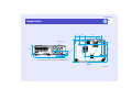
Specifications ........................................................134
Appearance ...........................................................136
Before Using the Projector
This chapter describes the procedures for setting up the projector before use.
Part Names and Functions................................... 6
Connecting to a Computer ................................. 19
• Front/Top/Side.......................................................................6
• Base.........................................................................................7
• Rear ........................................................................................7
• Remote Control .....................................................................8
• Control Panel .........................................................................9
• Input/Output Ports..............................................................10
• Eligible Computers............................................................. 19
• Connecting to a Computer................................................. 20
Before Using the Remote Control ..................... 11
• Inserting the Batteries ........................................................11
• Using the Remote Control and Remote Operating
Range....................................................................................12
Installation ........................................................... 14
• Setting Up the Projector .....................................................14
• Screen Size and Projection Distance..................................15
Inserting and Removing Cards
(EMP-835 only) .................................................... 16
• Installation ...........................................................................16
• Removal................................................................................17
• Access Lamp Statuses .........................................................18
• Card Slot Access Lamp Status ......................................................................18
• Wireless LAN Card Access Lamp Status......................................................18
• If the Monitor Port is a Mini D-Sub 15-pin Port (Example) ........................ 20
• Using the Remote Control to Operate the Mouse Pointer
(Wireless Mouse Function) ................................................ 21
Connecting an External Monitor........................ 23
Network Cable Connections............................... 24
Connecting to a Video Source ........................... 25
• Projecting Composite Video Images ................................. 25
• Projecting S-Video Images................................................. 26
• Projecting Component Video Images ............................... 26
• Projecting RGB Video Images........................................... 27
• If the RGB Output Port is a Mini D-Sub 15-pin Port (Example) ................. 27
Playing Sound from Connected Equipment ..... 28
• When Component Video Signals are being Input......................................... 28
Playing Sound from External Speakers ............ 29
Connecting USB Devices (Digital Camera, Hard
Disk Drive or Memory Devices)
(EMP-835 Only) .................................................... 30
• Connecting USB Devices .................................................... 30
• Disconnecting a USB Device from the Projector ............. 31
User’s Guide
Part Names and Functions
6
Front/Top/Side
• Lamp cover sp.119
• Speaker
Open this cover when replacing the
lamp inside the projector.
• Air exhaust vent
Do not touch during or immediately after
projection, as it can become hot.
• Control panel sp.9
• Handle
Use this handle when carrying the
projector.
• Foot adjust lever sp.39
Pull out the foot adjust lever to extend and
retract the front foot.
• Front adjustable foot sp.39
Extend and retract to adjust the projection angle
when the projector is placed on a surface such
as a shelf.
• Air filter (Air intake vent)
sp.118, p.123
Prevents dust and other foreign particles from
being drawn into the projector. Clean the air
filter periodically.
• Lens cover
Attach when not using the projector in order to prevent
the lens from becoming dirty or damaged.
• Remote control light-receiving
area/sensor sp.12
This receives remote control signals, and
also detects the state of the projection area
for Auto Quick Corner and Wall Shot
operations.
User’s Guide
7
Part Names and Functions
Base
Rear
• Suspension bracket fixing points
(4 points) sp.14, p.127
• Card slot (EMP-835 only)
sp.16
Connect an optional ceiling mount here when
suspending the projector from the ceiling.
Insert a wireless LAN card or
memory card in here when
using EasyMP.
• Input/output ports
sp.10
Use to connect the projector to a
variety of equipment such as a
computer or video equipment.
• Network port sp.24
Connect a network cable here.
• Remote control lightreceiving area
sp.12
Receives signals from the
remote control.
• Security lock ( )
sp.129
• Rear
• Lens cover
cord stopper
Remove when installing
the projector on a ceiling.
Grasp the stopper and
pull it to remove the lens
cover.
• Air filter sp.118, p.123
Prevent dust and other foreign
particles from being drawn into the
projector. Clean the air filter
periodically.
• Air intake vents
sp.118
Clean the air intake vents
periodically.
• Front adjustable foot
• Foot adjust lever
adjustable
foot sp.39
• Power inlet sp.33
Connect the power cable here.
• Rear adjustable foot
sp.39
Extend and retract to adjust the
projection angle when the
projector is placed on a surface
such as a shelf.
User’s Guide
8
Part Names and Functions
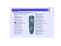
Remote Control
If you position the
over the button icon or button name, a description of that button will appear.
• Remote control light-emitting area sp.12
• [Power] button sp.34, p.43
• Indicator
• [R/C] switch sp.12
• [Page] buttons sp.21
• [A/V Mute] button sp.54
• [E-Zoom] buttons sp.55
• [Resize] button sp.61
• [PinP] button sp.56
• [Freeze] button sp.55
• [Color Mode] button sp.76
•[
• [ ] (illumination) button
• [Pointer] button sp.57
• [Enter( )] button sp.22, p.87, p.93
• [Esc( )] button sp.22, p.87, p.93
• [Menu] button sp.86
• [Help] button sp.93
• [Preview] button sp.51
• Source buttons sp.37
• [Preset] button sp.59
• [Auto] button sp.73
• [Wall Shot] button sp.52
• [Quick Setup] button sp.40
• [Volume] buttons sp.45
• [Num] button sp.47
] button sp.22, p.86, p.93
• [Focus] buttons sp.67
• [Zoom] buttons sp.40
• Numeric keypad sp.47, p.64
• [ID] button sp.64
• [Remote] port sp.127
User’s Guide
9
Part Names and Functions
Control Panel
Buttons with no description are the same as the remote control buttons. Refer to the remote control descriptions for details.
• [Source Search] button sp.35
Operates in the same way as the [Search] button on the remote control.
• [Quick Setup] button sp.40
• [Source] buttons sp.37
[Computer/Component]button: The input source changes in the order of [Computer1/Component]
port → [Computer2/Component] port → EasyMP (EMP-835 only) each time this button is pressed.
[Video/S-Video] button: The input source changes in the order of [S-Video] port → [Video] port
each time this button is pressed.
• [Power] button sp.34, p.43
• [Zoom] buttons sp.40
• [Wall Shot] button sp.52
• [Menu] button sp.86
• Status indicators sp.95
• [Esc] button sp.87, p.93
• [Resize] button sp.61
• [Help] button sp.93
• [A/V Mute] button sp.54
• [Focus] buttons sp.67
• [Volume] button sp.45
• [Shift] button sp.63, p.74, p.75
This button has no function by itself, but is used
when adjusting the sync and tracking and when
using the resize function.
Operates in the same way as the [Esc] button
on the remote control.
• [Enter] button sp.73, p.87, p.93
Operates in the same way as the [Enter] button on the remote control when a
configuration menu or help screen is displayed.
• [ ] and [
] buttons sp.69, p.71, p.75, p.87, p.93
Use these buttons for vertical keystone correction and correction using Quick
Corner.
If you press one of these buttons while holding down the [Shift] button, you can
adjust the syncg of computer analogue images.When pressed while a configuration
menu or help menu is being displayed, these buttons function as [ ] and [ ] (up and
down) buttons for selecting items in the menu.
• [ ] and [ ] buttons sp.69, p.71, p.74, p.87
Use these buttons for horizontal keystone correction and correction using Quick
Corner.
If you press one of these buttons while holding down the [Shift] button, you can
adjust the trackingg of computer analogue images.When pressed while a
configuration menu or help menu is being displayed, these buttons function as [ ]
and [ ] (left and right) buttons for selecting items in the menu.
User’s Guide
10
Part Names and Functions
Input/Output Ports
• [USB TypeA] port (EMP-835 only) sp.30
Connects a digital camera or USB support hard disc/
memory to project their image/movie files or scenarios.
• [USB TypeB] port sp.21, p.132
For an USB cable connection to a computer in order to use
the wireless mouse function when the computer and the
projector are connected using a computer cable.
• [Computer1/Component] port
[Computer2/Component] port sp.20, p.26, p.27
Input analogue-RGB image signals from a computer and RGB-video signals, component
video signals from video equipment.
• [Audio] port (for [Computer1 (or 2)/Component] port) sp.28
Input audio signals from the equipment that is connected to the [Computer1 (or 2)/
Component] port directly above.
• [Control (RS-232C)] port
sp.131
Connects the projector to a computer
using an RS-232C cable. This port is
for control use and should not be used
by the customer.
• [Monitor Out] port sp.23
Outputs analogue-RGB images from a
computer connected by a computer
cable, and RGB-video images from a
video equipment to an external
monitor.
Doesn't support video images and
EasyMP(EMP-835 only).
• [Remote] port
sp.127
Connect the optional
remote control cable set to
input signals from the
remote control.
• [Audio Out] port sp.29
Outputs the audio signals from the
selected source to external speakers.
• [Video] port sp.25
Inputs composite videog signals from a video source.
• [Audio] ports (for [Video] port) sp.28
Input audio signals from the source that is connected to the [Video]
port.
Also input audio signals from the equipment that is connected to the
[Computer2/Component] port if the signal is component video signals.
• [S-Video] port sp.26
Inputs S-Videog signals from a video source.
• [Audio] ports (for [S-Video] port) sp.28
Input audio signals from the source that is connected to the [S-Video]
port.
Also input audio signals from the equipment that is connected to the
[Computer1/Component] port if the signal is component video signals.
User’s Guide
Before Using the Remote Control
Inserting the Batteries
11
2
Insert the batteries.
Check the positions of the (+) and (–) marks inside the battery
holder to ensure that the batteries are inserted the correct way.
3
Replace the battery cover.
Slide the battery cover in until the tab clicks into place.
The batteries are not already inserted into the remote control at the time the
projector is purchased. You will need to insert the batteries that are
provided with the projector before the remote control can be used.
Caution
Be sure to read the Safety Instructions/World-Wide Warranty Terms
before handling the batteries.
PROCEDURE
1
Remove the battery cover.
While pushing down on the rib of the battery cover, slide the
battery cover in the direction of the arrow.
Rib
TIP
If delays in the responsiveness of the remote control occur or if it does
not operate after it has been used for some time, it probably means
that the batteries are becoming flat. If this happens, replace the
batteries with two new AA alkali batteries.
User’s Guide
12
Before Using the Remote Control
Using the Remote Control and Remote Operating
Range
PROCEDURE
1
Set the [R/C] switch to "ON".
Operating angle (vertical)
Operating
distance approx.
10 m (30 ft.)
Operating
distance approx.
10 m (30 ft.)
Approx.
15°
Approx.
15°
Approx.
15°
Approx.
15°
When suspended
from the ceiling
Approx.
15°
Approx.
15°
2
Point the remote control light-emitting area towards
one of the remote control light-receiving areas on the
projector and operate the remote control buttons.
Operating range (horizontal)
Remote control lightreceiving areas
Operating distance
approx. 10 m (30 ft.)
Approx. 30° Approx. 30°
Approx. 30° Approx. 30°
Remote control
light-emitting area
Operating
distance approx.
10 m (30 ft.)
Operating
distance approx.
10 m (30 ft.)
User’s Guide
Before Using the Remote Control
TIP
• Do not allow sunlight or light from fluorescent lamps to shine
directly onto the projector's remote control light-receiving areas,
otherwise it may interfere with the reception of signals from the
remote control.
• When not using the remote control, set the [R/C] switch on the
remote control to "OFF". If you leave the [R/C] switch at "ON", it
will consume battery power.
• If a button on the remote control is pressed down for more than 1
minute while the [R/C] switch is at "ON", the signal for that button
operation will stop being transmitted (the remote control will change
to sleep mode). The purpose of this is to prevent the batteries from
being consumed due to something being placed on top of the remote
control.
When the button is released, normal remote control operation will
resume.
• If it is within a total of about 10 m (30 ft.) in the distance from the
remote control to the screen and from the screen to the projector, the
remote control may work by pointing it towards the screen because
the signals are reflected by the screen and sent to the projector.
However, the operating range varies depending on the status of the
screen.
• If you would like to ensure that remote control operations work
properly from a distance, use the optional remote control cable set to
connect the [Remote] port of the remote control to the projector's
[Remote] port.
s"Appendices: Optional Accessories and Consumables" p.127
13
User’s Guide
Installation
Setting Up the Projector
14
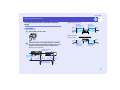
• Front/ceiling projection
The projector supports the following four different projection methods,
allowing you to choose the best method for displaying your images.
Caution
Before setting up the projector, be sure to first read the separate
Safety Instructions/World-Wide Warranty Terms.
• Front projection
• Rear/ceiling projection using a translucent screen
• Rear projection using a translucent screen
* A special method of installation is required for suspending the projector
from the ceiling. Please contact your supplier if you would like to use
this installation method. The optional ceiling mount is required when
installing the projector on the ceiling. s p.127
TIP
When the projector is suspended from a ceiling or projecting from
behind the screen, change the "Extended" - "Projection" setting to
the appropriate setting. sp.83
User’s Guide
15
Installation
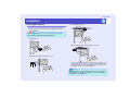
Screen Size and Projection Distance
The distance from the lens to the screen determines the actual image size.
Recommended distance
86–1473 cm (34–580 ft.)
Screen
While referring to the following table, position the projector so that the
images are projected onto the screen at the optimum size. The values
should be used as a guide for setting up the projector. The actual values
will vary depending on projection conditions and the zoom setting.
Units: cm (in.)
Units: cm (ft.)
Projection distance
4:3 Screen size
Shortest
(Wide)
–
Longest
(Tele)
90°
Centre of lens
*
Units: cm (in.)
Vertical distance
from centre of lens
to bottom edge of
screen
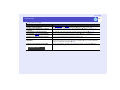
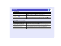
30"
61 × 46
(24.0 × 18.1)
86–142 (34–56)
4 (1.6)
40"
81 × 61
(31.9 × 24.0)
117–192 (46–76)
6 (2.2)
50"
100 × 76
(39.4 × 30.0)
147–241 (58–70)
7 (2.7)
60"
120 × 90
(47.2 × 35.4)
178–290 (70–114)
8 (3.3)
80"
160 × 120
(63.0 × 47.2)
239–389 (94–153)
11 (4.4)
100"
200 × 150
(78.7 × 59.1)
300–487 (118–192)
14 (5.5)
150"
300 × 230
(118.1 × 90.6)
452–734 (178–289)
21 (8.2)
200"
410 × 300
(161.4 × 118.1)
604–980 (238–386)
28 (10.9)
250"
510 × 380
(200.8 × 149.6)
756–1226 (298–483)
35 (13.6)
300"
610 × 460
(240.2 × 181.1)
909–1473 (358–580)
42 (16.4)
* When installing against a wall, leave a space of 20 cm (7.9 in.) or more
between the projector and the wall.
TIP
• The standard lens allows a zoom ratio of up to about 1.6. The image
size at the maximum zoom setting is about 1.6 times bigger than the
image size at the minimum zoom setting.
• When keystone correction is carried out, the projected images will
become smaller. Use the zoom function to adjust the size of the
images if necessary. sp.40
User’s Guide
Inserting and Removing Cards (EMP-835 only)
You can use PC cards such as wireless LAN cards and memory cards with the
EMP-835.
Inserting and removing PC cards will be explained using the included wireless
LAN card provided as an example. When using other cards, or inserting or
removing a card in a PC card slot on a computer, refer to the documentation
included with the card.
TIP
The following PC cards can be inserted into the projector's card slot.
• Wireless LAN card (only compatible with the included accessory)
• Memory card s"Specifications" p.134
16
Installation
Caution
• Insert the PC card facing the right way. Installing the device back to
front or upside down may cause failure or damage.
• Be sure to remove the card before transporting the projector.
PROCEDURE
Insert the PC card into the card slot so that it is facing
upwards.
Insert firmly into the slot until it is secure. Once the wireless LAN
card has been fully inserted in the card slot, the rear edge of the card
will protrude from the slot.
Top
User’s Guide
17
Inserting and Removing Cards (EMP-835 only)
Removal
Caution
PROCEDURE
1
• Do not remove the wireless LAN card while the access lamp of the
wireless LAN card is flashing green, otherwise it may damage the
wireless LAN card.
• Do not remove a memory card while the access lamp of the
projector's card slot is flashing green, or while projecting a scenario.
Doing so may damage the memory card itself or data in the card.
• The PC card gets hot during and immediately after projector use.
Handle the card carefully when removing it from the card slot.
Please handle the card carefully to avoid personal injury or burns.
• When you wish to remove a memory card while using CardPlayer, be
sure to close CardPlayer before removal. CardPlayer may
malfunction if a memory card is removed without closing
CardPlayer first. s"Closing CardPlayer" in the EasyMP
Operation Guide
Press the eject button to the right of the card slot.
The eject button will pop out.
Eject button
Access lamp
2
Press the eject button again.
Enough of the PC card will be ejected so that you can grasp the
edge of the card and pull it straight out of the slot.
Caution
Be sure to press the eject button back in to prevent it from being
broken or damaged.
User’s Guide
18
Inserting and Removing Cards (EMP-835 only)
Access Lamp Statuses
Wireless LAN Card Access Lamp Status
The card slot access lamp does not light when a wireless LAN card has
been inserted into the projector.
You can check the network communication status by observing the status
of the wireless LAN access lamps as described below.
Card Slot Access Lamp Status
When a memory card has been inserted into the card slot of the
projector, you can check the access status for the memory card by
noting whether the access lamp is lit and what colour it is, as
described below.
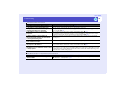
Lit
Off
LINK
Status
Access status
Green
Data is being read from the memory card.
Off
The memory card is in standby state.
Red
An error occurred while data was being read from the memory
card.
ACT
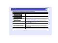
Lit
Lamp
LINK
ACT
Status
flashing
Communication status
Green
The projector is connected to the network and
communication is possible.
Green
Connection to a valid network is in progress.
Green
Data is being transmitted or received.
User’s Guide
Connecting to a Computer
Caution
When connecting the projector to a computer, be sure to check the
following.
• Turn the power off for both the projector and the computer before
connecting them. If the power for either device is on at the time of
connection, damage may result.
• Check the shapes of the cable connectors and the device ports before
making the connections. If you try to force a connector to fit a device
port with a different shape or number of terminals, a malfunction or
damage to the connector or port may result.
• Do not bind the power cable and the connecting cable together. If
the power cable and the connecting cable are bound together, image
interference or errors in operation may result.
Eligible Computers
The method for connecting the projector to a computer using a cable is
explained here.
About network connection with a computer, refer to the following
documentation.
If using the EMP-835
sEasyMP Network Setup Guide.
If using the EMP-830
s"Monitoring and Controlling Projectors via a Network
(for the EMP-830)" p.88
19
The projector cannot be connected to some types of computer, or
projection of images may not be possible even if actual connection is
possible. Make sure that the computer you intend to use satisfies the
conditions given below.
• Condition 1: The computer must have an image signal output port.
Check that the computer has a port such as an "RGB port", "monitor port"
or "CRT port" which can output image signals.
If the computer has a built-in monitor, or if using a laptop computer, it
may not be possible to connect the computer to the projector, or
alternatively you may need to purchase a separate external output port.
Refer to the documentation for your computer under a heading such as
"Connecting an external monitor" or similar for further details.
• Condition 2: The display resolution and frequency of the computer
must be listed in the "List of Supported Monitor Displays"
sp.133
Some computers allow you to change the output resolution, so if
necessary, change the resolution to one that matches a setting in the "List
of Supported Monitor Displays". Refer to the documentation provided
with the computer.
TIP
• You may need to purchase a commercially-available adapter
depending on the shape of the computer's port. Refer to the
documentation provided with the computer for further details.
• If the computer and projector are too far away from each other for
the accessory computer cable to reach, use the optional VGA-HD15
PC cable. s"Appendices: Optional Accessories and
Consumables" p.127
User’s Guide
20
Connecting to a Computer
Connecting to a Computer
The shape and specifications of the computer's monitor port will determine
what type of cable should be used. Select the port and cable in accordance
with the computer being used.
If the Monitor Port is a Mini D-Sub 15-pin Port (Example)
Use the accessory computer cable to make the connections.
To monitor port
Computer cable
(accessory)
To [Computer1/Component] port
(blue) or
[Computer2/Component] port
(blue)
User’s Guide
21
Connecting to a Computer
Using the Remote Control to Operate the Mouse
Pointer (Wireless Mouse Function)
You can use the remote control as a wireless mouse to control the mouse
pointer on the screen by using the accessory USBg cable to connect the
USB port of the computer to the [USB TypeB] port at the rear of the
projector.
Computer
Mouse used
Applicable cable
Windows 98/2000/Me/
XP Home Edition/XP Professional
USB mouse
USB cable
(accessory)
Macintosh
(OS 8.6–9.2/10.1–10.3)
USB mouse
USB cable
(accessory)
To USB port
USB cable
(accessory)
To [USB TypeB] port
* When using the remote control as a wireless mouse, the [Page ] and
[Page ] buttons on the remote control can be used to scroll back and
forth through slides when projecting a PowerPoint presentation.
TIP
• If your projector is EMP-835, the [USB TypeA] port on the back of
the projector does not function as a USB hub.
• The USB cable can only be connected to computers with a standard
USB interface. If using a computer which is running Windows, the
computer must have had a full version of Windows 98/2000/Me/XP
Home Edition/XP Professional installed. If the computer is running
a version of Windows 98/2000/Me/XP Home Edition/XP
Professional that has been upgraded from an earlier version of
Windows, correct operation cannot be guaranteed.
• It may not be possible to use the wireless mouse function under some
versions of both the Windows and Macintosh operating systems.
• Some computer settings may have to be changed in order for the
mouse function to be used. Consult the documentation for the
computer for further details.
User’s Guide
22
Connecting to a Computer
Once the connection has been made, the mouse pointer can be operated as
follows.
Moving the mouse pointer
Left click
Tilt the [ ] button on the remote
control to move the mouse pointer in
the direction of tilt.
Press the [Enter ( )] button.
If you press the [Enter ( )] button twice
in rapid succession, it has the effect of
a double-click.
Right click
Drag and drop
Press the [Esc ( )] button.
When you hold down the [Enter ( )]
button for approximately 1.5 seconds,
the button will light and drag and drop
mode will be enabled. In this mode,
you can carry out drag operations by
tilting the [ ] button.
Press the [Enter ( )] button at the
desired position to drop the items being
dragged.
Drag and drop mode can also be
enabled in the same way by pressing
the [Esc ( )] button for approximately
1.5 seconds. This operation allows
right click dragging and dropping.
TIP
• If the mouse button settings have been reversed at the computer, the
operation of the remote control buttons will also be reversed.
• The wireless mouse function of the remote control cannot be used
while a warning message is being displayed or while the following
functions are being used.
· While Quick Setup is running
· While Password Protect is being set
· While a configuration menu is being displayed
· While a help menu is being displayed
· While the pointer function is being used
· While a sub-screen has been set using the PinP function
· While the E-Zoom function is being used
· While a Quick Corner setting has been made
· While an image is being displayed in real display using the resize
function
· While the preview function is being used
· While a user's logo is being captured
· While Wall Shot is enabled
User’s Guide
Connecting an External Monitor
While projecting analogue RGB images from a computer connected by a
computer cable or projecting RGB-video images from a video equipment, you
can give a presentation viewing the images at an external monitor connected to
the projector.
Connect the external monitor using the cable that is provided with the monitor.
Monitor port
Cable provided with monitor
To [Monitor Out] port (black)
TIP
• Composite video, S-Video and EasyMP (EMP-835 only) images
cannot be output to an external monitor.
• The setting gauge for keystone correction and the configuration
menus and help menus are not output to the external monitor.
• Component video images can be output to an external monitor, but
the colours may not be displayed correctly. (This is normal and is not
a sign of a problem.)
23
User’s Guide
Network Cable Connections
Connect using a commercially-available 100baseTX or 10baseT network
cable.
To network port
To [Network] port
Network cable
(commercially-available)
Caution
To prevent the possibility of incorrect operation, you should use a
category 5 shielded cable.
24
User’s Guide
Connecting to a Video Source
Caution
When connecting the projector to other video sources, take the
following precautions.
• Turn the power off for both the projector and the video source before
connecting them. If the power for either device is on at the time of
connection, damage may result.
• Check the shapes of the cable connectors and the device ports before
making the connections. If you try to force a connector to fit a device
port with a different shape or number of terminals, damage to the
connector or port may result.
• Do not bind the power cable and the connecting cable together. If
the power cable and the connecting cable are bound together, image
interference or errors in operation may result.
25
Projecting Composite Videog Images
Use a commercially-available RCA video cable to make the connections.
To video output port (yellow)
RCA video cable
(commercially-available)
To [Video] port (yellow)
User’s Guide
26
Connecting to a Video Source
Projecting S-Video Images
Projecting Component Video Images
Use a commercially-available S-Videog cable to make the connections.
To component video
output ports
To S-Video output port
S-Video cable
(commercially-available)
Use the optional component videog cable to make the connections.
s"Optional Accessories and Consumables" p.127
To [S-Video] port
Component video cable
(optional)
To [Computer1/Component] port
(blue) or
[Computer2/Component] port
(blue)
User’s Guide
27
Connecting to a Video Source
Projecting RGB Video Images
An RGB video source is a video source other than a computer that outputs
RGB signals.
If the RGB Output Port is a Mini D-Sub 15-pin Port (Example)
Use the accessory computer cable to make the connections.
To RGB output port
Computer cable
(accessory)
To [Computer1/Component] port
(blue) or
[Computer2/Component] port (blue)
User’s Guide
Playing Sound from Connected Equipment
The projector has a built-in speaker with a maximum output of 5 W. You can
output sound from the connected equipment (such as a computer or VCR)
through the projector's built-in speaker if the equipment has an audio output
port.
The [Audio] port to use is the port that is in the same box as the port being
used to input the image signals, except when component video signals are
being input.
28
When Component Video Signals are being Input
If component video signals are being input from a DVD player or some
other equipment to the [Computer 1 (or 2)/Component] port, you can use
one or other of two combinations shown below depending on the audio
cable type you use.
If the image signals are being input to
the [Video] port
When connecting to the
[Computer 2/
Component] port
white
To [Audio] ports
To audio output ports
RCA audio cable
(commercially-available)
To audio output port
Audio cable
(commercially-available)
When connecting to the
[Computer 1/
Component] port
red
When component video images are projected, the connected port is
automatically recognized regardless of which [Audio] port is being used,
and the sound is then output from the projector's built-in speaker.
TIP
• You can adjust the volume after projection has started. sp.45
• If using a commercially- available 2RCA (L/ R)/ stereo mini- jack
audio cable, use one that is marked as "No resistance".
To [Audio] port
When image signals are being
input to the [Computer 1 (or 2)/
Component] port
User’s Guide
Playing Sound from External Speakers
The audio signals from the input source that is currently being projected can
be output to external speakers. When the input source is changed, the audio
signals change automatically too.
You can connect speakers with built-in amplifiers to the projector's [Audio
Out] port in order to enjoy a fuller quality of sound.
Use a commercially-available audio cable with pin jack ⇔ stereo mini jack
(3.5 mm) plugs or similar.
Use an audio cable with a plugs that match the ports for the external audio
equipment.
To external audio equipment
Audio cable
(commercially available)
To [Audio Out] port
TIP
When a stereo mini-jack audio cable is inserted into the [Audio Out]
port, the sound will be output to external speakers. No sound will be
output from the projector's built-in speaker at this time.
29
User’s Guide
Connecting USB Devices (Digital Camera, Hard Disk Drive or Memory Devices) (EMP-835 Only)
USB1.1-compatible digital cameras, hard disk drives and USB storage devices
can be connected to the projector. Image files that are stored inside the digital
camera and scenarios, images and movies that are stored inside USB storage
devices can be played back by EasyMP CardPlayer. s"Showing the
Presentation (Using the CardPlayer)" in the EasyMP Operation Guide
Connecting USB Devices
The following procedure describes how to connect USB devices, using a
digital camera as an example.
Connect a digital camera to the projector using a USB cable provided with,
or specified for use with your digital camera.
USB cable
TIP
• Use a USB cable less than 3m in length. If the cable exceeds 3m,
CardPlayer may not function correctly.
• Check that there is no wireless LAN card or memory card in the
projector's card slot before connecting any USB device.
To USB port of digital camera
To [USB Type A] port
Caution
• If you use a USB hub, the connection may not operate correctly.
Devices such as digital cameras and USB storage devices should be
connected to the projector directly.
• When using an USB-compatible hard disc, be sure to connect the
AC adaptor supplied with the hard disc.
30
User’s Guide
Connecting USB Devices (Digital Camera, Hard Disk Drive or Memory Devices) (EMP-835 Only)
Disconnecting a USB Device from the Projector
After projection is finished, disconnect the USB device from the projector
by the following procedure.
PROCEDURE
1
Position the cursor with the "EJECT" button on the
CardPlayer screen and press the [Enter] button on
the remote control to close CardPlayer. s"Showing
the Presentation (Using the CardPlayer)" in the
EasyMP Operation Guide
Caution
Be sure to shut down CardPlayer first before disconnecting a USB
cable or a USB storage device from the projector. If you do not shut
down CardPlayer before disconnecting the USB device, CardPlayer
may no longer operate correctly.
2
Disconnect the USB cable or USB storage device
from the projector's [USB Type A] port.
Caution
When a USB-compatible hard disk drive is connected, disconnect
the hard disk drive or turn the power for the hard disk drive off
before turning the power for the projector off. If this is not done, it
may cause problems with the projector.
31
Basic Operations
This chapter describes basic operations such as turning projection on and off and adjusting the projected images.
Turning the Projector On.................................... 33
Preventing Theft (Password Protect) ................ 46
• Connecting the Power Cable ..............................................33
• Turning the Power On and Projecting Images .................34
• Adjusting the Position and Size of the Projection Area...38
• When Password Protect is Enabled .................................. 46
• Adjusting the Vertical Position of the Projection Area (Foot Adjustment)...38
• Adjusting the Horizontal Position of the Projection Area ............................39
• Adjusting the Size of the Projection Area
(Zoom Adjustment).......................................................................................40
• Entering a Password with the Remote Control ............... 47
• Setting Password Protect ................................................... 48
• One-touch Adjustment of the Projection Area
(Quick Setup).......................................................................40
Turning the Projector Off ................................... 43
Adjusting the Volume ......................................... 45
• When "Power ON Protect" is Enabled (ON) ................................................ 46
• If the "Timer" Setting is for One Hour or More ........................................... 47
• If "User's Logo Protect" is Enabled (ON)..................................................... 47
User’s Guide
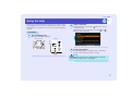
Turning the Projector On
Turn the power on to start projecting images.
33
4
Connect the accessory power cable to the projector.
Check that the power connector is facing the same way as the
power inlet on the projector, and then insert the power cable
connector securely into the projector.
5
Connect the other end of the power cable to an
earthed electrical outlet.
Caution
Be sure to read the Safety Instructions/World-Wide Warranty Terms
before projecting images.
Connecting the Power Cable
PROCEDURE
1
Check that the power is turned off for the projector
and, if necessary, that all components are connected
to the projector.
TIP
2
Connect the computer or other video source to the
projector. sp.19, p.25
3
Remove the lens cover.
Place your fingers against the [ ] and [ ] on the lens cover
and press in while pulling the lens cover forward to remove it.
When "Direct Power ON" in the configuration menu is set to "ON",
the projector's power can be turned on simply by connecting the
power cable.
The default setting is "OFF". s"Extented" - "Operation" p.84
User’s Guide
34
Turning the Projector On
Turning the Power On and Projecting Images
PROCEDURE
1
Check that the Power indicator is lit orange.
2
If using the remote control, set the [R/C] switch on the
remote control to "ON".
3
Press the [Power] button on either the remote control
or the projector's control panel to turn the power on
for the projector.
A beep will sound and the Power indicator will change to
flashing green.
Remote control
Flashing green
Caution
Do not disconnect the power cable or turn off a circuit breaker to turn
the power off directly while the Power indicator is still flashing green,
otherwise it will shorten the lamp's operating life. In addition, the
[Power] buttons on the remote control and the projector's control
panel will be disabled for the same reason.
User’s Guide
35
Turning the Projector On
4
Turn the power on for all equipment connected to the
projector.
For a video source, press the [Play] button at the video source to
start playback if necessary.
5
If no images are projected, press the [Search] button
on the remote control or the [Source Search] button
on the projector's control panel.
The projector detects sources that currently being input and
projects them.
When projection starts, the automatic focus function will
operate and adjustment of the focus will start.
A screen such as that shown below will appear while
adjustment is in progress, but this is normal.
TIP
• If Password Protect has been enabled, the password entry screen will
be displayed when the power is turned on.
Type in the password. sp.47
• Press [Esc] button on the remote control to stop the Auto Focus.
• You can use the "Startup Options" configuration menu to set
functions that are to run when the projector is turned on. You can
change this so that Quick Setup is run instead.
Default setting: Auto Focus is run. s"Setting" -"Quick Setup""Startup Options" sp.80
Remote control
Projector
The type of input source will be displayed at the top-right of the
screen.
When connecting to multiple equipments, press the [Search]
button or the [Source Search] button until the desired image is
projected.
TIP
• When you press the [Search] button or the [Source Search] button,
the projector starts to search incoming image signals from the next
source from the currently-selected source in the order shown below.
The projector projects the images each time it detects those signals.
Computer1
Computer2
EasyMP(EMP-835 Only)
S-Video
Video
The projector skips to the next source when it detects no incoming
signals. If a video device is connected, start playback and then press
the [Search] button or the [Source Search] button.
User’s Guide
36
Turning the Projector On
• If using the EMP-835, EasyMP will be detected as a source while
CardPlayer is running with a memory card or a USB device, or while
Network Screen is activated. While EasyMP standby screen or
setting screen is displayed, the EasyMP screen will not be displayed
by pressing the [Search] or [Source Search] button. Press the
[EasyMP] button on the remote control or the [Computer/
Component] button on the projector's control panel to switch the
source to EasyMP.
• If the input source is not detected correctly, try once more with
different images.
• If the "No Signal." message does not disappear, check the
connections again.
• If an image signal that is not supported is detected, a message will be
displayed and source searching will stop.
• If a laptop computer or a computer with an LCD screen has been
connected to the projector by a computer cable and the images are
not be projected straight away, after starting projection, check that
the computer has been set up to output signals externally.
The following table shows examples of how to toggle output settings.
For details, refer to the section of the documentation provided with
your computer under a heading such as "External output",
"Connecting an external monitor" or similar.
NEC
Panasonic
[Fn]+[F3]
[Fn]+[F3]
Toshiba
IBM
Sony
Fujitsu
[Fn]+[F5] [Fn]+[F7] [Fn]+[F7] [Fn]+[F10]
Macintosh
After startup, change
the Control Panel
adjustment so that
mirroring is active.
• If the same still picture is projected for a long period of time, the
projected image may become burned in on the computer screen. You
should avoid leaving the same image displayed for long periods.
You can press the buttons shown in the following table to select
the desired input source directly.
You can also use the preview function to select the input source
while viewing the input signal images. sp.51
Remote control
Projector
User’s Guide
37
Turning the Projector On
Button to press
Source
EasyMP*1
Remote
control
[EasyMP]
Computer1/Component
[Comp1]
Computer2/Component
[Comp2]
S-Video
[S-Video]
[Video]
Video
On-screen display
Projector
The source changes in the following order each time [Computer/Component] EasyMP
Computer1 (Auto)
is pressed.*2
*3
Computer1 (RGB)
Computer1 (Component Video)
Computer1/Component
Computer2 (Auto)
*3
*1
Computer2 (RGB)
Computer2/Component
Computer2 (Component Video)
*2
The source switches alternately as follows.
S-Video
Video
S-Video
Video
*1 Only changes when using the EMP-835.
sEasyMP Operation Guide and the EasyMP Network Setup Guide for details on using EasyMP.
*2 The input signal will not change to the next signal source unless a button is pressed while the current signal name is still being displayed on the
screen.
*3 The status selected using "Signal" - "Computer1 (or 2) Input" in the configuration menu will be displayed inside brackets.
User’s Guide
38
Turning the Projector On
Adjusting the Position and Size of the Projection Area
Adjusting the Vertical Position of the Projection Area
(Foot Adjustment)
If the images are being projected onto a screen that is higher than the
position of the projector, extend the front adjustable foot to tilt the
projector.
The front adjustable foot and
the rear adjustable feet can be
extended and retracted to
adjust the tilt of the projector to
a maximum of 12° upwards
and 4° downwards.
Caution
Do not tilt the projector any more than 12° upwards or 4 ° downwards
from the horizontal. If the projector is tilted to much, it may fall down
or tip over and injury may result.
TIP
If the projector is tilted vertically, the automatic vertical keystone
correction will operate to automatically correct distortion of the
projected images. Automatic vertical keystone correction can correct
distortion when the projector is tilted up or down within 45°.
Auto V-Keystone is carried out approximately one second after
projection starts. A vertical keystone correction gauge is displayed
while adjustment is in progress.
However, automatic vertical keystone correction will not work in the
following cases
• When the "Projection" configuration menu is set to a setting other
than "Front"
• When keystone correction has been carried out using Auto Quick
Corner or Quick Corner to fit the images within a border
User’s Guide
39
Turning the Projector On
Adjusting the Horizontal Position of the Projection Area
PROCEDURE
While pulling the foot adjust lever at the front of the
projector, lift up the front of the projector to extend the
front adjustable foot.
Extend the front adjustable foot until the desired angle is obtained,
and then release the foot adjust lever.
If the projector cannot be positioned directly in front of the screen, this
adjustment allows projection to be carried out from the side.
To retract the front adjustable foot, gently push down on the projector
while pulling the foot adjust lever.
25°
Foot adjust lever (Front)
If the projector is set up at an angle of within 25° to the left or right of the
projection area, distortion of the images can be corrected by the horizontal
correction function or the Quick Corner correction.
TIP
TIP
If the projector is tilted vertically or horizontally, turn the bases of the
rear adjustable feet to make fine adjustments to the height of the
projector. If the projector is tilted horizontally, the Auto V-Keystone
correction may not work correctly.
Rear
adjustable foot
Extend
Retract
Press the [Quick Setup] button to start "Auto Quick Corner" to
correct the keystone distortion that occurs as result of projecting
from the side of the screen.
s"One-touch Adjustment of the Projection Area (Quick
Setup)" p.40
Correcting the keystone distortion manually by the H/V-Keystone and
Quick Corner function. sp.69, p.71
User’s Guide
40
Turning the Projector On
Adjusting the Size of the Projection Area
(Zoom Adjustment)
The size of the projected images is basically determined by the distance
from the projector to the screen. sp.15
The following procedures explain how to adjust the screen images once the
projector itself has been set up.
TIP
The E-Zoom function can also be used to enlarge parts of the images.
sp.55
PROCEDURE
Press the [Zoom] buttons to adjust the size.
The zoom ratio will change while the buttons are being pressed.
The images can be enlarged to 1.6 times their normal size.
If you would like the images to be larger than this, adjust the projection
distance.
Remote control
Press to
zoom in
Press to
zoom out
Projector
One-touch Adjustment of the Projection Area
(Quick Setup)
Whenever projectors were moved from one place to another, it was usually
necessary to adjust the focus, zoom and keystone distortion each time the
projector was set up in its new position. This projector lets you make the
following adjustments simply by pressing the [Quick Setup] button so that
optimum images can be obtained.
• Focus adjustment for projected images (Auto Focus)
• Keystone correction for projected images (Auto Quick Corner)
This automatically corrects horizontal distortion of the projection area
that occurs when the projector is tilted, and projects the image at an
aspect ratio of 4:3. If using a screen (horizontal to vertical ratio is 4:3) for
projection, this function can be used so that the projection area exactly
fits the size of the screen.
• Colour correction for projected images (Wall Shot)
This automatically adjusts the image colours so that natural colours can
be obtained even when the projection area is not white in colour (such as
a blackboard or wall). Furthermore, it can be used to make shading
adjustments to match the brightness of the room.
User’s Guide
41
Turning the Projector On
TIP
• You can use the "Quick Setup Options" in the configuration menu
to set which functions are carried out when the [Quick Setup] button
is pressed.
Default setting: Auto Focus and Auto Quick Corner are carried out.
Wall Shot is not carried out.
s"Setting" - "Quick Setup" - "Quick Setup Options" p.80
• "Wall Shot" can also be carried out separately by pressing the [Wall
Shot] button on either the remote control or the projector's control
panel. sp.52
• When Quick Setup is used, the adjusted state will be memorised even
after the projector's power is turned off. If you are using the
projector in a single location all the time, you only need to carry out
Quick Setup once, and from then on you do not need to adjust the
projection area.
PROCEDURE
1
Press the [Quick Setup] button on either the remote
control or the projector's control panel.
The message "The Quick Setup is in preparation" will be
displayed and the zoom is adjusted to wide automatically.
projection area so that it fits within the borders of the screen or
board.
Borders
Projection area
If projecting onto a wall surface without using a projection
screen, blackboard or whiteboard, adjust the projection area to
the desired position and size.
2
Press the [Quick Setup] button once more.
Adjustment of the projection area will start.
A screen such as that shown below will appear while
adjustment is in progress, but this is normal.
(While Auto Focus is
being carried out)
(While Auto Quick Corner
is being carried out)
User’s Guide
42
Turning the Projector On
TIP
• You can cancel Quick Setup operation at any time by pressing the
[Esc] button on either the remote control or the projector's control
panel.
• When Auto Quick Corner detects a "frame" (detecting 3 or more
sides, or top and bottom sides, or 2 adjacent sides) within the
projection area, it automatically corrects the image so that it fits
within the "frame" at an aspect ratio of 4:3. The "frame" means the
borders of the screen, whiteboard or blackboard.
When 3 or more sides are
detected
When the frame is
horizontally long
When top and bottom
sides, or 2 adjacent sides
are detected
When no border is
detected
• When running Auto Quick Corner, always be sure to adjust so that
the top edge of the screen is inside the projection area. If the top edge
of the screen is outside the projection area, correction will not be
carried out correctly.
• Auto Quick Corner can provide effective correction when the
borders of the projection surface stand out clearly, such as a white
screen with black borders. If the borders of the projection area do
not stand out clearly, correction may not be carried out correctly. If
projecting onto a surface such as a blackboard, drawing a white box
with chalk as a border, or attaching a sheet of paper as projection
area may help the correct adjustment.
• Auto Quick Corner can be used to carry out correction when the
projector is tilted within the ranges given below. If the projector is
tilted outside these ranges, correction will not be carried out
correctly.
Furthermore, if the projector is tilted both vertically and horizontally
or if the zoom has been adjusted to "W", the correction range will
become narrower than the angles given below.
· When correcting to within a border
Vertically: Approx. 40°Horizontally: Approx. 20°
· When projecting onto a surface without a border
Vertically: Approx. 45°Horizontally: Approx. 15°
• If the distance from the projector to the screen is more than
7.5m,(24.6 ft.) Auto Focus and Auto Quick Corner may not work
correctly. In such cases, adjust the focus manually. s"Adjusting
Projected Images Manually" p.67
• Auto Focus and Auto Quick Corner use sensors in order to work.
These sensors may not work correctly depending on factors such as
the condition of the projection surface and the effects of external
light. If this happens, make the adjustments manually.
s"Adjusting Projected Images Manually" p.67
User’s Guide
Turning the Projector Off
43
Follow the procedure below to turn the projector off.
Caution
PROCEDURE
1
2
Turn the power off for the signal sources that are
connected to the projector.
Check that the power for all connected components has been
turned off.
Press the [Power] button on either the remote control
or the projector's control panel.
The following confirmation message will appear.
If the message "The projector is overheating. Clean or replace the air
filter and lower the room temperature." appears on the screen, press
the [Enter] button on either the remote control or the projector's
control panel to turn the power off and then clean the air filters.
sp.118
3
Press the [Power] button on either the remote control
or the projector's control panel once more.
The lamp will switch off. The Power indicator will change to lit
orange.
Remote control
Changes to lit orange
If you do not want to turn the power off, press a button other
than any of the following:
• At the remote control: [Power], [ ], [ ], [ ], [Num], [ID]
• At the control panel : [Power]
If you do not press any button, the message will disappear
automatically after seven seconds. (The power will not turn off
at this time.)
TIP
• The projector has a direct power off feature. If the projector is
being used in a room such as a meeting room where the power is
controlled centrally, the power can be turned off by operating a
circuit breaker without pressing the [Power] button.
• The projector's power cable can be disconnected immediately after
using the projector and the projector can then be moved.
• If "Standby Mode" in the configuration menu is set to "Network
ON", the exhaust fan will continue operating. This is normal and
does not indicate a problem.
User’s Guide
44
Turning the Projector Off
Caution
You should wait for at least 10 seconds after disconnecting the power
cable before connecting it again. If you connect the power cable
without waiting for 10 seconds, the projector may not start operating
correctly.
4
5
Attach the lens cover.
Attach the lens cover to the lens when not using the projector,
in order to stop the lens from getting dusty or dirty.
Push the lens cover on until it clicks into place.
Set the [R/C] switch to "OFF".
Lens cover
Caution
TIP
If you leave the [R/C] switch on the remote control at "ON", it will
consume battery power. When not using the remote control, set the
[R/C] switch to "OFF".
Note the following points if using the direct power off feature.
• If you disconnect the power cable or turn off a circuit breaker while
using a configuration menu, the settings may not be stored correctly.
Close the configuration menus before using the direct power off
feature.
• If you disconnect the power cable or turn off a circuit breaker while
saving a user's logo, the user's logo may not be saved correctly. If the
user's logo has not been saved correctly, you will need to resave it.
User’s Guide
Adjusting the Volume
You can adjust the volume for the sound from the projector's built-in speaker
or from the external speakers that are connected to the projector.
PROCEDURE
The volume can be adjusted using either the remote control, the projector's
control panel or the configuration menus. This procedure explains how to
use the remote control and the projector's control panel to adjust the
volume.
For adjustment using the configuration menus:
s"Setting" - "Audio" - "Volume" p.82
Press the [Volume] button on either the remote control or
the projector's control panel.
Press the [ ] button to turn up the volume and press the [ ] button to
turn down the volume.
The volume gauge appears on the screen when the volume is being
adjusted.
Remote control
TIP
• If the value displayed in the gauge on the screen stops changing
when the volume is being adjusted, it indicates that the limit for
volume adjustment has been reached.
• The results of volume adjustment are saved separately for each input
source.
45
User’s Guide
Preventing Theft (Password Protect)
When the Password Protect function is enabled, people who do not know the
password cannot project images even though they can turn on the projector's
power. Furthermore, it will not be possible to change the company logo or
other logo that is displayed when the power is turned on. This can help to
increase anti-theft effectiveness.
When Password Protect is Enabled
When "Power ON Protect" is Enabled (ON)
When the power is turned on for the first time after the projector's power
cable is connected to the electrical outlet, or when Direct Power On is
carried out, the following password entry screen will be displayed.
Use the numeric keypad on the remote control to set the password.
sp.47
If the correct password is entered, projection will then start.
46
If you leave the power cable connected to the electrical outlet and turn the
projector's power on when it is in standby mode, projection will start
without the password entry screen appearing. The password entry screen
will only be displayed when the power is turned on for the first time after
the power cable has been disconnected and then reconnected. If Direct
Power On is set to "ON" and you are using a circuit breaker or similar to
centrally control the power, the password entry screen will be displayed the
first time the projector is turned on after the power supply is restored.
TIP
• If an incorrect password is entered three times in succession, the
message "The projector's operation will be locked." will be displayed
for approximately five minutes, and then the projector will switch to
standby mode. If this happens, disconnect the power plug from the
electrical outlet and then reinsert it and turn the projector's power
back on. The screen requesting you to enter the password will be
displayed, so enter the password correctly.
If you forget the password, make a note of the "Request Code:
xxxxx" number that is displayed on the screen, and contact the
nearest address provided at "International Warranty Conditions"
section of the Safety Instructions/World-Wide Warranty Terms
booklet.
• If the above operation should happen to be repeated 30 times without
a correct password being entered, the following message will be
displayed and the projector will accept no more password entry. "The
projector's operation will be locked." Contact the nearest address
provided in the "International Warranty Conditions" section of the
Safety Instructions/World-Wide Warranty Terms booklet.
User’s Guide
47
Preventing Theft (Password Protect)
If the "Timer" Setting is for One Hour or More
The password entry screen will not be displayed at all when the power is
turned on until the length of time that has been set has elapsed. When the
set length of time has elapsed, the password entry screen will be displayed
each time the power is turned on. The length of time referred to here is the
total illumination time for the projector's lamp from the point when the
projector's menu is closed.
If "Timer" is set to "0", the password entry screen will be displayed each
time the power plug is disconnected and reinserted from the electrical
outlet. If the projector's power on when it is in standby mode, the password
entry screen will not be displayed.
If "User's Logo Protect" is Enabled (ON)
If you try to carry out any of the following user's logo-related
operations, a message will be displayed, and the settings cannot be
changed. To change any of the settings, first set "User's Logo
Protect" to "OFF". sp.49
• Capturing a user's logo
• Changing the "Extended" - "Display" - "Display Background" menu
setting or "A/V Mute" setting to "Black" or "Blue" from "Logo", or to
"Logo" from "Black" or "Blue".
• Changing the "Extended" - "Display" - "Startup Screen" menu setting
("ON" or "OFF")
Entering a Password with the Remote Control
Press the [Num] button on the remote control to enter the password.
If you press the [Num] button, it will light up and the remote control
buttons will change to numeric keypad mode so that you can enter
numbers.
If you do not press any button for about 10 seconds while numeric keypad
mode is active, or if you press the [Num] button once more, the [Num]
button will turn off and numeric keypad mode will be cancelled.
Remote control
Numeric keypad
The buttons inside the box will switch
to numeric keypad mode while the
[Num] button is lit.
User’s Guide
48
Preventing Theft (Password Protect)
Setting Password Protect
2
Enable "Power ON Protect".
(1) Select When "Power ON Protect" and then press the
[Enter] button on either the remote control or the
projector's control panel.
(2) Select "ON" and then press the [Enter] button on either the
remote control or the projector's control panel.
(3) Press the [Esc] button on either the remote control or the
projector's control panel.
3
"Timer" setting allows you to specify the time interval
for password prompt.
If you don't use this setting, proceed to step 4.
(1) Select "Timer" and then press the [Enter] button on either
the remote control or the projector's control panel.
(2) After enabling numeric keypad of the remote control, enter
desired hours within the range of 0 to 9999 and press the
[Enter] button on either the remote control or the
projector's control panel.
Press the [Esc] button on either the remote control or the
projector's control panel to reenter the time.
The elapsed time counter will start counting once the
Password Protect setting menu is exited.
Follow the procedure below to make Password Protect settings.
PROCEDURE
1
Press the [Freeze] button on the remote control for
approximately five seconds.
If using the projector's control panel, hold down the
[ ] button and press the [Menu] button for
approximately five seconds.
The Password Protect menu will be displayed.
Remote control
TIP
• If Password Protect has already been enabled, the screen requesting
a password will be displayed.
If the correct password is entered, the Password Protect setting menu
will be displayed. s"When Password Protect is Enabled" p.46
• When Password Protect has been set to "ON", attach the Password
Protect sticker to your preferred place on the projector to increase
anti-theft effectiveness.
User’s Guide
49
Preventing Theft (Password Protect)
4
5
Enable "User's Logo Protect".
(1) Select "User's Logo Protect" and then press the [Enter]
button on either the remote control or the projector's
control panel.
(2) Select "ON" and then press the [Enter] button on either the
remote control or the projector's control panel.
(3) Press the [Esc] button on either the remote control or the
projector's control panel.
Enter the password.
(1) Select "Password" and press the [Enter] button on either
the remote control or the projector's control panel.
(2) When the message "Change the password?" is displayed,
select "Yes" and then press the [Enter] button on either the
remote control or the projector's control panel.
The default setting for the password is "0000", and you can
change it to the required password.
If you select "No", the display will return to the screen in
step 1.
(3) Enables numeric keypad of the remote control and enter a
4-digit password.
The password entered will be displayed as "****".
Once four digits have been entered, the confirmation
screen will be displayed.
(4) Re-enter the password to confirm.
The message "The new password is stored." will be
displayed.
If you enter the password incorrectly, a message will be
displayed prompting you to re-enter the password.
6
Once the settings are complete, press the [Menu]
button.
TIP
• When the set time has elapsed and the password is entered,
projection will start and the "Time-elapsed" counter will be cleared
to count again.
• Make a note of the password so that you do not forget it and keep it
in a safe place.
• If you lose the remote control, you will not be able to enter the
password. Keep the remote control in a safe place at all times.
Advanced Operations
This chapter describes functions for enhancing the projection of images, and how to use the configuration menus.
Functions for Enhancing Projection ................. 51
• Selecting an Image Source While Viewing Projected
Images (Preview Function).................................................51
• Projecting Easy-to-see Images Without a Screen
(Wall Shot) ...........................................................................52
• A/V Mute Function .............................................................54
• Freeze Function ...................................................................55
• E-Zoom Function ................................................................55
• PinP (Picture in Picture) Function ....................................56
• Pointer Function..................................................................57
• Preset Function....................................................................59
• Storing Setting Values ...................................................................................59
• Applying Preset Settings ...............................................................................60
• Changing the Resize/Aspect Ratio.....................................61
• Selecting the Computer Display Method ......................................................61
• Projecting Wide-screen Images from Video Equipment...............................62
• Projector ID/Remote Control ID .......................................63
• Registering an ID Number for a Projector ....................................................63
• Registering an ID Number for a Remote Control .........................................64
• Operation Button Lock Function ......................................65
• Locking the Control Panel Buttons ...............................................................65
• Locking the Remote Control Buttons ...........................................................66
Adjusting Projected Images Manually .............. 67
• Focusing the Screen Images (Focus Adjustment).............67
• Manually Correcting Projection Area Distortion
(Keystone)............................................................................ 67
• Vertical and Horizontal Correction............................................................... 69
• Height Correction ......................................................................................... 70
• Correcting Keystone Distortion so that the Projection Area Fits the Screen
Exactly (Quick Corner)................................................................................. 71
• Adjusting Computer Images ............................................. 73
• Automatic Setup ........................................................................................... 73
• Adjusting the Tracking ................................................................................. 74
• Adjusting the Sync........................................................................................ 75
• Selecting the Projection Quality
(Colour Mode Selection) .................................................... 76
Configuration Menus .......................................... 77
List of Configuration Menu Commands ............ 78
• Using the Configuration Menus ........................................ 86
Monitoring and Controlling Projectors via a
Network (for the EMP-830).................................. 88
• Available Network Functions for the EMP-830 ............... 88
• Monitoring Function Using SNMP and the SNMP Manager Program ........ 88
• Monitoring and Control Functions Using the Accessory Software.............. 88
• Using a Network for Monitoring and Control .............................................. 89
• Projector Network Connecting Settings (EMP-830) ....... 89
User’s Guide
Functions for Enhancing Projection
51
This section describes the various useful functions that can be used to enhance
presentations.
Active window
Shows the images that are currently being projected.
Computer (Analog-RGB)
Selecting an Image Source While Viewing Projected
Images (Preview Function)
If using EMP-835, a
image of EasyMP will
appear
You can momentarily project images from the currently-selected input
source, and switch images while viewing them in a preview screen.
Use the remote control to carry out all preview function operations.
Easy MP
Move the
red box
to the
target
image.
PROCEDURE
1
Press the [Preview] button on the remote control.
After a short while, a preview screen such as the one shown in
the illustration below will appear on the screen.
When the preview screen is being displayed, the frames for
ports that have no image signal being input or which have a
signal being input that is not supported will be solid blue.
Once you select an input source by pressing any of the Search
buttons on the remote control, the preview function is
terminated and the selected image is projected.
Computer
Images from the
[Computer1/
Component] port
2
Computer
S-Video
Video
Images from the [Video]
port
* A blue screen will
appear when no
signals are being input.
Images from the Images from the
[Computer2/
[S-Video] port
Component] port
Tilt the [ ] button to select the images to be
projected.
Move the red box until the desired image is selected.
Computer (Analog-RGB)
Move the
red box
to the
target
image.
Easy MP
Computer
Computer
S-Video
Video
User’s Guide
52
Functions for Enhancing Projection
3
Press the [Enter] button.
The selected images are then projected in the active window.
If you press the [Enter] button once more, the preview function
is cancelled and the images in the active window are projected.
To return to the images that were being projected before the
preview function was activated, press the [Esc] or [Preview]
button.
S-Video
Easy MP
Computer
Computer
S-Video
Projecting Easy-to-see Images Without a Screen
(Wall Shot)
When the Wall Shot function is used, images can be projected without loss
of original colour even onto surfaces such as blackboards and coloured
wall surfaces which are being used instead of a screen.
For example, if projecting onto a green blackboard, the projected images
would normally appear greenish and be very difficult to see. The Wall Shot
function uses a sensor to measure the condition of the projection surface
and automatically adjusts the colour of the projected images based on these
measurements.
The Wall Shot function also allows shading to be adjusted. If projecting
onto a screen that is located near a window, the Wall Shot function can be
used to obtain clear images when they might otherwise appear faded.
Video
TIP
TIP
• You can hear the sound for the images in the active window while
the preview window is being displayed.
• Images other than the image in the active window will be projected
as still images.
• If you press the [Preview] button while E-Zoom function is active or
real display is being used, these functions will be cancelled and the
preview screen will be displayed. If you cancel the preview function
without changing the input source, the projected images will return
to the state they were at before the preview function was activated.
• Wall Shot can be used for adjustment if the projection distance is
within approximately 86–750 cm (2.8–24.6 ft.). However, this
distance will vary depending on the condition of the projected
surface, for instance if the projection surface is an extremely
reflective surface such as a whiteboard, or if it is a highly nonreflective surface such as a dark wall.
• The sensor may not be able to correctly measure the condition of the
projection surface if you are projecting on a striped or patterned
wall. In this event, Wall Shot may not be able to correctly adjust the
color of the projected images.
User’s Guide
53
Functions for Enhancing Projection
PROCEDURE
The Wall Shot function can be operated using either the remote control or
the projector's control panel.
1
Press the [Wall Shot] button on either the remote
control or the projector's control panel while the
images are being projected.
When the button is pressed, the current status is displayed on
the screen.
Remote control
3
Once the measurement is finished and colour
correction is complete, the images will be projected
in the corrected condition.
To cancel the correction, press the [Wall Shot] button while
"Wall Shot ON" is being displayed on the screen so that "Wall
Shot OFF" is selected.
TIP
• When the projector's power is turned off, images will be projected
next time with the status set to "Wall Shot OFF". However, the
correction values that were obtained by the previous measurement
operation will be stored even when the power is turned off.
If projecting in the same location as before, you can retrieve the
colour correction values that were used previously (the five seconds
required for readjustment will not be necessary).
The status will change as follows each time the [Wall Shot] button is
pressed.
Wall Shot OFF
2
To change the status, press the [Wall Shot] button
while the status is being displayed on the screen.
For example, if you press the [Wall Shot] button while "Wall
Shot OFF" is displayed, the status will change to "Wall Shot
ON" and measurement of the projection surface will start.
Colours in the order red → green → blue → black will be
projected for approximately five seconds while measurement is
in progress.
Wall Shot ON
Wall Shot Memory Call
When "Wall Shot Memory Call" is selected, the previous adjustment
values are retrieved.
• If you change the projection location or change the condition of the
projection surface, you should repeat the Wall Shot measurements.
If you press the [Wall Shot] button twice while "Wall Shot ON" is
being displayed, "Wall Shot Readjustment" will be displayed and
adjustment will then start.
Wall Shot ON
Wall Shot OFF
Wall Shot Readjustment
User’s Guide
54
Functions for Enhancing Projection
A/V Mute Function
This function momentarily pauses the images and sound.
For example, it can be used when you do not wish to show details of
operations such as selecting different files while computer images are
being projected.
However, if you use this function when projecting moving images, the
images and sound will still continue to be played back by the source, and
you cannot return to the point where the A/V Mute function was activated.
Solid black
Solid blue
User's logo
Default setting
PROCEDURE
Press the [A/V Mute] button.
The images and sound will then be momentarily turned off.
Remote control
You can use "Extended" - "Display" - "A/V Mute" in the
configuration menu to select one of the following three displays to
appear when the pictures and sound is momentarily turned off.
sp.83
Projector
Press the [A/V Mute] button once more to continue normal
projection.
You can also continue normal projection by pressing the [Esc] button
on either the remote control or the projector's control panel.
TIP
The default user's logo is the EPSON logo. You can change the user's
logo by recording and setting your own logo. sp.124
User’s Guide
55
Functions for Enhancing Projection
Freeze Function
This function pauses only the projected images. The sound keeps playing
without pausing.
The signal source will still be playing back the images even while
projection is paused, and so it will not be possible to resume projection
from the point where it was paused.
PROCEDURE
Press the [Freeze] button.
The images will then be paused.
E-Zoom Function
You can use this function to enlarge portions of graphs and tables that you
want to see more closely.
The E-Zoom function is controlled using the remote control.
PROCEDURE
1
Remote control
Remote control
To continue projecting the images, press the [Freeze] button once
more. You can also continue normal projection by pressing the [Esc]
button on either the remote control or the projector's control panel.
Press the [E-Zoom ] button.
A cursor (cross) indicating the centre point for the area to be
enlarged will appear on the screen.
2
Move the cross to the area of the image that is to be
enlarged.
Tilt the [ ] button on the remote control to move the cross.
TIP
• If you press the [Freeze] button on the remote control while a
configuration menu or help menu is displayed, the configuration
menu and help menu display is cancelled.
• The Freeze function also works while the E-Zoom function is being
used.
Cross
User’s Guide
56
Functions for Enhancing Projection
3
When the [ ] button is pressed, the image is enlarged
with the cross at its centre. When the [ ] button is
pressed, the enlarged image is then reduced.
The enlargement ratio will appear at the bottom-right of the
screen.
You can scroll around the image by tilting the [ ] button.
PinP (Picture in Picture) Function
This function lets you display separate images in a smaller screen (subscreen) over the top of the images that are currently being projected (main
screen).
Computer images or EasyMP images (for the EMP-835) can be displayed
in the main screen , and video images (composite videog or S-Videog) can
be displayed in the sub-screen.
The video images in the sub-screen are selected using "Setting" - "PinP
Options" - "Subscreen Image" in the configuration menu. sp.82
The PinP function is controlled using the remote control.
TIP
The PinP function cannot be used for computer images when the
refresh rateg is set to "interlacedg".
Shows enlargement ratio
PROCEDURE
To cancel the E-Zoom function, press the [Esc] button.
TIP
• The selected area can be enlarged to between 1–4 times, in 25 steps
of × 0.125.
• The E-Zoom function will be cancelled when the zoom ratio returns
to × 1.
• The following buttons can be used while E-Zoom has been used to
increase the image size.
[Power] , [A/V Mute] , [Freeze] , [Menu] , [Help] , [Focus] , [Zoom] ,
[Pointer] , [Page]
1
Connect the equipment for projecting to the main
screen and the sub-screen, and then use "Setting" "PinP Options" - "Subscreen Image" in the
configuration menu to make the sub-screen settings,
then press the [PinP] button on the remote control.
The sub-screen will appear at the top-left of the screen, and the
operation guide will appear at the bottom-left of the screen.
Sub-screen
Operation guide
User’s Guide
57
Functions for Enhancing Projection
2
Tilt the [ ] button on the remote control to change
the position of the sub-screen.
Pointer Function
You can use this function to display a pointer icon on the images that are
being projected, and use the remote control to control it.
The pointer icon can be used to indicate parts of an image that is being
projected to clarify which part is being described or to draw attention to it.
TIP
You can use the "Setting" - "Pointer" configuration menu to set the
type, size and movement speed for the pointer. sp.82
3
When you press the [Enter] button, the operation
guide screen will disappear and the sub-screen
display position will be set.
To cancel the PinP function, press the [PinP] button once more.
TIP
• The position of the sub-screen is memorised, so that the sub-screen
will appear in the last position which was set next time the PinP
function is used.
• To switch between sound for the main screen and the sub-screen, use
"Setting" - "PinP Options" - "Audio Output" in the configuration
menu.
PROCEDURE
1
Press the [Pointer] button.
The pointer will be displayed in the centre of the screen.
Remote control
User’s Guide
Functions for Enhancing Projection
2
Tilt the [ ] button to move the pointer.
Press the [Pointer] button again to cancel the pointer. The
pointer will then disappear.
Pointer
58
User’s Guide
59
Functions for Enhancing Projection
Preset Function
2
Once the settings are complete, select "Preset" from
the "Signal" menu and then press the [Enter] button
on either the remote control or the projector's control
panel.
3
Select a preset number (1 to 5).
While projecting analogue RGB images from a computer connected via a
computer cable, you can store the following settings in the configuration
menu.
• All items in the "Image" menu
• All items in the "Signal" menu except for "Computer1 Input" and
"Computer2 Input"
If settings are stored for signals with different resolutions and frequencies,
the preset values can be applied to the analogue RGB signals that are
currently being projected simply by pressing the [Preset] button on the
remote control.
Up to five groups of the settings can be stored.
Storing Setting Values
PROCEDURE
1
Press the [Menu] button on either the remote control
or the projector's control panel, and then select
"Image" or "Signal" from the configuration menu. The
mode for storing setting details will then be enabled.
sp.78, p.79
TIP
The preset numbers that have an input resolution displayed have
already been set. If you select a preset number that has already been
set and use it to save the current settings, the existing settings in that
recording area will be overwritten.
User’s Guide
60
Functions for Enhancing Projection
4
Press the [Enter] button on either the remote control
or the projector's control panel to store the setting
values.
When the settings have been saved, the input resolution will
appear.
TIP
• To clear the memorised details, select "Reset" from the "Signal"
menu. Note that this will clear all of the preset settings.
• Preset recording is possible regardless of whether Wall Shot is ON or
OFF. However, the Wall Shot settings are not memorised.
Applying Preset Settings
PROCEDURE
While images from analogue RGB signals are being input
from a computer which is connected by means of a
computer cable, press the [Preset] button on the remote
control to apply the preset settings for the "Image" or
"Signal" menu to the images that are currently being
projected.
The memorised preset number changes in ascending order each time
the button is pressed.
You must press the [Preset] button while the preset number and input
resolution appear on the screen, otherwise the selection will not
change.
Remote control
Preset number and input
resolution appear
TIP
• Preset numbers that have not yet been preset will be skipped.
• If no preset settings have been made, the message "No Entry" will
appear when you press the [Preset] button.
User’s Guide
61
Functions for Enhancing Projection
If the input resolution is lower than the panel resolution (1024 × 768)
Changing the Resize/Aspect Ratio
You cannot switch to real display or change the aspect ratio while EasyMP
is running (EMP-835 only).
Resized display
Real display
Selecting the Computer Display Method
When projecting computer images, the display method can be changed
between resized display (in which the images are projected so that they fill
the available projection area) and real display (in which the images are
projected at the resolution of the original input signal).
The default setting is the resized display.
If the input resolution is higher than the panel resolution (1024 × 768)
PROCEDURE
The display switches between real display and resized
display each time you press the [Resize] button.
Remote control
The image is projected in the
middle of the screen at the original
input signal resolution.
Resized display
Real display
Projector
The middle section of the image is
projected. You can tilt the [ ]
button on the remote control to
scroll around the image.
User’s Guide
62
Functions for Enhancing Projection
TIP
• The type of display for projected images can be saved separately for
each input source.
• If the input resolution is the same as the panel resolution
(1024×768 dots), the image size will not change.
• In the case of SXGA (5:4) input signals, the image position changes
as shown below each time you press the [Resize] button while
holding down the [Shift] button on the projector's control panel.
Resized display (5:4)
Aligned to left (5:4)
Projecting Wide-screen Images from Video Equipment
You can switch the aspect ratiog between 4:3 and 16:9 when component
videog (YCbCrg and YPbPrg), S-Videog and composite videog signals
are being projected.
Images that have been recorded in digital video and DVD images can be
projected in 16:9 wide-screen format.
PROCEDURE
The display switches each time you press the [Resize]
button.
Remote control
Resized display (4:3)
Projector
Aligned to right (5:4)
For SDTVg
When 16:9 format images in squeeze mode are projected at 4:3 aspect
ratio, the images are squeezed horizontally and appear vertically elongated.
When images in squeeze
modeg are projected at 4:3
When images in squeeze
mode are projected at 16:9
User’s Guide
63
Functions for Enhancing Projection
For HDTVg
When 16:9 format images in squeeze mode are projected at 4:3 aspect
ratio, the images are resized so that they fill the full vertical area of the
screen, and the left and right edges are truncated and are not displayed.
When images in squeeze
mode are projected at 16:9
When images in squeeze
mode are projected at 4:3
Projector ID/Remote Control ID
If using more than one projector at a time, such as at a show, you can
record ID numbers for the projectors and for the remote controls in order to
simultaneously operate projectors with the same ID number. Alternatively,
if you set the remote control ID to "0", all projectors can be operated by the
remote control regardless of the projector ID numbers.
TIP
The default values for ID numbers are "1" for projectors and "0" for
remote controls.
Registering an ID Number for a Projector
TIP
When projecting images with an aspect ratio of 16:9, the image
position will change as follows each time you press the [Resize] button
while holding down the [Shift] button on the projector's control panel.
Centre display
Top edge display
PROCEDURE
1
Press the [Menu] button and then select the
"Extended" - "Projector ID" configuration menu.
s"Using the Configuration Menus" for details on this
operation. p.86
Remote control
Bottom edge display
Projector
User’s Guide
64
Functions for Enhancing Projection
2
Use the [ ] button on the remote control or the [ ]
or [ ] button on the projector's control panel to
select the desired ID number (1–9).
Press the [Enter] button on either the remote control or the
projector's control panel to accept the ID number setting.
Registering an ID Number for a Remote Control
PROCEDURE
1
Press the [ID] button.
The [ID] button will light.
Remote control
3
Once the setting has been made, press the [Menu]
button to close the configuration menu.
When registration is complete, only signals from remote
controls with the same ID number or an ID number of "0" can
be received.
2
Press a button from [0] to [9] to specify an ID number.
The light for the [ID] button will turn off and the registration
will be complete. If a number other than "0" is registered, the
remote control will only be able to operate projectors that have
the same ID number.
Remote control
User’s Guide
65
Functions for Enhancing Projection
TIP
2
If you would like to check the ID number that is currently set for a
remote control, press the [ID] button on the remote control so that the
button lights, and then press the [ID] button once more. After a brief
period, the [ID] button will flash, and the number of flashes will equal
the remote control's ID number.
Set to "Full Lock" or "Partial Lock".
If set to "Full Lock", none of the buttons on the control panel
except the [Power] button can be operated.
If set to "Partial Lock", all buttons other than the Quick Setup
buttons will be disabled and cannot be used.
Quick Setup buttons
Operation Button Lock Function
This function locks the buttons on the projector's control panel and the
remote control.
• Locking the control panel button
This function is useful at times such as during show events so that only
projection is carried out deactivating all buttons operation, or in places
such as schools to limit the range of buttons that can be operated.
• Locking the remote control buttons
You can lock the buttons that are related to making adjustments in order
to prevent errors in operation while giving presentations.
Locking the Control Panel Buttons
You can either lock all of the control panel buttons or only some of them.
PROCEDURE
1
Press the [Menu] button on either the remote control
or the projector's control panel, and then select
"Setting" - "Operation Lock" - "Control Panel" from
the configuration menu.
3
When the confirmation message is displayed, select
"Yes".
The control panel buttons will be locked in accordance with the
selected setting.
TIP
There are two methods to cancel the projector's control panel lock.
• Using remote control, change the "Setting" - "Operation Lock" "Control Panel" in the configuration menu to "OFF".
• Hold down the projector's [Enter] button continuously for about 7
seconds, a message will be displayed and the lock will be cancelled.
User’s Guide
66
Functions for Enhancing Projection
Locking the Remote Control Buttons
You can lock some of the remote control buttons to prevent mis-operations
during presentations.
PROCEDURE
1
Press the [Menu] button on either the remote control
or the projector's control panel, and then select
"Setting" - "Operation Lock" - "Remote Control" from
the configuration menu.
2
Set to "Partial Lock".
3
When the confirmation message is displayed, select
"Yes".
The buttons shown in the box in the illustration below will be
disabled.
Remote control
TIP
To cancel the remote control button lock function, change the
"Setting" - "Operation Lock" - "Remote Control" setting in the
configuration menu to "OFF". sp.81
User’s Guide
Adjusting Projected Images Manually
Focusing the Screen Images (Focus Adjustment)
PROCEDURE
Press the [Focus] button to adjust the focus.
The images may lose their focus when keystone correction and
sharpness are adjusted.
Remote control
Projector
TIP
• If the surface of the lens is dirty or misted over as a result of
condensation, it may not be possible to adjust the focus correctly. If
this happens, clean or de-mist the lens. sp.102, p.118
• If the projection distance is outside the range of 86 – 1473 cm (33.9–
579.9 in.), the focus cannot be adjusted correctly. Check the projection
distance.
67
Manually Correcting Projection Area Distortion
(Keystone)
This projector is equipped with an "Auto V-keystone" function that detects
vertical tilt of the projector and automatically corrects the vertical keystone
distortion of the projected image when staring projection. Furthermore,
horizontal keystone distortion caused by tilting the projector horizontally
can also be corrected using the "Auto Quick Corner" function. Auto Quick
Corner is carried out when the [Quick Setup] button is pressed. s"Onetouch Adjustment of the Projection Area (Quick Setup)" p.40
If you would like to make fine adjustments to the results of automatic
vertical keystone correction or Auto Quick Corner, you can carry out
keystone correction manually.
This projector is equipped with the following two keystone correction
functions.
• Vertical and horizontal correction
s"Vertical and Horizontal Correction" p.69
s"Height Correction" p.70
User’s Guide
68
Adjusting Projected Images Manually
• Quick Corner:
This correction function is used when both horizontal and vertical
keystone distortion occurs in the projection area to adjust the projection
area so that it fits the screen exactly. sp.71
The above correction method is selected automatically when automatic
vertical keystone correction and Auto Quick Corner are carried out. The
selection conditions are as follows.
• When only automatic vertical keystone correction is carried out, or when
Auto Quick Corner is carried out for a projection surface such as a wall
that has no borders.
H/V-Keystone is selected. The setting in the "Keystone" configuration
menu will also change.
• When the screen has a border and Auto Quick Corner is selected
Quick Corner is selected. The setting in the "Keystone" configuration
menu will also change.
• When Auto Quick Corner is not carried out
Correction is carried out according to the setting in the "Keystone"
configuration menu.
TIP
• Vertical keystone correction can be carried out if the vertical angle
of tilt is within approximately 45°. Horizontal keystone correction
can be carried out if the horizontal angle of tilt is within
approximately 25°. However, the corresponding angle will be smaller
under any of the following conditions.
· If the projector is tilted both vertically and horizontally
· If the zoom has been adjusted to "W"
• The larger the angle of tilt, the poorer the focus of the contours in
the projected images will become.
• If a large amount of keystone correction is applied, fine details such
as text characters and lines may go out of focus.
• Keystone corrections that have been applied using the keystone
correction functions are memorised even when the projector's power
is turned off. If you have changed the projection position or angle,
you will need to repeat the correction procedure.
• When keystone correction is carried out, the projected images will
become smaller. Use the zoom function to adjust the size of the
images if necessary. sp.40
• If the images become uneven in appearance after keystone
correction is carried out, decrease the sharpness. sp.78
User’s Guide
69
Adjusting Projected Images Manually
Vertical and Horizontal Correction
Vertical and horizontal correction can be carried out using either the
projector's control panel or the configuration menus. This procedure
explains how to use the projector's control panel to correct keystone
distortion.
For adjustment using the configuration menus: s"Setting" - "Keystone" "H/V-Keystone" p.81
"H-Keystone" and "Height" cannot be used at the same time. If you use the
horizontal correction function when height correction adjustment has
already been carried out, the height correction adjustment will be
cancelled.
PROCEDURE
If the top of the
image is elongated
Projector
If the left edge of the
image is elongated
If the right edge of the
image is elongated
Projector
Projector
TIP
If the bottom of the
image is elongated
Projector
• If the "Quick Corner" correction screen is displayed when pressing
the [ ], [ ], [ ] or [ ], the "Quick Corner" is currently selected.
s p.71
When carrying out vertical correction and horizontal correction,
select "Setting" - "Keystone" - "H/V-Keystone" in the configuration
menu and then make the correction.s p.81
• If the value displayed in the gauge on the screen stops changing
when vertical correction and horizontal correction is being carried
out, it indicates that the limit for vertical correction and horizontal
correction has been exceeded. Check that the projector has not been
set up at an angle which exceeds the proper limit.
User’s Guide
70
Adjusting Projected Images Manually
Height Correction
When vertical keystone correction is carried out automatically or manually,
the height of the projected images will become shorter. Use the height
correction function to adjust the height of the projection area.
The height correction function is accessible from the configuration menu.
This cannot be set when horizontal correction is carried out.
2
Tilt the [ ] button on the remote control to the left or
right, or press the [ ] or [ ] buttons on the
projector's control panel to correct the height while
viewing the projected images.
3
When the adjustment is complete, press the [Menu]
button on the remote control or the projector's
control panel to close the configuration menu.
PROCEDURE
1
Press the [Menu] button on either the remote control
or the projector's control panel.
Then select "Setting" - Keystone" - "H/V-Keystone" "Horz./Vert./Height" - "Height" from the configuration
menu.
For details, refer to "Using the Configuration Menus" sp.86
User’s Guide
71
Adjusting Projected Images Manually
Correcting Keystone Distortion so that the Projection
Area Fits the Screen Exactly (Quick Corner)
Quick Corner correction can be carried out using either the projector's
control panel or the configuration menus. This procedure explains how to
use the projector's control panel to correct keystone distortion.
If using the configuration menu: s"Setting" - "Keystone" - "Quick
Corner" p.81
PROCEDURE
1
Press any one of the [ ], [ ], [ ] or [ ] buttons on
the projector's control panel.
The Quick Corner correction screen will be displayed.
2
Press the [Enter] button on the projector's control
panel and then select the corner to be corrected on
the screen.
You can also press the [Enter] button on the remote control to
select the corner.
The selected
angle will
appear yellow.
User’s Guide
72
Adjusting Projected Images Manually
3
Press the [ ], [ ], [ ] and [ ] buttons on the remote
control to correct the angle position.
You can also tilt the [ ] button on the remote control to correct
the angle position.
Screen
TIP
• If the vertical or horizontal keystone correction gauge appears when
[ ], [ ], [ ] or [ ], is pressed, it means that "H/V-Keystone" is
selected. sp.69
When carrying out Quick Corner, select "Quick Corner" in the
"Setting" - "Keystone" configuration menu first. sp.81
• If you press down the [Esc] button on the remote control or the
projector's control panel for one second while the Quick Corner
correction screen is displayed, the correction results will be restored
to their default values.
• If the message "Cannot move anymore." appears on the screen
while using the Quick Corner function, it means that the limit for
correction has been reached. Check the following two points.
· Is the projection distance appropriate for the size of the target
projection screen? sp.15
· Is the projector tilted past its maximum limit? sp.67
• If the input signal is interrupted or an image signal that is not
supported is input while using the Quick Corner function, the
correction value at that point will be recorded and the Quick Corner
function will be cancelled.
• When the Quick Corner correction screen is displayed, the following
functions will be cancelled.
· E-Zoom function · Real display · Freeze
4
When the adjustment is complete, press the [Menu]
button on either the remote control or the projector's
control panel to close the configuration menu.
User’s Guide
73
Adjusting Projected Images Manually
Adjusting Computer Images
TIP
Automatic Setup
Automatic setup detects analogue RGB signals coming from a computer
connected by a computer cable, and automatically adjusts these signals so
that the optimum images can be obtained.
The default setting for the automatic setup function is "ON", but if the
images are not displayed correctly or if "Signal" - "Auto Setup" in the
configuration menu is set to "OFF", press the [Auto] button on the remote
control or the [Enter] button on the projector's control panel while
computer (analogue-RGB) images are being projected to adjust the
images.
Remote control
Projector
Automatic setup involves adjustment of the following three items:
Trackingg, Position and Syncg. If the "Contrast" configuration menu has
been set to "Manual", it will change to "Auto".
• If you press the [Auto] button on the remote control or the [Enter]
button on the projector's control panel while the E-Zoom function or
Freeze function is active, the active function will be cancelled and
then the adjustment will be carried out.
• Sometimes the signals may not be adjusted correctly depending on
the type of signals being output by the computer. In such cases, use
the "Tracking", "Position" and "Sync." menu commands to make
the adjustments manually. sp.38, p.74, p.75
• Automatic setup is not carried out while the preview function is
being used.
User’s Guide
74
Adjusting Projected Images Manually
l
Adjusting the Tracking
If vertical stripes appear in the projected images,
and this cannot be fixed using automatic setup,
you will need to adjust the trackingg manually
using the following procedure.
(Only effective when RGB signals are being
input)
PROCEDURE
Tracking adjustment can be carried out using either the projector's
control panel or the configuration menus. This procedure explains
how to use the projector's control panel to adjust the tracking.
For adjustment using the configuration menus:
s"Signal" - "Tracking" p.79
While holding down the [Shift] button on the projector's
control panel, press [ ] or [ ] button until the vertical
stripes disappear from the projected images.
Projector
Decrease the tracking value each
time pressing the [ ] button.
Projector
Increase the tracking value each
time pressing the [ ] button.
TIP
The images will flash when continuous tracking adjustment is carried
out, but this is normal.
User’s Guide
75
Adjusting Projected Images Manually
Projector
Adjusting the Sync
Projector
If flickering, fuzziness or interference appear in
images that are input from the computer, and this
cannot be fixed using automatic setup, you will
need to adjust the syncg manually using the
following procedure.
(Only effective when RGB signals are being
input)
PROCEDURE
Sync adjustment can be carried out using either the projector's
control panel or the configuration menus. This procedure explains
how to use the projector's control panel to adjust the sync.
For adjustment using the configuration menus:
s "Signal" - "Sync." p.79
While holding down the [Shift] button on the projector's
control panel, press [ ] or [ ] button until the flickering,
fuzziness or interference disappears from the projected
image.
Decrease the tracking value each
time pressing the [
] button.
Increase the tracking value each
time pressing the [ ] button.
TIP
• If you adjust the sync without adjusting the tracking first, it will not
be possible to get the best adjustment results. Incorrect tracking
adjustment may not be noticeable with some types of image.
However, images with lots of lines and shading will tend to show
incorrect tracking adjustments more clearly, so be sure to check the
tracking adjustment first.
• It may also be possible to fix flickering and fuzziness by adjusting
the brightness, contrastg, sharpness and keystone correction
settings.
User’s Guide
76
Adjusting Projected Images Manually
Selecting the Projection Quality
(Colour Mode Selection)
The following five preset colour modes are available for use depending on
the characteristics of the images that are being projected. You can easily
obtain the optimum image quality simply by selecting the colour mode that
corresponds to the projected images. The brightness of the images will
vary depending on which colour mode is selected.
Mode
Dynamic
Presentation
Theatre
Living Room
sRGBg
Application
Images are modulated and made fresher to emphasise
brightness.
Brightness is emphasised. For presentations in bright rooms.
Movie images are optimised using natural tints.
Brightness is emphasised. Ideal for playing video games in
bright rooms.
Images conform to the sRGB colour standard. If the connected
source has a sRGB mode, set both the projector and the
connected signal source to sRGB.
PROCEDURE
Selecting the colour mode can be carried out using either the remote
control or the configuration menus. This procedure explains how to
use the remote control to select the colour mode.
For selecting using the configuration menus
s"Image" - "Color Mode" p.78
The colour mode changes as follows each time the [Color
Mode] button is pressed.
Remote control
Dynamic
sRGB
Presentation
Living Room
Theatre
The current setting is displayed on the screen each time the mode is
changed.
Presentation
The default setting for the colour mode is as follows:
When computer images are being input: "Presentation"
When other types of images are being projected: "Dynamic"
User’s Guide
Configuration Menus
77
The configuration menus can be used to carry out a variety of settings and adjustments.
The menus have a hierarchical structure, with a main menu that is divided into sub-menus, which are further divided into other sub-menus.
Refer to "Using the Configuration Menus" ( sp.86) for details on using the menus.
Caution
If you use Direct Power Off while a configuration menu is being displayed, the settings from that configuration menu may not be saved.
Close the configuration menu before using Direct Power Off.
Main menu
Sub-menu (Image)
User’s Guide
List of Configuration Menu Commands
78
Following is a list of the functions that can be set using the configuration menus and the default setting values.
The menu items displayed and the default values will vary depending on the type of image signals. If you click *1 to *7, you can check the setting conditions (*3
to *7) and default values for that menu (*1 and *2). The menu names are coloured according to the display conditions.
.
Default setting values
Image
The items that can be set will vary depending on the input source that is currently being projected. Setting details are saved separately for each source.
Color Mode
Dynamic
Brightness
Contrast
Color Intensity *4
*1
, Presentation
*2
The picture quality can be set to one of five settings to match the
, Theatre , Living Room , sRGBg projection environment. sp.76
Median value (0)
Adjusts the brightness of images.
Adjusts the difference between light and dark shades in the projected images. If the input
Median value (0) *1
source is *3, you can make the following selections.
Median value (0)
Adjusts the depth of image colours.
Auto *3
Automatically adjusts contrast to the optimum setting.
Manual *3
Contrast can be adjusted manually.
*4
Median value (0)
Adjusts the tint of projected images.
Sharpness
Median value (0)
Adjusts the sharpness of projected images.
Color Adjustment
Median value (0)
Adjusts the absolute color temperatureg and the intensity of red/green/blue components for each input
source.
If "Color Mode" is set to "sRGB", "Color Adjustment" cannot be selected.
Tint
Abs. Color Temp.
Reset
Yes, No
This returns all adjustment values in the
"Image" menu to their default setting values.
If you would like to return all menu items to
their default, see "All Reset" sp.85
10000K, 9300K, Whites can be adjusted from reddish tints to bluish
tints. If you set a low colour temperature, the tints will
8500K, 8000K, 7500K *2 ,7000K, 6700K,
tend to appear reddish. If you set a higher colour
6500K *1, 6000K, 5500K, 5000K temperature, the tints will tend to appear bluish.
(Depends on colour mode)
Red
Median value (0) Make the adjustments while looking at the state of the
Green
Median value (0)
Blue
Median value (0)
images on the screen.
User’s Guide
79
List of Configuration Menu Commands
Default setting values
Signal
The items that can be set will vary depending on the input source that is currently being projected. Setting details are saved separately for each source.
If using the EMP-835, you cannot change any of the "Signal" configuration menu settings while EasyMP is running.
Auto Setup *1
ON , OFF
Resolution *1
Auto , Manual
This sets the automatic adjustment function to "ON" or "OFF", to control whether images are
automatically adjusted to the optimum condition when the image signal is changed.
"Auto" function sets the resolution for image signal automatically. When this function doesn't work
resulting in improper projection, you may need to input the resolution manually.
Tracking *1
Depends on image signal Adjusts images when vertical striped patterns appear. sp.74
Sync. *1
Depends on image signal Adjusts images when flickering, fuzziness or horizontal interference occur. sp.75
Adjusts the vertical and horizontal display position for images.
Position
Preset *1
1, 2, 3, 4, 5
Progressive *2
OFF
Video
Film/Auto
Computer1 Input *3
Auto , RGB, Component Video
Computer2 Input *3
Auto , RGB, Component Video
Records the setting values for the "Image" and "Signal" configuration menus.
Converts each field of interlaced (I) signals to progressive (P) signals. This is ideal for use when
viewing images with a large amount of movement in them.
Carries out IP conversion. Sets the film judgment functiong to "OFF". Suitable for normal video
images.
This setting should normally be used. The image source is determined automatically, and if the
images are judged to be film images, they are reproduced with almost the same image quality as the
original.
Selects the image signals from equipment that is connected to the [Computer1/Component] or
[Computer2/Component] port. With the "Auto" function, image signals are recognized automatically.
If the colours do not appear correctly when you select "Auto", select the appropriate signal for the
connected equipment manually.
User’s Guide
80
List of Configuration Menu Commands
Video Signal *4
With the "Auto" function, image signals are recognized automatically. If interference appears in the
projected images or no images appear when you select "Auto", select the appropriate signal manually.
Reset
Returns all adjustment values in the "Signal" menu except for the "Computer1 Input" and "Computer2
Input" settings to their default values. If you would like to return all menu items to their default, see
"All Reset" sp.85
Auto , NTSC, NTSC4.43,
PAL, M-PAL, N-PAL, PAL60, SECAM
Default setting values
Setting
This is used for Quick Setup settings.
Quick Setup
Startup Options
Sets the items that are to be set up automatically when the projector is turned on. sp.34
Carries out the operations specified in "Quick Setup Options" when the projector is turned
on.
Auto Focus The focus is adjusted automatically.
OFF Automatic setup is not carried out.
Quick Setup
Quick Setup Options
Lets you select which operations are to be carried out when the [Quick Setup] button is
pressed. sp.40
Auto Focus
ON , OFF
Auto Quick Corner
ON , OFF
Wall Shot
ON, OFF
User’s Guide
81
List of Configuration Menu Commands
Default setting values
Corrects keystone distortion in the projection area. sp.67
"Auto V-Keystone" can only be set when "Projection" is set to "Front".
Keystone
H/V-Keystone
Auto V-Keystone
ON , OFF
Horz./Vert./Height
V-Keystone: Median value (0)
H-Keystone: Median value (0)
Height:
Median value (0)
Selects whether vertical keystone correction is carried out
automatically ("ON") or not carried out ("OFF") when
vertical tilting of the projector is detected. sp.38
Corrects the height of the projection area when it has been
made smaller as a result of vertical or horizontal distortion
correction or vertical keystone correction. sp.69
Lets you adjust the four corners of the projection area so that it fits the screen exactly.
sp.71
Quick Corner
This function disables operation of the projector's control panel and the remote control buttons. sp.65
Operation Lock
Control Panel
Full Lock All buttons on the control panel except the [Power] button will be disabled. The remote
control can be used to operate the projector.
Partial Lock All buttons except the [Power], [Quick Setup], [Source Search], [Zoom W] and [Zoom T]
buttons are disabled. The remote control can be used to operate the projector.
OFF
Remote Control
Partial Lock, OFF
The [Wall shot],[Quick Setup], [Focus] ([5] and [2]) and [Zoom] ([6] and [3]) buttons on
the remote control are disabled. The projector's control panel can be used to operate the
projector.
User’s Guide
82
List of Configuration Menu Commands
Default setting values
Lets you set the shape and movement speed for the pointer. sp.57
Pointer
Pointer Shape
, Pointer2,
Pointer3
, Pointer2
, Pointer3
Pointer1 Pointer1
Pointer Zoom
100% , 200%
The shape of the pointer can be selected.
Selects the display size for the pointer.
High Speed, Selects the movement speed for the pointer when the [
Medium Speed , Low Speed tilted.
Pointer Speed
Brightness Control
High , Low
] button on the remote control is
Lets you select the brightness of the lamp from one of two settings.
If projecting images in a dark room or onto a small screen and the images are too bright, change the
setting to "Low".
Compared with the "High" setting, the "Low" setting reduces power consumption and extends
operating life of the lamp. (Power consumption: reduced by approximately 60W, Lamp operating life:
increased by approximately 1.5 times)
Sets the properties to be applied when using the PinP function. sp.56
PinP Options
Selects whether sound is to be output for the main screen or for the sub-screen.
Audio Output
Main Screen , Subscreen
Subscreen Image
Video , S-Video
Selects the image signal to be projected in the sub-screen from either composite video or
S-Videog.
Audio
Volume
Tone
Reset
Median value (15)
Median value (0)
Adjusts the sound volume for the input source being projected.
Adjusts the tone for the input source being projected.
Returns all adjustment values in the "Setting" menu to their default values.
If you would like to return all menu items to their default, s"All Reset" p.85
User’s Guide
83
List of Configuration Menu Commands
Default setting values
Extended
Display
Message
ON , OFF
Display Background
Black, Blue , Logo
A/V Mute
Black , Blue, Logo
Startup Screen
User's Logo
Projector ID
Projection
ON , OFF
EPSON
Sets whether the input source name or colour mode name or a message is displayed on
the screen ("ON") or not displayed ("OFF") at times such as when the input source or
colour mode is changed or when no image signals are being input.
Sets the background screen when a message is being displayed at times such as when no
image signals are being input.
Sets the screen status when the [A/V Mute] button is pressed. sp.54
Sets whether the startup screen is displayed ("ON") or not displayed ("OFF") when the
projector is turned on. If you change the setting, the new setting will be enabled after the
power is turned off and then back on.
Change the user's logo that is displayed as a background and displayed during A/V Mute. sp.124
1 , 2, 3, 4, 5, 6, 7, 8, 9
Sets the projector's ID number. sp.63
Front , Front/Ceiling, Rear, Rear/Ceiling
Sets the setup position for the projector. sp.14
User’s Guide
84
List of Configuration Menu Commands
Default setting values
Operation
Direct Power ON
ON, OFF
Sleep Mode
ON , OFF
Sets whether direct power on is enabled ("ON") or disabled ("OFF"). sp.33
When you set to "ON" and leave the power cable connecting to a wall socket, be aware
of the sudden surges of electricity when the power comes back on after the power outage
or something, that cause the projector turn on automatically.
Sets whether projection stops automatically ("ON") or not ("OFF") when no operations
are carried out for approximately 30 minutes while no image signals are being input.
Network
Configure network connection. (EMP-830 only)
For details about settings sp.89
If using the EMP-835, network settings are made using EasyMP. sEasyMP Network Setup Guide
Standby Mode
If set to "Network ON", the network monitoring and control functions can be used even when the
projector is in standby mode. If you change the setting, the new setting will be enabled after the
power is turned off.
Network ON, Network OFF
COM Port
Language
RS-232C , USB
Sets whether the [RS-232C] or [USB] port is to be used for communicating with a computer. If you
change the setting, the new setting will be enabled after the power is turned off.
, English , Français, Deutsch, Sets the language to be used for menu and message displays.
If using the EMP-835, this setting is also applied to EasyMP.
Italiano, Español,Português,
,
(Varies depending on country of purchase)
Reset
Returns all adjustment values in the "Extended" menu except for the "Projector ID", "Projection",
"Standby Mode", "COM Port" and "Language" settings to their default values. If you would like to
return all menu items to their default, s"All Reset" p.85
User’s Guide
85
List of Configuration Menu Commands
Default setting values
Info
Lets you check the statuses of the image signals being projected and the projector. (Display only)
Lamp Hours
(High Brightness) Shows the cumulative lamp operating time.
(Low Brightness) When it reaches the lamp warning time, the characters are displayed in red.
The cumulative operating time from 0 to 10 hours will be displayed as "0H". From "10H" onwards,
the display will be in units of 1 hour.
Source
Shows the input source that is currently being projected.
Video Signal *1
Shows the video signal format.
Input Signal *2
Shows the image signal settings for the input source.
Resolution *2
Shows the input resolution.
Refresh Rate *2
Shows the refresh rate.
Sync Info *2
Shows the synchronisation polarity and synchronisation attributes.
Reset
Resets all configuration menu settings and the lamp operating time.
ëSèâäŽ
âª
All Reset
Returns all configuration menu settings to their default settings.
The "Computer1 Input", "Computer2 Input", "User's Logo", "Language", "Projector ID" and "Lamp
Hours" will not be reset to their default values.
Lamp-Hours Reset
Clear the cumulative lamp operating time and reset to "0H".
User’s Guide
86
List of Configuration Menu Commands
Using the Configuration Menus
3
Confirm the selection.
Press the [Enter] button on either the remote control or the
projector's control panel to confirm the item selection.
The cursor will be displayed in the sub-menu and settings can
then be made.
4
Select a sub-menu item.
If using the remote control, tilt the [ ] button up or down to
select a sub-menu item, and then press the [Enter] button to
accept the selection.
If using the projector's control panel, press the [ ] or [ ]
button to select a sub-menu item and then press the [Enter]
button to accept the selection.
The configuration menus can be operated using either the remote control or
the projector's control panel.
PROCEDURE
1
Press the [Menu] button.
The main configuration menu appears.
Remote control
2
Projector
Select an item in the main menu.
If using the remote control, tilt the [ ] button up or down to
select a menu item.
If using the projector's control panel, press the [ ] or [ ]
button to select a menu item.
The sub-menu will change depending on the command selected
in the main menu.
User’s Guide
87
List of Configuration Menu Commands
Example 2
TIP
The items appearing in the "Signal" menu and the "Info" menu will
vary depending on the type of input source being projected.
5
(1) Tilt the [ ] button on the remote control to the left or
right or press the [ ] or [ ] button on the projector's
control panel to change the setting.
(2) Press the [Enter] button on either the remote control or the
projector's control panel to accept the selection.
Change the settings.
Example 1
TIP
(1) Tilt the [ ] button on the remote control up or down or
press the [ ] or [ ] button on the projector's control
panel to select the desired item.
The item which is presently set is displayed with
(green).
The item which is now selected is displayed with
(orange).
(2) Press the [Enter] button on either the remote control or the
projector's control panel to accept the selection.
• Sub-menu items which cause another sub-menu to be displayed
when they are selected have
after them. If you select such menu
items and press the [Enter] button on either the remote control or the
projector's control panel you can then change the settings in the next
sub-menu which appears.
• To return to the previous screen, press the [Esc] button on either the
remote control or the projector's control panel, or select "Return"
and press the [Enter] button.
• Refer to "List of Configuration Menu Commands" for details on
each configuration menu setting item. sp.78
6
Close the menu.
Press the [Menu] button on either the remote control or the
projector's control panel.
User’s Guide
Monitoring and Controlling Projectors via a Network (for the EMP-830)
You can monitor the status of the projector and control operations such as
turning the power on and off from a computer via a network.
TIP
The network functions differ for the EMP-835 and the EMP-830. The
following descriptions apply to the EMP-830. If using the EMP-835,
refer to the EasyMP Network Setup Guide and the EasyMP Operation
Guide.
Available Network Functions for the EMP-830
The EMP-830 is compatible with SNMPg.
In addition, you can use the software that is included with the projector for
centralised control of projectors and to receive notifications of problems
via e-mail.
Monitoring Function Using SNMP and the SNMP Manager
Program
You can use SNMP to monitor and control the status of the projector from
a computer.
The management functions that are available when using SNMP require
SNMP manager program to be installed in the computer. Because of this,
management using SNMP should always be carried out by somebody who
is familiar with computer networks such as a network administrator.
Monitoring and Control Functions Using the Accessory
Software
The Projector Software CD-ROM supplied with the projector contains the
following two software programs. These programs can be used to carry out
the following network monitoring and control tasks.
88
• EMP Monitor
This software is used to monitor the statuses of multiple projectors that
are connected to a network by means of a list on the computer screen, and
to control the projectors all at once by carrying out operations such as
turning the power for the projectors on and off. It allows multiple
projectors on a network to be monitored and controlled by a single
operator. sEMP Monitor Operation Guide
• EMP NetworkManager
This program lets you make network settings for projectors from
configuration menus using a remote control. However, you can use the
keyboard of the computer for direct address entry when using EMP
NetworkManager, so that network settings can be carried out easily. In
addition, EMP NetworkManager can be used to make settings for the
mail notification function, so that notifications of problems with projector
operation can be sent via e-mail to preset e-mail addresses when such
problems occur.
Refer to the following manuals on the Document CD-ROM for details on
the operating environments and how to use the above software
applications.
EMP Monitor sEMP Monitor Operation Guide
EMP NetworkManager sEMP NetworkManager Operation Guide
Refer to the s"Installation and Uninstallation" in the EMP
NetworkManager Operation Guide for details in installing the above
programs.
User’s Guide
89
Monitoring and Controlling Projectors via a Network (for the EMP-830)
Using a Network for Monitoring and Control
Follow the procedure below to monitor and control the projector over a
network.
Projector Network Connecting Settings (EMP-830)
In order to connect a projector to a network, you will need to complete
various configuration menu settings such as setting an IP addressg for the
projector.
PROCEDURE
TIP
1
2
Install the software from the Projector Software CDROM onto the computer that is to be used.
s"Installation and Uninstallation" in the EMP
NetworkManager Operation Guide
Use a network cable to connect the projector to the
network. sp.24
Once the projector has been connected to the network, you can use
EMP NetworkManager to make detailed network settings for the
projector. sEMP NetworkManager Operation Guide
The following settings can be carried out using the accessory remote
control.
PROCEDURE
3
Use the projector's configuration menus to make the
network settings. sp.89
It can be helpful to have EMP NetworkManager running while
making detailed settings.
4
Carry out monitoring and control operations from the
computer.
•Monitoring using the mail notification function s"Setting the
Mail Notification Function" and "If a Problem Notification E-mail
Message has been Sent" in the EMP NetworkManager Operation
Guide
•Monitoring and control using EMP Monitor sEMP Monitor
Operation Guide
1
Press the [Menu] button on the remote control, and
then select "Network" from the "Extended"
configuration menu.
s"Using the Configuration Menus" for details on this
operation. p.86
2
Move the cursor to the item to be set, and then press
the [Enter] button on the remote control.
Some items require numbers to be entered. Refer to "Entering
Numbers" sp.91 for details on entering numbers.
User’s Guide
90
Monitoring and Controlling Projectors via a Network (for the EMP-830)
The table below gives details of the settings for each item.
DHCPg
IP addressg
Subnet Maskg
Gatewayg address
SNMPg
MAC addressg
Sets whether DHCP is used or not.
ON :DHCP is used
OFF :DHCP is not used
Settings can be entered when "DHCP" is set to
"OFF". Enter the IP address that has been assigned to
the projector.
You can enter numbers from 0 to 255 in each field of
the IP address. However, the following IP addresses
cannot be used.
0.0.0.0, 127.x.x.x, 224.0.0.0 to 255.255.255.255
(where x is a number between 0-255)
Settings can be entered when "DHCP" is set to
"OFF". Enter the subnet mask that has been assigned
to the projector.
You can enter numbers from 0 to 255 in each field of
the IP address. However, the following subnet masks
cannot be used.
0.x.x.x to 254.255.255.255, 255.255.255.255
(where x is a number between 0-255)
Settings can be entered when "DHCP" is set to
"OFF". Enter the gateway address that has been
assigned to the projector.
You can enter numbers from 0 to 255 in each field of
the IP address. However, the following gateway
addresses cannot be used.
0.0.0.0, 127.x.x.x, 224.0.0.0 to 255.255.255.255
(where x is a number between 0-255)
Enter the IP address for the computer to use for
notification of SNMP traps.
Two IP addresses can be set as notification addresses:
"Trap IP addressg1" and "Trap IP address 2".
If a notification cannot be sent to the IP address that is
set for "Trap IP address 1", then it is sent to the IP
address that has been set for "Trap IP address 2".
Shows the MAC address for the projector.
Projector name
Shows the unique name that is used to identify the
projector on the network.
This can be changed using EMP NetworkManager.
sEMP NetworkManager Operation Guide
User’s Guide
91
Monitoring and Controlling Projectors via a Network (for the EMP-830)
Entering Numbers
Use the following procedure to enter numbers.
1.Move the cursor to the item to be entered, and then press the [Enter]
button on the remote control. The cursor will change to green and entry
mode will be enabled.
2.Press the [Num] button on the remote control. The [Num] button will
light and the buttons shown in the diagram below will switch to numeric
keypad mode so that you can enter numerals. If no buttons are pressed
for approximately 10 seconds while in numeric keypad mode, or if you
press the [Num] button once more, the [Num] button will switch off and
numeric keypad mode will be cancelled.
Remote control
Numeric keypad
When this button is lit, the buttons
inside the box will change to numeric
keypad mode.
3.To enter two or more numbers, tilt the [ ] button of the remote control
to the right. The first number will be confirmed and the cursor will move
to the position for entering the second number.
4.Once all numbers have been entered, press the [Enter] button on the
remote control to accept the number. The cursor will change to yellow.
3
Once the settings have been made, press the [Menu]
button to close the configuration menu.
Troubleshooting
This chapter describes how to identify problems and what to do if a problem is found.
Using the Help..................................................... 93
Problem Solving.................................................. 95
• Reading the Indicators........................................................95
• When the Power Indicator is Lit/Flashing Red ............................................95
• When the Lamp/Temp Indicator is Lit/Flashing Orange ..............................97
• When the Indicators Provide No Help ..............................98
• Problems Relating to Images ...................................................................... 100
• Other Problems............................................................................................105
• Problems Relating to Monitoring and Controlling Projectors
Using a Network ......................................................................................... 107
User’s Guide
Using the Help
93
When you have any problems, such as no image appears, or make no sound,
press [Help] button on the remote control. The interactive help screen will be
displayed. Most of your problems can be solved by answering the displayed
questions.
2
Select a menu item.
If using the remote control, tilt the [ ] button up or down to
select a menu item.
If using the projector's control panel, press the [ ] or [ ]
button to select a menu item.
3
Confirm the selection.
Press the [Enter] button on either the remote control or the
projector's control panel to confirm a selection.
PROCEDURE
1
Press the [Help] button.
The help screen will be displayed.
Remote control
Projector
TIP
To return to a previous menu, press the [Esc] button on either the
remote control or the projector's control panel.
User’s Guide
Using the Help
4
Repeat steps 2 and 3 to proceed through the menu to
more detailed items.
Press the [Help] button to clear the help screen.
TIP
If the Help function does not provide a solution to the problem, refer
to "Problem Solving". sp.95
94
User’s Guide
Problem Solving
95
If you are having a problem with the projector, first check the projector's indicators while referring to "Reading the Indicators" below.
If the indicators do not show clearly what the problem might be, refer to "When the Indicators Provide No Help". sp.98
Reading the Indicators
The projector is provided with the following three indicators. These indicators notify you of the operating status of the projector.
Indicates the operating status of the projector.
Orange : Standby condition
At this condition, press the [Power] button on either the remote control or the projector's control panel to
start a projection
Green : Warm-up is in progress
It takes about 30 seconds for the warm-up. Do not unplug the power cable or turn off the breaker (Direct
Power OFF) while the warm-up is in progress. Doing so may cause an early deterioration of the lamp. For
the same reason, the projector is set not to accept the power off by the [Power] button during the warm-up.
Green : Projection in progress
Indicates the projection lamp status.
Indicates the internal temperature status.
The following tables show what the indicators mean and how to remedy the problems that they indicate.
When no indicators are lit, the power cable is not properly connected, or electricity is not being supplied.
When the Power Indicator is Lit/Flashing Red
Status
Red
Red
Red
Cause
Internal error
: lit
Abnormality
: flashing
: off
Remedy or Status
Stop using the projector, disconnect the power cable from the electrical outlet, and contact your
dealer or the nearest address provided in the "International Warranty Conditions" section of the
Safety Instructions/World-Wide Warranty Terms booklet.
User’s Guide
96
Problem Solving
: lit
Status
Red
Cause
: flashing
: off
Remedy or Status
Fan related error
Sensor error
Stop using the projector, disconnect the power cable from the electrical outlet, and contact your
dealer or the nearest address provided in the "International Warranty Conditions" section of the
Safety Instructions/World-Wide Warranty Terms booklet.
Lamp error
Lamp timer failure
Lamp out
Lamp cover is open
Take out the lamp and check if it is broken. s"Replacing the Lamp" p.119
If the lamp is not broken, put it back in and then turn the power on. If the lamp still does not turn
on, replace it with a new lamp.
If this does not solve the problem, stop using the projector and disconnect the power cable from the
electrical outlet. Then contact your dealer or the nearest address provided in the "International
Warranty Conditions" section of the Safety Instructions/World-Wide Warranty Terms booklet.
If the lamp is broken, contact your local dealer for further advice.
(Projection cannot be carried out until the lamp is replaced.)
Check that the lamp and the lamp cover are securely installed. If the lamp or lamp cover is not
securely installed, the lamp will not switch on.
The lamp will turn off automatically and projection will stop. Wait for about 5 minutes without
operating the projector. After about 5 minutes have elapsed, unplug the power cable and then
check the following two points.
•Check that the air filters and air exhaust vent are clear, and that the projector is not positioned
against a wall. sp.15
•If the air filters are blocked, clean or replace them. sp.118
When the power cable is plugged back in, the projector will return to its previous state, so press the
[Power] button on either the projector's control panel or the remote control to turn it back on. If the
projector continues to overheat even after the above points have been checked, or if the indicators
show a problem when the power is turned back on, stop using the projector, disconnect the power
cable from the electrical outlet, and contact your dealer or the nearest address provided in the
"International Warranty Conditions" section of the Safety Instructions/World-Wide Warranty Terms
booklet.
Red
Red
Red
Red
Red
Internal temperature error
(overheating)
User’s Guide
97
Problem Solving
: lit
When the Lamp/Temp Indicator is Lit/Flashing Orange Warning
Status
Red
Cause
: off
Remedy or Status
High-speed cooling in progress
(This is not an abnormality. However, if the temperature rises too high again, projection will stop
automatically.)
•Check that the air filters and air exhaust vent are clear and that they are not up against a surface
such as a wall. sp.15
•If the air filters are blocked, clean them. sp.118
Lamp replacement notification
Replace the lamp with a new one. sp.119
If you continue to use the lamp after it has passed the replacement period, the possibility that the
lamp may break will increase. Replace the lamp with a new one as soon as possible.
* The indicator status will vary depending on the projector status at the time.
Orange
Orange
: flashing
TIP
• If the projector is not operating properly even though the indicators are all showing normal, refer to "When the Indicators Provide No Help".
sp.98
• If an indicator is showing a status which does not appear in the previous tables, contact you dealer or the nearest address provided in the
"International Warranty Conditions" section of the Safety Instructions/World-Wide Warranty Terms booklet.
User’s Guide
98
Problem Solving
When the Indicators Provide No Help
First refer to the following problems to determine what type of problem it is that you are having, and then refer to the page containing details of the problem.
Problems Relating to Images
No images appear sp.100
Projection does not start, the projection area is completely black, the
projection area is completely blue, etc.
Projection stops automatically sp.100
The message "Not Supported." is displayed sp.101
The message "No Signal." is displayed sp.101
Images are fuzzy or out of focus sp.102
Interference or distortion appear in images sp.102
Problems such as interference, distortion or black & white checked
patterns appear.
Image is truncated (large) or small sp.103
Only part of the image is displayed.
Image colours are not right sp.104
The whole image appears purplish or greenish, images are black &
white, colours appear dull, etc.
(Computer monitors and LCD screens have different colour
reproduction performance, so that the colours projected by the
projector and the colours appearing on the monitor may not
necessarily match, but this is not a sign of a problem.)
Images appear dark sp.105
Other Problems
No sound can be heard or the
sound is faint sp.105
The remote control does not work
sp.106
The exhaust fan does not stop when the power is turned off
sp.106
User’s Guide
Problem Solving
Problems Relating to Networks and EasyMP
Mail notification messages are not
being sent when a problem occurs
with the projector sp.107
The projector cannot be monitored
and controlled using the EMP
Monitor function sp.108
An error message is displayed (error message when EMP
Monitor is running) sp.116
For EMP-835 only
You cannot connect from another computer when images are
being projected during a network connection sp.109
EMP NS Connection starts, but a projector is not found
sp.109
Connection cannot be established in access point mode or
wired LAN connection mode sp.110
Connection cannot be made in ad hoc mode sp.111
Network Screen images are not displayed, or the display is
slow sp.111
The PowerPoint slideshow does not work when using the
Network Screen sp.112
Network Screen cannot be used sp.112
Files do not work correctly with EMP SlideMaker2 sp.112
An error message is displayed sp.112–p.116
99
User’s Guide
100
Problem Solving
Problems Relating to Images
No images appear
Check
Remedy
Was the [Power] button pressed?
Press the [Power] button on either the remote control or the projector's control panel to turn the
power on.
The remote control cannot be used unless the [R/C] switch of the remote control is at "ON".
sp.34
Is the A/V Mute function active?
Press the [A/V Mute] button on either the remote control or the projector's control panel to cancel
the A/V Mute function. sp.54
Have the configuration menu settings been
made correctly?
Reset all of the settings. sp.85
Is the projected image completely black?
Only when projecting computer images
Some input images, such as screen savers, may be completely black.
Are the image signal format settings correct? If a composite videog or S-Videog source is connected to the projector, use the "Video Signal"
menu command to select the signal format. s"Signal" - "Video Signal" p.80
Only when projecting images
from a video source
Projection stops automatically
Check
Is "Sleep Mode" set to "ON"?
Remedy
When the "Sleep Mode" menu command has been set to "ON", the lamp turns off automatically if
no operations are carried out for about 30 minutes while no image signal is being input. The Power
indicator lights orange at this time. Press the [Power] button on either the remote control or the
projector's control panel to turn the power on. If you do not want sleep mode to be used, change the
"Sleep Mode" setting to "OFF". s"Extended" - "Operation" - "Sleep Mode" p.84
User’s Guide
101
Problem Solving
The message "Not Supported." is displayed
Check
Remedy
Are the image signal format settings correct? If a composite videog or S-Videog source is connected to the projector, use the "Video Signal"
menu command to select the signal format. s"Signal" - "Video Signal" p.80
Does the mode match the resolution of the
image signals?
Check the resolution of the computer. s"List of Supported Monitor Displays" p.133,
Computer documentation
Only when projecting computer images
The message "No Signal." is displayed
Check
Remedy
Are the cables connected correctly?
Check that all of the cables required for projection are securely connected. sp.19–p.31
Has the correct input port been selected?
Press the [Search] button on the remote control or the [Source Search] button on the projector's
control panel to switch images. sp.37
Is the power for the computer or video source Turn the power on for the devices. sp.19–p.27
turned on?
Are the image signals being output to the
projector?
Only when projecting images from
a laptop computer or computer
with a built-in LCD screen
If the image signals are only being output to the computer's LCD monitor or to the accessory
monitor, you need to change the output to an external destination as well as the computer's own
monitor. For some computer models, when the image signals are output externally, they no longer
appear on the LCD monitor or accessory monitor.
sComputer documentation, under a title such as "External output" or "Connecting an external
monitor"
If the connection is made while the power is already turned on, the function [Fn] key that switches
the computer's video signal to external output may not work. Turn the power for the projector and
the computer off and then back on again. sp.34, p.43
User’s Guide
102
Problem Solving
Images are fuzzy or out of focus
Check
Remedy
Has the focus been adjusted correctly?
Press the [Focus] buttons on either the remote control or the projector's control panel to adjust the
focus. sp.67
Is the lens cover still attached?
Remove the lens cover. sp.6
Is the projector at the correct distance?
The recommended projection distance range is 86–1473 cm (34–580 ft.). Set the projector up so that
it is within this range. sp.15
Is the keystone adjustment value too large?
Decrease the projection angle to reduce the amount of keystone correction. sp.67
Has condensation formed on the lens?
If the projector is suddenly taken from a cold environment to a warm environment or if sudden
ambient temperature changes occur, condensation may form on the surface of the lens, and this may
cause the images to appear fuzzy. Set the projector up in the room approximately one hour before it
is to be used. If condensation forms on the lens, turn the power off and wait for the condensation to
disappear.
Interference or distortion appears in images
Check
Remedy
Are the image signal format settings correct? If a composite videog or S-Videog source is connected to the projector, use the "Video Signal"
menu command to select the signal format. s"Signal" - "Video Signal" p.80
Are the cables connected correctly?
Check that all of the cables required for projection are securely connected. sp.19–p.31
Is an extension cable being used?
If an extension cable is used, electrical interference may affect the signals. Use the accessory cables
and check if this helps.
Has the correct resolution been selected?
Set the computer so that the signals that are output are compatible with this projector.
s"List of Supported Monitor Displays" p.133
sComputer documentation
Only when projecting computer images
Have the "Sync.g" and "Trackingg" settings
been adjusted correctly?
Only when projecting computer images
Press the [Auto] button on the remote control or the [Enter] button on the projector's control panel to
carry out automatic adjustment. If the images have not been adjusted correctly after using automatic
adjustment, you can make the adjustments using the "Sync." and "Tracking" menus.
sp.74, p.75
User’s Guide
103
Problem Solving
Image is truncated (large) or small
Check
Remedy
Is the image in real display?
Is the aspect ratio setting correct?
Press the [Resize] button on either the remote control or the projector's control panel. sp.61
Is the image still being enlarged by the
E-Zoom function?
Press the [Esc] button on the remote control to cancel the E-Zoom function. sp.55
Has the "Position" setting been adjusted
correctly?
If analogue RGB computer signals are being input, press the [Auto] button on the remote control or
the [Enter] button on the projector's control panel to automatically adjust the setting.
If the images have not been correctly adjusted after using the automatic setup function, adjust the
setting manually using the "Position" menu command.
If signals other than analogue RGB computer signals are being input, adjust the setting manually
using the "Position" menu command. s"Signal" - "Position" p.79
Has the computer been set for dual display?
If dual display has been activated in the Display Properties of the computer's Control Panel, the
projector will only project about half of the image on the computer screen. To display the whole of
the image on the computer screen, turn off the dual display setting.
sComputer video driver documentation
Only when projecting computer images
Has the "Resolution" command been set
correctly?
Only when projecting computer images
Set the "Resolution" menu command to match the computer.
s"Signal" - "Resolution" p.79 sComputer documentation
User’s Guide
104
Problem Solving
Image colours are not right
Check
Remedy
Do the input signal settings match the signals If a composite videog or S-Videog source is connected to the projector, use the "Video Signal"
menu command to select the video signal format. s"Signal" - "Video Signal" p.80
from the connected device?
Has the image brightness been adjusted
correctly?
Use the "Brightness" menu command to adjust the brightness. s"Image" - "Brightness" p.78
Are the cables connected correctly?
Check that all of the cables required for projection are securely connected. sp.19–p.31
Has the image contrastg been adjusted
correctly?
Use the "Contrast" menu command to adjust the contrast. s"Image" - "Contrast" p.78
Has the colour been adjusted correctly?
Use the "Color Adjustment" menu command to adjust the colour.
s"Image" - "Color Adjustment" p.78
Has the Wall Shot function been set to "Wall
Shot ON"?
When projecting onto a normal screen, press the [Wall Shot] button on either the remote control or
the projector's control panel to change the setting to "Wall Shot OFF". To re-adjust the Wall Shot
setting, use "Wall Shot Readjustment". sp.52
Have the colour intensity and tint been
adjusted correctly?
Use the "Color Intensity" and "Tint" menu commands to adjust the colour and tint. s"Image" "Color Intensity", "Tint" p.78
Only when projecting images
from a video source
User’s Guide
105
Problem Solving
Images appear dark
Check
Remedy
Have the image brightness and luminance
been adjusted correctly?
Use the "Brightness" and "Brightness Control" menu commands to adjust the brightness and
luminance.
s"Image" - "Brightness" p.78 s"Setting" - "Brightness Control" p.82
Has the image contrastg been adjusted
correctly?
Use the "Contrast" menu command to adjust the contrast. s"Image" - "Contrast" p.78
Is the lamp due for replacement?
When the lamp is nearly due for replacement, the images will become darker and the colour quality
will become poorer. When this happens, the lamp should be replaced with a new one. sp.119
Other Problems
No sound can be heard or the sound is faint
Check
Remedy
Is the audio source connected correctly?
Check that the cable is connected to the correct [Audio] port. sp.28
Has the volume been adjusted to the
minimum setting?
Adjust the volume so that sound can be heard. sp.45
Is an audio cable still connected to the
projector's [Audio Out] port?
If a cable connector is inserted into the [Audio Out] port, sound is no longer output from the
projector's built-in speaker.
If not using external speakers, disconnect the audio cable from the [Audio Out] port.
Is the A/V Mute function active?
Press the [A/V Mute] button on either the remote control or the projector's control panel to cancel
the A/V Mute function. sp.54
User’s Guide
106
Problem Solving
The remote control does not work
Check
Remedy
Is the [R/C] switch at the "ON" position?
Set the [R/C] switch to the "ON" position. sp.34
Is the remote control light-emitting area
facing towards the remote control lightreceiving area when it is operated?
Face the remote control towards the remote control light-receiving area.
The operating angle for the remote control is approximately ±30° horizontally and approximately
±15° vertically. sp.12
Is the remote control too far from the
projector?
The operating range for the remote control is approximately 10 m. sp.12
If operating the remote control from a distance or if you would like to ensure that remote control
operations work properly, use the optional remote control cable kit. sp.127
Is direct sunlight or strong light from
fluorescent lamps shining onto the remote
control light-receiving area?
Set the projector up in a location where strong light will not shine onto the remote control lightreceiving area.
Are the batteries dead, or have the batteries
been inserted correctly?
Insert new batteries, while making sure that they face correctly. sp.11
Does the remote control's ID number match
the projector's ID number?
If the remote control's ID number is set to a number other than "0", the ID number must match the
projector's ID number, otherwise the remote control will not work. sp.63
Is the remote control cable still connected to If the remote control cable is still connected to the [Remote] port, the remote control light-receiving
the [Remote] port of either the remote control areas of the projector or the remote control light-emitting area of the remote control will not work. If
not using the remote control cable kit, disconnect the remote control cable from the [Remote] port of
or the projector?
either the remote control or the projector.
The exhaust fan does not stop when the power is turned off
Check
Is the "Standby Mode" menu setting set to
"Network ON"?
Remedy
If set to "Network ON", the cooling fan will continue operating even after the power is turned off.
s"Extended" - "Standby Mode" p.84
User’s Guide
107
Problem Solving
Problems Relating to Monitoring and Controlling Projectors Using a Network
Mail notification messages are not being sent when a problem occurs with the projector
Check
Remedy
Is the network cable connected correctly?
When using the EMP-835
connected to a wired LAN, or
when using the EMP-830
Check that the network cable is connected correctly. If it is not connected or is connected
incorrectly, reconnect it.
Is the wireless LAN card inserted?
When using the EMP-835
connected to a wireless LAN
Check that the wireless LAN card is correctly inserted into the card slot of the projector.
s"Inserting and Removing Cards" p.16
Has the "Priority Gateway" network setting
been made correctly?
When using the EMP-835
Error notification e-mail messages are sent using the network connection that has been specified by
the "Priority Gateway" setting. (The default setting is "Wired LAN".) Check that "Priority Gateway"
has been set to a valid network connection type.
s"Changing Settings Using a Web Browser (EasyWeb)" in the EasyMP Operation Guide
Are the settings for connecting to a network
correct?
Check the network settings for the projector.
If using the EMP-835 s"Connecting in Access Point Mode or Wired LAN Mode" in the EasyMP
Network Setup Guide
If using the EMP-830 sp.89
Has "Standby Mode" been set to "Network
ON"?
If using the mail notification function while the projector is in standby mode, change the "Standby
Mode" menu setting to "Network ON". s"Extended" - "Standby Mode" p.84
Has a critical problem developed causing the
projector to momentarily stop working?
When the projector has momentarily stopped working, it cannot send e-mail messages. If the
projector cannot be reset even after it has been checked, contact your dealer or the nearest address
provided in the "International Warranty Conditions" section of the Safety Instructions/World-Wide
Warranty Terms booklet.
Is power being supplied to the projector?
Check if the power supply to the location where the projector is set up has been interrupted, or if the
circuit breaker for the electrical outlet that the projector is connected to has been tripped.
User’s Guide
108
Problem Solving
The projector cannot be monitored and controlled using the EMP Monitor function
Check
Remedy
Is the network cable connected correctly?
When using the EMP-835
connected to a wired LAN, or
when using the EMP-830
Check that the network cable is connected correctly. If it is not connected or is connected
incorrectly, reconnect it.
Is the wireless LAN card inserted?
When using the EMP-835
connected to a wireless LAN
Check that the wireless LAN card is correctly inserted into the card slot of the projector.
s"Inserting and Removing Cards" p.16
Are the settings for connecting to a network
correct ?
Check the network settings for the projector.
If using the EMP-835 s"Connecting in Access Point Mode or Wired LAN Mode" in the EasyMP
Network Setup Guide
If using the EMP-830 sp.89
Has EMP Monitor function been correctly
installed to the computer?
Uninstall EMP Monitor and then re-install it.
If using the EMP-835 s"If You would like to Uninstall the EasyMP Software" and "Installing
EasyMP Software" in the EasyMP Network Setup Guide
If using the EMP-830 s"Installation and Uninstallation" in the EMP NetworkManager Operation
Guide
Have all projectors that are to be monitored
and controlled been registered in the
projector list?
Register the projector in the projector list. sEMP Monitor Operation Guide
Has "Standby Mode" been set to "Network
ON"?
If using the EMP Monitor function while the projector is in standby mode, change the "Standby
Mode" menu setting to "Network ON". s"Extended" - "Standby Mode" p.84
Is power being supplied to the projector?
Check if the power supply to the location where the projector is set up has been interrupted, or if the
circuit breaker for the electrical outlet that the projector is connected to has been tripped.
User’s Guide
109
Problem Solving
When Network Screen is running, the current image stays projected and connection from another computer is not possible (EMP-835 only)
Check
Has the person making the presentation left
the meeting room without closing the
connection?
Remedy
If you try to connect to a projector from a computer while Network Screen is running and the
projector is already connected to another computer, the connection to the first computer will be
terminated and the projector will then connect to the next computer.
If no projector keyword has been set in the projector or the keyword is known, it is possible to
terminate the current connection and connect to the projector by establishing a new connection from
the computer.
If a projector keyword has been set in the projector and the projector keyword is unknown, terminate
the connection from the projector and then reconnect. To terminate the connection from the
projector, press the [Esc] button on the remote control, select the "Exit" button from the displayed
menu and then press the [Enter] button on the remote control. Connect from the desired computer
after terminating the connection.
s"Disconnecting from a Network Connection" in the EasyMP Network Setup Guide
EMP NS Connection starts, but a projector is not found (EMP-835 only)
Check
Remedy
Is the network cable connected correctly?
When connected to a wired LAN
Check that the network cable is connected correctly. If it is not connected or is connected
incorrectly, reconnect it.
Is the wireless LAN card inserted?
When connected to a wireless LAN
Check that the wireless LAN card is correctly inserted into the card slot of the projector.
s"Inserting and Removing Cards" p.16
Is the access lamp of the wireless LAN card
that is inserted into the projector lit green?
If the access lamp is off, remove the wireless LAN card and re-insert it.
s"Inserting and Removing Cards" p.16
Is the projector displaying the EasyMP
configuration menu screen?
Network connections are disabled while the EasyMP configuration setting screen is displayed.
Close the configuration settings to return to the EasyMP standby window.
Is the computer ready for LAN card or in-built Check whether the LAN device is functioning in the Device Manager. For example, "Control panel" "System" - "Device Manager".
LAN functionality to be used?
User’s Guide
110
Problem Solving
Check
Remedy
Is the wireless LAN setting for the computer
set to ad hoc mode?
When connected to a wireless
LAN in easy connection mode
Change the wireless LAN settings at the computer to ad hoc mode.
s"Computer Wireless LAN Settings" in the EasyMP Network Setup Guide
Depending on the manufacturer of the wireless LAN card, you may be able to use a communication
setting utility (such as Client Manager) to set ad hoc mode.
"Ad hoc mode" may be expressed using some other terminology such as "Computer communication
using wireless LAN (WiFi)", "Wi-Fi ad hoc", "802.11 ad hoc", "802.11 Mode Connection" or "Peer
to Peer".
Is the DHCP function of the wired LAN set to
"ON"?
When connected to a wireless LAN
Set the DHCP setting of the wired LAN to "OFF" in the EasyMP configuration setting screen.
s"Connecting in Access Point Mode or Wired LAN Mode" in the EasyMP Network Setup Guide
Has the network adapter been selected
correctly in EMP NS Connection?
If the computer that you are using has several LAN environments, the correct network adapter to be
used by EMP NS Connection must be selected, otherwise it will not be possible to connect. Start
EMP NS Connection and select the network adapter from the "Extension" - "Switch LAN"
(Windows) or "Extension" - "Network Set" (Macintosh) menu.
If making a wireless LAN connection, are
there any settings within the power saving
features of your computer which disable the
wireless LAN?
Please enable the wireless LAN.
Is the LAN card you are using 802.11g or
802.11b compliant?
Only 802.11g or 802.11b compliant equipment can be used. You cannot use equipment conforming
to any other standards (such as 802.11 or 802.11a).
Is WEP encryption set to "ON" at the
computer?
If using easy connection mode (ad hoc mode), WEP must be set to "OFF", otherwise connection
will not be possible. Set WEP encryption to "OFF". s"Connecting Using Easy Connect Mode
(Wireless LAN)" in the EasyMP Network Setup Guide
Connection cannot be established in access point mode or wired LAN connection mode (EMP-835 only)
Check
Remedy
Is the ESSID setting correct?
Enable the automatic ESSID search function, or set the ESSID for the computer or access point and
the projector so that they are the same. s"Connecting in Access Point Mode or Wired LAN
Mode" in the EasyMP Network Setup Guide
Has an identical WEP key been set?
If "WEP" is selected in the "Security" configuration menu, set the WEP key for the computer or
access point and the projector to the same key. s"Connecting in Access Point Mode or Wired
LAN Mode" in the EasyMP Network Setup Guide
User’s Guide
111
Problem Solving
Check
Are the connection refusal functions of the
access point, such as the MAC address and
port restrictions, set correctly?
Remedy
Set the projector connection permissions on the access point.
Have the IP address, subnet mask and
If not using DHCP, make all of the settings manually.
gateway address for the access point and the s"Connecting in Access Point Mode or Wired LAN Mode" in the EasyMP Network Setup Guide
projector been set correctly?
Have the same subnet masks been set for the Select "Use IP connect mode" in EMP NS Connection and connect using IP connect mode.
s"If No Connected Projectors Appear" in the EasyMP Operation Guide
access point and the projector?
Connection is not possible in easy connection mode (ad hoc mode). (EMP-835 only)
Check
Is there an access point manufactured by
Merco operating nearby?
Remedy
Ad hoc connection is not possible if there is a Melco access point set to the same ESSID, operating
nearby. Turn off the power to the Melco access point or select an ESSID different to that access
point.
Network Screen images are not displayed or the speed is slow (EMP-835 only)
Check
Remedy
Are you trying to watch a movie in the Media
Player, or preview a screen saver?
Depending on the computer, the Media Player video area may not be displayed, or the screen saver
preview may not be displayed correctly.
Are you connecting in wireless LAN access
point mode or wired LAN connection mode?
When using Network Screen in access point mode or wired LAN connection mode, display speed
falls compared to easy connect mode.
Are you using WEP encryption, or connecting Display speed falls when WEP encryption or two or more connections are being used.
to multiple projectors?
Are you using DHCP when in wireless LAN
access point mode or wired LAN connection
mode?
If DHCP is enabled when using access point mode or when connecting to a wired LAN, it will take
some time for EasyMP to get to standby mode if it cannot locate a DHCP server to connect to.
Was EMP NS Connection started or was the
resolution or number of colours changed
while a movie was playing?
For Macintosh
When playing a movie, start EMP NS Connection before starting movie playback. If EMP NS
Connection was started while a movie was already playing, momentarily stop playback and then
restart it.
User’s Guide
112
Problem Solving
PowerPoint slideshows will not play back in Network Screen (EMP-835 only)
Check
Are you trying to start Network Screen when
PowerPoint is running?
For Windows
Remedy
Close the PowerPoint application before connecting with Network Screen. If you connect when
PowerPoint is already running, you will not be able to project any slideshows.
Network Screen cannot be used (EMP-835 only)
Check
Are you using a personal firewall?
For Windows
Remedy
Network Screen may be unusable when a personal firewall other than NS Protect is set up.
Files do not work correctly with EMP SlideMaker2 (EMP-835 only)
Check
Are you trying to use a PowerPoint (.ppt) file
created in the PowerPoint 95/97 format?
Remedy
Files that have been created using PowerPoint 95/97 or saved in PowerPoint 95/97 format cannot be
edited using EMP SlideMaker2. Resave the file in PowerPoint 2000/2002/2003 format before using
it. s"Files that Can be Included in Scenarios" in the EasyMP Operation Guide
When PowerPoint files (.ppt) cannot be pasted Install the JPEG converter. For more information about Microsoft Office JPEG converter
installation, refer to the documentation for the Microsoft Office.
into a scenario, or thumbnails cannot be
displayed, has the Microsoft Office JPEG
converter been installed?
An error message is displayed
Error messages from EMP NS Connection (EMP-835 only)
Check
Failed to connect to a projector.
Remedy
Try to reconnect. If connection is still not possible, check the network settings at the computer and at
the projector.
For details on EasyMP network settings: sEasyMP Network Setup Guide
User’s Guide
113
Problem Solving
Check
Remedy
Network settings are being made
automatically.
If the computer has been set to use DHCP, it may take some time for the IP address to be set. If the
IP address has not been determined within about 70 seconds after the message is displayed, an error
message will be displayed. If this happens, try closing EMP NS Connection and then restarting it.
Projector detection error.
No connectable projector exists, or the
projector's power is not turned on.
Carry out the following.
• Turn the power on for the projector, complete the projector preparation and then click the "Search
Again" button.
• Check the projector's configuration setting for EasyMP.
• Check the security software settings for the computer, and cancel the port settings if the ports have
been limited.
Incorrect keyword. Enter the keyword
displayed on the projector.
Check the keyword for the projector that is displayed in the EasyMP standby window, and enter that
projector's keyword.
Select a connecting projector from the list.
Select the name of each projector for the connection, and click the "Connect" button.
sEasyMP Network Setup Guide
The selected projector is in use. Continue to
connect?
You are attempting to connect to a projector already connected to another computer.
Click "Yes" to connect to the projector. The connection between the projector and the other
computer will be terminated.
Click "No" to end the connection attempt to the projector. The connection to the other computer will
not be affected.
Failed to initialize EMP NS Connection.
Uninstall and then reinstall EMP NS Connection.
s"If You would like to Uninstall the EasyMP Software" and "Installing EasyMP Software" in the
EasyMP Network Setup Guide
Communication error occurred. Do you want
to retry connection?
A communication error occurred between the computer and the projector, and the connection was
closed.
If you click the [Yes] button, a reconnection will be attempted. If the connection attempt is not
successful, check the network settings at the computer and the EasyMP network settings at the
projector.
For details on network settings: sEasyMP Network Setup Guide
If you click the [No] button, the connection will remain closed and the message window will close.
One of the projectors cannot be connected
with the keyword entered.
The wrong keyword was entered when trying to connect to a projector with a projector keyword.
Check EasyMP standby screen for the correct projector keyword. Terminate the connection,
reconnect and enter the projector keyword on the displayed keyword input screen.
s"Connecting the Computer and Projector via the Network" in the EasyMP Network Setup Guide
User’s Guide
114
Problem Solving
Check
Remedy
Failed to obtain network adaptor information.
Check network settings and restart.
Check the following:
•Is a network adapter installed in the computer ?
•Is the driver for the network adapter installed in the computer ?
After checking, restart the computer and try to connect.
If connection is still not possible, check the followings.
Check the network settings at the computer and the EasyMP network settings at the projector.
For details on network setting: sEasyMP Network Setup Guide
Some projectors do not support SXGA.
Reduce resolution and retry.
One of the projectors you are connecting to is an EMP-735. Change the screen resolution of the
computer to SXGA (1280 × 1024) or lower.
There is a projector not responding.
One or more projectors failed to connect when an attempt was made to connect simultaneously to
multiple projectors. The successfully connected projectors can be used.
To connect to the projectors that failed to connect, terminate the connection and try again. If
connection is still not possible, check the network settings at the computer and the EasyMP network
settings at the projector.
For details on network settings: sEasyMP Network Setup Guide
Enter the keyword displayed on the projector. Check the keyword for the projector that is displayed in the EasyMP standby screen, and enter that
projector's keyword.
Cannot find a projector of the specified IP
address.
Check that "Wired LAN connection mode" or "Access Point Mode (Wireless LAN)" setting is being
used in the EasyMP configuration settings for the projector to be connected. In the wireless LAN
setting screen, change to "Access Point Mode" if it is set to "Easy Connect Mode".
Next, check the "IP Address" setting in the "Wired LAN" - "Basic" or the "Wireless LAN" - "Basic"
configuration menu, and specify that IP address when connecting in IP connection mode. s"If No
Connected Projectors Appear" in the EasyMP Operation Guide.
If connection is still not possible, check the network settings at the computer and the EasyMP
network settings at the projector.
For details on network setting: s"Connecting in Access Point Mode or Wired LAN Mode" in the
EasyMP Network Setup Guide
Image transfer slows if PC resolution is higher
than XGA (1024 × 768 pxl.) Do you want to
continue?
For Windows
The display of the computer being connected to the projector is set to resolution higher than XGA
(1024 × 768).
Clicking "Yes" connects the projector. However, the display speed of the projection screen will be
slow.
Clicking "No" aborts the projector connection. To avoid slow display speeds on the projection
screen, change the computer display settings to: XGA (1024 × 768) or lower.
User’s Guide
115
Problem Solving
Check
Image transfer slows if screen color is more
than 24 bits. NS Connection converts it to 16
bits. Do you want to continue?
For Windows
Remedy
The display colours of the computer being connected to the projector is set to 24 bits or higher.
Clicking "Yes" connects the projector. However, the display will be in 16 bit colour.
If an error message not described above is displayed, refer to the EMP NS Connection help.
Error messages from EMP SlideMaker2 (EMP-835 only)
Check
Remedy
**.SIT already registered.
(** is the scenario file name.)
It is not possible to add a scenario file name if it already exists in the "Autorun Scenario List".
s"Sending a Scenario" in the EasyMP Operation Guide
Not enough disk space.
The drive to which a scenario is being sent has insufficient free space and the scenario cannot be
sent. Delete unneeded files on the destination drive to free sufficient disk space to save the scenario
on the drive.
** contains an invalid path.
(** is the path name containing the scenario
file.)
The path of the file to be opened could not be found. This could be for the following reasons.
•After the last time the scenario file was saved by EMP SlideMaker2, the file was moved to another
folder.
•After the last time the scenario file was saved by EMP SlideMaker2, the folder name was changed.
•The desired scenario file has been deleted.
Open the desired scenario file by selecting "File"-"Open", or search for the file using the Windows
"Search for Files or Folders" function or other methods.
Disk full while accessing **.
(** is the path name including the scenario
file)
The drive containing the scenario folder has insufficient free space, and could not save the scenario
file. Delete unneeded files on the drive containing the scenario folder to free sufficient disk space
allowing the scenario file to be saved.
User’s Guide
116
Problem Solving
Check
Remedy
Cannot open the proposed file.
The PowerPoint file to be added to the scenario is damaged or corrupted and cannot be used. Use a
different PowerPoint file.
Change name or directory
A file or scenario folder of the same name already exists. Change the scenario name or the scenario
folder name and try saving again.
Error messages from EMP Monitor
Check
Remedy
The password is incorrect.
An incorrect password was entered. Enter the correct password. If you forget the password, check
the "Password for WEB control " setting in the "Wired LAN" - "Basic" or the "Wireless LAN" "Basic" configuration menu.
Cannot connect to the projector of the IP
address entered.
• If using the EMP-835
Check that "Wired LAN Connect Mode" or "Access Point Mode (Wireless LAN)" setting is being
used in the EasyMP configuration settings for the projector to be connected. If "Easy Connect
Mode" is selected in the "Wireless LAN" - "Basic" configuration menu, change the setting to
"Access Point Mode".
Next, check the "IP Address" setting in the "Wired LAN" - "Basic" or the "Wireless LAN" "Basic" configuration menu, and specify that IP address when connecting in IP connection mode.
s"Registration Using IP Address (Manual Registration)" in the EMP Monitor Operation Guide
If connection is still not possible, check the network settings at the computer and the EasyMP
network settings at the projector.
For details on network settings: s"Connecting in Access Point Mode or Wired LAN Mode" in
the EasyMP Network Setup Guide
• If using the EMP-830
Select "Extended" - "Network" in the configuration menu for the projector to be connected, and
then check the IP address. Specify this IP address when connecting in IP connection mode.
s"Registration Using IP Address (Manual Registration)" in the EMP Monitor Operation Guide
If connection is still not possible, check the network settings at the computer and at the projector.
sp.89
Appendices
This chapter provides information on maintenance procedures to ensure the best level of performance for the
projector for a long time.
Maintenance ...................................................... 118
List of ESC/VP21 Commands........................... 131
• Cleaning .............................................................................118
• Command List .................................................................. 131
• Communication Protocol ................................................. 131
• Cable Layouts ................................................................... 131
• Cleaning the Projector Case ........................................................................ 118
• Cleaning the Lens........................................................................................ 118
• Cleaning the Air Filters and Air Intake Vents ............................................. 118
• Replacing Consumables....................................................119
• Lamp Replacement Period ..........................................................................119
• Replacing the Lamp .................................................................................... 119
• Resetting the Lamp Operating Time ........................................................... 122
• Replacing the Air Filters ............................................................................. 123
Saving a User's Logo ....................................... 124
Optional Accessories and Consumables ....... 127
• Optional Accessories .........................................................127
• Consumables......................................................................127
Glossary ............................................................ 128
• Serial Connection........................................................................................ 131
• USB Connection ......................................................................................... 132
• USB Connection Setup..................................................... 132
List of Supported Monitor Displays ................ 133
• Computer/RGB Video ................................................................................ 133
• Component Video ....................................................................................... 133
• Composite Video/S-Video .......................................................................... 133
Specifications.................................................... 134
Appearance........................................................ 136
User’s Guide
Maintenance
This section describes maintenance tasks such as cleaning the projector and
replacing consumable parts.
Cleaning
You should clean the projector if it becomes dirty or if the quality of
projected images starts to deteriorate.
Caution
Be sure to read the separate Safety Instructions/World-Wide Warranty
Terms before cleaning.
118
Cleaning the Air Filters and Air Intake Vents
If dust collects on the air filters or air intake vents, it can cause the internal
temperature of the projector to rise, and this can lead to problems with
operation and shortening of the optical engine’s service life.
It is recommended that you clean these parts at lest once every three
months. Clean them more often than this if using the projector in
particularly dusty environments.
• Air outlets at side and base
Turn the projector upside-down and use a vacuum cleaner to clean the air
intake vents.
Cleaning the Projector Case
Clean the projector case by wiping it gently with a soft cloth.
If the projector is particularly dirty, moisten the cloth with water
containing a small amount of neutral detergent, and then firmly wring the
cloth dry before using it to wipe the projector case. Then wipe the case
again with a soft, dry cloth.
Caution
Do not use volatile substances such as wax, alcohol or thinner to
clean the projector case. These can cause the case to warp and make
the coating finish peel off.
Cleaning the Lens
Use a commercially-available air blower, or use lens cleaning paper to
clean the lens.
Caution
Do not rub the lens with harsh materials or subject the lens to shocks,
as it can easily become damaged.
TIP
If the air filters are broken or if the warning message reappears after
they have been cleaned, they should be replaced. Replace them with
new air filters.
s"Optional Accessories and Consumables" p.127
User’s Guide
119
Maintenance
Replacing Consumables
TIP
This section describes how to replace the lamp and the air filters.
Lamp Replacement Period
It is time to replace the lamp when:
• The message "Replace the lamp." appears on the screen when
projection starts
.
A message will be displayed.
• The replacement warning message is set to appear after the
following periods of lamp use, in order to maintain the initial
brightness and quality of the projected images.
s"Brightness Control" p.82
· When used continuously at high brightness: about 1900 hours.
· When used continuously at low brightness: about 2900 hours.
If you continue to use the lamp after this period, the possibility of
the lamp breaking becomes greater. When the lamp replacement
message appears, replace the lamp with a new one as soon as
possible, even if it is still working.
• Depending on the characteristics and usage conditions of individual
lamps, some lamps may darken or stop operating before the message
is displayed. You should always have a spare lamp ready in case it is
needed.
• Contact your dealer for a spare lamp.
• When the Lamp indicator is flashing orange
Replacing the Lamp
Caution
Flashes orange
• The projected images get darker or start to deteriorate in quality
• If you are replacing the lamp because it has stopped working, it is
possible that the lamp is broken.
If replacing the lamp of a projector which has been installed on the
ceiling, you should always assume that the lamp is broken and
handle it with extreme care during removal. Furthermore, you
should stand to the side of the projector, not underneath it.
• Wait until the lamp has cooled down sufficiently before removing the
lamp cover. It takes about one hour after the power has been turned
off for the lamp to be cool enough.
User’s Guide
120
Maintenance
PROCEDURE
1
Turn the projector's power off, then disconnect the
power cable.
2
Wait until the lamp has cooled down, and then
remove the lamp cover from the base of the projector.
It takes about one hour after the power has been turned off for
the lamp to be cool enough.
Use the screwdriver that is supplied with the spare lamp or
your own cross head screwdriver to loosen the lamp cover
fixing screw at the side of the projector.
Slide the lamp cover straight, and then lift up the lamp cover to
remove it.
3
Loosen the two lamp fixing screws.
Use the screwdriver that is supplied with the spare lamp or your
own cross head screwdriver to loosen the two lamp fixing
screws that are securing the lamp to the projector.
l
4
Take out the old lamp.
Hold the lamp by its knob as shown below, and pull out the
lamp. If the lamp is broken, contact your local dealer for further
advice. If replacing the lamp by yourself, be careful to avoid
pieces of broken glass.
User’s Guide
121
Maintenance
5
Install the new lamp.
Hold the lamp so that it faces the correct way to fit into the
projector, and then insert the lamp until it clicks into place and
tighten the two lamp fixing screws.
6
Install the lamp cover.
Slide the cover to replace it, and tighten the lamp cover fixing
screw on the side of the projector.
Caution
• Install the lamp securely. If the lamp cover is removed, the lamp
turns of automatically as a safety precaution. Moreover, the lamp will
not turn on if the lamp or the lamp cover is not installed correctly.
• The lamp contains mercury. Dispose of used lamps properly in
accordance with your local regulations.
User’s Guide
122
Maintenance
Resetting the Lamp Operating Time
Be sure to reset the lamp operating time after replacing the lamp.
The projector has a built-in counter which keeps track of the lamp
operating time, and this counter is use as the basis for displaying the
replacement warning message.
2
Select "Lamp-Hours Reset" from the "Reset" menu
and then press the [Enter] button on either the remote
control or the projector's control panel.
3
Select "Yes" and then press the [Enter] button on
either the remote control or the projector's control
panel.
The lamp operating time will then be reset.
TIP
Do not reset the lamp operating time except after the lamp has been
replaced. If the lamp operating time is reset at any other time, the
lamp replacement period will not be indicated correctly.
PROCEDURE
1
Connect the power cable and turn the projector on,
then press the [Menu] button on either the remote
control or the projector's control panel.
The configuration menu will be displayed.
Remote control
Projector
User’s Guide
123
Maintenance
Replacing the Air Filters
The air filters can be replaced even if the projector is installed on a ceiling.
3
Install the new air filters.
Insert the one tab of the air filter into the projector, and press
the other tab until it clicks in the place.
PROCEDURE
1
Turn the projector's power off, then disconnect the
power cable.
2
Remove the air filters.
Press the tabs to release the lock, and lift the air
filters to remove them.
The projector has two air filters.
Caution
Dispose of used air filters properly in accordance with your local
regulations.
Air filter frame : Plastic (PC + ABS resin)
Filter
: Polyurethane foam
User’s Guide
Saving a User's Logo
You can record the image that is currently being projected as a user's logo.
Caution
If you use Direct Power Off while a user's logo is being saved, the
user's logo may not be saved correctly. If this happens, repeat the
user's logo saving procedure from the start.
124
2
Select "Extended" - "User's Logo" in the
configuration menu, and then press the [Enter]
button on either the remote control or the projector's
control panel.
TIP
• When a user's logo is recorded, the previous user's logo will be
erased.
• You cannot save a new user's logo if "User's Logo Protect" in the
Password Protect settings has been set to "ON". Set "User's Logo
Protect" to "OFF" and then save the new user's logo. sp.46
TIP
PROCEDURE
1
Project the image that you would like to use as a
user's logo, and then press the [Menu] button on
either the remote control or the projector's control
panel.
If keystone correction or the E-Zoom function have been used, they
will be cancelled when the "User's Logo" menu is selected.
User’s Guide
125
Saving a User's Logo
3
Select "Yes" in the sub-menu, and then press the
[Enter] button on either the remote control or the
projector's control panel.
4
The image to be recorded and a selection marquee
box will be displayed, so move the marquee box to
select the part of the image to use.
Tilt the [ ] button on the remote control or press the [ ],
[ ], [ ] and [ ] buttons on the projector's control panel to
select the part of the image to use as the user's logo, and then
press the [Enter] button on either the remote control or the
projector's control panel.
TIP
If "Yes" is accepted, since the image will be projected at their original
image signal resolution, images with the different resolution from the
projector's and video images will be projected at different size.
TIP
User's logos can be saved at up to 480 × 360 dots in size.
User’s Guide
126
Saving a User's Logo
5
6
Select "Yes" at the confirmation screen, and then
press the [Enter] button on either the remote control
or the projector's control panel.
Select the zoom rate in the zoom rate setting screen,
and then press the [Enter] button on either the remote
control or the projector's control panel.
7
Select "Yes" at the confirmation screen, and then
press the [Enter] button on either the remote control
or the projector's control panel.
The image will then be saved. Once the image has been saved,
the message "Completed." will be displayed.
Caution
• Saving the user's logo may take a few moments (about 15 seconds).
Do not use the projector or any other sources which are connected to
the projector while the user's logo is being saved. If this is not
observed, it may result in errors in projector operation.
• Once a user's logo has been saved, the logo setting cannot be
returned to the factory default.
User’s Guide
Optional Accessories and Consumables
The following optional accessories and consumables are available for
purchase if required. All items in this list is current as of July 2004. Details of
accessories are subject to change without notice.
Optional Accessories
Soft carry case ELPKS52
Hard travel case ELPKS53
Use this case if you need to carry the projector by hand.
40" "Billboard Vision" screen ELPHS01
60" "Billboard Vision" screen ELPHS03
A translucent-type screen. (Aspect ratiog4:3)
60" screen ELPSC07
80" screen ELPSC08
100" screen ELPSC10
A portable roll-type screens. (Aspect ratio 4:3)
50" portable screen ELPSC06
A compact screen which can be carried easily. (Aspect ratio 4:3)
VGA-HD15 PC cable ELPKC02
(1.8 m (6 ft.) - for mini D-Sub 15-pin male/mini D-Sub 15-pin male)
This is the same computer cable as the projector's accessory computer cable.
VGA-HD15 PC cable ELPKC09
(3 m (9.8 ft.) - for mini D-Sub 15-pin/mini D-Sub 15-pin)
VGA-HD15 PC cable ELPKC10
(20 m (65.6 ft.) - for mini D-Sub 15-pin/mini D-Sub 15-pin)
Use these extension cables if the accessory computer cable is too short.
Component video cable ELPKC19
(3 m (9.8 ft.) - for mini D-Sub 15-pin male/3RCA male)
Use when a device that outputs component video signals is connected.
Remote control cable set ELPKC28
(10 m - for 3.5 mm dia. mini plug (male-male))
(10 m - for 3.5 mm dia. mini jack (male-female))
Use in order to operate the projector accurately by remote control from a
distance.
127
Ceiling plate* ELPFC03
Pipe 370 (370 mm (14.57 in.)/silver)* ELPFP04
Pipe 570 (570 mm (22.44 in.)/silver)* ELPFP05
Pipe 770 (770 mm (30.31 in.)/silver)* ELPFP06
Use when installing the projector on a high ceiling or a ceiling with veneer
panels.
Ceiling mount* ELPMB07
Use when installing the projector on a ceiling.
Image presentation camera ELPDC04
Use to project books, etc.
* Information in this menu may be required if you ask for service from your
dealer or the nearest address provided in the "International Warranty
Conditions" section of the Safety Instructions/World Wide Warranty Terms
booklet.
Consumables
Spare lamp ELPLP31
Use as a replacement for spent lamps.
Air filter set ELPAF07
(2 sets of 2 air filters (total 4))
Use as a replacement for spent air filters.
User’s Guide
Glossary
128
Following is an explanation of some of the terms used in this guide which may be unfamiliar or which were not explained in the text of this guide itself.
Further information can be obtained by referring to other commercially-available publications.
3-2 pull-down
function
This function directly converts image sources that have been recorded in the same 24-frame format used for movies into 60-frame progressive signals.
This allows data such as DVD software that has been recorded in 24-frame format to be played back on large screens with more natural and accurate
reproduction, without any loss of image quality from the original movie.
The ratio between an image's length and its height. HDTV images have an aspect ratio of 16:9 and appear elongated. The aspect ratio for standard
Aspect ratio
images is 4:3.
This is a server that centrally manages user authentication. By using an authentication server, management of user information and user authentication
Authentication
tasks can be centralised. In addition, many authentication servers use high-level authentication methods and so they also tend to be highly secure.
server
Abbreviation for Cisco Compatible Extensions. This is a security technology for wireless LANs developed by Cisco Systems, Inc. It uses RADIUS
CCX
serversg for authentication. Several authentication methods are available for CCX, and this projector uses LEAPg authentication.
Communication speeds will drop if there are too many devices performing wireless communication using the same frequency. In this case, it is
Channel
possible to avoid interference from other wireless LANs by setting a wireless channel for each wireless LAN network.
A characteristic that determines the colour tones of images. When the colour temperature is high, colour tones appear bluish, and when the colour
Colour
temperature is low, images appear reddish.
temperature
Video signals which have the video brightness signals and colour signals separated, in order to provide better image quality.
Component
In high-definition TV (HDTV), it refers to images which consist of three independent signals: Y (luminance signal), and Pb and Pr (colour difference
video
signals).
Composite video Video signals which have the video brightness signals and colour signals mixed together. The type of signals commonly used by household video
equipment (NTSC, PAL and SECAM formats).
The signals consist of the carrier signal Y (luminance signal) and the chroma (colour) signal which are contained in the colour bar signal.
The relative brightness of the light and dark areas of an image can be increased or decreased in order to make text and graphics stand out more clearly,
Contrast
or to make them appear softer. Adjusting this particular property of an image is called "contrast adjustment".
Use this procedure to cool a projector lamp that is hot from use. Cool- down happens automatically when the [Power] button is pressed on the
Cool-down
projector or on the remote control to turn the projector off.
Abbreviation for Digital Flat Panel. Refers to a standard method for digital transmission of video signals.
DFP
Abbreviation of Dynamic Host Configuration Protocol. This protocol automatically assigns an IP address to a computer connected to a network.
DHCP
A sound format developed by Dolby Laboratories. Normal stereo is a 2-channel format which uses two speakers. Dolby Digital is a 6-channel (5.1Dolby Digital
channel) system which adds to this a centre speaker, two rear speakers and a sub-woofer.
Abbreviation of Digital Print Order Format, which is a format used to record infomation concerning the printing of photographs taken with a digital
DPOF
camera (which images to print, how many copies, etc.) to recordable media, such as a memory card.
Abbreviation for Digital Visual Interface. Refers to a standard method for digital transmission of video signals.
DVI
DVI is a standard which has also been applied to digital household electronic equipment other than computers. It allows images to be transmitted at
higher resolutions than for DFP, and also includes a digital signal encoding function.
User’s Guide
Glossary
ESSID
Film judgment
function
Gateway
HDTV
Interlaced
IP address
LEAP
MAC address
NDIS
Progressive
RADIUS server
Refresh rate
Resized display
SDTV
Security lock
129
ESS is an abbreviation of Extended Service Set. The ESSID is an identification number for connecting with a counterpart on a wireless LAN. Wireless
communication is possible between devices with corresponding ESSID numbers.
A function for judging whether an image source is a 24 Hz progressive film source or not.
A server (router) for communicating across a network divided according to subnet masks.
An abbreviation for High-Definition Television. It refers to high-definition systems which satisfy the following conditions.
Vertical resolution of 750p or 1125i or greater (p = progressive scanningg, i = interlaced scanningg)
Screen aspect ratiog of 16:9
Dolby Digitalg audio reception and playback (or output)
A method of image scanning whereby the image data is divided into fine horizontal lines which are displayed in sequence starting from left to right
and then from the top to the bottom of the screen. The even-numbered lines and odd-numbered lines are displayed alternately.
A series of numbers that identifies a device that is connected to a network.
One of the authentication methods used by CCXg. It uses usernames and passwords for authentication without using electronic signatures.
MAC is an abbreviation of Media Access Control. The MAC address is an ID number unique to each network card. A unique number is assigned to
each network card. Data is transmitted between cards (devices) based on this identification.
Abbreviation for Network Driver Interface Specification. This is a standard specification for network drivers that was developed by several companies
including Microsoft to enable utilisation of the functions of network cards such as wireless LAN cards. It specifies the protocols for communication
between the driver and the operating system and application program, and for communication between the driver and the network card.
A method of image scanning whereby the image data from a single image is scanned sequentially from top to bottom to create a single image.
RADIUS is an abbreviation for Remote Authentication Dialin User Service. It is a protocol that is used for authenticating transmissions for a variety of
network servers including wireless LANs. A RADIUS server is an authentication serverg that stores information such as usernames and passwords
and concentrates functions such as authenticating access to wireless LAN access points. By using a RADIUS server, access points and user
information can be centrally managed without needing to store user information separately at each access point when there are several access points on
a wireless LAN.
The light-emitting element of a display maintains the same luminosity and colour for an extremely short time. Because of this, the image must be
scanned many times per second in order to refresh the light-emitting element. The number of refresh operations per second is called the "refresh rate",
and is expressed in hertz (Hz).
This function is used to project computer images that have a resolution more than or less than the projector's panel resolution to be projected so that
they fill the whole of the projection area.
An abbreviation for Standard Definition Television. It refers to standard television systems which do not satisfy the conditions for High-Definition
Television.
A device consisting of a projector case with a hole in it that a commercially-available theft-prevention cable can be passed through in order to secure
the device to a table or pillar. This projector is compatible with the Microsaver Security System manufactured by Kensington.
User’s Guide
Glossary
SNMP
130
An abbreviation for Simple Network Management Protocol, which is the protocol for monitoring and controlling devices such as routers and
computers connected to a TCP/IP network.
To reduce the width of a 16:9 wide-screen video image, record the video image as 4:3 in the video software. Setting the aspect ratio to 16:9 on the
Squeeze mode
projector will restore the video image to 16:9 wide-screen format.
An international standard for colour intervals that was formulated so that colours which are reproduced by video equipment can be handled easily by
sRGB
computer operating systems (OS) and the Internet.
This is a number which defines, from the IP address, the number of bits used in network addresses of assigned networks (subnets).
Subnet mask
A type of video signal with a resolution of 800 (horizontal) × 600 (vertical) dots which is used by IBM PC/AT-compatible computers.
SVGA
A video signal which has the luminance component and colour component separated in order to provide better image quality.
S-Video
It refers to images which consist of two independent signals: Y (luminance signal), and C (colour signal).
A type of video signal with a resolution of 1280 (horizontal) × 1024 (vertical) dots which is used by IBM PC/AT-compatible computers.
SXGA
The signals output from computers have a specific frequency. If the projector frequency does not match this frequency, the resulting images will not be
Sync.
(Synchronization) of a good quality. The process of matching the phases of these signals (the relative position of the crests and troughs in the signal) is called
"synchronisation". If the signals are not synchronized, problems such as flickering, blurriness and horizontal interference can occur.
Abbreviation for Temporal Key Integrity Protocol. This is an encoding method used for WPAg. The encryption key is renewed after a certain period
TKIP
of time to make it harder to break the encryption code.
The signals output from computers have a specific frequency. If the projector frequency does not match this frequency, the resulting images will not be
Tracking
of a good quality. The process of matching the frequency of these signals (the number of crests in the signal) is called "tracking". If tracking is not
carried out correctly, wide vertical stripes will appear in the projected images.
Trap IP address This is the IP address of the messaged computer used for error notification in SNMP.
An abbreviation for Universal Serial Bus. USB is an interface for connecting personal computers to peripheral devices which only support relatively
USB
low data transmission speeds.
A type of video signal with a resolution of 1600 (horizontal) × 1200 (vertical) dots which is used by IBM PC/AT-compatible computers.
UXGA
A type of video signal with a resolution of 640 (horizontal) × 480 (vertical) dots which is used by IBM PC/AT-compatible computers.
VGA
This is an abbreviation of Wired Equivalent Privacy. This is a security method which encrypts data during transmission.
WEP
Data communication cannot be performed unless the sending and receiving machines are registered with the same encryption key by the WEP.
Abbreviation for Wi-Fi Protected Access. This is an encryption standard that improves security which is a weak point of WEPg. TKIPg is used as the
WPA
encryption method.
A type of video signal with a resolution of 1024 (horizontal) × 768 (vertical) dots which is used by IBM PC/AT-compatible computers.
XGA
The carrier signal which is contained in the colour bar signal used in modern TV transmissions. The name comes from the Y (luminance) signal and
YCbCr
the CbCr (chroma (colour)) signals.
The carrier signal which is contained in the colour bar signal used in high-definition TV (HDTV) transmissions. The name comes from the Y
YPbPr
(luminance) signal and the PbPr (colour difference) signals.
User’s Guide
List of ESC/VP21 Commands
Command List
Cable Layouts
When a power on command is sent to the projector, it goes into a warm- up
state. When the power comes on, a colon ":" is returned.
After executing a command, the projector returns a colon ":" and handles
the next command.
When there is a problem with shutting down, a colon ":" is sent after
anerror message is output.
Power ON/OFF
Signal Selection
A/V Mute ON/OFF
A/V Mute Selection
Item
ON
OFF
Computer1/Component
Computer2/Component
Video
S-Video
ON
OFF
Black
Blue
User's Logo
Communication Protocol
• Standard
baud rate
• Data length
• Parity
• Stop bit
• Flow control
• Connector shape
• Projector input port
131
: 9600 bps
: 8 bits
: None
: 1 bit
: None
: D-Sub 9-pin (male)
: Control (RS-232C)
Serial Connection
• Connector
• Projector
shape
: D-Sub 9-pin (male)
input connector : Control (RS-232C)
<At projector>
<At computer>
Command
PWR ON
PWR OFF
SOURCE 10
SOURCE 20
SOURCE 41
SOURCE 42
MUTE ON
MUTE OFF
MSEL 00
MSEL 01
MSEL 02
<At projector> (PC serial cable) <At computer>
GND
RD
TD
DTR
DSR
5
2
3
4
6
5
3
2
6
4
GND
TD
RD
DSR
DTR
Signal
GND
Function
Signal wire earth
TD
Transmit data
RD
Receive data
DSR
Data set ready
DTR
Data terminal ready
User’s Guide
132
List of ESC/VP21 Commands
USB Connection Setup
USB Connection
• Connector
shape
: USB(type B)
<At projector>
In order to control the projector using ESC/VP21 commands via a USB
connection, the following preparations must be carried out.
<At computer>
Type B
PROCEDURE
USB
1
Download the USB driver (USB-COM Driver2) from
the EPSON website to your computer.
The URL is as follows.
http://www.epson.co.uk/support/download/index.htm
2
Install the downloaded USB driver on your computer.
Read the instructions displayed on the download screen.
3
Change the "COM Port" setting in the "Extended"
menu to "USB".
4
Turn the projector off.
5
Turn the projector's power back on.
Once the projector's power has turned back on, communication
via a USB connection will then be possible.
* The [USB Type A] port (EMP-835 only) cannot be used as a USB hub.
User’s Guide
List of Supported Monitor Displays
Computer/RGB Video
Signal
VGAEGA
VGAg
SVGAg
XGAg
SXGAg
SXGA
SXGA+
UXGAg
MAC13"
MAC16"
MAC19"
MAC21"
SDTVg
525i (480i)
525p (480p)
625i (576i)
625p (576p)
HDTVg
750p (720p)
HDTV
1125i (1080i)
133
Component Video
Resolutions for
Refresh rateg
Resolution (dots) resized displayg
(Hz)
(dots)
640×350
1024×560
60/72/75/85/100/
640×480
1024×768
120, iMac*1
56/60/72/75/85/
800×600
1024×768
100/120, iMac*1
60/70/75/85/100/
1024×768
1024×768
120, iMac*1
70/75/85/100
1152×864*2
1024×768
*2
1280×960
1024×768
60/75/85
*2
1280×1024
960×768
*2
60/75/85
1400×1050
1024×768
*2
60/65/70/75/80/85
1600×1200
1024×768
640×480
1024×768
832×624
1024×768
1024×768
1024×768
*2
1152×870
1016×768
1024×768
(4:3 aspect ratiog)
1024×576
(16:9 aspect ratio)
1024×576
1024×576
*1 Connection is not possible if the equipment does not have a VGA output port.
*2 The resolution for real display is the virtual (window) display resolution.
It may be possible to project signals which are not listed in the above table.
However, not all functions may be supportable with such signals.
Signal
SDTVg
525i (480i), 525p (480p),
625i (576i), 625p (576p)
HDTVg
750p (720p) 16:9
HDTV
1125i (1080i) 16:9
Display mode (dots)
4:3 aspect ratiog 16:9 aspect ratio
display
display
1024×768
1024×576
–
1024×576
–
1024×576
Composite Video/S-Video
Signal
TV(NTSC)
TV (PAL,SECAM)
Display mode (dots)
4:3 aspect ratiog 16:9 aspect ratio
display
display
1024×768
1024×576
1024×768
1024×576
User’s Guide
Specifications
Product name
Dimensions
Panel size
Display method
Resolution
Focus adjustment
Zoom adjustment
Lamp (light source)
Max. audio output
Speaker
Power supply
Electric power consumption
Rated electric power consumption
Operating temperature
Storage temperature
Weight
Connectors
Computer1/Component:
Audio:
Computer2/Component:
Audio:
USB*:
S-Video:
Audio:
Video:
Audio:
Control (RS-232C):
Remote:
134
Multimedia Projector EMP-835
Multimedia Projector EMP-830
365 (W) × 114 (H) × 280 (D) mm (14.4 (W) × 4.5 (H) × 11.0 (D) in.) (Not including projections)
0.8 inches
Polysilicon TFT
XGAg 786,432 pixels (1024 (W) × 768 (H) dots) × 3
Electronic
Electronic (approx. 1:1.6)
UHE lamp, Rated 200 W, Model No.: ELPLP31
5 W monaural
1
100–240 VAC 3.3–1.5 A 50/60 Hz
300W
+5°– +35°C (41°–95°F ) (No condensation)
-10°– +60°C (14°–140°F ) (No condensation)
Approx. 4.7 kg (10.4 lbs)
1 Mini D-Sub 15-pin (female) Blue
1 Stereo mini jack
1 Mini D-Sub 15-pin (female) Blue
1 Stereo mini jack
2 USB connector (type A,B)
1 USB connector (type B)
1 Mini DIN 4-pin
1 RCA pin jack × 2 (L, R)
1 RCA pin jack
1 RCA pin jack × 2 (L, R)
1 D-Sub 9-pin (male)
1 Stereo mini jack
User’s Guide
135
Specifications
Monitor Out:
Audio Out:
Network:
Card Slot
Supported Memory Cards by
Projector's Card Slot
1 Mini D-sub 15-pin (female) Black
1 Stereo mini jack
RJ45 × 1
PCMCIA TypeII slot × 1
•CompactFlash cards (using a PC card adapter)
•ATA Flash cards
•Memory Sticks (using a PC card adapter)
•Smart Media (using a PC card adapter)
•SD/MMC cards (using a PC card adapter)
*The USB connector is not guaranteed to operate correctly with all USB-compatible devices.
Pixelworks DNXTMICs are used in this Projector.
Safety
EMC
USA
UL60950 Third Edition
USA
FCC Part15B Class B (DoC)
Canada
CSA C22.2 No.60950
Canada
ICES-003 Class B
European Community
The Low Voltage Directive (73/23/EEC)
IEC60950 3rd Edition
European Community
The EMC Directive (89/336/EEC)
EN55022, 1998 Class B
EN55024, 1998
IEC/EN61000-3-2, IEC/EN61000-3-3
Australia/New Zealand
AS/NZS CISPR 22:2002 Class B
–
–
User’s Guide
Appearance
136
57
72.9
187.1
62
Centre of lens
23
136
125.5
283
57.9*
10
112
18
6
367
70
*Distance from centre of lens to suspension bracket fixing point
4-M4 × 10
Units: mm
User’s Guide
137
DECLARATION of CONFORMITY
According to 47CFR, Part 2 and 15
Class B Personal Computers and Peripherals; and/or
CPU Boards and Power Supplies used with Class B
Personal Computers
We
Located at
Tel
:EPSON AMERICA, INC.
:3840 Kilroy Airport Way
MS: 3-13
Long Beach, CA 90806
:562-290-5254
Declare under sole responsibility that the product identified herein,
complies with 47CFR Part 2 and 15 of the FCC rules as a Class B digital
device. Each product marketed, is identical to the representative unit
tested and found to be compliant with the standards. Records maintained
continue to reflect the equipment being produced can be expected to be
within the variation accepted, due to quantity production and testing on a
statistical basis as required by 47CFR 2.909. Operation is subject to the
following two conditions : (1) this device may not cause harmful
interference, and (2) this device must accept any interference received,
including interference that may cause undesired operation.
Trade Name
:EPSON
Type of Product
:Projector
Model
:EMP-835/EMP-830
FCC Compliance Statement
For United States Users
This equipment has been tested and found to comply with the limits for a
Class B digital device, pursuant to Part 15 of the FCC Rules. These limits
are designed to provide reasonable protection against harmful
interference in a residential installation. This equipment generates, uses,
and can radiate radio frequency energy and, if not installed and used in
accordance with the instructions, may cause harmful interference to radio
or television reception. However, there is no guarantee that interference
will not occur in a particular installation. If this equipment does cause
interference to radio and television reception, which can be determined by
turning the equipment off and on, the user is encouraged to try to correct
the interference by one or more of the following measures.
• Reorient or relocate the receiving antenna.
• Increase the separation between the equipment and receiver.
• Connect the equipment into an outlet on a circuit different from that to which
the receiver is connected.
• Consult the dealer or an experienced radio/TV technician for help.
WARNING
The connection of a non-shielded equipment interface cable to this
equipment will invalidate the FCC Certification or Declaration of this device
and may cause interference levels which exceed the limits established by
the FCC for this equipment. It is the responsibility of the user to obtain and
use a shielded equipment interface cable with this device. If this
equipment has more than one interface connector, do not leave cables
connected to unused interfaces. Changes or modifications not expressly
approved by the manufacturer could void the user’s authority to operate
the equipment.
User’s Guide
138
All rights reserved. No part of this publication may be reproduced,
stored in a retrieval system, or transmitted in any form or by any
means, electronic, mechanical, photocopying, recording, or
otherwise, without the prior written permission of SEIKO EPSON
CORPORATION. No patent liability is assumed with respect to the
use of the information contained herein. Neither is any liability
assumed for damages resulting from the use of the information
contained herein.
Neither SEIKO EPSON CORPORATION nor its affiliates shall be
liable to the purchaser of this product or third parties for damages,
losses, costs, or expenses incurred by purchaser or third parties as a
result of: accident, misuse, or abuse of this product or unauthorized
modifications, repairs, or alterations to this product, or (excluding the
U.S.) failure to strictly comply with SEIKO EPSON
CORPORATION’s operating and maintenance instructions.
SEIKO EPSON CORPORATION shall not be liable against any
damages or problems arising from the use of any options or any
consumable products other than those designated as Original EPSON
Products or EPSON Approved Products by SEIKO EPSON
CORPORATION.
General Notice:
EPSON is a registered trademark of SEIKO EPSON
CORPORATION.
Macintosh, Mac, and iMac are registered trademarks of Apple
Computer, Inc.
IBM is a registered trademark of International Business Machines
Corporation.
Windows and Windows NT are registered trademarks of Microsoft
Corporation in the United States of America.
Dolby is registered trademarks of Dolby Laboratories.
Cisco Systems is a registered trademark of Cisco Systems Inc. in the
United States of America and other countries.
Pixelworks and DNX are trademarks of Pixelworks Inc.
Portions of this software are based in part on the work of the
Independent JPEG Group.
Other product names used herein are also for identification purposes
only and may be trademarks of their respective owners. EPSON
disclaims any and all rights in those marks.
This product uses open source software.
Copyright ©2004 by SEIKO EPSON CORPORATION