1
TimeProvider 1000 and 1100
Edge Clock
TL1 Reference Guide
Revision G – April 2008
Part Number 097-58001-01
Symmetricom, Inc.
2300 Orchard Parkway
San Jose, CA 95131-1017
U.S.A.
http://www.symmetricom.com
Copyright © 2005-2008 Symmetricom, Inc.
All rights reserved. Printed in U.S.A.
All product names, service marks, trademarks, and registered trademarks
used in this document are the property of their respective owners.
Table of Contents
Contents
How to Use This Guide
Purpose of This Guide . . . . . . . . . . . . . . . . . . . . . . . . . . . . . . . . . . . . . . . . . . . . . . . . . . 8
Who Should Read This Guide . . . . . . . . . . . . . . . . . . . . . . . . . . . . . . . . . . . . . . . . . . . . 8
Structure of This Guide . . . . . . . . . . . . . . . . . . . . . . . . . . . . . . . . . . . . . . . . . . . . . . . . . 8
Conventions Used in This Guide . . . . . . . . . . . . . . . . . . . . . . . . . . . . . . . . . . . . . . . . . . 9
Warnings, Cautions, Recommendations, and Notes . . . . . . . . . . . . . . . . . . . . . . . . . . 10
Related Documents and Information . . . . . . . . . . . . . . . . . . . . . . . . . . . . . . . . . . . . . . 11
Where to Find Answers to Product and Document Questions. . . . . . . . . . . . . . . . . . . 11
What’s New In This Guide . . . . . . . . . . . . . . . . . . . . . . . . . . . . . . . . . . . . . . . . . . . . . . 11
Chapter 1 TL1 Overview
Overview . . . . . . . . . . . . . . . . . . . . . . . . . . . . . . . . . . . . . . . . . . . . . . . . . . . . . . . . . . . 14
TL1 Command Structure . . . . . . . . . . . . . . . . . . . . . . . . . . . . . . . . . . . . . . . . . . . . . . . 14
Command Code Block . . . . . . . . . . . . . . . . . . . . . . . . . . . . . . . . . . . . . . . . . . . . 15
Staging Block . . . . . . . . . . . . . . . . . . . . . . . . . . . . . . . . . . . . . . . . . . . . . . . . . . . 15
Payload Block . . . . . . . . . . . . . . . . . . . . . . . . . . . . . . . . . . . . . . . . . . . . . . . . . . . 15
Responses . . . . . . . . . . . . . . . . . . . . . . . . . . . . . . . . . . . . . . . . . . . . . . . . . . . . . . . . . . 16
Normal Response . . . . . . . . . . . . . . . . . . . . . . . . . . . . . . . . . . . . . . . . . . . . . . . . 16
Large Response . . . . . . . . . . . . . . . . . . . . . . . . . . . . . . . . . . . . . . . . . . . . . . . . . 17
Error Response . . . . . . . . . . . . . . . . . . . . . . . . . . . . . . . . . . . . . . . . . . . . . . . . . . 18
In-Process Response . . . . . . . . . . . . . . . . . . . . . . . . . . . . . . . . . . . . . . . . . . . . . 19
Autonomous Messages . . . . . . . . . . . . . . . . . . . . . . . . . . . . . . . . . . . . . . . . . . . . . . . . 20
Command Security. . . . . . . . . . . . . . . . . . . . . . . . . . . . . . . . . . . . . . . . . . . . . . . . . . . . 23
Chapter 2 TL1 Command Syntax and Description
TL1 Syntax Conventions . . . . . . . . . . . . . . . . . . . . . . . . . . . . . . . . . . . . . . . . . . . . . . . 28
Command Descriptions . . . . . . . . . . . . . . . . . . . . . . . . . . . . . . . . . . . . . . . . . . . . . . . . 28
Activate Feature (ACT-FEATURE) . . . . . . . . . . . . . . . . . . . . . . . . . . . . . . . . . . . 29
Activate Software Download Mode (ACT-SWDL) . . . . . . . . . . . . . . . . . . . . . . . . 31
The Firmware Download Process . . . . . . . . . . . . . . . . . . . . . . . . . . . . . . . . . . . 32
Activate User (ACT-USER) . . . . . . . . . . . . . . . . . . . . . . . . . . . . . . . . . . . . . . . . . 37
Cancel User (CANC-USER) . . . . . . . . . . . . . . . . . . . . . . . . . . . . . . . . . . . . . . . . 38
Copy Memory (CPY-MEM) . . . . . . . . . . . . . . . . . . . . . . . . . . . . . . . . . . . . . . . . . 39
Delete Performance Monitoring Data (DLT-PM-DATA) . . . . . . . . . . . . . . . . . . . 41
Delete Security (DLT-SECU). . . . . . . . . . . . . . . . . . . . . . . . . . . . . . . . . . . . . . . . 42
Delete User Security (DLT-USER-SECU). . . . . . . . . . . . . . . . . . . . . . . . . . . . . . 43
Edit Circuit Identifier (ED-CKTID) . . . . . . . . . . . . . . . . . . . . . . . . . . . . . . . . . . . . 44
Edit Command Security (ED-CMD-SECU) . . . . . . . . . . . . . . . . . . . . . . . . . . . . . 45
Edit Date (ED-DAT). . . . . . . . . . . . . . . . . . . . . . . . . . . . . . . . . . . . . . . . . . . . . . . 47
Edit Equipment (ED-EQPT). . . . . . . . . . . . . . . . . . . . . . . . . . . . . . . . . . . . . . . . . 48
ED-EQPT for NTP Parameters . . . . . . . . . . . . . . . . . . . . . . . . . . . . . . . . . . . . . . 54
097-58001-01 Revision G – April 2008
TimeProvider TL1 Reference Guide
3
Table of Contents
Edit Password (ED-PID) . . . . . . . . . . . . . . . . . . . . . . . . . . . . . . . . . . . . . . . . . . . 57
Edit Sync (ED-SYNC) . . . . . . . . . . . . . . . . . . . . . . . . . . . . . . . . . . . . . . . . . . . . . 58
Edit User Security (ED-USER-SECU). . . . . . . . . . . . . . . . . . . . . . . . . . . . . . . . . 65
Enter Password (ENT-PID) . . . . . . . . . . . . . . . . . . . . . . . . . . . . . . . . . . . . . . . . . 67
Enter User Security (ENT-USER-SECU) . . . . . . . . . . . . . . . . . . . . . . . . . . . . . . 68
Generate Event (GEN-EVT) . . . . . . . . . . . . . . . . . . . . . . . . . . . . . . . . . . . . . . . . 71
Initialize Event Log (INIT-LOG) . . . . . . . . . . . . . . . . . . . . . . . . . . . . . . . . . . . . . . 72
Initialize System (INIT-SYS) . . . . . . . . . . . . . . . . . . . . . . . . . . . . . . . . . . . . . . . . 73
Operate Alarm Cutoff (OPR-ACO-ALL). . . . . . . . . . . . . . . . . . . . . . . . . . . . . . . . 75
Ping (PING) . . . . . . . . . . . . . . . . . . . . . . . . . . . . . . . . . . . . . . . . . . . . . . . . . . . . . 76
Remove Equipment (RMV-EQPT) . . . . . . . . . . . . . . . . . . . . . . . . . . . . . . . . . . . 77
Retrieve Alarm Condition (RTRV-ALM). . . . . . . . . . . . . . . . . . . . . . . . . . . . . . . . 79
Retrieve Attribute (RTRV-ATTR). . . . . . . . . . . . . . . . . . . . . . . . . . . . . . . . . . . . . 82
Retrieve BesTime Status (RTRV-BESTIME-STAT) . . . . . . . . . . . . . . . . . . . . . . 85
Retrieve Built-In Self Test (RTRV-BIST) . . . . . . . . . . . . . . . . . . . . . . . . . . . . . . . 87
Retrieve Circuit Identification (RTRV-CKTID) . . . . . . . . . . . . . . . . . . . . . . . . . . . 90
Retrieve Command Security (RTRV-CMD-SECU) . . . . . . . . . . . . . . . . . . . . . . . 91
Retrieve Condition (RTRV-COND) . . . . . . . . . . . . . . . . . . . . . . . . . . . . . . . . . . . 94
Retrieve Craft Data (RTRV-CRAFT) . . . . . . . . . . . . . . . . . . . . . . . . . . . . . . . . . . 99
Retrieve Date (RTRV-DAT). . . . . . . . . . . . . . . . . . . . . . . . . . . . . . . . . . . . . . . . 107
Retrieve Equipment (RTRV-EQPT). . . . . . . . . . . . . . . . . . . . . . . . . . . . . . . . . . 109
Retrieve GPS Status (RTRV-GPS-STAT). . . . . . . . . . . . . . . . . . . . . . . . . . . . . 111
Retrieve Header (RTRV-HDR) . . . . . . . . . . . . . . . . . . . . . . . . . . . . . . . . . . . . . 112
Retrieve Inventory (RTRV-INV). . . . . . . . . . . . . . . . . . . . . . . . . . . . . . . . . . . . . 113
Retrieve LED Status (RTRV-LED) . . . . . . . . . . . . . . . . . . . . . . . . . . . . . . . . . . 115
Retrieve Log (RTRV-LOG) . . . . . . . . . . . . . . . . . . . . . . . . . . . . . . . . . . . . . . . . 117
Retrieve Network Equipment Type (RTRV-NETYPE). . . . . . . . . . . . . . . . . . . . 121
Retrieve NTP Information (RTRV-NTP-PEER) . . . . . . . . . . . . . . . . . . . . . . . . . 122
Retrieve PM (RTRV-PM). . . . . . . . . . . . . . . . . . . . . . . . . . . . . . . . . . . . . . . . . . 124
Retrieve Sync (RTRV-SYNC) . . . . . . . . . . . . . . . . . . . . . . . . . . . . . . . . . . . . . . 131
Retrieve System Mode (RTRV-SYS-MODE) . . . . . . . . . . . . . . . . . . . . . . . . . . 133
Retrieve Threshold (RTRV-TH). . . . . . . . . . . . . . . . . . . . . . . . . . . . . . . . . . . . . 134
Retrieve User (RTRV-USER) . . . . . . . . . . . . . . . . . . . . . . . . . . . . . . . . . . . . . . 136
Retrieve User Security (RTRV-USER-SECU). . . . . . . . . . . . . . . . . . . . . . . . . . 137
Set Attribute (SET-ATTR) . . . . . . . . . . . . . . . . . . . . . . . . . . . . . . . . . . . . . . . . . 140
Set Source Identifier (SET-SID) . . . . . . . . . . . . . . . . . . . . . . . . . . . . . . . . . . . . 142
Set System Mode (SET-SYS-MODE) . . . . . . . . . . . . . . . . . . . . . . . . . . . . . . . . 143
Set Threshold (SET-TH) . . . . . . . . . . . . . . . . . . . . . . . . . . . . . . . . . . . . . . . . . . 145
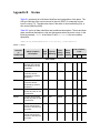
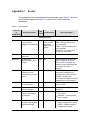
Appendix A TL1 Command by Function
Appendix B Alarms
Appendix C Events
Index
4
TimeProvider TL1 Reference Guide
097-58001-01 Revision G – April 2008
Table of Contents
Tables
1-1
1-2
1-3
1-4
1-5
1-6
Normal Response Fields . . . . . . . . . . . . . . . . . . . . . . . . . . . . . . . . . . . . . . . . . . . . 17
Error Response Fields . . . . . . . . . . . . . . . . . . . . . . . . . . . . . . . . . . . . . . . . . . . . . . 18
Error Codes Returned in Error Responses. . . . . . . . . . . . . . . . . . . . . . . . . . . . . . . 18
In-Process Response Fields. . . . . . . . . . . . . . . . . . . . . . . . . . . . . . . . . . . . . . . . . . 20
Autonomous Message Fields . . . . . . . . . . . . . . . . . . . . . . . . . . . . . . . . . . . . . . . . . 21
TimeProvider TL1 Command Types and Access Levels . . . . . . . . . . . . . . . . . . . . 24
2-1
2-2
2-3
2-4
2-5
2-6
2-7
2-8
2-9
2-10
2-11
2-12
2-13
2-14
2-15
2-16
2-17
2-18
2-19
2-20
2-21
2-22
2-23
2-24
2-25
2-26
2-27
2-28
2-29
2-30
2-31
2-32
2-33
2-34
2-35
2-36
TL1 Syntax Conventions . . . . . . . . . . . . . . . . . . . . . . . . . . . . . . . . . . . . . . . . . . . . 28
ED-DAT – Keywords and Values for <aid>=SYS . . . . . . . . . . . . . . . . . . . . . . . . . . 44
ED-CMD-SECU – Keyword and Values for <cid>=text string. . . . . . . . . . . . . . . . . 45
ED-DAT – Keywords and Values for <aid>=SYS . . . . . . . . . . . . . . . . . . . . . . . . . . 47
ED-EQPT – Keywords and Values . . . . . . . . . . . . . . . . . . . . . . . . . . . . . . . . . . . . . 49
ED-SYNC – Keywords and Values. . . . . . . . . . . . . . . . . . . . . . . . . . . . . . . . . . . . . 59
ED-USER-SECU – Keyword and Values for <uid>=text string . . . . . . . . . . . . . . . 65
INIT-SYS Keywords . . . . . . . . . . . . . . . . . . . . . . . . . . . . . . . . . . . . . . . . . . . . . . . . 73
RTRV-ALM Output Fields . . . . . . . . . . . . . . . . . . . . . . . . . . . . . . . . . . . . . . . . . . . . 81
RTRV-ATTR – Keywords and Values for all <aids> . . . . . . . . . . . . . . . . . . . . . . . . 83
RTRV-ATTR Output Fields . . . . . . . . . . . . . . . . . . . . . . . . . . . . . . . . . . . . . . . . . . . 84
RTRV-BESTIME-STAT Output Fields. . . . . . . . . . . . . . . . . . . . . . . . . . . . . . . . . . . 85
Retrieve Built-In Self Test Output Fields. . . . . . . . . . . . . . . . . . . . . . . . . . . . . . . . . 88
RTRV-CMD-SECU Output Fields . . . . . . . . . . . . . . . . . . . . . . . . . . . . . . . . . . . . . . 92
RTRV-COND Output Fields . . . . . . . . . . . . . . . . . . . . . . . . . . . . . . . . . . . . . . . . . . 96
RTRV-CRAFT Output Fields . . . . . . . . . . . . . . . . . . . . . . . . . . . . . . . . . . . . . . . . 100
RTRV-DAT Output Fields . . . . . . . . . . . . . . . . . . . . . . . . . . . . . . . . . . . . . . . . . . . 107
RTRV-EQPT Output Field. . . . . . . . . . . . . . . . . . . . . . . . . . . . . . . . . . . . . . . . . . . 110
RTRV-GPS-STAT Output Fields . . . . . . . . . . . . . . . . . . . . . . . . . . . . . . . . . . . . . . 111
RTRV-INV Output Fields . . . . . . . . . . . . . . . . . . . . . . . . . . . . . . . . . . . . . . . . . . . 113
RTRV-LED Output Fields . . . . . . . . . . . . . . . . . . . . . . . . . . . . . . . . . . . . . . . . . . . 115
RTRV-LOG – Keywords for all <aids> . . . . . . . . . . . . . . . . . . . . . . . . . . . . . . . . . 118
RTRV-LOG Event Output Fields. . . . . . . . . . . . . . . . . . . . . . . . . . . . . . . . . . . . . . 118
RTRV-LOG Alarm Output Fields . . . . . . . . . . . . . . . . . . . . . . . . . . . . . . . . . . . . . 119
RTRV-NTP-PEER Output Fields . . . . . . . . . . . . . . . . . . . . . . . . . . . . . . . . . . . . . 122
RTRV-PM – Keywords for all <aids> . . . . . . . . . . . . . . . . . . . . . . . . . . . . . . . . . . 124
RTRV-PM Keyword Modifier Fields . . . . . . . . . . . . . . . . . . . . . . . . . . . . . . . . . . . 124
RTRV-PM Output Fields . . . . . . . . . . . . . . . . . . . . . . . . . . . . . . . . . . . . . . . . . . . . 125
RTRV-SYNC Output Field . . . . . . . . . . . . . . . . . . . . . . . . . . . . . . . . . . . . . . . . . . 132
RTRV-TH – Output Fields. . . . . . . . . . . . . . . . . . . . . . . . . . . . . . . . . . . . . . . . . . . 135
RTRV-USER-SECU Output Fields . . . . . . . . . . . . . . . . . . . . . . . . . . . . . . . . . . . . 137
SET-ATTR – Keywords and Values for all <aids> . . . . . . . . . . . . . . . . . . . . . . . . 141
SET-SID – Keyword and Value. . . . . . . . . . . . . . . . . . . . . . . . . . . . . . . . . . . . . . . 142
SET-SYS-MODE – Keyword and Values . . . . . . . . . . . . . . . . . . . . . . . . . . . . . . . 143
SET-TH – Keywords and Values for all <aids>. . . . . . . . . . . . . . . . . . . . . . . . . . . 145
Mask Table . . . . . . . . . . . . . . . . . . . . . . . . . . . . . . . . . . . . . . . . . . . . . . . . . . . . . . 146
A-1
A-2
A-3
Security and Administrative Commands. . . . . . . . . . . . . . . . . . . . . . . . . . . . . . . . 147
System Commands . . . . . . . . . . . . . . . . . . . . . . . . . . . . . . . . . . . . . . . . . . . . . . . 148
Performance Monitoring Commands . . . . . . . . . . . . . . . . . . . . . . . . . . . . . . . . . . 149
097-58001-01 Revision G – April 2008
TimeProvider TL1 Reference Guide
5
Table of Contents
B-1
B-2
Alarms . . . . . . . . . . . . . . . . . . . . . . . . . . . . . . . . . . . . . . . . . . . . . . . . . . . . . . . . . 151
Alarm Code Condition Descriptions . . . . . . . . . . . . . . . . . . . . . . . . . . . . . . . . . . . 161
C-1
C-2
Event Identifiers . . . . . . . . . . . . . . . . . . . . . . . . . . . . . . . . . . . . . . . . . . . . . . . . . . 165
Event Code Condition Descriptions . . . . . . . . . . . . . . . . . . . . . . . . . . . . . . . . . . . 177
6
TimeProvider TL1 Reference Guide
097-58001-01 Revision G – April 2008
How to Use This Guide
This section describes the format, layout, and purpose of this guide.
In This Preface
Purpose of This Guide
Who Should Read This Guide
Structure of This Guide
Conventions Used in This Guide
Warnings, Cautions, Recommendations, and Notes
Related Documents and Information
Where to Find Answers to Product and Document Questions
What’s New In This Guide
097-58001-01 Revision G – April 2008
TimeProvider TL1 Reference Guide
7
How to Use This Guide
Purpose of This Guide
Purpose of This Guide
The TimeProvider TL1 Reference Guide provides information on TL1 command
conventions and parameters. It covers command types, formats, and responses. It
provides an explanation of the command function and a description of each
command parameter, value, and variable when applicable. It also describes
keywords used during provisioning and provides a troubleshooting guide.
Who Should Read This Guide
This guide is a command reference intended for engineers and telecommunications
professionals who provision and manage the TimeProvider Node Clock. Chapter 1,
TL1 Overview is for those who need a basic understanding of the Transaction
Language 1 (TL1) protocol and how it is implemented in the TimeProvider.
Chapter 2, TL1 Command Syntax and Description describes TimeProvider TL1
commands in detail (commands are listed in alphabetical order). Appendix A, TL1
Command by Function is a list of commands grouped by task (security and
administration, system performance, and performance monitoring). Appendix B,
Alarms and Appendix C, Events provide a list of alarms and events along with a
description of the cause of the event.
Structure of This Guide
This guide contains the following sections:
Chapter, Title
8
Description
Chapter 1, TL1 Overview
Provides a basic overview of the Transaction Language 1 (TL1)
used by the TimeProvider.
Chapter 2, TL1 Command
Syntax and Description
Describes each of the TimeProvider’s TL1 commands in detail.
Appendix A, TL1 Command
by Function
Provides task-oriented lists of security and administrative
commands, system commands, and performance monitoring
commands.
Appendix B, Alarms
Provides a list of all alarms and a description of their cause.
Appendix C, Events
Provides a list of all events and a description of their cause.
Index
Provides references to individual topics within this guide.
TimeProvider TL1 Reference Guide
097-58001-01 Revision G – April 2008
How to Use This Guide
Conventions Used in This Guide
Conventions Used in This Guide
This guide uses the following conventions:
Acronyms and Abbreviations – Terms are spelled out the first time they appear
in text. Thereafter, only the acronym or abbreviation is used.
Revision Control – The title page lists the printing date and versions of the
product this guide describes.
Typographical Conventions – This guide uses the typographical conventions
described in the table below.
When text appears
this way...
... it means:
TimeProvider TL1 Reference
Guide
The title of a document.
CRITICAL
PORT-A
J1
An operating mode, alarm state, status, or chassis label.
Select File, Open...
Click the Open option on the File menu.
Press Enter.
Press Print Scrn.
A named keyboard key.
The key name is shown as it appears on the keyboard.
An explanation of the key’s acronym or function
immediately follows the first reference to the key, if
required.
TimeProvider
Username:
Text in a source file or a system prompt or other text that
appears on a screen.
ENGINE TDATA
STATUS
A command you enter at a system prompt or text you
enter in response to a program prompt. You must enter
commands for case-sensitive operating systems exactly
as shown.
A re-timing application
A word or term being emphasized.
Symmetricom does not
recommend...
A word or term given special emphasis.
Structure of This Guide, on
page 8
The blue text, when viewed in a pdf file, indicates a
hyperlink to the indicated text.
097-58001-01 Revision G – April 2008
TimeProvider TL1 Reference Guide
9
How to Use This Guide
Warnings, Cautions, Recommendations, and Notes
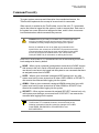
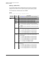
Warnings, Cautions, Recommendations, and Notes
Warnings, Cautions, Recommendations, and Notes attract attention to essential or
critical information in this guide. The types of information included in each are
explained in the following examples.
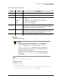
Warning: To avoid serious personal injury or death, do not
disregard warnings. All warnings use this symbol. Warnings are
installation, operation, or maintenance procedures, practices, or
statements, that if not strictly observed, may result in serious
personal injury or even death.
Caution: To avoid personal injury, do not disregard cautions. All
cautions use this symbol. Cautions are installation, operation, or
maintenance procedures, practices, conditions, or statements, that
if not strictly observed, may result in damage to, or destruction of,
the equipment. Cautions are also used to indicate a long-term
health hazard.
ESD Caution: To avoid personal injury and electrostatic discharge
(ESD) damage to equipment, do not disregard ESD cautions. All
ESD cautions use this symbol. ESD cautions are installation,
operation, or maintenance procedures, practices, conditions, or
statements that if not strictly observed, may result in possible
personal injury, electrostatic discharge damage to, or destruction of,
static sensitive components of the equipment.
Electrical Shock Caution: To avoid electrical shock and possible
personal injury, do not disregard electrical shock cautions. All
electrical shock cautions use this symbol. Electrical shock cautions
are practices, procedures, or statements, that if not strictly
observed, may result in possible personal injury, electrical shock
damage to, or destruction of components of the equipment.
Recommendation: All recommendations use this symbol.
Recommendations indicate manufacturer-tested methods or known
functionality. Recommendations contain installation, operation, or
maintenance procedures, practices, conditions, or statements, that
provide important information for optimum performance results.
Note: All notes use this symbol. Notes contain installation,
operation, or maintenance procedures, practices, conditions, or
statements, that alert you to important information, which may
make your task easier or increase your understanding.
10
TimeProvider TL1 Reference Guide
097-58001-01 Revision G – April 2008
How to Use This Guide
Related Documents and Information
Related Documents and Information
Other helpful documents are listed below. See your Symmetricom representative or
sales office for a complete list of available documentation.
TimeProvider Node Clock User’s Guide, part number 097-58001-02
Software Release Notice, part number 097-58001-24
TimePictra management software – See the User’s manual provided on the
system CD
SynCraft management software – Help files within the application
Note: Symmetricom offers a number of applicable training courses
designed to enhance product usability. Contact your local
representative or sales office for a complete list of courses and
outlines.
Where to Find Answers to Product and Document
Questions
For additional information about the products described in this guide, please contact
your Symmetricom representative or your local sales office. You can also contact us
on the web at www.symmetricom.com.
What’s New In This Guide
No Revision F of this guide has been issued. Revision G of this guide contains the
following new information.
Added a description of the GR-833 response format in Autonomous Messages,
on page 20.
Changed the default value of INACTTIME to 1800, in Table 2-5.
Added the GPSCLRDEL and GPSFLTDEL keywords to Table 2-6.
Added new keywords to Edit User Security (ED-USER-SECU), on page 65.
Added TPIU and group parameters to Remove Equipment (RMV-EQPT), on
page 77.
Added the GPSCLRDEL and GPSFLTDEL parameters to the SYS: response in
Retrieve Craft Data (RTRV-CRAFT), on page 99.
Added the scavail parameter to the IOCx response in Retrieve Craft Data
(RTRV-CRAFT), on page 99.
097-58001-01 Revision G – April 2008
TimeProvider TL1 Reference Guide
11
How to Use This Guide
What’s New In This Guide
12
Added the EVTFORMAT keyword to Retrieve Craft Data (RTRV-CRAFT), Edit
Equipment (ED-EQPT), Table 2-5, Table 2-16, Table C-1, Table C-2.
Added the PLNA error code to Retrieve Header (RTRV-HDR), on page 112.
Changed the KEYID parameter values to 0 to 65535 in ED-EQPT for NTP
Parameters and in Table 2-16.
Changed the Retrieve Alarm Condition (RTRV-ALM) command description to
include the -ALL, -EQPT, and -T1 modifiers.
Changed the Retrieve Condition (RTRV-COND) command description to include
the -ALL modifier.
Added the GR-833 response format to the Retrieve Alarm Condition
(RTRV-ALM) and Enter User Security (ENT-USER-SECU) commands.
Removed the TPIU keyword from Remove Equipment (RMV-EQPT), on page 77.
Changed the Error Delay Default to GPSFLTDEL for ANTCOM, GPSPOS,
GPSPWR, GPSSYS, and GPSTRK in Table B-1.
Changed the GPSPOS default alarm level to MN in Table B-1.
Added SNMP Event conditions to Table C-2.
Added AUTHPASS, AUTHPRIV, and PRIVPASS events to IMC in Table C-2.
Added GPSCLRDEL and GPSFLTDEL to Table C-2.
TimeProvider TL1 Reference Guide
097-58001-01 Revision G – April 2008
Chapter 1 TL1 Overview
This chapter provides a basic overview of the Transaction Language 1 (TL1) used
by the TimeProvider.
In This Chapter
Overview
TL1 Command Structure
Responses
Autonomous Messages
Command Security
097-58001-01 Revision G – April 2008
TimeProvider TL1 Reference Guide
13
Chapter 1 TL1 Overview
Overview
Overview
Transaction Language 1 (TL1) is the most widely used management language in
the telecommunications industry. TL1 provides a standardized set of
vendor-independent, ASCII-based instructions that can be used to manage network
elements (NEs) and their resources. The TimeProvider uses TL1 as its
human-to-machine command line interface (CLI).
Note: For a complete description of the TL1 syntax, refer to Telcordia
(Bellcore) General Requirements GR-831 and GR-833.
The remainder of this chapter explains the TL1 command language and how it
applies to the TimeProvider.
TL1 Command Structure
The TL1 commands used in the TimeProvider consist of the following three main
parts, or blocks:
The Command Code Block
The Staging Block
The Payload Block
These three main blocks are separated by a colon ( : ) block separator character
and the command is terminated by a semicolon ( ; ) terminating character. The
semicolon indicates that the command statement is completed and the command is
then executed.
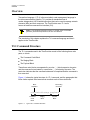
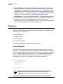
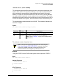
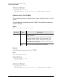
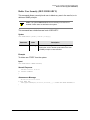
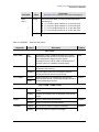
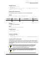
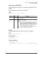
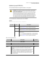
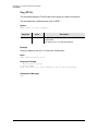
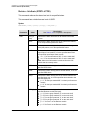
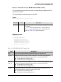
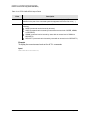
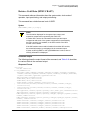
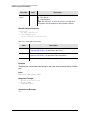
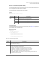
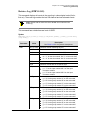
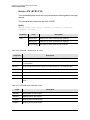
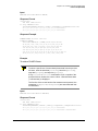
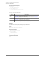
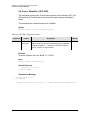
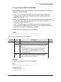
Figure 1-1 shows the typical structure of a TL1 command, and the paragraphs that
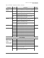
follow further explain the elements that constitute each of the main blocks.
Block
Separator
Terminating
Character
cid:tid:aid:ctag::payload;
Command
Code
Block
Figure 1-1.
14
Staging
Block
Payload
Block
Typical TL1 Command Structure
TimeProvider TL1 Reference Guide
097-58001-01 Revision G – April 2008
Chapter 1 TL1 Overview
TL1 Command Structure
Command Code Block
The Command Code Block uniquely identifies the command and identifies the
action to be taken. It consists of a verb and one or more modifiers, separated by the
dash character ( - ).
ED-DAT, for instance, is the command code block used in the TimeProvider’s “Edit
Date” TL1 command. ED is the verb and DAT is the modifier indicating that the
command will edit a date object.
Staging Block
The Staging Block is comprised of the following blocks, each separated by the block
separator character.
The Target Identifier (tid) – The tid identifies the specific TimeProvider unit to
which the command applies. The position of the tid is mandatory within the
command string, but it is usually optional sense its value can be null. If it is used
in the command, it must match the Source Identifier (sid) that is set within the unit
or the unit will not respond to the command. If the command is not directly sent to
the unit, as when the command is routed to the unit via a Gateway NE (called
indirect routing), a non-null tid is required.
The Access Identifier (aid) – The aid uniquely identifies the entity within the
associated target unit. In the TL1 syntax descriptions provided in Chapter 2 of
this manual, the <aid> syntax tag is used specifically to denote modules, inputs,
outputs, or ports. Other more specific syntax tags are used to denote types of
entities, such as <uid> a user identifier, or <cid> a command identifier. The
position of the aid block within the command string always occurs between the
second and third block separator character.
The Correlation Tag (ctag) – The ctag is used to correlate commands and
responses. It can be any alphanumeric string up to six characters in length. In the
TimeProvider, use of the ctag is not mandatory, but is strongly recommended. If
the value for the ctag is null in the command string, the unit returns a zero ( 0 ) as
the ctag in responses.
The General Block – In the TimeProvider the General Block is not used so its
value should always be null. If the General Block is the last block in the command
syntax, it, and the remaining block separator characters can be omitted from the
command string.
Payload Block
The Payload Block contains the parameters associated with the command’s
operation. In the TimeProvider’s command syntax, the Payload Block can take on
either of the following two forms, depending on the command:
097-58001-01 Revision G – April 2008
TimeProvider TL1 Reference Guide
15
Chapter 1 TL1 Overview
Responses
Position-Defined – In a position-defined payload block, the parameters that
make up the block are implied by their position within the block. The individual
parameters are separated by the comma character ( , ). If the value of a given
parameter is null, its position within the block still must be maintained by using
adjacent commas ( ,, ). Refer to Copy Memory (CPY-MEM), on page 39 for an
example of a command that uses a position-defined payload block.
Name-Defined – In a name-defined payload block, the parameters that make up
the block take on the form <keyword>=<value>. The <keyword> identifies the
parameter, and <value> is that parameter’s value. Keywords are not
case-sensitive. Refer to Edit Equipment (ED-EQPT), on page 48 for an example
of a command that uses a name-defined payload block.
Responses
When the TimeProvider receives and processes a command, it returns one of the
following types of responses:
Normal Response
Large Response
Error Response
In-Process Response
The following paragraphs explain these response types.
Normal Response
The TimeProvider sends a Normal response when it receives and can properly
process a TL1 command. The response is always in uppercase letters. The format
of a Normal response is as follows. The M indicates that the message is a response
to a TL1 command. When the response is COMPLD and the command requires a
response message, then one or more lines are returned and the response is
terminated by a semicolon. The syntax for the command response is:
<cr><lf><lf>
sid date time<cr><lf>
M ctag COMPLD<cr><lf>
textblk<cr><lf>
textblk<cr><lf>
.
.
LG_textblk<cr><lf>
;
Note: The textblk and LG_textblk fields are only returned with the
Normal response when the command requires such a message be
returned.
16
TimeProvider TL1 Reference Guide
097-58001-01 Revision G – April 2008
Chapter 1 TL1 Overview
Responses
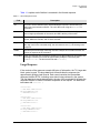
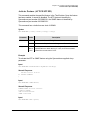
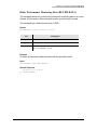
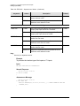
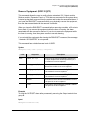
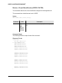
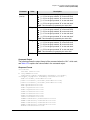
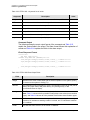
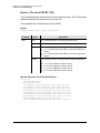
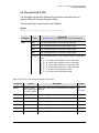
Table 1-1 explains each field that is contained in the Normal response.
Table 1-1. Normal Response Fields
Field
Description
sid
The unit’s Source Identifier (SID), which identifies the specific TimeProvider unit
within the synchronization network. The unit’s SID is set using the SET-SID TL1
command.
date
The date of the response, in the format YY-MM-DD, where YY is the 2-digit year, MM
is the 2-digit representation of the month, and DD is the day of the month.
time
The time of the response, in the format HH:MM:SS, where HH is the hour in 24-hour
format, MM is the minutes, and SS is the seconds.
ctag
The correlation tag that was sent as part of the TL1 command string. If the value for
the ctag is null in the command string, the unit returns a zero ( 0 ) as the ctag in the
response.
textblk
A double-quoted message containing less than 4 kBytes of information that the unit
returns in response to the command.
LG_textblk
If the unit responds with a message containing more than 4 kBytes of information, the
message is divided into records of approximately 4 kBytes, each ending with
COMPLD<cr><lf>. The last record ends with <cr><lf>;.
Large Response
If the contents of the response exceeds 4K bytes of information, the TL1 large data
block syntax is used. The large data block format divides the response into
approximately 4Kbyte-sized records. Each record contains the intermediate
response identifier RTRV, indicating more data is being retrieved by the system.
The final data block size is determined by the size of the remainder of the data; the
response identifier COIMPLD indicates completion of the request. The data block
terminates with <cr><lf> ;.
<cr><lf><lf>
^^^sid^date^time<cr><lf>
IP^ctag^RTRV<cr><lf>
^^^textblk<cr><lf> *
>
<cr><lf><lf>
^^^sid^date^time<cr><lf>
IP^ctag^RTRV<cr><lf>
^^^textblk<cr><lf> *
>
<cr><lf><lf>
^^^sid^date^time<cr><lf>
M^^ctag^COMPLD<cr><lf>
^^^textblk<cr><lf> *
;
097-58001-01 Revision G – April 2008
TimeProvider TL1 Reference Guide
17
Chapter 1 TL1 Overview
Responses
Error Response
The TimeProvider sends an Error response when a command is mis-typed, an
invalid command is issued, or some other operator error is performed. The format of
an Error response is as follows. Note that M and DENY identify the response as an
Error response:
<cr><lf><lf>
sid date time<cr><lf>
M ctag DENY<cr><lf>
errcde<cr><lf>
;
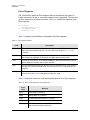
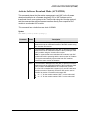
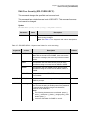
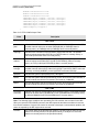
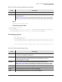
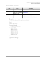
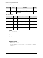
Table 1-2 explains each field that is contained in the Error response.
Table 1-2. Error Response Fields
Field
Description
sid
The unit’s Source Identifier (SID), which identifies the specific TimeProvider unit
within the synchronization network. The unit’s SID is set using the SET-SID TL1
command.
date
The date of the response, in the format YY-MM-DD, where YY is the 2-digit year, MM
is the 2-digit representation of the month, and DD is the day of the month.
time
The time of the response, in the format HH:MM:SS, where HH is the hour in 24-hour
format, MM is the minutes, and SS is the seconds.
ctag
The correlation tag that was sent as part of the TL1 command string. If the value for
the ctag is null in the command string, the unit returns a zero ( 0 ) as the ctag in the
response.
errcde
The error code, which identifies the condition that caused the Error response to be
returned. See Table 1-3 for a description of each error code.
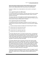
Table 1-3 describes each error code that might be returned in an Error response.
Table 1-3. Error Codes Returned in Error Responses
Error
Code
18
Meaning
IBEX
Extra Block in Command
IBMS
Missing Block in Command
ICNV
Command Not Valid (invalid TL1 syntax)
IIAC
Invalid AID Code
IICM
Invalid Command (invalid command or command
with insufficient security clearance)
TimeProvider TL1 Reference Guide
097-58001-01 Revision G – April 2008
Chapter 1 TL1 Overview
Responses
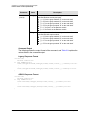
Table 1-3. Error Codes Returned in Error Responses (Continued)
Error
Code
Meaning
IICT
Invalid CTAG
IITA
Invalid Target Identifier
IPEX
Extra Parameter
IPMS
Parameter Missing
IPNV
Parameter Not Valid
ISCH
Invalid Character, syntax
ISPC
Invalid Punctuation, syntax
PLNA
Privilege, Login Not Active
SDBE
Database Error
SDNR
Data Not Ready
SRAC
Requested Access Configuration Not Valid
SROF
Requested Operation Failed
SROU
Requested Operation Unnecessary
SWFA
Working Unit Failed
In-Process Response
If the TimeProvider cannot send a Normal response, a Large response, or an Error
response within two seconds of receipt of a command, it sends an In-Process
response. The format of an In-Process response is as follows. Note that IP
identifies the response as an In-Process response:
TL1-Command;IP^ctag<cr><lf>
<
<cr><lf><lf>
^^^sid^date^time<cr><lf>
M^^ctag^COMPLD<cr><lf>
^^^textblk<cr><lf> *
;
where '*' indicates zero or more of the preceding element
097-58001-01 Revision G – April 2008
TimeProvider TL1 Reference Guide
19
Chapter 1 TL1 Overview
Autonomous Messages
When the TimeProvider finishes processing the original command, the In-Process
response is followed with either a Normal or Error response, as is appropriate. Table
1-4 provides a description of each field contained in the In-Process response.
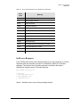
Table 1-4. In-Process Response Fields
Field
Description
sid
The unit’s Source Identifier (SID), which identifies the specific TimeProvider unit
within the synchronization network. The unit’s SID is set using the SET-SID TL1
command.
date
The date of the response, in the format YY-MM-DD, where YY is the 2-digit year, MM
is the 2-digit representation of the month, and DD is the day of the month.
time
The time of the response, in the format HH:MM:SS, where HH is the hour in 24-hour
format, MM is the minutes, and SS is the seconds.
ctag
The correlation tag that was sent as part of the TL1 command string. If the value for
the ctag is null in the command string, the unit returns a zero ( 0 ) as the ctag in the
response.
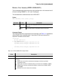
Autonomous Messages
In addition to the TL1 responses described above, the TimeProvider might return
Autonomous Messages to report alarms, configuration changes, or condition
changes. Frequently, an Autonomous Message is returned at approximately the
same time as the TL1 response that is associated with a command, because the
command happens to cause a change in the unit’s state. Autonomous Messages
are not directly correlated with commands and they do not contain correlation tags
(ctags). They should, however, have an <atag>, which increments by one (from 1 to
999999) for each autonomous event.
Note: By default, Autonomous Messages are displayed in the user’s
session. The display of Autonomous Messages can be enabled or
disabled using the ED-EQPT TL1 command with the AOMERGE
keyword.
Autonomous Messages can be generated by the unit at any time, whether to report
that a user-initiated change has occurred to some setting within the unit, to report
that an active alarm condition has cleared, etc. The format of an Autonomous
Message is as follows. Note that REPT identifies the response as an Autonomous
Message: EVT for an event and ALM for an alarm.
20
TimeProvider TL1 Reference Guide
097-58001-01 Revision G – April 2008
Chapter 1 TL1 Overview
Autonomous Messages
TimeProvider release 3.2 adds a second response format that meets GR-833. A
new keyword, EVTFORMAT, allows you to select between the TimeProvider’s
legacy format and the GR-833 format (see Edit Equipment (ED-EQPT), on page 48
for details). You can only run the legacy format when you are managing the
TimeProvider with TimeCraft 1.2 or earlier versions or TimePictra 3.7 or earlier
versions. To use the GR833 format, you must have TimeCraft 1.3 or later versions
or TimePictra 3.8 or later versions.
Legacy Event Response Format:
<cr><lf><lf>
sid date time<cr><lf>
alrmcde atag REPT EVT {EQPT | T1}<cr><lf>
”aid,aidtype:condtype,condeff,ocrdat,ocrtim,,,,:condscr”<cr lf>
;
GR-833 Event Response Format:
<cr><lf><lf>
sid date time<cr><lf>
alrmcde atag REPT EVT [AIDTYPE]<cr><lf>
”aid:condtype,condeff,ocrdat,ocrtim,,,,:condscr”<cr lf>
;
Alarm Response Format:
<cr><lf><lf>
sid date time<cr><lf>
alrmcde atag REPT ALM [AIDTYPE]<cr><lf>
”aid,aidtype:ntfcncde,condtype,srveff,ocrdat,ocrtim,,:condscr”<cr lf>
;
Table 1-5 explains each field that is contained in an Autonomous Message.
Table 1-5. Autonomous Message Fields
Field
Description
sid
The unit’s Source Identifier (SID), which identifies the specific TimeProvider unit within
the synchronization network. The unit’s SID is set using the SET-SID TL1 command.
date
The date of the message, in the format YY-MM-DD, where YY is the 2-digit year, MM is
the 2-digit representation of the month, and DD is the day of the month.
time
The time of the message, in the format HH:MM:SS, where HH is the hour in 24-hour
format, MM is the minutes, and SS is the seconds.
almcde
The alarm code, which can be one of the following:
*C - The event being reported is a Critical alarm
** - The event being reported is a Major alarm
* - The event being reported is a Minor alarm
A - The event being reported is a Non-alarm Event
atag
The Autonomous Message tag, which is a number up to six digits long that increments
by one each time an event is generated. It wraps back to 1 after reaching 999999.
097-58001-01 Revision G – April 2008
TimeProvider TL1 Reference Guide
21
Chapter 1 TL1 Overview
Autonomous Messages
Table 1-5. Autonomous Message Fields (Continued)
Field
Description
reptype
The type of report. It can be either EVT (the event is a non-alarm event), or ALM (the
event is an alarm event).
aid
The access identifier, which denotes the system component that the reported alarm or
event applies to.
aidtype
The aid type. It can be EQPT (the aid is associated with the internal operation of the
system) or T1 (the aid is external to the system or facility; for example, an input or output).
Note: The aidtype that follows the reptype in the Autonomous Message is included only
if the reptype is ALM.
ntfcncde
The notification code for the alarm or event. The notification code can be CR (a critical
alarm), MJ (a major alarm), MN (a minor alarm), CL (a cleared alarm), or NA (a non-alarm
event).
condtype
The condition type, which is the TL1 code that is associated with the alarm or event.
Table C-2 shows all of the possible TimeProvider event condition types, and Table B-2
shows all of the possible TimeProvider alarm condition types.
condeff
This defines an event’s effect on the system: CL indicates clearing of a standing condition,
SC indicates a standing condition is raised, and TC indicates a transition of a condition.
Note: All events listed in Table C-2 set CONDEFF to TC. If alarms listed in Table B-2 are
provisioned as Not Alarmed (NA), CONDEFF is set to SC when the alarm becomes
active and CL when the alarm becomes inactive.
srveff
Whether the alarm or event is service affecting (SA) or non-service affecting (NSA).
ocrdat
The date the alarm or event occurred, in the format YY-MM-DD.
ocrtim
The time that the alarm or event occurred, in the format HH:MM:SS.
condscr
The condition string, which is a description of the alarm or event. It is a quoted text
string, preceded with the “\” escape character. Table C-2 shows all of the possible
TimeProvider event condition strings, and Table B-2 shows all of the possible
TimeProvider alarm and clearing alarm condition strings.
Table B-2 shows all of the possible alarm condition types (condtypes) and alarm
condition strings (condscrs) that might be returned by the TimeProvider in an
Autonomous Message.
Table C-2 shows all of the possible event condition types (condtypes) and event
condition strings (condscrs) that might be returned by the TimeProvider in an
Autonomous Message.
22
TimeProvider TL1 Reference Guide
097-58001-01 Revision G – April 2008
Chapter 1 TL1 Overview
Command Security
Command Security
To protect system resources and information from unauthorized access, the
TimeProvider implements the concept of access levels for commands.
When security is enabled on the TimeProvider, most of the unit’s TL1 commands
require that users be logged into the system in order to access them. Each user in
the system has a user access level assigned to them, and it is their user access
level that determines which commands they can use.
Caution: Security is initially not enabled on the TimeProvider. With
security not enabled, anyone can execute any of the unit’s TL1
commands, severely compromising the integrity of the system.
Security is activated as soon as an initial user is entered into the
system with a user access level of SECURITY. Symmetricom strongly
recommends that an initial Security-level user be defined in the system
as soon as the system is installed. Refer to the TimeProvider User
Guide (097-58001-02) for information on defining the first user.
Each of the TimeProvider’s TL1 commands have one of the following four access
levels assigned to them by default:
NONE – When a given command is assigned an access level of NONE, anyone
with access to the unit’s Serial or Ethernet ports can execute the command. A
user doesn’t even have to be logged into the system to use commands that have
an assigned access level of NONE.
USER – When a given command is assigned USER access level, any valid
system user having a user access level of either USER, ADMIN, or SECURITY
can execute the command after logging into the system.
ADMIN – When a given command is assigned ADMIN access level, any valid
system user having a user access level of either ADMIN or SECURITY can
execute the command after logging into the system.
SECURITY – When a given command is assigned SECURITY access level, only
valid system users having a user access level of SECURITY can execute the
command after logging into the system.
Note: The factory default access level can be changed for most of the
TimeProvider TL1 commands, however, the access level for the
following commands is fixed and cannot be changed: ACT-USER,
CANC-USER, ED-CMD-SECU, ED-USER-SECU, and
ENT-USER-SECU.
097-58001-01 Revision G – April 2008
TimeProvider TL1 Reference Guide
23
Chapter 1 TL1 Overview
Command Security
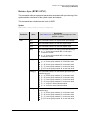
Table 1-6 lists each of the TimeProvider’s TL1 commands in alphabetical order. The
command type and default (factory set) access level is included in Table 1-6 for
each command.
Table 1-6. TimeProvider TL1 Command Types and Access Levels
Command Name
24
Command Type
Factory-Set
Access Level
ACT-FEATURE
Administrative
ADMIN
ACT-SWDL
Administrative
ADMIN
ACT-USER
Session
NONE
CANC-USER
Session
USER
CPY-MEM
System
ADMIN
DLT-PM-DATA
Administrative
USER
DLT-SECU
Administrative
SECURITY
DLT-USER-SECU
Administrative
SECURITY
ED-CKTID
System
USER
ED-CMD-SECU
Administrative
ADMIN
ED-DAT
System
ADMIN
ED-EQPT
System
ADMIN
ED-PID
Administrative
USER
ED-SYNC
System
ADMIN
ED-USER-SECU
Administrative
SECURITY
ENT-PID
Administrative
SECURITY
ENT-USER-SECU
Administrative
SECURITY
INIT-LOG
System
ADMIN
INIT-SYS
System
ADMIN
OPR-ACO-ALL
System
USER
PING
Session
USER
RMV-EQPT
System
USER
RTRV-ALM
System
USER
RTRV-ATTR
System
USER
RTRV-BESTIME-STAT
Administrative
USER
RTRV-BIST
System
USER
RTRV-CKTID
System
USER
RTRV-CMD-SECU
Administrative
ADMIN
TimeProvider TL1 Reference Guide
097-58001-01 Revision G – April 2008
Chapter 1 TL1 Overview
Command Security
Table 1-6. TimeProvider TL1 Command Types and Access Levels (Continued)
Command Name
Command Type
Factory-Set
Access Level
RTRV-COND
System
USER
RTRV-CRAFT
System
USER
RTRV-DAT
System
USER
RTRV-EQPT
System
USER
RTRV-GPS-STAT
System
USER
RTRV-HDR
System
NONE
RTRV-INV
System
USER
RTRV-LED
System
USER
RTRV-LOG
Administrative
USER
RTRV-NETYPE
System
NONE
RTRV-NTP-PEER
System
USER
RTRV-PM
System
USER
RTRV-SYNC
System
USER
RTRV-SYS-MODE
System
USER
RTRV-TH
System
USER
RTRV-USER
Session
USER
RTRV-USER-SECU
Administrative
SECURITY
SET-ATTR
System
ADMIN
SET-SID
System
ADMIN
SET-SYS-MODE
System
ADMIN
SET-TH
System
ADMIN
097-58001-01 Revision G – April 2008
TimeProvider TL1 Reference Guide
25
Chapter 1 TL1 Overview
Command Security
26
TimeProvider TL1 Reference Guide
097-58001-01 Revision G – April 2008
Chapter 2 TL1 Command Syntax and Description
This chapter describes each of the TimeProvider’s TL1 commands in detail.
In This Chapter
TL1 Syntax Conventions
Command Descriptions
097-58001-01 Revision G – April 2008
TimeProvider TL1 Reference Guide
27
Chapter 2 TL1 Command Syntax and Description
TL1 Syntax Conventions
Table 2-1 describes the syntax used for commands and responses in this manual.
Table 2-1. TL1 Syntax Conventions
Symbol
Description
<cr>
Carriage return character (ASCII 0x0D).
<lf>
Line-feed character (ASCII 0x0A).
[ ... ]
Indicates the command parameter or data is optional.
< ... >
Indicates a variable. The variable’s value is actually sent in the command
or returned in the response.
( ... )
Indicates numeric data that can be either positive or negative.
In addition, the following general rules apply to the TL1 syntax and command entry:
Adjacent colons indicate unused fields. If an unused field is the last parameter in
the command string, for example the General Block or Parameter Block is the
last block and is unused, you can omit the colons and simply enter the semicolon
terminating character to execute the command.
The TimeProvider ignores extra spaces in the TL1 command line.
TL1 commands are not case sensitive unless specified as such.
Command Descriptions
The TL1 commands that are included in the TimeProvider’s command set comprise
the remainder of this chapter. An entry is included for each command, and the
entries are organized in alphabetical order by verb-modifier command code. Each
command entry is comprised of the following parts:
28
A descriptive title for the command entry, followed by the command’s
verb-modifier command code enclosed in parentheses.
A brief description of the command, and the command’s default access level.
The command syntax, which is followed by the parameters and keywords that
can be used with the command.
Further explanation follows the parameters, keywords, and values where
necessary.
An example of how to use the command completes each command entry.
TimeProvider TL1 Reference Guide
097-58001-01 Revision G – April 2008
Chapter 2 TL1 Command Syntax and Description
Activate Feature (ACT-FEATURE)
Activate Feature (ACT-FEATURE)
This command enables the specified feature in the TimeProvider. Once the feature
has been enabled, it cannot be disabled. The NTP feature is identified by
Symmetricom part number 920-58000-01; the SNMP feature is identified by
Symmetricom part number 920-58002-01.
This command has a default access level of ADMIN.
Syntax
ACT-FEATURE:[<tid>]:<fid>:[<ctag>]::<key>;
Parameter
<fid>
<key>
Value
Description
NTP
Activates the Network Timing Protocol feature.
SNMP
Activates the Simple Network Management Protocol feature.
ASCII
data or
<null>
The key to enable the feature. Contact your Symmetricom
representative to obtain the key. If <null>, then the command
returns the current state of <fid>.
Example
To activate the NTP or SNMP feature using the Symmetricom-supplied <key>
parameter:
Input
ACT-FEATURE::NTP:TP1000::"Symmetricom-Key";
Normal Response
M
;
TP-SSU 05-02-10 13:35:56
TP1000 COMPLD
Input
ACT-FEATURE::SNMP:TP1000;
Normal Response
TIMEPROVIDER 08-03-23 22:54:25
M TP1000 COMPLD
"IMC Serial#=S16026"
"SNMP activated"
Input
ACT-FEATURE::NTP::tp1000;
097-58001-01 Revision G – April 2008
TimeProvider TL1 Reference Guide
29
Chapter 2 TL1 Command Syntax and Description
Activate Feature (ACT-FEATURE)
Normal Response
TIMEPROVIDER 08-03-23 22:56:38
M 0 COMPLD
"IMC Serial#=S16026"
"NTP activated"
Autonomous Message
TP-SSU 05-02-10,13:35:56
A 2528 REPT EVT
"IMC,EQPT:FEATURE,TC,05-02-10,13-35-56,,,,:\"SYSTEM FEATURE HAS BEEN
ACTIVATED, NTP\""
;
30
TimeProvider TL1 Reference Guide
097-58001-01 Revision G – April 2008
Chapter 2 TL1 Command Syntax and Description
Activate Software Download Mode (ACT-SWDL)
Activate Software Download Mode (ACT-SWDL)
This command places the information management card (IMC) in the firmware
download mode prior to a firmware download. IOC or IMC firmware can be
transferred from a users system to the TimeProvider using the Ymodem protocol,
and the command also allows firmware transfers directly from a specified IOC
module to a redundant IOC module.
This command has a default access level of ADMIN.
Syntax
ACT-SWDL:[<tid>]:<aid>:[<ctag>];
Parameter
<aid>
Value
Description
IMC
The Information Management Card (IMC) is placed in firmware
download mode to download firmware to the IMC module using
the Ymodem file receiver.
IOC
The Information Management Card (IMC) is placed in firmware
download mode to download firmware to the Input/Output Card
(IOC) module using the Ymodem file receiver.
Note: In systems that have redundant IOC modules, both IOC
modules should be operating with the same version of firmware.
The system automatically ensures that both IOC modules
receive the same version of firmware.
IOCm
The Information Management Card (IMC) is placed in firmware
download mode to download firmware to the Input/Output Card
(IOC) module and does not use the Ymodem file receiver.
If a new IOC is installed into a system (or if one IOC card has a
previous version of firmware), the active IOC can be used to
transfer its version of firmware to the target IOC.
m = “1” for the module marked “IOC 1" on the main shelf.
m = “2” for the module marked “IOC 2" on the main shelf.
097-58001-01 Revision G – April 2008
TimeProvider TL1 Reference Guide
31
Chapter 2 TL1 Command Syntax and Description
The Firmware Download Process
The Firmware Download Process
Caution: To avoid a possible service call, do not issue any additional
TL1 commands to the TimeProvider, do not remove power from the
TimeProvider, and do not remove an IOC or IMC from the shelf during
the firmware upgrade process (minimum 30 minutes). Doing so could
corrupt the flash memory in a card, disabling the TimeProvider.
When the IMC module is in firmware download mode, most
commands are not executable because all users are logged off the
system; however, commands with an access level of NONE are
executable. Furthermore, if security is not enabled, for example no
users are assigned, any command is executable.
Notes:
Firmware upgrade files are periodically available from Symmetricom.
Contact Symmetricom customer support for information on firmware
upgrades that are available for the TimeProvider.
Refer to the TimeProvider User’s Guide (097-58001-02) for more
complete firmware upgrade information.
The ACT-SWDL command places either the IMC or IOC module (depending on the
specified AID) in the firmware download mode so that firmware upgrades can be
downloaded to the modules. If IOCm (m = 1 or 2) is the specified AID, firmware is
transferred from the specified IOC to the redundant IOC.
Note: Firmware transfer between IOCs is not allowed if the
destination IOC is active.
Firmware download to the IMC or IOC module
When the TimeProvider receives the ACT-SWDL command for either the IMC or
IOC module, it automatically logs all users off of the system and locks the system
against new logins. The system then disconnects TL1 from the connection that sent
the ACT-SWDL command and starts the TimeProvider’s internal Ymodem file
receiver on that connection.
Note: The Ymodem file receiver is not used in IOC-to-IOC firmware
transfers.
A Ymodem file sender utility, for example SynCraft or HyperTerminal, is required for
firmware downloads and it is this file sender utility that initiates the file transfer. If the
file transfer is not initiated by a Ymodem file sender within approximately 60 seconds
of the ACT-SWDL command being sent, the unit returns an error response and the
module returns to normal operation. If the file transfer is initiated within 60 seconds,
the transfer of the file to the module takes place.
32
TimeProvider TL1 Reference Guide
097-58001-01 Revision G – April 2008
Chapter 2 TL1 Command Syntax and Description
The Firmware Download Process
After the file transfer completes, the IMC module validates the file (the system
remains locked against logins at this point). If the file is not validated, the unit
returns an error response and the IMC module returns to normal operation.
If the file is validated, the next step depends on which module is receiving the
upgrade.
If the upgrade file applies to the IMC module
If the upgrade file that was downloaded is valid and is for the IMC module, the flash
memory on the IMC module is reprogrammed and the IMC module is rebooted
using the new firmware.
The system outputs are not interrupted when the IMC module is upgraded. If the
process fails at any time, the upgrade process aborts and the IMC module returns to
normal operation using the existing version of firmware.
If the upgrade file applies to the IOC modules
If the upgrade file that was downloaded is valid and is for the IOC modules, the
system checks the following criteria to determine how to proceed with the upgrade
process:
It checks if the shelf contains two installed and communicating IOC modules
It checks if both IOC control loops are locked
It checks if both IOC modules are in service
It checks if both IOC modules are alarm free
It checks if one of the IOC modules is active
If the system determines that any of the above criteria are false, it reprograms the
IOC1 module’s flash memory and reboots the module, then reprograms the IOC2
module’s flash memory and reboots that module. If the shelf contains only one IOC
module, that module’s flash memory is reprogrammed and the module is rebooted.
In these cases, the system outputs are interrupted for up to 30 minutes until the
upgraded IOC module enters Fast-Locked mode.
If the system determines that all of the above criteria are true, then the system
places the active IOC module in Standby mode, and the IOC module that was in
Standby mode is placed into Active mode. The system then reprograms the standby
IOC module’s flash memory and reboots it. After the module reboots, the system
waits up to 30 minutes for its control loop to lock. After its control loop locks, the
system places it in Active mode and places the other IOC module in Standby mode.
The system then reprograms the standby IOC module’s flash memory and reboots
it. In this case, the system outputs are not interrupted.
If at any time the above process fails for either IOC module, for example, if an IOC
module fails to transition from Standby to Active mode, the upgrade process aborts
and the IOC modules return to normal operation using the existing versions of
firmware.
097-58001-01 Revision G – April 2008
TimeProvider TL1 Reference Guide
33
Chapter 2 TL1 Command Syntax and Description
The Firmware Download Process
Firmware Transfer between two IOC modules
When the TimeProvider receives the ACT-SWDL command, it automatically logs all
users off of the system and locks the system against new logins. If the firmware
upgrade is an IOC to IOC transfer, and if the target IOC is not active, firmware is
transferred to the target IOC. The system remains locked against logins at this
point. The target IOC reboots after transfer is complete. If the transfer cannot be
completed, the unit returns an error response and the IMC module returns to normal
operation.
Note: The Ymodem file receiver is not used in IOC-to-IOC firmware
transfers.
Example 1
In this example, the ACT-SWDL command is issued to download a firmware file to
the IMC module, but the firmware download is not initiated within 60 seconds.
Notice the Progress Indicator that follows the in-process response. The unit returns
a string of “C’s” (<CCCCCCCCCC), one “C” after approximately every second of wait
time, to indicate that the IMC module is waiting for an external Ymodem file sender
to initiate the download process:
Input
ACT-SWDL::IMC:TP1000;
Response Example
TP-SSU 05-03-09 14:07:45
395 REPT EVT
"IMC,EQPT:FWLOAD,TC,05-03-09,14-07-45,,,,:\"BEGINNING FIRMWARE UPGRADE\""
;CCCCCCCCCCCCCCCCCCCCCCCCCCCCCCCCCCCCCCCCCCCCCCCCCCCCCCCCCCCCIP TP1000
<
A
M
TP-SSU 05-03-09 14:09:03
TP1000 DENY
SROF
;
TP-SSU 05-03-09 14:09:03
A 397 REPT EVT
"IMC,EQPT:FWFAIL,TC,05-03-09,14-09-02,,,,:\"FIRMWARE UPGRADE UNSUCCESSFUL\""
;
Example 2
In this example, the ACT-SWDL command is issued to download a firmware file to
the IMC module, and the download and upgrade is successful:
Input
ACT-SWDL::IMC:TP1000;
34
TimeProvider TL1 Reference Guide
097-58001-01 Revision G – April 2008
Chapter 2 TL1 Command Syntax and Description
The Firmware Download Process
Response Example
TP-SSU 05-03-09 14:11:20
400 REPT EVT
"IMC,EQPT:FWLOAD,TC,05-03-09,14-11-20,,,,:\"BEGINNING FIRMWARE UPGRADE\""
;CCCCCCCCCCCCCIP TP1000
<
A
TP-SSU 05-03-09 14:19:59
M TP1000 COMPLD
;
A
TP-SSU 05-03-09 14:19:57
401 REPT EVT
"IMC,EQPT:FWOK,TC,05-03-09,14-19-57,,,,:\"FIRMWARE UPGRADE SUCCESSFUL\""
;
Example 3
In this example, the system has redundant IOCs (IOC1 and IOC2) and the
ACT-SWDL command is issued to download firmware to the modules (AID is IOC2).
IOC2 is active and IOC1 is in standby mode. After the file downloads, IOC1
becomes active and locked and IOC2 goes into standby to receive the firmware file.
The download and upgrade is successful for both modules:
Note: Some events in the following example were removed for space
considerations.
Input
ACT-SWDL::IOC:TP1000;
Response Example
TP-SSU 05-03-09 20:34:03
447 REPT EVT
"IOC,EQPT:FWLOAD,TC,05-03-09,20-34-03,,,,:\"BEGINNING FIRMWARE UPGRADE\""
;CCCIP 0
<
A
A
TP-SSU 05-03-09 20:36:06
448 REPT EVT
"IOC2,EQPT:IOCMODE,TC,05-03-09,20-36-06,,,,:\"IOC MODE IS, STANDBY\""
;
A
TP-SSU 05-03-09 20:36:07
449 REPT EVT
"IOC1,EQPT:IOCMODE,TC,05-03-09,20-36-07,,,,:\"IOC MODE IS, ACTIVE\""
;
A
TP-SSU 05-03-09 20:39:26
450 REPT EVT
"IOC2,EQPT:RESET,TC,05-03-09,20-39-26,,,,:\"MODULE HAS BEEN RESET\""
;
A
TP-SSU 05-03-09 21:02:45
461 REPT EVT
"IOC2,EQPT:CLKLOCK,TC,05-03-09,21-02-45,,,,:\"CLOCK ENTERED LOCK MODE\""
;
097-58001-01 Revision G – April 2008
TimeProvider TL1 Reference Guide
35
Chapter 2 TL1 Command Syntax and Description
The Firmware Download Process
A
TP-SSU 05-03-09 21:02:49
462 REPT EVT
"IOC2,EQPT:IOCMODE,TC,05-03-09,21-02-49,,,,:\"IOC MODE IS, ACTIVE\""
;
A
TP-SSU 05-03-09 21:02:49
463 REPT EVT
"IOC1,EQPT:IOCMODE,TC,05-03-09,21-02-49,,,,:\"IOC MODE IS, STANDBY\""
;
A
TP-SSU 05-03-09 21:06:06
464 REPT EVT
"IOC,EQPT:FWOK,TC,05-03-09,21-06-06,,,,:\"FIRMWARE UPGRADE SUCCESSFUL\""
;
M
;
A
TP-SSU 05-03-09 21:06:08
0 COMPLD
TP-SSU 05-03-09 21:06:11
465 REPT EVT
"IOC1,EQPT:RESET,TC,05-03-09,21-06-10,,,,:\"MODULE HAS BEEN RESET\""
;
Example 4
In this example, the ACT-SWDL command is issued to transfer a firmware file to the
IOC1 module from the IOC2 module and the download and upgrade is successful:
Input
ACT-SWDL::IOC1:TP1000;
Response Example
ACT-SWDL::IOC1:TP1000;
TP-SSU 05-03-09 14:36:09
15 REPT EVT
"IOC,EQPT:FWLOAD,TC,05-03-09,14-36-09,,,,:\"BEGINNING FIRMWARE UPGRADE\""
;IP TP1000
<
A
A
TP-SSU 05-03-09 14:39:35
16 REPT EVT
"IOC1,EQPT:RESET,TC,05-03-09,14-39-34,,,,:\"MODULE HAS BEEN RESET\""
;
TP-SSU 05-03-09 14:39:37
A 18 REPT EVT
"IOC,EQPT:FWOK,TC,05-03-09,14-39-37,,,,:\"FIRMWARE UPGRADE SUCCESSFUL\""
;
M
;
36
TP-SSU 05-03-09 14:39:38
TP1000 COMPLD
TimeProvider TL1 Reference Guide
097-58001-01 Revision G – April 2008
Chapter 2 TL1 Command Syntax and Description
Activate User (ACT-USER)
Activate User (ACT-USER)
This command logs the specified existing user onto the system, and begins a user
session. Each session is independent, allowing a user to have multiple sessions
with no interaction among sessions (requested data is delivered to the proper
session). If a user has a current session active, that user can log in using another
user name, which transfers the current session to the new user name. The system
records the log-in event, but does not record a log-out event for the previous user. If
no users are defined in the system, then the user has access at the Security level.
This command has a default access level of NONE. This command’s access level
cannot be changed.
Syntax
ACT-USER:[<tid>]:<uid>:[<ctag>]::<pid>;
Parameter
Value
Description
<uid>
text string
The user name assigned to the user logging on.
<pid>
text string
The password assigned to the user logging on.
Note: Refer to <newpid>, on page 67 for valid password
specifications.
The maximum number of sessions is ten.
Note: A Security-level user initially sets up the user list by using the
Enter User Security (ENT-USER-SECU) command. Users log in
using the ACT-USER command, specifying the user name and
password that have been assigned by a Security-level user.
Example
To log user "FRED" into the TimeProvider system with the password "FRED.1":
Input
ACT-USER::FRED:TP1000::FRED.1;
Normal Response
M
;
TP-SSU 05-02-10 13:35:56
TP1000 COMPLD
Error Response
M
;
TP-SSU 05-02-10 13:38:176
TP1000 DENY
097-58001-01 Revision G – April 2008
TimeProvider TL1 Reference Guide
37
Chapter 2 TL1 Command Syntax and Description
Cancel User (CANC-USER)
Autonomous Message
TP-SSU 05-02-10,13:35:56
A 2528 REPT EVT
"IMC,EQPT:LOGIN,TC,05-02-10,13-35-56,,,,:\"USER LOGGED IN, FRED\""
;
Cancel User (CANC-USER)
This command terminates the specified user’s session, and logs the user out of the
system.
This command has a default access level of USER. This command’s access level
cannot be changed.
Syntax
CANC-USER:[<tid>]:[<uid>]:[<ctag>];
Parameter
<uid>
Value
Description
text string
The user name assigned to the user whose session is
being terminated.
Note: Users at the Admin or Security level can terminate
the active sessions of other users. In such cases, this
parameter must be specified. Including the <uid> in the
command line is not necessary for users to log themselves
out of their own user session.
(null)
The owner’s current user session is terminated.
Example
To terminate the current session for user "FRED":
Input
CANC-USER::FRED:TP1000;
Normal Response
M
;
TP-SSU 05-02-10 13:35:56
TP1000 COMPLD
Autonomous Message
TP-SSU 05-02-10 13:35:56
A 2529 REPT EVT
"IMC,EQPT:LOGOUT,TC,05-02-10,13-35-56,,,,:\"USER LOGGED OUT, FRED\""
;
38
TimeProvider TL1 Reference Guide
097-58001-01 Revision G – April 2008
Chapter 2 TL1 Command Syntax and Description
Copy Memory (CPY-MEM)
Copy Memory (CPY-MEM)
This command saves a module’s Istate (instrument state) in another module’s
memory. IOC Istate is saved in IMC FLASH and IMC Istate is saved in IOC RAM.
This command has a default access level of ADMIN.
Syntax
CPY-MEM:[<tid>]::[<ctag>]::<fromdev>,<todev>,<istate>;
Parameter
<fromdev>
<todev>
<istate>
Value
Description
IOC
The specified Istate is copied from the IOC card.
IMC
The specified Istate is copied from the IMC card.
IOC
The specified Istate is copied to the IOC card.
IMC
The specified Istate is copied to the IMC card.
IOC
The IOC Istate is copied.
IMC
The IMC Istate is copied.
Note: In order to from a valid command line, the <fromdev> and
<todev> parameter values cannot be the same.
The IState
The Istate is a “provisioning configuration file” for the module, and a copy of the
Istate from each of the IOC and IMC modules can be stored on each of the other
modules.
Use the CPY-MEM command to copy IStates in the following cases:
The IMC Module is Replaced – In this case, before you remove the IMC module,
copy the IMC Istate to the active IOC module. Replace the IMC module, then
copy the IMC Istate back to the replacement IMC module to provision it with the
settings of the IMC module it replaced.
Note: When the IMC Istate is copied from an IOC module to the IMC
module, all users are logged out of the system. This happens
because the IMC Istate can contain a different user list than the user
list in effect before the Istate transfer.
Additionally, other settings can change, including communications
parameters, baud rate, and IP address.
097-58001-01 Revision G – April 2008
TimeProvider TL1 Reference Guide
39
Chapter 2 TL1 Command Syntax and Description
Copy Memory (CPY-MEM)
Caution: If an IMC Istate is copied from an IOC module to the IMC
module and that IState contains a different user list, ensure that the
<uids> and <pids> are known to avoid being locked out of the
system.
The IOC Module is Replaced in a Single-IOC System – In this case, copying the
IOC Istate to the IMC module, replacing the IOC module, then copying the IOC
Istate back to the replacement IOC module effectively provisions the
replacement IOC module with the settings of the IOC module it replaced.
Both IOC Modules are Replaced Concurrently – In this case, copying the IOC
Istate from the active IOC module to the IMC module, replacing both IOC
modules, then copying the IOC Istate back to the replacement IOC modules
effectively provisions the replacement IOC modules with the settings of the IOC
modules they replaced.
Notes:
IOC modules are capable of transferring their Istates to each other
automatically. When both IOC modules are to be replaced, it might
desirable to allow this transfer to occur automatically:
Replace the IOC module that is in standby mode.
Allow the replacement IOC module to reboot and qualify the
reference inputs. This provides enough time for the Istate of the
active IOC module to automatically transfer to the replacement IOC
module.
Force the replacement card to the active state.
Replace the other IOC module. The Istate transfers automatically to
that module.
Example
To copy the IMC Istate from the IMC module to the active IOC module, as a prelude
to replacing the IMC module:
Input
CPY-MEM:::TP1000::IMC,IOC,IMC;
Normal Response
M
;
TP-SSU 05-02-10 13:35:56
TP1000 COMPLD
Autonomous Message
A
TP-SSU 05-02-10 13:35:56
314 REPT EVT
"IMC,EQPT:XFEROK,TC,05-02-10,13-35-56,,,,:\"CONFIGURATION TRANSFER
SUCCESSFUL\""
;
40
TimeProvider TL1 Reference Guide
097-58001-01 Revision G – April 2008
Chapter 2 TL1 Command Syntax and Description
Delete Performance Monitoring Data (DLT-PM-DATA)
Delete Performance Monitoring Data (DLT-PM-DATA)
This command deletes the current set of performance monitoring data for one input
channel. All Performance Data associated with the specified input is erased.
This command has a default access level of USER.
Syntax
DLT-PM-DATA:[<tid>]:[<aid>]:[<ctag>];
aid
Description
IOC[m]-GPS
GPS input on either of the two IOC modules (m = 1 or 2).
IOC[m]-PRS
PRS input on either of the two IOC modules (m = 1 or 2).
IOC[m]-INP[p]
Input 1 or Input 2 on either of the two IOC modules
(m = 1 or 2 and p = 1 or 2).
Example
To delete all performance data associated with the specified module:
Input
DLT-PM-DATA::IOC1-INP2:TP1000;
Normal Response
M
;
TP-SSU 05-02-10 13:35:56
TP1000 COMPLD
097-58001-01 Revision G – April 2008
TimeProvider TL1 Reference Guide
41
Chapter 2 TL1 Command Syntax and Description
Delete Security (DLT-SECU)
Delete Security (DLT-SECU)
This command deletes all of the information from the user database.
This command has a default access level of SECURITY.
Syntax
DLT-SECU:[<tid>]::[<ctag>];
Note: The DLT-SECU command is typically used only after the initial
installation of the TimeProvider. When issued, all existing user names
and passwords are deleted from the user database. Anyone who logs
in to the TimeProvider in this condition has access to all commands.
Example
To delete all information from the user database, which includes three entries in this
example:
Input
DLT-SECU:::TP1000;
Normal Response
M
;
TP-SSU 05-02-10 13:35:56
TP1000 COMPLD
Field
USRCLR
Description
All users have been deleted from the database.
Autonomous Message
A
TP-SSU 05-02-10 13:35:57
266 REPT EVT
"IMC,EQPT:USRDEL,TC,05-02-10,13-35-57,,,,:\"USER HAS BEEN DELETED\""
;
42
TimeProvider TL1 Reference Guide
097-58001-01 Revision G – April 2008
Chapter 2 TL1 Command Syntax and Description
Delete User Security (DLT-USER-SECU)
Delete User Security (DLT-USER-SECU)
This command allows a security-level user to delete any user in the user list, or to
delete an SNMP principle.
Note: The system does not allow the last security-level user to be
deleted if other users are defined in the system.
This command has a default access level of SECURITY.
Syntax
DLT-USER-SECU:[<tid>]:<uid>:[<ctag>];
Parameter
<uid>
Value
text string
Description
The user name assigned to the user being deleted.
Enclose the <uid> in double quote marks if the user
or SNMP principle is case-sensitive.
Example
To delete user "FRED" from the system:
Input
DLT-USER-SECU::FRED:TP1000;
Normal Response
M
;
TP-SSU 05-02-10 13:35:56
TP1000 COMPLD
Autonomous Message
TP-SSU 05-02-10 13:35:56
A 2533 REPT EVT
"IMC,EQPT:USRDEL,TC,05-02-10,13-35-56,,,,:\"USER HAS BEEN DELETED\""
;
097-58001-01 Revision G – April 2008
TimeProvider TL1 Reference Guide
43
Chapter 2 TL1 Command Syntax and Description
Edit Circuit Identifier (ED-CKTID)
Edit Circuit Identifier (ED-CKTID)
This command edits the name of the equipment connected to the input or the output
of the TimeProvider.
This command has a default access level of ADMIN. This command’s access level
cannot be changed.
Syntax
ED-CKTID:[<tid>]::[<ctag>]::”<value>”;
Parameter
<aid>
Value
Description
GPS, PRS, INP1, INP2,
OUTg[-p]
(g = A|B|C|D, p = 1 to 16),
RTMg[-p]
(g = A|B|C|D, p = 1|2),
E422g[-p]
(g = A|B|C|D, p = 1 to 8)
The command’s effect is on the specified input
or output.
Note: See Table 2-2 for <keyword> and
<value> descriptions.
Table 2-2. ED-DAT – Keywords and Values for <aid>=SYS
<keyword>
CKTIDCHG
<value>
up to 40
characters
Description
Default
A valid CKTID is up to 40 characters, and must be
enclosed in quotes.
N/A
Example
To change the circuit ID on INP1 to ABC123:
Input
ED-CKTID::INP1:TP1000::”ABC123”;
Normal Response
M
;
TP-SSU 05-02-10 13:35:56
TP1000 COMPLD
Autonomous Message
TP-SSU 05-02-10 13:35:56
A 2535 REPT EVT
"SYS,EQPT:CKTIDCHG,TC,05-02-10,13-35-56,,,,:\"INPUT CIRCUIT ID HAS CHANGED, ABC123
13-35-56\""
;
44
TimeProvider TL1 Reference Guide
097-58001-01 Revision G – April 2008
Chapter 2 TL1 Command Syntax and Description
Edit Command Security (ED-CMD-SECU)
Edit Command Security (ED-CMD-SECU)
This command changes the access level of the specified command.
Note: The access level for the following commands is fixed and
cannot be changed: ACT-USER, CANC-USER, ED-CMD-SECU,
ED-USER-SECU, and ENT-USER-SECU.
This command also allows you to create SNMP community names for SNMP v1
and v2C, and user names for SNMP v3. These users are separate from the TL1
users. This command has a default access level of ADMIN. This command’s access
level cannot be changed.
Syntax
ED-CMD-SECU:[<tid>]:<cid>:[<ctag>][::<keyword>=<value>];
Parameter
<cid>
Value
Description
text string
The identifier of the command for which the access level is
being changed. The command identifier is the part of the
command syntax that appears before the first colon
( : ). It is not case-sensitive.
Note: See Table 2-3 for <keyword> and <value> descriptions.
FACTORY
The access levels for all commands are set to their factorydefined values.
Note: If FACTORY is used, no keyword is required and is
ignored if used.
Table 2-3. ED-CMD-SECU – Keyword and Values for <cid>=text string
<keyword>
ACCLVL
<value>
Description
Default
NONE
The specified command allows any user to use it, even if
the user is not currently logged on to the system.
USER
The specified command allows users with an access level
of USER, ADMIN, and SECURITY to use it.
ADMIN
The specified command allows users with an access level
of ADMIN and SECURITY to use it.
SECURITY
The specified command allows users with an access level
of SECURITY to use it.
097-58001-01 Revision G – April 2008
N/A
TimeProvider TL1 Reference Guide
45
Chapter 2 TL1 Command Syntax and Description
Edit Command Security (ED-CMD-SECU)
Example
To change the access level of the Retrieve Log (RTRV-LOG) command to ADMIN:
Input
ED-CMD-SECU::RTRV-LOG:TP1000::ACCLVL=ADMIN;
Normal Response
M
;
TP-SSU 05-02-10 3:35:56
TP1000 COMPLD
Autonomous Message
TP-SSU 05-02-10 13:35:56
A 2534 REPT EVT
"IMC,EQPT:ACCLVL,TC,05-02-10,13-35-56,,,,:\"USER ACCESS LEVEL HAS
CHANGED, RTRV-LOG\""
;
46
TimeProvider TL1 Reference Guide
097-58001-01 Revision G – April 2008
Chapter 2 TL1 Command Syntax and Description
Edit Date (ED-DAT)
Edit Date (ED-DAT)
This command changes the system date and time. If the date and time is set by
GPS, the date and time cannot be changed. The local time offset can always be
changed even after the time is changed by GPS.
This command has a default access level of ADMIN.
Syntax
ED-DAT:[<tid>]:[<aid>]:[<ctag>]::<keyword>=<value>;
Parameter
<aid>
Value
SYS
Description
The command’s effect is at the system level.
Note: See Table 2-4 for <keyword> and <value> descriptions.
Table 2-4. ED-DAT – Keywords and Values for <aid>=SYS
<keyword>
<value>
Description
Default
DATCHG
yy-mm-dd
The year, month, and day set for the system:
yy = the 2-digit year, mm = the 2-digit representation of
the month, dd = the day of the month
N/A
TIMCHG
hh-mm-ss
The hours, minutes, and seconds set for the system:
N/A
hh = hour, in 24-hour format, mm = minutes, ss = seconds
LOCTIM
±hh-mm
The hours and minutes that local time is offset from UTC: N/A
hh = the local time’s hour offset from UTC; ±12 hours,
mm = the local time’s minute offset from UTC
Example
To change the system time to 1:35:56 PM:
Input
ED-DAT::SYS:TP1000::TIMCHG=13-35-56;
Normal Response
M
;
TP-SSU 05-02-10 13:35:56
TP1000 COMPLD
Autonomous Message
TP-SSU 05-02-10 13:35:56
A 2535 REPT EVT
"SYS,EQPT:TIMCHG,TC,05-02-10,13-35-56,,,,:\"SYSTEM TIME HAS CHANGED,
13-35-56\""
;
097-58001-01 Revision G – April 2008
TimeProvider TL1 Reference Guide
47
Chapter 2 TL1 Command Syntax and Description
Edit Equipment (ED-EQPT)
Edit Equipment (ED-EQPT)
This command is used to provision equipment parameters. To provision NTP
parameters, see ED-EQPT for NTP Parameters, on page 54.
This command has a default access level of ADMIN.
Syntax
ED-EQPT:[<tid>]:<aid>:[<ctag>]::<keyword>[=<value>];
Parameter
<aid>
Description
See Table 2-5 for <keyword> and <value> descriptions.
Value
SYS
The command’s effect is at the system level.
COMp
The command’s effect is on the communication port
specified by p:
p = “L” for the local serial port
p = “R” for the remote serial port
p = “I” for the IP (Ethernet) port
IOCm
The command’s effect is on the IOC module specified by m:
m = “1” for the slot marked “IOC 1" on the main shelf
m = “2” for the slot marked “IOC 2" on the main shelf
GPS
The command’s effect is on the GPS input.
PRS
The command’s effect is on the PRS input.
INPp
The command’s effect is on the input port specified by p:
p = “1” for the input marked INP 1 on the Input Connector
module
p = “2” for the input marked INP 2 on the Input Connector
module
48
OUTg
The command’s effect is on the output group specified by g:
g = “A” for the group marked “A” on the main shelf
g = “B” for the group marked “B” on the main shelf
g = “C” for the group marked “C” on the main shelf
g = “D” for the group marked “D” on the main shelf
RTMg[-p]
The command’s effect is on the Retimer group and port
specified by g[-p]:
g = “A” for the group marked “A” on the main shelf
g = “B” for the group marked “B” on the main shelf
g = “C” for the group marked “C” on the main shelf
g = “D” for the group marked “D” on the main shelf
p = “1” for Port 1 on the Retimer module
p = “2” for Port 2 on the Retimer module
TimeProvider TL1 Reference Guide
097-58001-01 Revision G – April 2008
Chapter 2 TL1 Command Syntax and Description
Edit Equipment (ED-EQPT)
Parameter
<aid>
cont’d
Value
Description
See Table 2-5 for <keyword> and <value> descriptions.
E422g
The command’s effect is on the EIA-422 output group
specified by g:
g = “A” for the group marked “A” on the main shelf
g = “B” for the group marked “B” on the main shelf
g = “C” for the group marked “C” on the main shelf
g = “D” for the group marked “D” on the main shelf
SNMP
The command’s effect is on the SNMP setup.
Table 2-5. ED-EQPT – Keywords and Values
<keyword>
<value>
Description
Default
<aid> = SYS
INACTTIME
100 –
10000
The amount of user command inactivity time to be set.
This determines the amount of inactivity time before the
user is automatically logged off of the system.
The range for time is 100 to 10000 in increments of 0.1
seconds. A value of 0 disables automatic logoff.
1800
LOGECHO
ENABLE
Login and logout events are echoed to the local terminal
and stored in the event log.
ENABLE
DISABLE
Login and logout events are not echoed to the local
terminal and are not stored in the event log.
LEGACY
Allows the system to be configured to generate two
response block formats: TimeProvider's legacy format or
the format defined by GR-833.
EVTFORMAT
GR833
LEGACY
<aid> = COML | COMR | COMI
AOMERGE
ECHO
TIDQUIET
ENABLE
Autonomous messages are displayed in the current
session.
DISABLE
Autonomous messages are not displayed in the current
session.
ENABLE
Input is echoed to the local terminal.
DISABLE
Input is not echoed to the local terminal.
ENABLE
The TID is not echoed in response messages.
DISABLE
The TID is echoed in response messages.
097-58001-01 Revision G – April 2008
ENABLE
DISABLE
DISABLE
TimeProvider TL1 Reference Guide
49
Chapter 2 TL1 Command Syntax and Description
Edit Equipment (ED-EQPT)
Table 2-5. ED-EQPT – Keywords and Values (Continued)
<keyword>
<value>
Description
Default
<aid> = COML | COMR only
BAUD
FLOW
2400
The specified serial port’s baud rate is set to 2400 baud.
9600
The specified serial port’s baud rate is set to 9600 baud.
19200
The specified serial port’s baud rate is set to 19200 baud.
28800
The specified serial port’s baud rate is set to 28800 baud.
38400
The specified serial port’s baud rate is set to 38400 baud.
57600
The specified serial port’s baud rate is set to 57600 baud.
NONE
No flow control is set on the port.
SW
Software flow control (XON/XOFF) is set on the specified
port.
HW
Hardware flow control (CTS/RTS) is set on the specified
port.
SWHW
Both software and hardware flow control is set on the
specified port.
9600
NONE
<aid> = COMI only
Note: For valid IP address ranges, refer to RFC1466 and RFC3330.
Note: To avoid unexpected interruptions in NTP service, you must restart the IMC card after you
change either the Subnet Mask or the IP Address when NTP is active.
IPGATE
IP dot
notation
The IP address of the default gateway.
The range is 1.0.0.1 to 254.255.255.254
127.0.0.1
IPADDR
IP dot
notation
The IP address of the Network Element.
The range is 1.0.0.1 to 254.255.255.254
127.0.0.1
IPSUBNET
IP dot
notation
The subnet mask.
The range is 1.0.0.1 to 255.255.255.254
255.255.
255.0
IPHOST (1, 2, 3,
4)
Reserved for future use.
<aid> = IOCm
IOCMODE
ACTIVE
The specified IOC card is forced to the active state. The
other IOC card is set to the standby state.
ACTIVE
STANDBY The specified IOC card is forced to the standby state. The
other IOC card is set to the active state.
Note: If only one IOC card is installed, the
IOCMODE=STANDBY setting is ignored.
50
TimeProvider TL1 Reference Guide
097-58001-01 Revision G – April 2008
Chapter 2 TL1 Command Syntax and Description
Edit Equipment (ED-EQPT)
Table 2-5. ED-EQPT – Keywords and Values (Continued)
<keyword>
CLKTYPE
IOCSTATE
<value>
Description
Default
ST2 /
TYPEII
Rubidium
The assumed SSM quality level for the Rubidium IOC
card’s clock is set to either ANSI stratum 2 traceable
(ST2) or ETSI Type 2 (TYPEII) traceable. This value is
used for placing SSM bits in the output stream when in
Holdover mode. Any input to the unit that is of lesser
quality than ST2 / TYPEII is not used as a reference.
Note: ST2 and TYPEII can only be provisioned on the
Rubidium IOC card; they cannot be provisioned on the
Quartz IOC card.
ST3E /
TYPEI
Quartz
The assumed SSM quality level for the Quartz IOC card’s
clock is set to either ETSI Type 1 (TYPEI) or ANSI
(ST3E). This value is used for placing SSM bits in the
output stream when in Holdover mode. Any input to the
unit that is of lesser quality than TYPEI / ST3E is not used
as a reference.
Note: ST3E and TYPEI can only be provisioned on the
Quartz IOC card; they cannot be provisioned on the
Rubidium IOC card.
INSRV
The IOC card is placed into service.
OOSRV
The IOC card is taken out of service.
Note: A module that was taken out of service is not
selectable by the system to generate outputs or monitor
inputs, and no alarms are generated by the module.
TYPEI /
TYPEII
INSRV
<aid> = GPS
INSTATE
ENABLE
The specified input is enabled.
DISABLE
DISABLE
The specified input is disabled.
Note: While in PRR mode, the command to disable the
GPS input is not allowed.
MONITOR The specified input is in monitor-only mode.
Note: In monitor-only mode, the performance of the input
is monitored and it is monitored for signal faults, but
cannot be selected as a system reference.
MODE
AUTO
The antenna position (latitude, longitude, and height) is
automatically computed or re-computed and then set.
MANUAL
The user sets the antenna position (latitude, longitude,
and elevation) using the POS keyword.
POS
Note: POS can
only be set
when MODE =
Manual.
LAT
dd-mm-ss.ssN or dd-mm-ss.ssS
LONG
dd-mm-ss.ssE or dd-mm-ss.ssW
ELEV
±hhhh.h elevation (altitude) in meters
ELEVMASK
5° to 45°
The specified elevation mask.
097-58001-01 Revision G – April 2008
AUTO
N/A
10°
TimeProvider TL1 Reference Guide
51
Chapter 2 TL1 Command Syntax and Description
Edit Equipment (ED-EQPT)
Table 2-5. ED-EQPT – Keywords and Values (Continued)
<keyword>
<value>
Description
Default
<aid> = PRS
INSTATE
ENABLE
The specified input is enabled.
DISABLE
The specified input is disabled.
DISABLE
MONITOR The specified input is in monitor-only mode.
Note: In monitor-only mode, the input is monitored for
signal faults and the performance of the input is
monitored, but the input cannot be selected as a system
reference or used as a BesTime backup reference.
<aid> = INPp
INSTATE
ENABLE
The specified input is enabled.
DISABLE
The specified input is disabled.
ENABLE
MONITOR The specified input is in monitor-only mode.
Note: In monitor-only mode, the input is monitored for
signal faults and the performance of the input is
monitored, but the input cannot be selected as a system
reference or used as a BesTime backup reference.
<aid> = OUTg
OUTSTATE
ENABLE
The specified output group is enabled.
DISABLE
The specified output group is disabled.
DISABLE
<aid> = E422g
OUTSTATE
ENABLE
The specified EIA-422 output group is enabled.
DISABLE
The specified EIA-422 output group is disabled.
DISABLE
<aid> = RTMg[-p]
RTMSTATE
SLIPCLR
ENABLE
The specified Retimer group is enabled.
DISABLE
The specified Retimer output group is disabled.
NA
Clears a current Slip alarm from the specified port.
ENABLE
NA
<aid> = SNMP
IFTOUTx
x=1–5
0 – 100
SNMP INFORM timeout (in seconds) for manager x.1
When the timeout occurs, the agent sends the INFORM
message again.
15
IFRETRYx
x=1–5
0 – 10
SNMP INFORM retry limit for INFORM to manager x.
0
52
TimeProvider TL1 Reference Guide
097-58001-01 Revision G – April 2008
Chapter 2 TL1 Command Syntax and Description
Edit Equipment (ED-EQPT)
Table 2-5. ED-EQPT – Keywords and Values (Continued)
<keyword>
<value>
Description
Default
MGRx
x=1–5
IP dot
notation
The IP address of SNMP manager 1 – 5.
0.0.0.0
SENDERx
x=1–5
text string
An existing SNMP principle (community or user).
SNMPCTAC
text string
Changes the SNMP system contact in the MIB.
SNMPDESC
text string
Changes the SNMP description in the MIB.
SNMPLOC
text string
Changes the SNMP location in the MIB. If set to <null>,
then it appears as <00> hex on the SNMP side.
SNMPNAME
text string
Changes the SNMP name in the MIB.
SNMPPORT
0, 161,
1024 –
65535
The port number used by SNMP. If set to 0, SNMP is
disabled. You must reboot the IMC to make the change
effective.
161
TRAPPORT
0 – 65535 SNMP trap port; applies to all five managers. If set to 0,
no notification is sent.
162
Note:
1
You must set up MGRx, SENDERx, IFTOUTx, and IFRETRYx before a notification/INFORM
is sent from the TimeProvider to the selected notification/INFORM receiver. The format sent
(V1, V2, etc) depends on the principle (community or user) selected using the
ENT-USER-SECU command.
Note: See Edit Sync (ED-SYNC), on page 58 for more provisioning
parameters.
Example
To enable Output Group B:
Input
ED-EQPT::OUTB:TP1000::OUTSTATE=ENABLE;
Normal Response
M
;
TP-SSU 05-02-10 13:35:56
TP1000 COMPLD
Autonomous Message
TP-SSU 05-02-10 13:35:56
A 2537 REPT EVT
"OUTB,EQPT:OUTSTATE,TC,05-02-10,13-35-56,,,,:\"OUTPUT GROUP STATE HAS
CHANGED, ENABLED\""
;
097-58001-01 Revision G – April 2008
TimeProvider TL1 Reference Guide
53
Chapter 2 TL1 Command Syntax and Description
ED-EQPT for NTP Parameters
ED-EQPT for NTP Parameters
There are two sets of ED-EQPT commands to set up the NTP option on the
TimeProvider:
Peer Server
Authentication
These commands have a default access level of ADMIN.
Configuring the Peer Server
When you set the <func> value to ADD or MODIFY, you must include the <keyid>,
<minpoll>, <maxpoll> and <preferred> values.
Syntax
ED-EQPT:[<tid>]:NTP:[<ctag>]::SERVER,<func>,<serverIP>[,<keyid>,
<minpoll>,<maxpoll>,<preferred>];
<keyword>
<value>
Description
Default
FUNC
ADD | DELETE |
MODIFY
The SERVERIP address to be added, deleted,
or modified.
NA
SERVERIP
1.0.0.1 –
254.255. 255.254
The NTP Server IP address
Note: If you change this parameter while NTP
is functioning, you must restart the IMC card
(using the INIT-SYS command) to use the new
address.
0.0.0.0
KEYID
0 to 65535
The Authentication identification value
0
MINPOLL
16 | 32 | 64 | 128 |
256 | 512 | 1024
The minimum amount of time, in seconds,
between Server time requests.
16
MAXPOLL
16 | 32 | 64 | 128 |
256 | 512 | 1024
The maximum amount of time, in seconds,
between Server time requests.
1024
PREFERRED
YES | NO
Sets the server to be the Preferred server.
NO
Example
This command adds the server mask of 192.168.10.1, sets the Authentication ID to
1, the max poll to 64, the min poll to 1024, and the preferred to No.
Input
ED-EQPT::NTP:TP1000::SERVER,ADD,192.168.10.1,1,64,1024,NO;
54
TimeProvider TL1 Reference Guide
097-58001-01 Revision G – April 2008
Chapter 2 TL1 Command Syntax and Description
ED-EQPT for NTP Parameters
Normal Response
TP-SSU 03-05-15 10-04-32
A 1166 REPT EVT
“NTP,EQPT:SERVER,TC,03-05-15 10-04-32,,,,:\NTP SERVER CONFIGURATION HAS
CHANGED,192.168.10.1,0,16,1024,NO”
;
Enabling NTP Authentication
This command enables or disables the use of the KeyID/Key pairs.
Syntax
ED-EQPT:[<tid>]:NTP:[<ctag>]::AUTHEN=<value>;
<keyword>
AUTHEN
<value>
ENABLE | DISABLE
Description
Enable or disable NTP Authentication
Default
DISABLE
Example
To enable NTP authentication:
Input
ED-EQPT::NTP:TP1000::AUTHEN=ENABLE;
Normal Response
M
;
TP-SSU 05-02-10 13:35:56
TP1000 COMPLD
Autonomous Message
TP-SSU 05-02-10 13:35:56
A 2537 REPT EVT
"NTP,EQPT:SERVER,TC,05-02-10,13-35-56,,,,:\"NTP AUTHENTICATION=ENABLE\""
;
Configuring NTP Key Generation
This command creates a KeyID and Key pair that can be used to authenticate the
NTP timestamp that the TimeProvider sends as the NTP server. You can create up
to nine KeyID/Key pairs, and then specify which pair to use when you configure the
NTP Server.
Note: To prevent confusion at a later date, be sure to write down and
store in a secure place the KeyID/Key pairs you create. There is no
provision for displaying the stored KeyID/Key pairs.
Note: The “ : and \ characters may not be used in the KeyID/Key
pairs.
097-58001-01 Revision G – April 2008
TimeProvider TL1 Reference Guide
55
Chapter 2 TL1 Command Syntax and Description
ED-EQPT for NTP Parameters
Syntax
ED-EQPT:[<tid>]:NTP:[<ctag>]::KEYGEN,<func>,<keyid>[,<key>];
<keyword>
<value>
Description
Default
FUNC
ADD | DELETE
| MODIFY
Key to be added, deleted, or modified
NA
KEY
32-character
ASCII value
Authentication key
Null
KEYID
0 to 65535
The Authentication identification value
0
Example
To add an NTP authentication key:
Input
ED-EQPT::NTP:TP1000::KEYGEN,ADD,ABC...XYZABCDEF,1024;
Normal Response
M
;
TP-SSU 05-02-10 13:35:56
TP1000 COMPLD
Autonomous Message
TP-SSU 05-02-10 13:35:56
A 2537 REPT EVT
"NTP,EQPT:SERVER,TC,05-02-10,13-35-56,,,,:\"NTP AUTHENTICATION HAS
CHANGED\""
;
56
TimeProvider TL1 Reference Guide
097-58001-01 Revision G – April 2008
Chapter 2 TL1 Command Syntax and Description
Edit Password (ED-PID)
Edit Password (ED-PID)
This command allows users to edit their own password in the user database.
This command has a default access level of USER.
Syntax
ED-PID:[<tid>]:<uid>:[<ctag>]::<oldpid>,<newpid>;
Parameter
Value
Description
<uid>
text string
The user name assigned to the user for which the password
is being changed. This must be the <uid> of the user logged
into the current session.
<oldpid>
text string
The user’s currently existing password.
Note: This parameter must exactly match the existing
password in the user database, or a DENY response is
returned.
<newpid>
text string
The user’s new password.
Notes:
The password can be up to twenty (20) characters. It
must include at least two non-alphabetic characters,
and must include at least one special character, which is
any printing character other than a letter of the alphabet,
a number, a comma, a colon, or a semicolon.
To use case-sensitive passwords, <pid> must be
enclosed in quotes in the command line.
Example
To change user Fred’s password from "FRED.1" to "ETHEL!5":
Input
ED-PID::fred:TP1000::FRED.1,ETHEL!5;
Normal Response
M
;
TP-SSU 05-02-10 13:35:56
TP1000 COMPLD
Autonomous Message
TP-SSU 05-02-10 13:35:56
A 2538 REPT EVT
"IMC,EQPT:PIDCHG,TC,05-02-10,13-35-56,,,,:\"USER PASSWORD HAS CHANGED\""
;
097-58001-01 Revision G – April 2008
TimeProvider TL1 Reference Guide
57
Chapter 2 TL1 Command Syntax and Description
Edit Sync (ED-SYNC)
Edit Sync (ED-SYNC)
This command changes factory settings and input and output port parameter
settings that can influence how the system’s signal synchronization operates.
This command has a default access level of ADMIN.
Syntax
ED-SYNC:[<tid>]:<aid>:[<ctag>]::<keyword>=<value>;
Parameter
<aid>
Description
See Table 2-6 for <keyword> and <value> descriptions
Value
SYS
The command’s effect is on system-level input settings.
GPS
The command’s effect is on the GPS system input.
PRS
The command’s effect is on the PRS system input.
INPp
The command’s effect is on the input port specified by p:
p = “1” for the input marked INP 1 on the Input Connector
module
p = “2” for the input marked INP 2 on the Input Connector
module
OUTg
The command’s effect is on the output group specified by g:
g = “A” for the group marked “A” on the main shelf
g = “B” for the group marked “B” on the main shelf
g = “C” for the group marked “C” on the main shelf
g = “D” for the group marked “D” on the main shelf
58
RTMg[-p]
The command’s effect is on the Retimer group and port
specified by g[-p]:
g = “A” for the group marked “A” on the main shelf
g = “B” for the group marked “B” on the main shelf
g = “C” for the group marked “C” on the main shelf
g = “D” for the group marked “D” on the main shelf
p = “1” for Port 1 on the Retimer module
p = “2” for Port 2 on the Retimer module
E422g
The command’s effect is on the EIA-422 output group
specified by g:
g = “A” for the group marked “A” on the main shelf
g = “B” for the group marked “B” on the main shelf
g = “C” for the group marked “C” on the main shelf
g = “D” for the group marked “D” on the main shelf
TimeProvider TL1 Reference Guide
097-58001-01 Revision G – April 2008
Chapter 2 TL1 Command Syntax and Description
Edit Sync (ED-SYNC)
Table 2-6. ED-SYNC – Keywords and Values
<keyword>
<value>
Description
Default
<aid> = SYS
CLRDELAY
0 – 1000
The time, in seconds, that elapses after a signal fault
clears and before the associated alarm condition
clears. This delay helps prevent an alarm from
clearing before the signal is stable.
5
FLTDELAY
1 – 15
The time, in seconds, that elapses after an LOS, AIS,
or OOF fault occurs and before the associated alarm
condition is set. This delay helps prevent spurious
alarms.
5
REFMODE
AUTO
The system automatically selects the reference input
based on the QLEVEL and PRIORITY settings.
AUTO
FORCED
Input reference selection is determined by the
INPREF parameter setting.
GPSCLRDEL
0 – 1000
The time, in seconds, that elapses after a GPS fault
clears and before the associated alarm condition
clears. This delay helps prevent an alarm from
clearing before the GPS is stable.
5
GPSFLTDEL
0 – 1000
The time, in seconds, that elapses after a GPS fault
occurs and before the associated alarm condition is
set. This delay helps prevent spurious alarms..
1
INPREF
GPS
The GPS input is selected as the reference when
REFMODE=FORCED.
PRS
PRS
The PRS input is selected as the reference when
REFMODE=FORCED.
INP1
Input 1 is selected as the reference when
REFMODE=FORCED.
INP2
Input 2 is selected as the reference when
REFMODE=FORCED.
Note: When INPREF is used as a keyword with the RTRV-SYNC
command, the input that is currently selected as the system
reference is returned.
CCALIGN
NA
Allows the user to clear an INPTRR alarm against the
current reference by forcing the CC output into
polarity alignment with the reference. This is a
non-persistent value; when the alignment is
complete, the value returns to its previous value.
NA
<aid> = GPS
097-58001-01 Revision G – April 2008
TimeProvider TL1 Reference Guide
59
Chapter 2 TL1 Command Syntax and Description
Edit Sync (ED-SYNC)
Table 2-6. ED-SYNC – Keywords and Values (Continued)
<keyword>
QLEVEL
Note: QLEVEL is
used when an
input cannot
determine the
received quality
level. If QLEVEL
is provisioned
below the quality
level of the local
oscillator, the
input is
disqualified. The
input QLEVEL
setting determines
if the switching
strategy is
revertive or
non-revertive.
This setting is
used when
REFMODE is set
to AUTO.
PRIORITY
<value>
Description
Default
1
The user-assigned quality level of the GPS input is
specified as PRC/PRS (primary reference
clock/source).
2
The user-assigned quality level of the GPS input is
specified as UNK/STU (sync traceability unknown).
3
The user-assigned quality level of the GPS input is
specified as TYPE II/ST2 (stratum 2).
4
The user-assigned quality level of the GPS input is
specified as TYPE I.
5
The user-assigned quality level of the GPS input is
specified as TYPE V/TNC (transit node clock).
6
The user-assigned quality level of the GPS input is
specified as TYPE III/ST3E (stratum 3E).
7
The user-assigned quality level of the GPS input is
specified as TYPE IV/ST3 (stratum 3).
8
The user-assigned quality level of the GPS input is
specified as 811OPT3/SMC (G.811 option 3 SONET
minimum clock).
9
The user-assigned quality level of the GPS input is
specified as DUS (do not use for timing
synchronization).
1
The priority level of the input is set to 1.
2
The priority level of the input is set to 2.
3
The priority level of the input is set to 3.
4
The priority level of the input is set to 4.
1
1
Note: If the QLEVEL on all inputs are equal, then the input with the highest
PRIORITY is selected. The input PRIORITY settings determine if the switching
strategy is revertive or non-revertive. This setting is used when REFMODE is
set to AUTO.
<aid> = PRS
QLEVEL
Refer to the QLEVEL description under the <aid> =
GPS heading in this table.
PRIORITY
Refer to the PRIORITY description under the <aid> =
GPS heading in this table.
60
TimeProvider TL1 Reference Guide
097-58001-01 Revision G – April 2008
Chapter 2 TL1 Command Syntax and Description
Edit Sync (ED-SYNC)
Table 2-6. ED-SYNC – Keywords and Values (Continued)
<keyword>
FRMTYPE
<value>
Description
Default
1.544M
The PRS input frequency is provisioned as
1.544 MHz.
2M
The PRS input frequency is provisioned as 2 MHz
(2048 kHz).
5M
The PRS input frequency is provisioned as 5 MHz.
6.312M
The PRS input frequency is provisioned as
6.312 MHz.
10M
The PRS input frequency is provisioned as 10 MHz.
2M
Note: If the input frequency does not match the FRMTYPE setting,
an input loss-of-signal (INPLOS) condition results.
<aid> = INPp
QLEVEL
Refer to the QLEVEL description under the <aid> =
GPS heading in this table.
PRIORITY
Refer to the PRIORITY description under the <aid> =
GPS heading in this table.
FRMTYPE
Note: When the
TimeProvider is in
Subtending mode,
see Set System
Mode
(SET-SYS-MODE
), on page 143,
the frame signal
type is
automatically set
to Composite
Clock (CC or JCC)
by the system.
The Composite
Clock FRMTYPE
cannot otherwise
be selected by the
user.
2M
Specified input frame signal type is 2M.
CAS
Specified input frame signal type is CAS.
CCS
Specified input frame signal type is CCS.
D4
Specified input frame signal type is D4 (Super Frame).
ESF
Specified input frame signal type is ESF (Extended
Super Frame).
1.544M1
Specified input frame signal type is 1.544 MHz.
6.312M1
Specified input frame signal type is 6.312 MHz.
CC
Specified input frame signal type is Composite Clock.
JCC1
Specified input frame signal type is Japanese
Composite Clock.
JCC41
Specified input frame signal type is Japanese
Composite Clock 400 Hz.
CRCENA
ENABLE
Enables the use of CRC4 checking on the input.
DISABLE
Disables the use of CRC4 checking on the input.
2M
ESF
DISABLE
Note: If an input is provisioned to read SSMs (SSMENA=ENABLE),
CRC4 must be provisioned first.
097-58001-01 Revision G – April 2008
TimeProvider TL1 Reference Guide
61
Chapter 2 TL1 Command Syntax and Description
Edit Sync (ED-SYNC)
Table 2-6. ED-SYNC – Keywords and Values (Continued)
<keyword>
SSMENA
SSMBIT
<value>
Description
Default
ENABLE
The input is provisioned to read the received SSM.
DISABLE
The input is provisioned to not read (ignore) the
received SSM.
4
The specified input is provisioned to read the E1
(CCS) SSM at bit position 4.
5
The specified input is provisioned to read the E1
(CCS) SSM at bit position 5.
6
The specified input is provisioned to read the E1
(CCS) SSM at bit position 6.
7
The specified input is provisioned to read the E1
(CCS) SSM at bit position 7.
8
The specified input is provisioned to read the E1
(CCS) SSM at bit position 8.
DISABLE
8
<aid> = OUTg
FRMTYPE
62
8K
The framing type generated by the specified output
group is provisioned as 8 kHz.
1.544M 1
The framing type generated by the specified output
group is provisioned as 1.544 MHz.
2M
The framing type generated by the specified output
group is provisioned as 2 MHz.
6.312M 1
The framing type generated by the specified output
group is provisioned as 6.312 MHz.
CAS
The framing type generated by the specified output
group is provisioned as CAS.
CCS
The framing type generated by the specified output
group is provisioned as CCS.
D4
The framing type generated by the specified output
group is provisioned as D4 (Super Frame).
ESF
The framing type generated by the specified output
group is provisioned as ESF (Extended Super Frame).
CC
The framing type generated by the specified output
group is provisioned as Composite Clock.
JCC 1
The framing type generated by the specified output
group is provisioned as Japanese Composite Clock.
JCC4 1
The framing type generated by the specified output
group is provisioned as Japanese Composite Clock 4.
TimeProvider TL1 Reference Guide
2M
097-58001-01 Revision G – April 2008
Chapter 2 TL1 Command Syntax and Description
Edit Sync (ED-SYNC)
Table 2-6. ED-SYNC – Keywords and Values (Continued)
<keyword>
<value>
Description
Default
FRMTYPE
(cont’d)
ISOLATED_ The framing type generated by the specified output
1
group is provisioned as an ‘isolated one’ test pattern.
FREEFLT
ON
Outputs are generated based on system SSM when
the Local Oscillator enters Free-run mode.
SQUELCH
Outputs are squelched (turned off) when the Local
Oscillator enters Free-run mode.
AIS
Outputs generate an AIS signal when the Local
Oscillator enters Free-run mode.
ON
Outputs are generated based on system SSM when
the Local Oscillator enters Holdover mode.
SQUELCH
Outputs are squelched (turned off) when the Local
Oscillator enters Holdover mode.
AIS
Outputs generate an AIS signal when the Local
Oscillator enters Holdover mode.
ENABLE
ESF or E1 (CCS) outputs generate SSMs.
DISABLE
ESF or E1 (CCS) outputs do not generate SSMs.
4
The output SSM is placed in bit position 4.
5
The output SSM is placed in bit position 5.
6
The output SSM is placed in bit position 6.
7
The output SSM is placed in bit position 7.
8
The output SSM is placed in bit position 8.
ALL
The output SSM is placed in all bit positions.
HOLDFLT
SSMENA
SSMBIT
SQUELCH
ON
ENABLE
ALL
<aid> =RTMg[-p]
RTMLBO
Note: For the E1
Retimer, the IPNV
(Invalid
Parameter) DENY
code is returned.
FREEFLT
0
Sets the Line Build-out length to 0 to 133 ft
1
Sets the Line Build-out length to 133 to 266 ft
2
Sets the Line Build-out length to 266 to 399 ft
3
Sets the Line Build-out length to 399 to 533 ft
4
Sets the Line Build-out length to 533 to 650 ft
CUTTHRU
Cut-thru mode is engaged when the Local Oscillator
enters Free-run mode.
RETIME
Cut-thru mode is not engaged when the Local
Oscillator enters Free-run mode.
097-58001-01 Revision G – April 2008
0
RETIME
TimeProvider TL1 Reference Guide
63
Chapter 2 TL1 Command Syntax and Description
Edit Sync (ED-SYNC)
Table 2-6. ED-SYNC – Keywords and Values (Continued)
<keyword>
HOLDFLT
<value>
Description
Default
CUTTHRU
Cut-thru mode is engaged when the Local Oscillator
enters Holdover mode.
RETIME
Cut-thru mode is not engaged when the Local
Oscillator enters Holdover mode.
RETIME
<aid> = E422g
FRMTYPE
FREEFLT
HOLDFLT
1.544M
The framing type generated by the specified EIA-422
output group is provisioned as 1.544 MHz.
2M
The framing type generated by the specified EIA-422
output group is provisioned as 2 MHz.
ON
Outputs are generated when the Local Oscillator
enters Free-run mode.
SQUELCH
Outputs are squelched (turned off) when the Local
Oscillator enters Free-run mode.
ON
Outputs are generated when the Local Oscillator
enters Holdover mode.
SQUELCH
Outputs are squelched (turned off) when the Local
Oscillator enters Holdover mode.
1.544M
SQUELCH
ON
Note:
1
Used only in Japanese version.
Example
To provision the interface type of the inputs as T1 inputs:
Input
ED-SYNC::INP1:TP1000::FRMTYPE=D4;
Normal Response
M
;
TP-SSU 05-02-10 13:35:56
TP1000 COMPLD
Autonomous Message
TP-SSU 05-02-10 13:35:56
A 2556 REPT EVT
"INP1,T1:FRMTYPE,TC,05-02-10,13-35-56,,,,:\"INPUT FRAMING TYPE HAS
CHANGED,D4\""
;
64
TimeProvider TL1 Reference Guide
097-58001-01 Revision G – April 2008
Chapter 2 TL1 Command Syntax and Description
Edit User Security (ED-USER-SECU)
Edit User Security (ED-USER-SECU)
This command changes the specified user’s access level.
This command has a default access level of SECURITY. This command’s access
level cannot be changed.
Syntax
ED-USER-SECU:[<tid>]:<uid>:[<ctag>]::<keyword>=<value>;
Parameter
<uid>
Value
Description
text string
The user name assigned to the user for which the access
level is being changed.
Note: See Table 2-7 for <keyword> and <value> descriptions.
Table 2-7. ED-USER-SECU – Keyword and Values for <uid>=text string
<keyword>
ACCLVL
<value>
Description
Default
NONE
The specified user is assigned an access level of NONE.
Note: With an access level of NONE, users can receive
autonomous messages, but have very limited command
access.
USER
The specified user has USER access, and can issue
commands having an access level of NONE or USER.
ADMIN
The specified user has ADMIN access, and can issue
commands having an access level of NONE, USER, or
ADMIN.
SECURITY
The specified user has SECURITY access, and can issue
all commands.
AUTHPROT MD5 | SHA
Specifies the authentication type for the specified
SNMPv3 principal.
AUTHPASS
Changes the authentication password for the specified
user. Enclose the string in double quotes if the password
is case-sensitive. Minimum length is 8 characters;
maximum is 64 characters.
Notes:
The following characters are not allowed: space ( ),
colon (:), semicolon (;), dash (-), single quote(‘), and
double quote (“).
Leave this field blank for SNMP v1 and v2.
text string
097-58001-01 Revision G – April 2008
N/A
TimeProvider TL1 Reference Guide
65
Chapter 2 TL1 Command Syntax and Description
Edit User Security (ED-USER-SECU)
Table 2-7. ED-USER-SECU – Keyword and Values for <uid>=text string (Continued)
<keyword>
PRIVPASS
<value>
text string
Description
Default
Changes the privacy password for SNMPV3 users with
privacy.Enclose the string in double quotes if the
password is case-sensitive. Minimum length is 8
characters; maximum is 64 characters.
Notes:
The following characters are not allowed: space ( ),
colon (:), semicolon (;), dash (-), single quote(‘), and
double quote (“).
Leave this field blank for SNMP v1 and v2 or v3 user
without Privacy.
Example
To change the access level for user "FRED” to ADMIN:
Input
ED-USER-SECU::FRED:TP1000::ACCLVL=ADMIN;
Normal Response
M
;
TP-SSU 05-02-10 13:35:56
TP1000 COMPLD
Autonomous Message
TP-SSU 05-02-10 13:35:56
A 2562 REPT EVT
"IMC,EQPT:ACCLVL,TC,05-02-10,13-35-56,,,,:\"USER ACCESS LEVEL HAS CHANGED\""
;
66
TimeProvider TL1 Reference Guide
097-58001-01 Revision G – April 2008
Chapter 2 TL1 Command Syntax and Description
Enter Password (ENT-PID)
Enter Password (ENT-PID)
This command allows a security-level user to edit any user’s password in the user
database.
This command has a default access level of SECURITY.
Syntax
ENT-PID:[<tid>]:<uid>:[<ctag>]::<newpid>;
Parameter
Value
Description
<uid>
text string
The user name assigned to the user for which the password
is being changed.
<newpid>
text string
The user’s new password.
Notes:
The password can be up to twenty (20) characters. It
must include at least two non-alphabetic characters, and
must include at least one special character, which is any
printing character other than a letter of the alphabet, a
number, a comma, a colon, or a semicolon.
To use case-sensitive passwords, <newpid> must be
enclosed in quotes in the command line.
Example
To change the password for user “FRED” from "FRED.1" to "D1n0@br":
Input
ENT-PID::FRED:TP1000::D1n0@br;
Normal Response
M
;
TP-SSU 05-02-10 13:35:56
TP1000 COMPLD
Autonomous Message
TP-SSU 05-02-10 13:35:56
A 174 REPT EVT
"IMC,EQPT:PIDCHG,TC,05-02-10,13-35-56,,,,:\"USER PASSWORD HAS CHANGED\""
;
097-58001-01 Revision G – April 2008
TimeProvider TL1 Reference Guide
67
Chapter 2 TL1 Command Syntax and Description
Enter User Security (ENT-USER-SECU)
Enter User Security (ENT-USER-SECU)
This command enters a new user in the user database. You also use this command
to enter SNMP communities/users.
Notes:
Up to 20 users can be stored in the user database. With no users
defined, anyone connecting to the system has access to all
commands.
The first user you create must be at the Security level. After you
create this user, that user must log into the system using the Activate
User (ACT-USER) command to further provision the system.
This command has a default access level of SECURITY. This command’s access
level cannot be changed.
Syntax
ENT-USER-SECU:[<tid>]:<uid>:[<ctag>]::<pid>,<uap>;
Parameter
68
Value
Description
<uid>
text string
The user name for the user being set up.
Note: The user name can be up to twenty (20)
case-insensitive alphanumeric characters.
<pid>
text string
The password for the user being set up.
Notes:
The password can be up to twenty (20) characters
long. It must include at least two non-alphabetic
characters, and must include at least one special
character, which is any printing character other than a
letter of the alphabet, a number, a comma, a colon, or
a semicolon.
To use case-sensitive passwords, <pid> must be
enclosed in quotes in the command line.
<uap>
NONE
The specified user is assigned an access level of NONE.
Note: With an access level of NONE, users can receive
autonomous messages, but have very limited command
access.
USER
The user being set up has USER access and is able to
issue commands having an access level of NONE or
USER.
ADMIN
The user being set up has ADMIN access and is able to
issue commands having an access level of NONE, USER,
or ADMIN.
SECURITY
The user being set up has SECURITY access and is able
to issue all commands.
TimeProvider TL1 Reference Guide
097-58001-01 Revision G – April 2008
Chapter 2 TL1 Command Syntax and Description
Enter User Security (ENT-USER-SECU)
Example
To add a user "FRANKJ" to the system, with a case-sensitive password of
"GyRo%23" and an access level of USER:
Input
ENT-USER-SECU::FRANKJ:TP1000::”GyRo%23”,USER;
Normal Response
M
;
TP-SSU 05-02-10 13:35:56
TP1000 COMPLD
Legacy Autonomous Message
TP-SSU 05-02-10 13:35:56
A 2560 REPT EVT
"IMC,EQPT:USRADD,TC,05-02-10,13-35-56,,,,:\"USER HAS BEEN ADDED\""
;
GR833 Autonomous Message
TP-SSU 05-02-10 13:35:56
A 2560 REPT EVT
"IMC:USRADD,TC,05-02-10,13-35-56,,,,:\"USER HAS BEEN ADDED\""
;
SNMP Syntax
SNMP V1 and V2 users are called communities, while in SNMP V3 they are called
users. SNMP users are separate from the TL1 users defined above. The
community/user name is a string of up to 20 alphanumeric case-sensitive
characters. The TimeProvider TL1 automatically assigns all characters as
upper-case; if the SNMP community/user name is case sensitive, then enclose the
name in quote marks to ensure case sensitivity.
ENT-USER-SECU:[<tid>]:<uid>:<ctag>::<authpass>,<uap>,<privpass>,<usertype>,
[<engineid>];
Parameter
Value
Description
<uid>
text string
V1/V2 community name or V3 user name. Up to twenty
(20) alphanumeric characters; must be enclosed in quotes
to be case-sensitive.
Note: To use case-sensitive names or users, <uid> must
be enclosed in quotes in the command line.
<authpass>
text string
Authentication password for V3 user. Minimum length is 8
characters; maximum is 64 characters.
Notes:
The following characters are not allowed: space ( ),
colon (:), semicolon (;), dash (-), single quote(‘), and
double quote (“).
Leave this field blank for SNMP V1 and V2.
097-58001-01 Revision G – April 2008
TimeProvider TL1 Reference Guide
69
Chapter 2 TL1 Command Syntax and Description
Enter User Security (ENT-USER-SECU)
Parameter
<uap>
Description
NONE
The specified user is assigned an access level of NONE.
Note: With an access level of NONE, users can receive
autonomous messages, but have very limited command
access.
USER
The user being set up has USER access and is able to
issue commands having an access level of NONE or
USER.
ADMIN
The user being set up has ADMIN access and is able to
issue commands having an access level of NONE, USER,
or ADMIN.
SECURITY
The user being set up has SECURITY access and is able
to issue all commands.
<privpass>
text string
Privacy password for V3 user. Minimum length is 8
characters; maximum is 64 characters.
Notes:
The following characters are not allowed: space ( ),
colon (:), semicolon (;), dash (-), single quote(‘), and
double quote (“).
Leave this field blank for SNMP V1 and V2 or V3 user
without Privacy.
<usertype>
SNMPV1
SNMP V1 community.
SNMPV2
SNMP V2 community.
SNMPV3
SNMP V3 user without authentication privacy.
SNMPMD5
SNMP V3 user with MD5 authentication and no privacy.
SNMPMD5
DES
SNMP V3 user with MD5 authentication and DES privacy.
SNMPSHA
SNMP V3 user with SHA-1 authentication and no privacy.
SNMPSHA
DES
SNMP V3 user with SHA-1 authentication and DES
privacy.
INFORM
The engine ID of the SNMP manager. This is used for any
V3 user (including authentication and/or privacy). The
format is hexadecimal numbers separated by a dot (for
example, 00.12.56.AB.CD.EF). Maximum length is 32 bytes.
Notes:
For V1 and V2 communities, this field is ignored.
When setting up a user for trap/notification purposes,
leave this field empty.
When <engineid> is specified, the SNMP user can
only be used as an Inform user; it can no longer be
used as an Access user.
<engineid>
70
Value
TimeProvider TL1 Reference Guide
097-58001-01 Revision G – April 2008
Chapter 2 TL1 Command Syntax and Description
Generate Event (GEN-EVT)
Generate Event (GEN-EVT)
This command generates a set of events or alarms messages on every available
user interface, for example TL1 and SNMP (for the SNMP interface see the
TP1000.MIB for definition). If alarms are generated, the alarm levels and severity
codes are the default alarm levels.
Syntax
GEN-EVT:[tid]:<aid>:[<ctag>]::<param>;
Parameter
Value
Description
<aid>
ALL (or null)
IMC
IOCm, m = 1 | 2
GPS
PRS
INPp, p = 1 | 2
OUTg, g = A | B | C | D
RTMg, g = A | B | C | D
E422g, g = A | B | C | D
Access Identifiers
<param>
EVT (or null)
Generate all events (non-alarm) for the
specified <aid>
SET
Generate all SET alarms for the specified
<aid>
CLEAR
Generate all CLEAR alarms for the specified
<aid)
Example
To generate a set of CLEAR alarms:
Input
GEN-EVT::IMC:TP1000:CLEAR;
Normal Response
<cr><lf><lf>
^^^sid^date^time<cr><lf>
M^^ctag^COMPLDcr><lf>
^^^"<aid>:ntfcncde,condtype,srveff,ocrdat,ocrtim,,,,[:condscr]"<cr><lf>*
;
where '*' indicates zero or more of the preceding element
Error Response
<cr><lf><lf>
^^^sid^date^time<cr><lf>
M^^ctag^DENY<cr><lf>
^^^<errcde><cr><lf>
;
097-58001-01 Revision G – April 2008
TimeProvider TL1 Reference Guide
71
Chapter 2 TL1 Command Syntax and Description
Initialize Event Log (INIT-LOG)
Initialize Event Log (INIT-LOG)
This command clears the event log on the IMC module.
This command has a default access level of ADMIN.
Syntax
INIT-LOG:[<tid>]:<aid>:[<ctag>];
Parameter
<aid>
Value
IMC
Description
The command’s effect is on the Information Management
Card module.
Example
To clear the event log on the IMC module:
Input
INIT-LOG::IMC:TP1000;
Normal Response
M
;
TP-SSU 05-02-10 13:35:56
TP1000 COMPLD
Autonomous Message
TP-SSU 05-02-10 13:35:56
A 2563 REPT EVT
"IMC,EQPT:INITLOG,TC,05-02-10,13-35-56,,,,:\"EVENT LOG HAS BEEN CLEARED\""
;
72
TimeProvider TL1 Reference Guide
097-58001-01 Revision G – April 2008
Chapter 2 TL1 Command Syntax and Description
Initialize System (INIT-SYS)
Initialize System (INIT-SYS)
This command initializes the specified module, or the system.
Caution: This command causes the local oscillator in the specified
IOC to enter the Warm-up mode; the outputs are squelched until the
system enters FAST-LOCK.
After issuing the INIT-SYS command with the SYS aid and FACTORY
keyword, all system parameters are reset, including the entire user
list. You must therefore create a new security-level user after the user
list is reset to avoid a service call. Refer to “Defining the First User” in
the TimeProvider User Guide (097-58001-02) for more information.
This command has a default access level of ADMIN.
Syntax
INIT-SYS:[<tid>]:<aid>:[<ctag>]::<keyword>;
Parameter
<aid>
Value
Description
SYS
The command’s effect is at the system level.
Note: See Table 2-8 for the <keyword> description.
IMC
The command’s effect is on the IMC module.
Note: See Table 2-8 for the <keyword> description.
IOCm
The command’s effect is on the Input/Output Card module
specified by m:
m = “1” for the slot marked “IOC 1" on the main shelf
m = “2” for the slot marked “IOC 2" on the main shelf
Note: See Table 2-8 for the <keyword> description.
Table 2-8. INIT-SYS Keywords
<keyword>
Description
Default
<aid> = SYS
FACTORY
Resets system settings to factory default values.
N/A
<aid> = IMC | IOCm
RESET
Performs a reset (reboot) of the specified card, which reinitializes
volatile memory, but does not affect non-volatile (persistent)
memory.
Note: Prior to resetting an IOC module, all alarms associated with
the module are cleared, and if the specified IOC module is the
active module, it is placed in Standby mode. Resetting an IOC in a
non-redundant system will squelch the outputs until the system
enters FAST-LOCK.
097-58001-01 Revision G – April 2008
N/A
TimeProvider TL1 Reference Guide
73
Chapter 2 TL1 Command Syntax and Description
Initialize System (INIT-SYS)
Example
To perform a reset on the IOC2 module:
Input
INIT-SYS::IOC2:TP1000::RESET;
Normal Response
M
;
TP-SSU 05-02-10 13:35:56
TP1000 COMPLD
Autonomous Message
A
TP-SSU 05-02-10 13:35:56
258 REPT EVT
"IOC2,EQPT:RESET,TC,05-02-10,13-35-56,,,,:\"MODULE HAS BEEN RESET\""
;
74
TimeProvider TL1 Reference Guide
097-58001-01 Revision G – April 2008
Chapter 2 TL1 Command Syntax and Description
Operate Alarm Cutoff (OPR-ACO-ALL)
Operate Alarm Cutoff (OPR-ACO-ALL)
This command deactivates (opens) the minor, major, and critical audible alarm
relays.
Note: When you deactivate the audible alarm relays using this
command, they reactivate when subsequent alarms occur.
This command has a default access level of USER.
Syntax
OPR-ACO-ALL:[<tid>]::[<ctag>];
Example
To deactivate the audible alarm relays:
Input
OPR-ACO-ALL:::TP1000;
Normal Response
M
;
TP-SSU 05-02-10 13:35:56
TP1000 COMPLD
Autonomous Message
TP-SSU 05-02-10 13:35:56
A 2564 REPT EVT
"IMC,EQPT:ACO,TC,05-02-10,13-35-56,,,,:\"AUDIO ALARM IS DEACTIVATED\""
;
097-58001-01 Revision G – April 2008
TimeProvider TL1 Reference Guide
75
Chapter 2 TL1 Command Syntax and Description
Ping (PING)
Ping (PING)
This command allows the TimeProvider to test (ping) for network connectivity.
This command has a default access level of USER.
Syntax
PING:[<tid>]::[<ctag>]::<ipaddr>;
Parameter
<ipaddr>
Value
Description
IP dot notation
The IP address of the host system to be pinged from the
TimeProvider.
The range is 1.0.0.1 to 254.254.254.254.
Example
To ping IP address 198.162.12.10 from the TimeProvider:
Input
PING:::TP1000::192.168.12.10;
Response Example
TP-SSU 05-02-10 13:35:56
M TP1000 COMPLD
“Host 192.168.12.10 is alive. Roundtrip time was 165 milliseconds”
;
Autonomous Message
None
76
TimeProvider TL1 Reference Guide
097-58001-01 Revision G – April 2008
Chapter 2 TL1 Command Syntax and Description
Remove Equipment (RMV-EQPT)
Remove Equipment (RMV-EQPT)
This command allows the user to confirm that a redundant IOC, Output module,
Retimer module, Expansion Panel, or TPIU that was connected to the system when
it started up has been removed from the system and to clear the associated alarm. If
you issue the RMV-EQPT command before your physically remove the equipment,
then the alarm associated with the removal is silenced.
When you issue the RMV-EQPT command before removing a module, a 20-minute
timer starts. If you remove the equipment while the timer is running, the alarm
associated with the removal is silenced. If you do not remove the equipment while
the timer is running, then the system reverts to normal alarming.
If you reinstall the equipment after issuing the RMV-EQPT command, the message
“<module> IS EQUIPPED” is not reported.
This command has a default access level of USER.
Syntax
RMV-EQPT:[<tid>]:<aid>:[<ctag>]::<keyword>;
<aid>
SYS
<keyword>
Description
IOCm, m = 1 | 2
Clears currently active IOCmEQPT alarms from
the Input/ Output Card module specified by m, if
the module is not to be replaced:
E422g, g = A | B | C | D
Clears alarms associated with E422gEQPT
alarms if the module is not to be replaced.
OUTg, g = A | B | C | D
Clears alarms associated with OUTgEQPT alarms
if the module is not to be replaced.
RTMg, g = A | B | C | D
Clears alarms associated with RTMgEQPT alarms
if the module is not to be replaced.
EXPN
Clears alarms associated with EXPNEQPT alarms
if the panel is not to be replaced.
TPIU
Clears alarms associated with TPIUEQPT alarms
if the panel is not to be replaced.
Example
To clear the OUTEQPT alarm after permanently removing the Output module from
group B:
Input
RMV-EQPT::SYS:TP1000::OUT;
097-58001-01 Revision G – April 2008
TimeProvider TL1 Reference Guide
77
Chapter 2 TL1 Command Syntax and Description
Remove Equipment (RMV-EQPT)
Response Example
M
;
TP-SSU 05-02-10 13:35:56
TP1000 COMPLD
Autonomous Message
None
78
TimeProvider TL1 Reference Guide
097-58001-01 Revision G – April 2008
Chapter 2 TL1 Command Syntax and Description
Retrieve Alarm Condition (RTRV-ALM)
Retrieve Alarm Condition (RTRV-ALM)
This command retrieves information on currently active alarms or for the specified
parameter.
ALL – Displays all active alarms
EQPT – Displays all active equipment alarms (AIDTYPE = EQPT)
T1 – Displays all active interface alarms (AIDTYPE = T1)
This command has a default access level of USER.
Syntax
RTRV-ALM:[<tid>]:[<aid>]:[<ctag>];
or
RTRV-ALM-{ALL | EQPT | T1}:[<tid>]:[<aid>]:[<ctag>];
Parameter
<aid>
Value
Description
ALL
(or null)
Retrieves information for all alarms that are currently active
in the entire system.
SYS
Retrieves information for all currently active system-level
alarms.
IMC
Retrieves information for all currently active alarms from the
Information Management Card module.
IOCm
Retrieves information for all currently active alarms from the
Input/Output Card module specified by m.
m = “1” for the slot marked “IOC 1" on the main shelf
m = “2” for the slot marked “IOC 2" on the main shelf
GPS
Retrieves information for all currently active alarms from the
GPS module.
PRS
Retrieves information for all currently active alarms from the
PRS module.
INPp
Retrieves information for all currently active alarms from the
specified input port.
p = “1” for the input marked INP 1 on the Input Connector
module
p = “2” for the input marked INP 2 on the Input Connector
module
097-58001-01 Revision G – April 2008
TimeProvider TL1 Reference Guide
79
Chapter 2 TL1 Command Syntax and Description
Retrieve Alarm Condition (RTRV-ALM)
Parameter
<aid>
(cont’d)
Value
Description
RTMg[-p]
Retrieves information for all currently active alarms from the
specified Retimer module [and port].
g = “A” for the group marked “A” on the main shelf
g = “B” for the group marked “B” on the main shelf
g = “C” for the group marked “C” on the main shelf
g = “D” for the group marked “D” on the main shelf
p = “1” for Port 1 on the Retimer module
p = “2” for Port 2 on the Retimer module
E422g
Retrieves information for all currently active alarms from the
specified EIA-422 output module.
g = “A” for the group marked “A” on the main shelf
g = “B” for the group marked “B” on the main shelf
g = “C” for the group marked “C” on the main shelf
g = “D” for the group marked “D” on the main shelf
Command Output
The following shows the output format of the command, and Table 2-9 explains the
various fields in the command output:
Legacy Response Format
<cr><lf><lf>
sid date time<cr><lf>
M ctag COMPLD<cr><lf>
”<aid>,aidtype:ntfcncde,condtype,srveff,ocrdat,ocrtim,,,,[:condscr]”<cr><lf>
.
.
”<aid>,aidtype:ntfcncde,condtype,srveff,ocrdat,ocrtim,,,[:condscr]”<cr><lf>
;
GR-833 Response Format
<cr><lf><lf>
sid date time<cr><lf>
M ctag COMPLD<cr><lf>
”<aid>:ntfcncde,condtype,srveff,ocrdat,ocrtim,,,,[:condscr]”<cr><lf>
.
.
”<aid>:ntfcncde,condtype,srveff,ocrdat,ocrtim,,,,[:condscr]”<cr><lf>
;
80
TimeProvider TL1 Reference Guide
097-58001-01 Revision G – April 2008
Chapter 2 TL1 Command Syntax and Description
Retrieve Alarm Condition (RTRV-ALM)
Table 2-9. RTRV-ALM Output Fields
Field
Description
aidtype
Specifies if the event is associated with the internal operation of the system (EQPT),
or external to the system or facility (T1).
ntfcncde
The notification code for the alarm or event. The notification code can be CR (critical
alarm), MJ (major alarm), or MN (minor alarm). If the alarm is set to NA, then this
field is empty.
condtype
The TL1 alarm code that is associated with the event or alarm.
Note: Table B-2 shows all of the possible TimeProvider TL1 alarm codes (condition
types).
srveff
Whether the event is service affecting (SA) or non-service affecting (NSA).
ocrdat
The date the event occurred, in the format YY-MM-DD.
ocrtim
The time that the event occurred, in the format HH:MM:SS.
condscr
The description of the alarm or event. It is a quoted text string, preceded with the “\”
escape character.
Note: Table B-2 shows all of the possible TimeProvider alarm descriptions
(condition strings).
Example
To display all currently active alarms from the system:
Input
RTRV-ALM::ALL:TP1000;
Legacy Response Example
M
TP-SSU 05-02-10 13:37:39
TP1000 COMPLD
"SYS,EQPT:MJ,EXPFAIL,SA,05-02-10,13-37-39,,:\"EXPANSION CONNECTIVITY FAILED\""
"IOC1,EQPT:MJ,CLKHOLD,SA,05-02-10,13-37-39,,:\"CLOCK ENTERED HOLDOVER MODE\""
"IOC2,EQPT:MJ,CLKHOLD,SA,05-02-10,13-37-39,,:\"CLOCK ENTERED HOLDOVER MODE\""
;
GR833 Response Example
M
TP-SSU 05-02-10 13:37:39
TP1000 COMPLD
"SYS:MJ,EXPFAIL,SA,05-02-10,13-37-39,,,,:\"EXPANSION CONNECTIVITY FAILED\""
"IOC1:MJ,CLKHOLD,SA,05-02-10,13-37-39,,,,:\"CLOCK ENTERED HOLDOVER MODE\""
"IOC2:MJ,CLKHOLD,SA,05-02-10,13-37-39,,,,:\"CLOCK ENTERED HOLDOVER MODE\""
;
Autonomous Message
None
097-58001-01 Revision G – April 2008
TimeProvider TL1 Reference Guide
81
Chapter 2 TL1 Command Syntax and Description
Retrieve Attribute (RTRV-ATTR)
Retrieve Attribute (RTRV-ATTR)
This command retrieves the alarm level set for a specified alarm.
This command has a default access level of USER.
Syntax
RTRV-ATTR:[<tid>]:[<aid>]:[<ctag>][::<keyword>];
Parameter
<aid>
82
Value
Description
See Table 2-10 for <keyword> descriptions.
ALL (or
null)
Retrieves the alarm levels set for all alarms in the entire
system.
SYS
Retrieves the alarm level(s) set for all system-level alarms,
or for the specified system-level alarm.
IMC
Retrieves the alarm level(s) set for all Information Management
Card (IMC) alarms, or for the specified IMC alarm.
IOCm
Retrieves the alarm level(s) set for all alarms in the specified
Input/Output Card module, or for the specified alarm from
the specified Input/Output Card module.
m = “1” for the slot marked “IOC 1" on the main shelf
m = “2” for the slot marked “IOC 2" on the main shelf
Note: Alarm level information is retrieved from the IOC
module that is currently active.
GPS
Retrieves the alarm level(s) set for all GPS alarms, or for the
specified GPS alarm.
PRS
Retrieves the alarm level(s) set for all PRS alarms, or for the
specified PRS alarm.
INPp
Retrieves the alarm level(s) set for all alarms related to the
specified input port, or for the specified alarm related to the
specified input port.
p = “1” for the input marked INP 1 on the Input Connector
module
p = “2” for the input marked INP 2 on the Input Connector
module
RTMg[-p]
Retrieves the alarm level(s) set for all alarms related to the
specified Retimer module [and port].
g = “A” for the group marked “A” on the main shelf
g = “B” for the group marked “B” on the main shelf
g = “C” for the group marked “C” on the main shelf
g = “D” for the group marked “D” on the main shelf
p = “1” for Port 1 on the Retimer module
p = “2” for Port 2 on the Retimer module
TimeProvider TL1 Reference Guide
097-58001-01 Revision G – April 2008
Chapter 2 TL1 Command Syntax and Description
Retrieve Attribute (RTRV-ATTR)
Parameter
<aid>
cont’d
Value
Description
See Table 2-10 for <keyword> descriptions.
OUTg
Retrieves the alarm level(s) set for all alarms related to the
specified Output module.
g = “A” for the group marked “A” on the main shelf
g = “B” for the group marked “B” on the main shelf
g = “C” for the group marked “C” on the main shelf
g = “D” for the group marked “D” on the main shelf
E422g
Retrieves the alarm level(s) set for all alarms related to the
specified EIA-422 output module.
g = “A” for the group marked “A” on the main shelf
g = “B” for the group marked “B” on the main shelf
g = “C” for the group marked “C” on the main shelf
g = “D” for the group marked “D” on the main shelf
Table 2-10. RTRV-ATTR – Keywords and Values for all <aids>
<keyword>
Description
Default
Alarm ID
The identifier of the alarm for which the level is to be retrieved. N/A
Notes:
See Table B-1 for the possible alarm identifiers.
This keyword is not valid if the <aid> is ALL or null.
(null) or ALL
Retrieves alarm attributes that are associated with all alarms
that are related to the specified <aid>.
N/A
Command Output
The following shows the output format of the command, and Table 2-11 explains the
various fields in the command output:
Response Format
<cr><lf><lf>
sid date time<cr><lf>
M ctag COMPLD<cr><lf>
”<aid>:alarm id,alarm level”<cr><lf>
”<aid>:alarm id,alarm level”<cr><lf>
.
”<aid>:alarm id,alarm level”<cr><lf>
;
097-58001-01 Revision G – April 2008
TimeProvider TL1 Reference Guide
83
Chapter 2 TL1 Command Syntax and Description
Retrieve Attribute (RTRV-ATTR)
Table 2-11. RTRV-ATTR Output Fields
Field
Description
alarm id
The identifier of the alarm for which the level is displayed.
Note: See Table B-1 for the possible alarm identifiers.
alarm level
The level for the specified alarm. The alarm level can be CR (critical alarm), MJ
(major alarm), MN (minor alarm), NA (non-alarm event), NR (not reported), or CL
(clearing event).
Example
To display the current level set for the IMC module’s IOC1COMM alarm:
Input
RTRV-ATTR::IMC:TP1000::IOC1COMM;
Response Example
M
TP-SSU 05-02-10 13:37:39
TP1000 COMPLD
"IMC:IOC1COMM,MN"
;
Autonomous Message
None
84
TimeProvider TL1 Reference Guide
097-58001-01 Revision G – April 2008
Chapter 2 TL1 Command Syntax and Description
Retrieve BesTime Status (RTRV-BESTIME-STAT)
Retrieve BesTime Status (RTRV-BESTIME-STAT)
This command displays the BesTime status, the data indicates predicted BesTime
ensemble information.
This command has a default access level of USER.
Syntax
RTRV-BESTIME-STAT:[tid]:<aid>:[<ctag>];
Parameter
<aid>
Value
IOCm
Description
Retrieves the BesTime status of the specified Input/Output
Card module.
m = “1” for the slot marked “IOC 1" on the main shelf
m = “2” for the slot marked “IOC 2" on the main shelf
Note: See Table 2-12 for output descriptions.
Response Format
<cr><lf><lf>
sid date time<cr><lf>
M ctag COMPLD<cr><lf>
"IOCm-SYS:<tfom>"<cr><lf>
"IOCm-PRS:<prs_wt>"<cr><lf>
"IOCm-INP1:<inp1_wt>"<cr><lf>
"IOCm-INP2:<inp2_wt>"<cr><lf>
"IOCm-LO:<lo_wt>"<cr><lf>
;
Table 2-12. RTRV-BESTIME-STAT Output Fields
Field
Description
tfom
Time Figure of Merit, estimated 2-Sigma accuracy of the system 1PPS
prs_wt
PRS Input reference weight indicates the amount of influence (weight) the PRS
reference on the system timing when the system is not referenced to GPS.
1.00 indicates only input being used
0.00 indicates input not being used at all
inp1_wt
inp2_wt
Input 1(2) reference weight indicates the amount of influence (weight) the Input 1(2)
reference on the system timing when the system is not referenced to GPS.
1.00 indicates only input being used
0.00 indicates input not being used at all
<lo_wt>
LO weight indicates the amount of influence (weight) the LO stability has on the
system timing when the system is not referenced to GPS.
1.00 indicates only input being used
0.00 indicates input not being used at all
097-58001-01 Revision G – April 2008
TimeProvider TL1 Reference Guide
85
Chapter 2 TL1 Command Syntax and Description
Retrieve BesTime Status (RTRV-BESTIME-STAT)
Example
To display the BesTime status of IOC1:
Input
RTRV-BESTIME-STAT::IOC1:TP1000;
Response Example
TP-SSU 05-02-04 21:15:00
M TP1000 COMPLD
"IOC1-SYS:250ns"
"IOC1-PRS:0.85"
"IOC1-INP1:0.00"
"IOC1-INP2:0.00"
"IOC1-LO:0.15"
;
Autonomous Message
None
86
TimeProvider TL1 Reference Guide
097-58001-01 Revision G – April 2008
Chapter 2 TL1 Command Syntax and Description
Retrieve Built-In Self Test (RTRV-BIST)
Retrieve Built-In Self Test (RTRV-BIST)
This command displays all currently active faulted built-in self test information for
either the IMC or IOC or both.
This command has a default access level of USER.
Syntax
RTRV-BIST:[tid]:<aid>:[<ctag>];
Parameter
<aid>
Value
Description
IMC
Displays the currently active faulted built-in self test information
for the Information Management Card (IMC).
Note: See Table 2-13 for <condscr> descriptions.
IOCm
Displays the currently active faulted built-in self test information
for the Information Management Card (IOC).
m = “1” for the slot marked “IOC 1" on the main shelf
m = “2” for the slot marked “IOC 2" on the main shelf
Note: See Table 2-13 for <condscr> descriptions.
Normal Response
IMC
<cr><lf><lf>
sid date time<cr><lf>
M ctag COMPLD<cr><lf>
"IMC BIST"<cr><lf>
"<IMC condscr>"<cr><lf>*
;
IOC#
<cr><lf><lf>
sid date time<cr><lf>
M ctag COMPLD<cr><lf>
"IOC# BIST"<cr><lf>
"<IOC# condscr>"<cr><lf>*
;
Note: An asterisk (*) indicates that multiple lines could be listed; all
active alarm conditions are shown on separate lines.
097-58001-01 Revision G – April 2008
TimeProvider TL1 Reference Guide
87
Chapter 2 TL1 Command Syntax and Description
Retrieve Built-In Self Test (RTRV-BIST)
Table 2-13. Retrieve Built-In Self Test Output Fields
Value
IMC condscr
Description
RAM FAULT
NVRAM FAULT
GPS 1PPS FAULT (may occur during IOC startup)
NETWORK FAULT
SOFTWARE FAULT
UNKOWN FAULT [fault number]
NO FAULTS
IOC condscr
OUTPUT GROUP A CALIBRATION FAULT
OUTPUT GROUP B CALIBRATION FAULT
OUTPUT GROUP C CALIBRATION FAULT
OUTPUT GROUP D CALIBRATION FAULT
OUTPUT GROUP A FAULT
OUTPUT GROUP B FAULT
OUTPUT GROUP C FAULT
OUTPUT GROUP D FAULT
OUTPUT SYNTHESIZER UNLOCKED
VCXO CONTROL VOLTAGE FAULT
OCXO CURRENT LIMIT EXCEEDED
RUBIDIUM UNLOCKED
E1 PLL UNLOCKED
T1 PLL UNLOCKED
5V POWER SUPPLY FAULT
3.3V POWER SUPPLY FAULT
IMC POWER SUPPLY FAULT
15V POWER SUPPLY FAULT
1.8V POWER SUPPLY FAULT
–6V POWER SUPPLY FAULT
GPS POWER SUPPY FAULT
FPGA ACCESS FAULT
FPGA 40Hz FAULT
UNKNOWN FAULT [fault number]
NO FAULTS
88
TimeProvider TL1 Reference Guide
097-58001-01 Revision G – April 2008
Chapter 2 TL1 Command Syntax and Description
Retrieve Built-In Self Test (RTRV-BIST)
Example
To display the currently active faulted built-in self test information for IOC1:
Input
RTRV-BIST::IOC1:TP1000;
Response Example
TP-SSU 05-02-10 13:35:56
M TP1000 COMPLD
IOC1 BIST
OUTPUT GROUP A FAULT
E1 PLL UNLOCKED
IMC POWER SUPPLY FAULT
;
Autonomous Message
None
097-58001-01 Revision G – April 2008
TimeProvider TL1 Reference Guide
89
Chapter 2 TL1 Command Syntax and Description
Retrieve Circuit Identification (RTRV-CKTID)
Retrieve Circuit Identification (RTRV-CKTID)
This command retrieves the circuit identification assigned to the designated aid.
This command has a default access level of USER.
Syntax
RTRV-CKTID:[<tid>]:<aid>:[<ctag>];
Parameter
<aid>
Value
GPS
PRS
INPp
OUTg[-p]
RTMg[-p]
E422g[-p]
Description
Retrieves the circuit identification (cktid) for the designated
aid.
Command Output
The following shows the output format of the command.
Response Format
<cr><lf><lf>
sid date time<cr><lf>
M ctag COMPLD<cr><lf>
"GPS:<cktid>"<cr><lf>
"PRS:<cktid>"<cr><lf>
"INP1:<cktid>"<cr><lf>
"INP2:<cktid>"<cr><lf>
"OUTA-1:<cktid>"<cr><lf>
"OUTA-2:<cktid>"<cr><lf>
.
.
"OUTD-15:<cktid>"<cr><lf>
"OUTD-16:<cktid>"<cr><lf>
"RTMA-1:<cktid>"<cr><lf>
"RTMA-2:<cktid>"<cr><lf>
.
.
"RTMD-1:<cktid>"<cr><lf>
"RTMD-2:<cktid>"<cr><lf>
"E422A-1:<cktid>"<cr><lf>
"E422A-2:<cktid>"<cr><lf>
.
.
"E422D-7:<cktid>"<cr><lf>
"E422D-8:<cktid>"<cr><lf>
;
90
TimeProvider TL1 Reference Guide
097-58001-01 Revision G – April 2008
Chapter 2 TL1 Command Syntax and Description
Retrieve Command Security (RTRV-CMD-SECU)
Retrieve Command Security (RTRV-CMD-SECU)
This command retrieves the access level set for a specified command, or all
commands.
This command has a default access level of ADMIN.
Syntax
RTRV-CMD-SECU:[<tid>]:<cid>:[<ctag>];
Parameter
<cid>
Value
Description
text string
Retrieves the access level for the command with this identifier.
The command identifier is the part of the command syntax that
appears before the first colon ( : ). It is not case-sensitive.
ALL
Retrieves the access level for all commands.
Command Output
The following shows the output format of the command, and Table 2-14 explains the
various fields in the command output:
Response Format
<cr><lf><lf>
sid date time<cr><lf>
M ctag COMPLD<cr><lf>
"command,access"<cr><lf>
"command,access"<cr><lf>
.
.
"command,access"<cr><lf>
;
097-58001-01 Revision G – April 2008
TimeProvider TL1 Reference Guide
91
Chapter 2 TL1 Command Syntax and Description
Retrieve Command Security (RTRV-CMD-SECU)
Table 2-14. RTRV-CMD-SECU Output Fields
Field
Description
command
The identifier of the command for which the access level is displayed. The command
identifier is the part of the command syntax that appears before the first colon ( : ).
access
The access level for the specified command. The access level can be one of the
following:
NONE (command can be issued by all users)
USER (command can be issued by users with an access level of USER, ADMIN,
or SECURITY)
ADMIN (command can be issued by users with an access level of ADMIN or
SECURITY)
SECURITY (command can be issued by users with an access level of SECURITY)
Example
To display the current access level set for all TL1 commands:
Input
RTRV-CMD-SECU::ALL:TP1000;
92
TimeProvider TL1 Reference Guide
097-58001-01 Revision G – April 2008
Chapter 2 TL1 Command Syntax and Description
Retrieve Command Security (RTRV-CMD-SECU)
Response Example
M
TP-SSU 05-02-10 13:37:39
TP1000 COMPLD
"ACT-SWDL,ADMIN"
"ACT-USER,NONE"
"CANC-USER,NONE"
"CPY-MEM,ADMIN"
"DLT-SECU,SECURITY"
"DLT-USER-SECU,SECURITY"
"ED-CMD-SECU,ADMIN"
"ED-DAT,ADMIN"
"ED-EQPT,ADMIN"
"ED-PID,USER"
"ED-SYNC,ADMIN"
"ED-USER-SECU,SECURITY"
"ENT-PID,SECURITY"
"ENT-USER-SECU,SECURITY"
"INIT-LOG,ADMIN"
"INIT-SYS,ADMIN"
"OPR-ACO-ALL,USER"
"PING,USER"
"RTRV-ALM,USER"
"RTRV-ATTR,USER"
"RTRV-CMD-SECU,ADMIN"
"RTRV-COND,USER"
"RTRV-CRAFT,USER"
"RTRV-DAT,USER"
"RTRV-EQPT,USER"
"RTRV-HDR,NONE"
"RTRV-INV,USER"
"RTRV-LED,USER"
"RTRV-LOG,ADMIN"
"RTRV-MANF-INFO,SECURITY"
"RTRV-NETYPE,NONE"
"RTRV-SYNC,USER"
"RTRV-SYS-MODE,USER"
"RTRV-USER,USER"
"RTRV-USER-SECU,SECURITY"
"SET-ATTR,ADMIN"
"SET-SID,ADMIN"
"SET-SYS-MODE,ADMIN"
;
Autonomous Message
None
097-58001-01 Revision G – April 2008
TimeProvider TL1 Reference Guide
93
Chapter 2 TL1 Command Syntax and Description
Retrieve Condition (RTRV-COND)
Retrieve Condition (RTRV-COND)
This command retrieves information about the current state and status of system
components.
This command has a default access level of USER.
Syntax
RTRV-COND:[<tid>]:[<aid>]:[<ctag>];
or
RTRV-COND-ALL:[<tid>]:[<aid>]:[<ctag>];
Parameter
<aid>
94
Value
Description
(null) or
ALL
Retrieves all state and status information for the entire
system.
SYS
Retrieves expansion panel connectivity status and any alarm
events associated with the expansion panel.
Note: This information is reported by the active IOC.
IMC
Retrieves all conditions related to the Information
Management Card module.
IOCm
Retrieves current setup and conditions related to the
system-level functions of the Input/Output Card module
specified by m.
m = “1” for the slot marked “IOC 1" on the main shelf
m = “2” for the slot marked “IOC 2" on the main shelf
Notes:
If neither IOC is active, the information for the input and
output components and some of the system components
are determined by the IOC1 module if it is installed, or
the IOC2 module if the IOC1 module is not installed.
If either an IOC1(2)EQPT or IOC1(2)COMM alarm is
active, then no IOC1(2) information is displayed.
GPS
Retrieves GPS input state and any alarm events associated
with the GPS input.
PRS
Retrieves PRS input state and any alarm events associated
with the PRS input.
INPp
Retrieves input state and any alarm events associated with
the input specified by p.
p = “1” for the input marked INP 1 on the Input
Connector module
p = “2” for the input marked INP 2 on the Input
Connector module
Note: This information is reported by the active IOC.
TimeProvider TL1 Reference Guide
097-58001-01 Revision G – April 2008
Chapter 2 TL1 Command Syntax and Description
Retrieve Condition (RTRV-COND)
Parameter
<aid>
(cont’d)
Value
Description
OUTg
Retrieves status of the output group specified by g.
g = “A” for the group marked “A” on the main shelf
g = “B” for the group marked “B” on the main shelf
g = “C” for the group marked “C” on the main shelf
g = “D” for the group marked “D” on the main shelf
Note: This information is reported by the active IOC.
RTMg
Retrieves status of the Retimer group specified by g.
g = “A” for the group marked “A” on the main shelf
g = “B” for the group marked “B” on the main shelf
g = “C” for the group marked “C” on the main shelf
g = “D” for the group marked “D” on the main shelf
Note: This information is reported by the active IOC.
E422g
Retrieves status of the EIA-422 output group specified by g.
g = “A” for the group marked “A” on the main shelf
g = “B” for the group marked “B” on the main shelf
g = “C” for the group marked “C” on the main shelf
g = “D” for the group marked “D” on the main shelf
Note: This information is reported by the active IOC.
SNMP
Retrieves the status of the SNMP parameters
Command Output
The following shows the output format of the command when the “ALL” aid is used,
and Table 2-15 explains the various fields in the command output:
Response Format
<cr><lf><lf>
sid date time<cr><lf>
M ctag COMPLD<cr><lf>
"SYS:<pwra>,<pwrb>,<expneqpt>,<extfault>,<ioc1eqpt>,
<ioc2eqpt>,<sysqlevel> <lastdat>,<lasttim>"<cr><lf>
"IMC:<ioc1comm>,<ioc2comm>"<cr><lf>
["IOC1:<iocstatus>,<ioccomm>,<imccomm>"<cr><lf>]
["IOC2:<iocstatus>,<ioccomm>,<imccomm>"<cr><lf>]
"GPS:<gpsstatus>"<cr><lf>
"PRS:<prsstatus>"<cr><lf>
"INP1:<inpstatus>"<cr><lf>
"INP2:<inpstatus>"<cr><lf>
"OUTA:<outstatus>"<cr><lf>
"OUTB:<outstatus>"<cr><lf>
"OUTC:<outstatus>"<cr><lf>
"OUTD:<outstatus>"<cr><lf>
"RTMA:<rtm1status>,<rtm2status>"<cr><lf>
"RTMB:<rtm1status>,<rtm2status>"<cr><lf>
"RTMC:<rtm1status>,<rtm2status>"<cr><lf>
"RTMD:<rtm1status>,<rtm2status>"<cr><lf>
"E422A:<outstatus>"<cr><lf>
097-58001-01 Revision G – April 2008
TimeProvider TL1 Reference Guide
95
Chapter 2 TL1 Command Syntax and Description
Retrieve Condition (RTRV-COND)
"E422B:<outstatus>"<cr><lf>
"E422C:<outstatus>"<cr><lf>
"E422D:<outstatus>"<cr><lf>
“SNMP-MGR1,<mgr1>,<sender1>,<iftout1>,<ifretry1>”
“SNMP-MGR2,<mgr2>,<sender2>,<iftout2>,<ifretry2>”
“SNMP-MGR3,<mgr3>,<sender3>,<iftout3>,<ifretry3>”
“SNMP-MGR4,<mgr4>,<sender4>,<iftout4>,<ifretry4>”
“SNMP-MGR5,<mgr5>,<sender5>,<iftout5>,<ifretry5>”
“SNMP:<snmpport>,<trapport>”
;
Table 2-15. RTRV-COND Output Fields
Field
Description
<aid> = SYS
pwra
pwrb
Indicates if the IMC has detected a loss of power at the Power A(B) connection. The
possible returned values can be either PWRA(B)-OK (no PWRA(B) alarm is
currently active), or PWRA(B)-ALM (a PWRA(B) alarm is currently active).
expneqpt
Indicates if the connection to the expansion output panel was lost. The possible
returned values can be either EXP-OK (no EXPFAIL alarm is currently active), or
EXP-ALM (an EXPFAIL alarm is currently active).
extalm1
extalm2
Indicates if external equipment is currently generating alarm(s). The possible
returned values can be either EXT1(2)-OK (no EXTALM1(2) alarm is currently
active), or EXT1(2)-ALM (an EXTALM1(2) alarm is currently active).
ioc1eqpt
ioc2eqpt
Indicates if the system is equipped with an IOC module in the specified slot. The
possible returned values can be either IOC1(2)-EQPT (an IOC1(2)-EQPT event was
received), or IOC1(2)-UNEQPT (no IOC1(2)-EQPT event was received).
sysqlevel
Indicates the system output quality level (1 through 9)
lastdat
The date the system was last provisioned by a user, when the IOC was rebooted, or
the IOC module was removed or inserted. The format is YY-MM-DD.
lasttim
The time the system was last provisioned by a user, when the IOC was rebooted, or
the IOC module was removed or inserted. The format is HH:MM:SS.
<aid> = IMC
ioc1comm
ioc2comm
Indicates if an IOC1(2) communication alarm currently is active. The possible returned
values can be either IOC1(2)COMM-OK (no IOC1(2)COMM alarm is currently active),
or IOC1(2)COMM-ALM (an IOC1(2)COMM alarm is currently active).
<aid> = IOC1 | IOC2
Note: The following status conditions are reported by the IOC modules, but are stored in the IMC.
When you issue the RTRV-COND command, the IMC reports the last status conditions it received
from the IOC modules. If a given IOC module is removed or develops a communication problem, the
status as reported by the IMC might not be accurate.
iocstatus
96
The current status of the specified IOC module. The status can be either OK (no IOC
alarms are currently active for the specified module), or ALM (one or more IOC
alarms are currently active for the specified module).
TimeProvider TL1 Reference Guide
097-58001-01 Revision G – April 2008
Chapter 2 TL1 Command Syntax and Description
Retrieve Condition (RTRV-COND)
Table 2-15. RTRV-COND Output Fields (Continued)
Field
Description
ioccomm
Indicates if a communication alarm from the IOC1(2) to the IOC2(1) module is
currently active. The returned values can be IOC1(2)TO2(1)COMM-OK
(no IOC1(2)TO2(1)COMM alarm is currently active), or IOC1(2)TO2(1)COMM-ALM
(an IOC1(2)TO2(1)COMM alarm is currently active).
imccomm
Indicates if a communication alarm from the IMC to the IOC2(1) module currently is
active. The returned values can be IMC1(2)COMM-OK (no IMC1(2)COMM alarm is
currently active), or IMC1(2)COMM-ALM (an IMC1(2)COMM alarm is currently
active).
<aid> = GPS
gpsstatus
The current status of the GPS input. The status can be OK (no alarms are currently
active for the specified component), ALM (one or more alarms are currently active
for the specified component), or UNEQUIPPED (TPIUEQPT connectivity alarm).
<aid> = PRS
prsstatus
The current status of the PRS input. The status can be OK (no alarms are currently
active for the specified component), or ALM (one or more alarms are currently active
for the specified component).
<aid> = INP1 | INP2
inpstatus
The current status of the specified input, output, or system component. The status
can be OK (no alarms are currently active for the specified component), or ALM (one
or more alarms are currently active for the specified component).
<aid> = OUTA | OUTB | OUTC | OUTD
outstatus
The current status of the specified output module. The status can be OK (no alarms
are currently active for the specified component), ALM (one or more alarms are
currently active for the specified component), or UNEQUIPPED (the OUTgEQPT
module is removed from the shelf).
<aid> = RTMA | RTMB | RTMC | RTMD
rtm1status
rtm2status
The current status of the indicated port on the specified Retimer module. The status
can be OK (no alarms are currently active for the specified component), ALM (one or
more alarms are currently active for the specified component), or UNEQUIPPED
(the RTMgEQPT module is removed from the shelf).
<aid> = E422A | E422B | E422C | E422D
outstatus
The current status of the specified EIA-422 output module. The status can be OK (no
alarms are currently active for the specified component), ALM (one or more alarms
are currently active for the specified component), or UNEQUIPPED (the
E422gEQPT module is removed from the shelf).
Example
To display the current state and status for all AIDs:
097-58001-01 Revision G – April 2008
TimeProvider TL1 Reference Guide
97
Chapter 2 TL1 Command Syntax and Description
Retrieve Condition (RTRV-COND)
Input
RTRV-COND::ALL:TP1000;
Response Example
TP-SSU 05-02-10 13:37:39
M TP1000 COMPLD
"SYS:PWRA-OK,PWRB-OK,EXP-OK,EXT1-OK,EXT2-OK,IOC1-EQPT,
IOC2-EQPT,2,05-02-10 13:37:39"
"IMC:IOC1COMM-OK,IOC2COMM-OK"
"IOC1:OK,IOC1TO2COMM-OK,IMC1COMM-OK"
"IOC2:OK,IOC2TO1COMM-OK,IMC2COMM-OK"
"GPS:OK"
"PRS:OK"
"INP1:OK"
"INP2:OK"
"OUTA:OK"
"OUTB:OK"
"OUTC:OK"
"OUTD:OK"
"RTMA:UNEQUIPPED,UNEQUIPPED"
"RTMB:UNEQUIPPED,UNEQUIPPED"
"RTMC:UNEQUIPPED,UNEQUIPPED"
"RTMD:UNEQUIPPED,UNEQUIPPED"
"E422A:UNEQUIPPED"
"E422B:UNEQUIPPED"
"E422C:UNEQUIPPED"
"E422D:UNEQUIPPED"
;
Autonomous Message
None
98
TimeProvider TL1 Reference Guide
097-58001-01 Revision G – April 2008
Chapter 2 TL1 Command Syntax and Description
Retrieve Craft Data (RTRV-CRAFT)
Retrieve Craft Data (RTRV-CRAFT)
This command retrieves information about the system state, clock mode of
operation, input provisioning, and output provisioning.
This command has a default access level of USER.
Syntax
RTRV-CRAFT:[<tid>]::[<ctag>];
Notes:
The information displayed for the system input, output, and
expansion components is reported by the active IOC.
If neither IOC is active, the information for the input and output
components and some of the system components is determined by
the IOC1 module if it is installed, or the IOC2 module if the IOC1
module is not installed.
If the IMC module cannot read information from either IOC module,
the related information is not displayed in the command output.
If either an IOC1(2)EQPT or IOC1(2)COMM alarm is active, then no
IOC1(2) information is displayed.
Command Output
The following shows the output format of the command, and Table 2-16 describes
the various fields in the command output:
Response Format
<cr><lf><lf>
sid date time<cr><lf>
M ctag COMPLD<cr><lf>
"SYS:<pwra>,<pwrb>,<expeqpt>,<extalm1>,<extalm2>,<ioc1eqpt>,<ioc2eqpt>,<sysqlevel>,
<lastdat>,<lasttim>,<syncmode>,<refmode>,<inpref>,<clrdelay>,<fltdelay>,<inacttime>,
<logecho>,<evtformat>,<gpsclrdel>,<gpsfltdel>"<cr><lf>
"IMC:<ioc1comm>,<ioc2comm>"<cr><lf>
"COML:<baud>,<flow>,<echo>"<cr><lf>
"COMR:<baud>,<flow>,<echo>"<cr><lf>
"COMI:<ipaddr>,<ipgate>,<ipsubnet>,[<echo>]"<cr><lf>
[
"IOC1:<iocstatus>,<ioccomm>,<imccomm>,<iocstate>,<iocmode>,<clkmode>,<clktype>,
<scavail>"<cr><lf>]
"IOC2:<iocstatus>,<ioccomm>,<imccomm>,<iocstate>,<iocmode>,<clkmode>,<clktype>,
[
<scavail>"<cr><lf>]
"GPS:<gpsstatus>,<instate>,<qlevel>,<priority>,<utc>,<mode>,<pos>,<elevmask>"<cr><lf>
"PRS:<prsstatus>,<instate>,<qlevel>,<priority>,<frmtype>"<cr><lf>
"INP1:<inpstatus>,<instate>,<qlevel>,<priority>,<frmtype>,<spantype>,<rqlevel>,<crcena>,
<ssmena>,<ssmbit>"<cr><lf>
"INP2:<inpstatus>,<inpstate>,<qlevel>,<priority>,<frmtype>,<spantype>,<rqlevel>,<crcena>,
<ssmena>, <ssmbit>"<cr><lf>
"OUTA:<outstatus>,<outstate>,<frmtype>,<freeflt>,<holdflt>"<cr><lf>
"OUTB:<outstatus>,<outstate>,<frmtype>,<freeflt>,<holdflt>"<cr><lf>
"OUTC:<outstatus>,<outstate>,<frmtype>,<freeflt>,<holdflt>"<cr><lf>
"OUTD:<outstatus>,<outstate>,<frmtype>,<freeflt>,<holdflt>"<cr><lf>
"RTMA-1:<rtmstatus>,<rtmstate>,<rtmlbo>,<freeflt>,<holdflt>,<rtmslip>”<cr><lf>
097-58001-01 Revision G – April 2008
TimeProvider TL1 Reference Guide
99
Chapter 2 TL1 Command Syntax and Description
Retrieve Craft Data (RTRV-CRAFT)
"RTMA-2:<rtmstatus>,<rtmstate>,<rtmlbo>,<freeflt>,<holdflt>,<rtmslip>”<cr><lf>
"RTMB-1:<rtmstatus>,<rtmstate>,<rtmlbo>,<freeflt>,<holdflt>,<rtmslip>”<cr><lf>
"RTMB-2:<rtmstatus>,<rtmstate>,<rtmlbo>,<freeflt>,<holdflt>,<rtmslip>”<cr><lf>
"RTMC-1:<rtmstatus>,<rtmstate>,<rtmlbo>,<freeflt>,<holdflt>,<rtmslip>”<cr><lf>
"RTMC-2:<rtmstatus>,<rtmstate>,<rtmlbo>,<freeflt>,<holdflt>,<rtmslip>”<cr><lf>
"RTMD-1:<rtmstatus>,<rtmstate>,<rtmlbo>,<freeflt>,<holdflt>,<rtmslip>”<cr><lf>
"RTMD-2:<rtmstatus>,<rtmstate>,<rtmlbo>,<freeflt>,<holdflt>,<rtmslip>”<cr><lf>
"E422A:<outstatus>,<outstate>,<frmtype>,<freeflt>,<holdflt>”<cr><lf>
"E422B:<outstatus>,<outstate>,<frmtype>,<freeflt>,<holdflt>”<cr><lf>
"E422C:<outstatus>,<outstate>,<frmtype>,<freeflt>,<holdflt>”<cr><lf>
"E422D:<outstatus>,<outstate>,<frmtype>,<freeflt>,<holdflt>”<cr><lf>
"NTP:AUTHENTICATION,<authen>"<cr><lf>
"NTP:SERVER,<serveripl>,<keyid>,<minpoll>,<maxpoll>,>preferred>"<cr><lf>
...
"NTP:SERVER,<serveripl>,<keyid>,<minpoll>,<maxpoll>,>preferred>"<cr><lf>
“SNMP-MGR1,<mgr1>,<sender1>,<iftout1>,<ifretry1>”
“SNMP-MGR2,<mgr2>,<sender2>,<iftout2>,<ifretry2>”
“SNMP-MGR3,<mgr3>,<sender3>,<iftout3>,<ifretry3>”
“SNMP-MGR4,<mgr4>,<sender4>,<iftout4>,<ifretry4>”
“SNMP-MGR5,<mgr5>,<sender5>,<iftout5>,<ifretry5>”
“SNMP:<snmpport>,<trapport>”
;
Table 2-16. RTRV-CRAFT Output Fields
Field
Description
<aid> = SYS
pwra
pwrb
expneqpt
Indicates if the IMC has detected a loss of power at the Power A(B) connection.
PWRA(B)-OK – no PWRA(B) alarm is currently active
PWRA(B)-ALM – a PWRA(B) alarm is currently active
Indicates if the connection to the expansion output panel was lost.
EXP-OK – no EXPFAIL alarm is currently active
EXP-ALM – an EXPFAIL alarm is currently active
extalm1
extalm2
Indicates if external equipment is currently generating alarm(s).
EXT1(2)-OK – no EXTALM1(2) alarm is currently active
EXT1(2)-ALM – an EXTALM1(2) alarm is currently active
ioc1eqpt
ioc2eqpt
sysqlevel
Indicates the system output quality level (1 through 9)
lastdat
The date the system was last provisioned by a user.
The format is YY-MM-DD, where YY is the 2-digit year, MM is the 2-digit
representation of the month, and DD is the day of the month.
lasttim
The time the system was last provisioned by a user.
The format is HH:MM:SS, where HH is the hour in 24-hour format, MM is the minutes,
and SS is the seconds.
syncmode
The TimeProvider system’s currently provisioned operating mode:
SSU | SUB | PRR
Indicates if the system is equipped with an IOC module in the specified slot.
IOC1(2)-EQPT – an IOC1(2)EQPT event was received
IOC1(2)-UNEQPT – no IOC1(2)EQPT event was received
100 TimeProvider TL1 Reference Guide
097-58001-01 Revision G – April 2008
Chapter 2 TL1 Command Syntax and Description
Retrieve Craft Data (RTRV-CRAFT)
Table 2-16. RTRV-CRAFT Output Fields (Continued)
Field
Description
refmode
The reference selection mode:
AUTO | FORCED
inpref
The input reference selected when the reference mode (REFMODE) is set to FORCED:
GPS | PRS | INP1 | INP2 | NONE
clrdelay
The time that elapses after a signal fault clears and before the associated alarm condition
clears. This delay helps prevent an alarm from clearing before the signal is stable.
0 | 1 | ... | 1000
fltdelay
The time that elapses after an LOS, AIS, or OOF fault occurs and before the
associated alarm condition is set. This delay helps prevent spurious alarms.
0 | 1 | ... | 15
inacttime
The amount of user command inactivity time, which determines the amount of
inactivity time before the user is automatically logged off of the system.
0 (Disabled) | 100 | 101 | ... | 10000
logecho
Indicates if login and logout events are echoed to the local terminal:
ENABLE | DISABLE
evtformat
Indicates the event format:
LEGACY | GR833
gpsclrdel
The time that elapses after a GPS fault clears and before the associated alarm condition
clears. This delay helps prevent an alarm from clearing before the GPS is stable.
0 | 1 | ... | 1000
gpsfltdel
The time that elapses after a GPS fault occurs and before the associated alarm
condition is set. This delay helps prevent spurious alarms.
1 | 2 | ... | 1000
<aid> = IMC
ioc1comm
ioc2comm
Indicates if an IOC1(2) communication alarm currently is active.
IOC1(2)COMM-OK – no IOC1(2)COMM alarm is currently active
IOC1(2)COMM-ALM – an IOC1(2)COMM alarm is currently active
<aid> = COML | COMR
baud
The serial port’s baud rate setting.
2400 | 9600 | 19200 | 38400 | 57600 | 115200
flow
The type of serial port flow control set).
NONE | SW | HW | SWHW
echo
Indicates if input is echoed to the local terminal on the port.
ENABLE | DISABLE
<aid> = COMI
ipaddr
The IP address of the Network Element.
ipgate
The IP address of the default gateway.
097-58001-01 Revision G – April 2008
TimeProvider TL1 Reference Guide 101
Chapter 2 TL1 Command Syntax and Description
Retrieve Craft Data (RTRV-CRAFT)
Table 2-16. RTRV-CRAFT Output Fields (Continued)
Field
Description
ipsubnet
The subnet mask.
echo
Indicates if input is echoed to the local terminal on the port:
ENABLE | DISABLE
<aid> = IOC1 | IOC2
Note: The following status conditions are reported by the IOC modules, but are stored in the IMC
module. When the RTRV-COND command is received by the unit, the IMC module reports the last
status conditions it received from the IOC modules. If IOC1(2)EQPT = UNEQUIPPED or
IOC1(2)COMM = ALM, then IOC data is not displayed.
iocstatus
The current status of the specified IOC module.
OK | ALM
ioccomm
Indicates if a communication alarm from the IOC1(2) to the IOC2(1) module is active.
IOC1(2)TO2(1)COMM-OK – no IOC1(2)TO2(1)COMM alarm is currently active
IOC1(2)TO2(1)COMM-ALM – an IOC1(2)TO2(1)COMM alarm is currently active
imccomm
Indicates if a communication alarm from the IMC to the IOC2(1) module is active
IMC1(2)COMM-OK – no IMC1(2)COMM alarm is currently active
IMC1(2)COMM-ALM – an IMC1(2)COMM alarm is currently active
iocstate
The service mode of the IOC module.
INSERV | OOSRV
iocmode
Indicates if the IOC module is active.
ACTIVE | STANDBY
clkmode
The current mode of the local oscillator on the IOC module.
WARMUP | FREERUN | FASTLOCK | BRIDGING | HOLDOVER | LOCKED
clktype
The assumed SSM quality level for the IOC module’s clock.
ST3E | TYPEI | ST2 | TYPEIII
scavail
SmartClock is available.
ON | OFF
<aid> = GPS
gpsstatus
The current status of the GPS.
OK | ALM
instate
The state of the GPS input.
ENABLE | DISABLE | MONITOR
qlevel
The provisioned quality level for the GPS input.
1 | 2 | ... | 9
priority
The provisioned priority level for the GPS input.
1|2|3|4
utc
Universal Coordinated Time setting.
The format is HH:MM:SS, where HH is the hour in 24-hour format, MM is the minutes,
and SS is the seconds.
102 TimeProvider TL1 Reference Guide
097-58001-01 Revision G – April 2008
Chapter 2 TL1 Command Syntax and Description
Retrieve Craft Data (RTRV-CRAFT)
Table 2-16. RTRV-CRAFT Output Fields (Continued)
Field
Description
mode
The user-specified position mode.
AUTO | MANUAL
pos
The antenna latitude, longitude, and height setting.
The format is dd-mm-ss.ss (N or S), dd-mm.ss.ss (E or W), +/- hhhh.hh, where dd is
degrees, mm is minutes, ss.ss is fractional minutes, and hhhh is altitude in meters.
elevmask
The current elevation mask, in degrees.
5 | 6 | ... | 45
<aid> = PRS
prsstatus
The current status of the PRS.
OK | ALM
instate
The state of the PRS input.
ENABLE | DISABLE | MONITOR
qlevel
The provisioned quality level for the PRS input.
1 | 2 | ... | 9
priority
The provisioned priority level for the PRS input.
1|2|3|4
frmtype
The PRS input frequency setting.
2M | 5M | 10M
<aid> = INPp
inpstatus
The current status of the specified input.
OK | ALM
instate
The state of the specified input.
ENABLE | DISABLE | MONITOR
qlevel
The provisioned quality level for the specified input.
1 | 2 | ... | 9
priority
The provisioned priority level for the specified input.
1|2|3|4
frmtype
The frame signal type provisioned for the specified input.
2M | CCS | D4 ESF | CC
rqlevel
The quality level received on the specified input.
1 | 2 | ... | 10
crcena
The specified input is provisioned to utilize CRC4 checking.
ENABLE | DISABLE
ssmena
The specified input is provisioned to read the received SSM.
ENABLE | DISABLE
ssmbit
The bit position at which the specified input is provisioned to read SSM.
4|5|6|7|8
097-58001-01 Revision G – April 2008
TimeProvider TL1 Reference Guide 103
Chapter 2 TL1 Command Syntax and Description
Retrieve Craft Data (RTRV-CRAFT)
Table 2-16. RTRV-CRAFT Output Fields (Continued)
Field
Description
<aid> = OUTg
outstatus
The current status of the specified output group.
OK | ALM | UNEQUIPPED
outstate
The state of the specified output group.
ENABLE | DISABLE
frmtype
The framing type that the specified output group is provisioned to generate.
2M | CAS | D4 | ESF | CC | ISOLATED_1
freeflt
The type of signal to be generated on the specified output group when the Local
Oscillator enters Free-run mode.
ON | SQUELCH AIS
holdflt
The type of signal to be generated on the specified output group when the Local
Oscillator enters Holdover mode.
ON | SQUELCH AIS
<aid> = RTMg-p
rtmstatus
The current status of the specified Retimer group and port.
OK | ALM | UNEQUIPPED
rtmstate
The state of the specified Retimer group and port.
ENABLE | DISABLE
rtmlbo
The line buildout for the specified Retimer group and port.
0|1|2|3|4
freeflt
The type of signal to be generated on the specified Retimer group and port when the
Local Oscillator enters Free-run mode.
RETIME | CUTTHRU
holdflt
The type of signal to be generated on the specified Retimer group and port when the
Local Oscillator enters Holdover mode.
RETIME | CUTTHRU
rtmslip
The number of slips permitted in a 24-hour period.
0 | 1 | ... | 255
<aid> = E422g
outstatus
The current status of the specified EIA-422 output group.
OK | ALM | UNEQUIPPED
outstate
The state of the specified EIA-422 output group.
ENABLE | DISABLE
frmtype
The framing type that the specified EIA-422 output group is provisioned to generate.
1.544MHz | 2M
freeflt
The type of signal to be generated on the specified EIA-422 output group when the
Local Oscillator enters Free-run mode.
ON | SQUELCH
104 TimeProvider TL1 Reference Guide
097-58001-01 Revision G – April 2008
Chapter 2 TL1 Command Syntax and Description
Retrieve Craft Data (RTRV-CRAFT)
Table 2-16. RTRV-CRAFT Output Fields (Continued)
Field
Description
holdflt
The type of signal to be generated on the specified EIA-422 output group when the
Local Oscillator enters Holdover mode.
ON | SQUELCH
<aid> = NTP:AUTHENTICATION
authen
Displays the NTP configuration.
ENABLE | DISABLE
<aid> = NTP:Server
serverip#
The IP address of NTP server #.
keyid
The Authentication Identification value:
0 | 1 | ... | 65535
minpoll
The minimum time (in seconds) between Server time requests.
16 | 32 | 64 | 128 | 256 | 512 | 1024
maxpoll
The maximum time (in seconds) between Server time requests.
16 | 32 | 64 | 128 | 256 | 512 | 1024
preferred
The Preferred Server setting.
YES | NO
Example
To display all current state, status, and provisioning information:
Input
RTRV-CRAFT:::TP1000;
Response Example
M
TP-SSU 05-02-10 13:37:39
TP1000 COMPLD
"SYS:PWRA-OK,PWRB-OK,EXP-OK,EXT1-OK,EXT2-OK,IOC1-EQPT,IOC2-EQPT,1,05-02-02,
15-53-10,PRR,AUTO,GPS,5,5,0,ENABLE,10,100"
"IMC:IOC1COMM-OK,IOC2COMM-OK"
"COML:9600,NONE,DISABLE"
"COMR:9600,NONE,DISABLE"
"COMI:192.168.21.46,192.168.21.1,255.255.255.0,DISABLE"
"IOC1:OK,IOC1TO2COMM-OK,IMC1COMM-OK,INSRV,ACTIVE,LOCKED,TYPEI"
"IOC2:OK,IOC2TO1COMM-OK,IMC2COMM-OK,OOSRV,STANDBY,,ST2"
"GPS:OK,ENABLE,1,1,05-02-03,17-18-34,AUTO,30-28-8.39N,97-40-35.21W,266.4,10"
"PRS:OK,ENABLE,2,1,2M"
"INP1:ALM,ENABLE,2,1,2M,E1,2,DISABLE,DISABLE,8"
"INP2:ALM,ENABLE,2,1,2M,E1,2,DISABLE,DISABLE,8"
"OUTA:OK,DISABLE,2M,ON,ON"
"OUTB:OK,DISABLE,2M,SQUELCH,ON"
"OUTC:OK,ENABLE,2M,SQUELCH,ON"
"OUTD:OK,ENABLE,CC,ON,ON"
"RTMA-1:OK,ENABLE,0,RETIME,RETIME,ON"
"RTMA-2:OK,ENABLE,0,RETIME,RETIME,ON"
097-58001-01 Revision G – April 2008
TimeProvider TL1 Reference Guide 105
Chapter 2 TL1 Command Syntax and Description
Retrieve Craft Data (RTRV-CRAFT)
"RTMB-1:OK,ENABLE,2,RETIME,RETIME,ON"
"RTMB-2:OK,ENABLE,2,RETIME,RETIME,ON"
"RTMC-1:UNEQUIPPED,DISABLE,2,CUTTHRU,CUTTHRU,ON"
"RTMC-2:UNEQUIPPED,DISABLE,2,CUTTHRU,CUTTHRU,ON"
"RTMD-1:UNEQUIPPED,DISABLE,2,CUTTHRU,CUTTHRU,ON"
"RTMD-2:UNEQUIPPED,DISABLE,2,CUTTHRU,CUTTHRU,ON"
"E422A:OK,DISABLE,2M,SQUELCH,ON"
"E422B:OK,DISABLE,2M,SQUELCH,ON"
"E422C:OK,DISABLE,2M,SQUELCH,ON"
"E422D:OK,DISABLE,2M,SQUELCH,ON"
"NTP:AUTHENTICATION,ENABLE"
"NTP:SERVER,254.255.255.254,0,16,1024,NO"
;
Autonomous Message
None
106 TimeProvider TL1 Reference Guide
097-58001-01 Revision G – April 2008
Chapter 2 TL1 Command Syntax and Description
Retrieve Date (RTRV-DAT)
Retrieve Date (RTRV-DAT)
This command retrieves the system date, time, and local offset.
This command has a default access level of USER.
Syntax
RTRV-DAT:[<tid>]:<aid>:[<ctag>];
Parameter
<aid>
Value
SYS
Description
The command’s effect is at the system level.
Command Output
The following shows the output format of the command, and Table 2-17 explains the
various fields in the command output:
Response Format
<cr><lf><lf>
sid date time<cr><lf>
M ctag COMPLD<cr><lf>
”SYS:date,time,offset”<cr><lf>
;
Table 2-17. RTRV-DAT Output Fields
Field
Description
date
The currently set system date, in the format yy-mm-dd:
yy = the 2-digit year
mm = the 2-digit representation of the month
dd = the day of the month
time
The currently set system time, in the format hh-mm-ss:
hh is the hour, in 24-hour format
mm is the minutes
ss is the seconds
offset
The currently set UTC offset, in the format ±hh-mm:
hh is the local time’s hour offset from UTC; ±12 hours
mm is the local time’s minute offset from UTC
097-58001-01 Revision G – April 2008
TimeProvider TL1 Reference Guide 107
Chapter 2 TL1 Command Syntax and Description
Retrieve Date (RTRV-DAT)
Example
To display the currently set system date, time, and local offset:
Input
RTRV-DAT::SYS:TP1000;
Normal Response
M
TP-SSU 05-02-10 13:37:39
TP1000 COMPLD
"SYS:05-02-10 13:37:39,00-00"
;
Autonomous Message
None
108 TimeProvider TL1 Reference Guide
097-58001-01 Revision G – April 2008
Chapter 2 TL1 Command Syntax and Description
Retrieve Equipment (RTRV-EQPT)
Retrieve Equipment (RTRV-EQPT)
This command retrieves currently provisioned equipment parameters.
This command has a default access level of USER.
Note: See Edit Equipment (ED-EQPT), on page 48 for <keywords>
and descriptions of their possible <values>.
Syntax
RTRV-EQPT:[<tid>]:<aid>:[<ctag>]::<keyword>;
Parameter
<aid>
Value
Description
SYS
Equipment settings for system-level.
COMp
Equipment settings for the communication port specified by p:
p = “L” for the local serial port
p = “R” for the remote serial port
p = “I” for the IP (Ethernet) port
IOCm
Equipment settings for the IOC module specified by m:
m = “1” for the slot marked “IOC 1" on the main shelf
m = “2” for the slot marked “IOC 2" on the main shelf
GPS
Equipment settings for the GPS system input.
PRS
Equipment settings for the PRS system input.
INPp
Equipment settings for the input port specified by p:
p = “1” for the input marked INP 1 on the Input Connector
module
p = “2” for the input marked INP 2 on the Input Connector
module
OUTg
Equipment settings for the output group specified by g:
g = “A” for the group marked “A” on the main shelf
g = “B” for the group marked “B” on the main shelf
g = “C” for the group marked “C” on the main shelf
g = “D” for the group marked “D” on the main shelf
E422g
Equipment settings for the EIA-422 output group specified by
g:
g = “A” for the group marked “A” on the main shelf
g = “B” for the group marked “B” on the main shelf
g = “C” for the group marked “C” on the main shelf
g = “D” for the group marked “D” on the main shelf
097-58001-01 Revision G – April 2008
TimeProvider TL1 Reference Guide 109
Chapter 2 TL1 Command Syntax and Description
Retrieve Equipment (RTRV-EQPT)
Parameter
<aid>
cont’d
Value
NTP
Description
Equipment settings for the NTP:
Peer Server
Authentication
Note: See ED-EQPT for NTP Parameters, on page 54 for
<keywords> and descriptions of their possible <values>.
Normal Retrieve Response
<cr><lf><lf>
sid date time<cr><lf>
M ctag COMPLD<cr><lf>
"<aid>:<keyword>,<value>"<cr><lf>
;
Table 2-18. RTRV-EQPT Output Field
Field
Description
<aid>
The access identifier for the equipment component (refer to Edit
Equipment (ED-EQPT), on page 48 for valid <aid>).
<keyword>
The specific equipment parameter being requested (refer to Edit
Equipment (ED-EQPT), on page 48 for valid <keyword>).
<value>
The current setting of the requested equipment parameter
Example
To display the current baud rate setting for the local serial communications (COML)
port:
Input
RTRV-EQPT::COML:TP1000::BAUD;
Response Example
M
TP-SSU 05-02-10 13:37:39
TP1000 COMPLD
"COML:BAUD,9600"
;
Autonomous Message
None
110 TimeProvider TL1 Reference Guide
097-58001-01 Revision G – April 2008
Chapter 2 TL1 Command Syntax and Description
Retrieve GPS Status (RTRV-GPS-STAT)
Retrieve GPS Status (RTRV-GPS-STAT)
This command displays the position of the GPS receiver, UTC time and status
information for each of the GPS satellites in view.
This command has a default access level of USER.
Syntax
RTRV-GPS-STAT:[<tid>]::[<ctag>];
Table 2-19. RTRV-GPS-STAT Output Fields
Field
Description
mode
The GPS Positioning Mode
pos
dd-mm-ss.ss(N or S),dd-mm-ss.ss (E or W), +/-hhhh.h
sv
Satellite Vehicle Number, 0 through 32
hlth
Satellite Health, OK | UNH
snr
Signal to noise ratio, rr
svel
Satellite Elevation, dd (degrees)
svaz
Satellite Azimuth, ddd (degrees)
Command Output
The following shows the output format of the command, and Table 2-19 explains the
various fields in the command output:
Response Format
<cr><lf><lf>
sid date time<cr><lf>
M ctag COMPLD<cr><lf>
"GPS:<mode>,<pos>"<cr><lf>
"GPS:<sv>,<hlth>,<snr>,<svel>,<svaz>"<cr><lf>
;
Example
To display the current GPS status:
Input
RTRV-GPS-STAT:::TP1000;
Response Example
M
TP-SSU 05-02-10 13:37:39
TP1000 COMPLD
"GPS:AUTO,0-0-0.0N,0-0-0.0E,0.0"
;
Autonomous Message
None
097-58001-01 Revision G – April 2008
TimeProvider TL1 Reference Guide 111
Chapter 2 TL1 Command Syntax and Description
Retrieve Header (RTRV-HDR)
Retrieve Header (RTRV-HDR)
This command displays the response header information, which includes the
system identifier (<sid>), and the system date and time. It can be used to verify
operation of the communication link between the TimeProvider and the computer.
This command has a default access level of NONE.
Syntax
RTRV-HDR:[<tid>]::[<ctag>];
Example
To retrieve the response header from the TimeProvider:
Input
RTRV-HDR:::TP1000;
Normal Response
M
;
TP-SSU 05-02-10 13:37:39
TP1000 COMPLD
Response When Not Logged In
M
TP-SSU 05-02-10 13:39:12
TP1000 DENY
PLNA;
Autonomous Message
None
112 TimeProvider TL1 Reference Guide
097-58001-01 Revision G – April 2008
Chapter 2 TL1 Command Syntax and Description
Retrieve Inventory (RTRV-INV)
Retrieve Inventory (RTRV-INV)
This command retrieves the system inventory.
This command has a default access level of USER.
Syntax
RTRV-INV:[<tid>]::[<ctag>];
Table 2-20. RTRV-INV Output Fields
Field
Description
p/n
The module’s part number.
s/n
The module’s serial number.
clei
The Common Language Equipment Identification (CLEI) code for the module.
hw ver
The revision number of the module’s hardware.
fw ver
The revision number of the module’s firmware.
mac
The media access control (MAC) address that uniquely identifies the Ethernet
hardware for the IMC module. The format is aa-aa-aa-aa-aa-aa
Command Output
The following shows the output format of the command, and Table 2-20 explains the
various fields in the command output:
Response Format
<cr><lf><lf>
sid date time<cr><lf>
M ctag COMPLD<cr><lf>
"IMC:<p/n>,<s/n>,<clei>,<hw ver>,<fw ver>,<mac>"<cr><lf>
"IOC1:<p/n>,<s/n>,<clei>,<hw ver>,<fw ver>"<cr><lf>
"IOC2:<p/n>,<s/n>,<clei>,<hw ver>,<fw ver>"<cr><lf>
"RTMA:<p/n>,<s/n>,<clei>,<hw ver>"<cr><lf>
"RTMB:<p/n>,<s/n>,<clei>,<hw ver>"<cr><lf>
"RTMC:<p/n>,<s/n>,<clei>,<hw ver>"<cr><lf>
"RTMD:<p/n>,<s/n>,<clei>,<hw ver>"<cr><lf>
"E422A:<p/n>,<s/n>,<clei>,<hw ver>"<cr><lf>
"E422B:<p/n>,<s/n>,<clei>,<hw ver>"<cr><lf>
"E422C:<p/n>,<s/n>,<clei>,<hw ver>"<cr><lf>
"E422D:<p/n>,<s/n>,<clei>,<hw ver>"<cr><lf>
;
Note: If an element of a module’s inventory is not available, the
corresponding field is left blank in the command output.
097-58001-01 Revision G – April 2008
TimeProvider TL1 Reference Guide 113
Chapter 2 TL1 Command Syntax and Description
Retrieve Inventory (RTRV-INV)
Example
To display the current system inventory:
Input
RTRV-INV:::TP1000;
Response Example
M
TP-SSU 05-02-10 13:37:39
TP1000 COMPLD
"IMC:,12345,,,1.02.01.build.16,00-60-08-00-A0-6E"
"IOC1:090-58021-02,C12345,CLEI012345,B,1.02.07"
"IOC2:090-58022-02,C12345,CLEI012345,B,1.02.07"
"RTMA:090-5802x-02,C12345,CLEI012345
"RTMB:,,,"
"RTMC:,,,"
"RTMD:,,,"
"E422A:090-58071-02,C12345,CLEI012345,A"
"E422B:,,,"
"E422C:,,,"
"E422D:,,,"
;
Autonomous Message
None
114 TimeProvider TL1 Reference Guide
097-58001-01 Revision G – April 2008
Chapter 2 TL1 Command Syntax and Description
Retrieve LED Status (RTRV-LED)
Retrieve LED Status (RTRV-LED)
This command retrieves the current state (color) of the various LED indicators that
are on the panels of the IMC and IOC modules.
This command has a default access level of USER.
Syntax
RTRV-LED:[<tid>]:[<aid>]:[<ctag>];
Parameter
<aid>
Value
Description
(null)
Retrieves the status of all LED indicators.
IMC
Retrieves the status of the LED indicators on the IMC module.
IOC1
Retrieves the status of the LED indicators on the IOC1 module.
IOC2
Retrieves the status of the LED indicators on the IOC2 module.
Command Output
The following shows the output format of the command, and Table 2-21 explains the
various fields in the command output:
Response Format
<cr><lf><lf>
sid date time<cr><lf>
M ctag COMPLD<cr><lf>
”<aid>:indicator,state”<cr><lf>
”<aid>:indicator,state”<cr><lf>
.
.
”<aid>:indicator,state”<cr><lf>
Table 2-21. RTRV-LED Output Fields
Field
Description
indicator
The name of the LED indicator for which the state is retrieved. This corresponds to the
label on the panel of the unit.
state
The current state of the LED indicator:
OFF – The indicator is currently not lit.
GREEN – The indicator is currently lit, and the color is green.
ORANGE – The indicator is currently lit, and the color is orange.
YELLOW – The indicator is currently lit, and the color is yellow.
RED – The indicator is currently lit, and the color is red.
FLASHING_GREEN – The indicator is currently alternating between OFF and
GREEN, at a 0.5 second rate.
097-58001-01 Revision G – April 2008
TimeProvider TL1 Reference Guide 115
Chapter 2 TL1 Command Syntax and Description
Retrieve LED Status (RTRV-LED)
Note: Refer to the TimeProvider User Guide (097-58001-02) for a
description of the various LED indicator states and for troubleshooting
procedures using the LEDs.
Example
To display the current state of all IMC and IOC module LED indicators:
Input
RTRV-LED:::TP1000;
Response Example
M
TP-SSU 05-02-10 13:37:39
TP1000 COMPLD
"IMC:POWER,GREEN"
"IMC:FAIL,OFF"
"IMC:ALARM,RED"
"IMC:CRITICAL,RED"
"IMC:MAJOR,OFF"
"IMC:MINOR,OFF"
"IMC:ACO,OFF"
"IMC:ANTPOWER,GREEN"
"IMC:ANTSIG,GREEN"
"IOC1:POWER,GREEN"
"IOC1:FAIL,OFF"
"IOC1:ALARM,RED"
"IOC1:ACTIVE,GREEN"
"IOC1:HOLDOVER,OFF"
"IOC1:GPS,RED"
"IOC1:PRS-Q,RED"
"IOC1:PRS-A,OFF"
"IOC1:INP1-Q,OFF"
"IOC1:INP1-A,OFF"
"IOC1:INP2-Q,OFF"
"IOC1:INP2-A,OFF"
"IOC2:POWER,GREEN"
"IOC2:FAIL,OFF"
"IOC2:ALARM,RED"
"IOC2:ACTIVE,OFF"
"IOC2:HOLDOVER,OFF"
"IOC2:GPS,RED"
"IOC2:PRS-Q,RED"
"IOC2:PRS-A,OFF"
"IOC2:INP1-Q,OFF"
"IOC2:INP1-A,OFF"
"IOC2:INP2-Q,OFF"
"IOC2:INP2-A,OFF"
;
Autonomous Message
None
116 TimeProvider TL1 Reference Guide
097-58001-01 Revision G – April 2008
Chapter 2 TL1 Command Syntax and Description
Retrieve Log (RTRV-LOG)
Retrieve Log (RTRV-LOG)
This command displays all events in the event log in chronological order (first in,
first out). The event log contains the last 500 alarmed and non-alarmed events.
Note: Alarms with an alarm level set to NONE are not stored in the
event log.
This command has a default access level of USER.
Syntax
RTRV-LOG:[<tid>]:[<aid>]:[<ctag>][::<keyword>,[index],[,count][,[start date],
[stop date]];
Parameter
<aid>
Description
See Table 2-22 for <keyword> descriptions.
Value
ALL (or null)
Retrieves events containing any aid.
IMC
Retrieves events with an aid field of IMC.
IOC
Retrieves events with an aid field of IOC.
IOCm
Retrieves events with an aid field of IOCm, where:
m = “1” for the slot marked “IOC 1" on the main shelf
m = “2” for the slot marked “IOC 2" on the main shelf
GPS
Retrieves events with an aid field of GPS.
PRS
Retrieves events with an aid field of PRS.
INPp
Retrieves events with an aid field of INPp, where:
p = “1” for the input marked INP 1 on the Input
Connector module
p = “2” for the input marked INP 2 on the Input
Connector module
OUTg
Retrieves events with an aid field of OUTg, where:
g = “A” for the group marked “A” on the main shelf
g = “B” for the group marked “B” on the main shelf
g = “C” for the group marked “C” on the main shelf
g = “D” for the group marked “D” on the main shelf
RTMg
Retrieves events with an aid field of RTMg, where:
g = “A” for the group marked “A” on the main shelf
g = “B” for the group marked “B” on the main shelf
g = “C” for the group marked “C” on the main shelf
g = “D” for the group marked “D” on the main shelf
E422g
Retrieves events with an aid field of E422g, where:
g = “A” for the group marked “A” on the main shelf
g = “B” for the group marked “B” on the main shelf
g = “C” for the group marked “C” on the main shelf
g = “D” for the group marked “D” on the main shelf
097-58001-01 Revision G – April 2008
TimeProvider TL1 Reference Guide 117
Chapter 2 TL1 Command Syntax and Description
Retrieve Log (RTRV-LOG)
Table 2-22. RTRV-LOG – Keywords for all <aids>
<keyword>
Description
Value
ALL (or null)
Retrieves both alarmed and non-alarmed events for the specified aid.
N/A
EVT
Retrieves non-alarmed events for the specified aid.
N/A
ALM
Retrieves alarmed events for the specified aid.
N/A
index
A specified value to skip that number of events before displaying data. 1 to 500
count
A specified value to retrieve that number of recent events or alarms.
1 to 500
start date
Start date of the event history to display
YY-MM-DD
stop date
Stop date of the event history to display
YY-MM-DD
Command Output
The following shows the event output format of the command and Table 2-23
explain the various fields in the output. The Alarm format follows this explanation of
events and Table 2-24 explains the fields in the alarm output:
Event Response Format
<cr><lf><lf>
sid date time<cr><lf>
alrmcde atag REPT EVT [AIDTYPE]<cr><lf>
"aid,aidtype:condtype,condeff,ocrdat,ocrtim,,,,:condscr"<cr lf>
"aid,aidtype:condtype,condeff,ocrdat,ocrtim,,,,:condscr"<cr lf>
.
.
"aid,aidtype:condtype,condeff,ocrdat,ocrtim,,,,:condscr"<cr lf>
;
Table 2-23. RTRV-LOG Event Output Fields
Field
Description
aidtype
Specifies if the event is associated with the internal operation of the system (EQPT),
or external to the system or facility (T1).
ntfcncde
The notification code for the alarm or event. The notification code can be CR (critical
alarm), MJ (major alarm), MN (minor alarm), CL (clearing event), or NA
(non-alarmed event or report).
condtype
The TL1 alarm or event code that is associated with the event or alarm.
Note: Table C-2 shows all of the possible TimeProvider event codes (event condition
types), and Table B-2 shows all of the possible TimeProvider alarm condition types.
condeff
Defines the effect of the event on the system: CL indicates clearing of a standing
condition, SC indicates a standing condition is raised, and TC indicates a transition
of a condition.
ocrdat
The date the event occurred, in the format YY-MM-DD.
118 TimeProvider TL1 Reference Guide
097-58001-01 Revision G – April 2008
Chapter 2 TL1 Command Syntax and Description
Retrieve Log (RTRV-LOG)
Table 2-23. RTRV-LOG Event Output Fields (Continued)
Field
Description
ocrtim
The time that the event occurred, in the format HH:MM:SS.
condscr
The description of the alarm or event. It is a quoted text string, preceded with the “\”
escape character.
Note: Table C-2 shows all of the possible TimeProvider event codes (event condition
strings), and Table B-2 shows all of the possible TimeProvider alarm condition types.
Input
RTRV-LOG:::IOC1:TP1000::EVT;
Event Response Example
M
TP-SSU 05-02-10 13:37:39
TP1000 COMPLD
"IOC1,EQPT:BTBCKUP,SC,05-02-10,13-37-39,,,,:\"BESTIME BACKUP REFERENCES DISQUALIFIED\""
"IOC1,EQPT:CLKTYPE,TC,05-02-10,13-35-56,,,,:\"CLOCK TYPE HAS CHANGED\""
Alarm Response Format
<cr><lf><lf>
sid date time<cr><lf>
M ctag COMPLD<cr><lf>
”<aid>,aidtype:ntfcncde,condtype,srveff,ocrdat,ocrtim[:condscr]”<cr><lf>
”<aid>,aidtype:ntfcncde,condtype,srveff,ocrdat,ocrtim[:condscr]”<cr><lf>
.
.
”<aid>,aidtype:ntfcncde,condtype,srveff,ocrdat,ocrtim[:condscr]”<cr><lf>
;
Table 2-24. RTRV-LOG Alarm Output Fields
Field
Description
aidtype
Specifies if the event is associated with the internal operation of the system (EQPT),
or external to the system or facility (T1).
ntfcncde
The notification code for the alarm or event. The notification code can be CR (critical
alarm), MJ (major alarm), MN (minor alarm), CL (clearing event), or NA
(non-alarmed event or report).
condtype
The TL1 alarm or event code that is associated with the event or alarm.
Note: Table C-2 shows all of the possible TimeProvider event codes (event condition
types), and Table B-2 shows all of the possible TimeProvider alarm condition types.
srveff
Whether the event is service affecting (SA) or non-service affecting (NSA).
ocrdat
The date the event occurred, in the format YY-MM-DD.
ocrtim
The time that the event occurred, in the format HH:MM:SS.
097-58001-01 Revision G – April 2008
TimeProvider TL1 Reference Guide 119
Chapter 2 TL1 Command Syntax and Description
Retrieve Log (RTRV-LOG)
Table 2-24. RTRV-LOG Alarm Output Fields (Continued)
Field
condscr
Description
The description of the alarm or event. It is a quoted text string, preceded with the “\”
escape character.
Note: Table C-2 shows all of the possible TimeProvider event descriptions (event
condition strings), and Table B-2 shows all of the possible TimeProvider alarm and
clearing alarm condition strings.
Example
To retrieve all alarmed and non-alarmed events which have an aid field of IOC1:
Input
RTRV-LOG:::IOC1:TP1000::ALL;
Response Example
M
TP-SSU 05-02-10 13:37:39
TP1000 COMPLD
"IOC1,EQPT:MN,CLKWARM,SA,05-02-10,12-00-10:\"CLOCK ENTERED WARM-UP MODE\""
"IOC1,EQPT:CL,CLKWARM,SA,05-02-10,12-07-37:\"CLOCK EXITED WARM-UP MODE\""
"IOC1,EQPT:MJ,CLKFREE,SA,05-02-10,12-07-37:\"CLOCK ENTERED FREE-RUN MODE\""
"IOC1,EQPT:NA,IOCMODE,NSA,05-02-10,12-07-40:\"IOC MODE IS, ACTIVE\""
"IOC1,EQPT:MJ,CLKFREE,SA,05-02-10,12-00-01:\"CLOCK ENTERED FREE-RUN MODE\""
"IOC1,EQPT:CL,CLKFREE,SA,05-02-10,12-00-01:\"CLOCK EXITED FREE-RUN MODE\""
"IOC1,EQPT:CR,CLKFREE,SA,05-02-10,12-00-01:\"CLOCK ENTERED FREE-RUN MODE\""
;
Autonomous Message
None
120 TimeProvider TL1 Reference Guide
097-58001-01 Revision G – April 2008
Chapter 2 TL1 Command Syntax and Description
Retrieve Network Equipment Type (RTRV-NETYPE)
Retrieve Network Equipment Type (RTRV-NETYPE)
This command retrieves the network equipment (NE) type from the unit, in this
case, “TimeProvider.”
This command has a default access level of NONE.
Syntax
RTRV-NETYPE:::[<ctag>];
Example
To retrieve the NE type from the TimeProvider:
Input
RTRV-NETYPE:::TP1000;
Normal Response
M
TP-SSU 05-02-10 13:37:39
TP1000 COMPLD
"TimeProvider"
;
Autonomous Message
None
097-58001-01 Revision G – April 2008
TimeProvider TL1 Reference Guide 121
Chapter 2 TL1 Command Syntax and Description
Retrieve NTP Information (RTRV-NTP-PEER)
Retrieve NTP Information (RTRV-NTP-PEER)
This command retrieves the NTP Peer information for up to 8 peers. The data
includes the information server IP address, the stratum level of the server, the
server LI (in decimal format), the root dispersion value, and the root delay value.
This command has a default access level of USER.
Syntax
RTRV-NTP-PEER:[<tid>]::[<ctag>];
Command Output
The following shows the event output format of the command. Table 2-25 describes
the fields in the response.
Event Response Format
<cr><lf><lf>
sid date time<cr><lf>
M ctag COMPLD<cr><lf>
"<ip1>,<stratum>,<status>,<precision>,<delay>,<offset>,<dispersion>,
<jitter>"<cr><lf>
"<ip2>,<stratum>,<status>,<precision>,<delay>,<offset>,<dispersion>,
<jitter>"<cr><lf>
.
.
"<ip8>,,<stratum>,<status>,<precision>,<delay>,<offset>,<dispersion>,
<jitter>"<cr><lf>
;
Table 2-25. RTRV-NTP-PEER Output Fields
Field
Description
ip
The IP address of the NTP server.
stratum
The stratum level of the NTP server.
status
The status of the NTP server, as described in RFC 1305 Appendix B.
precision
The precision value of the NTP server.
delay
The client’s calculated root delay value for the NTP server.
offset
The client’s calculated time offset value for the NTP server.
dispersion
The client’s calculated root dispersion value for the NTP server.
jitter
The client’s calculated network jitter.
Example
To retrieve the NTP peer information from the TimeProvider:
Input
RTRV-NTP-PEER:::TP-1100;
122 TimeProvider TL1 Reference Guide
097-58001-01 Revision G – April 2008
Chapter 2 TL1 Command Syntax and Description
Retrieve NTP Information (RTRV-NTP-PEER)
Normal Response
TP-1100 06-02-14 11:01:01
M 0 COMPLD
"172.16.21.35,1,reject,-23,3.951,4000.230,0.015,2618.640"
"172.16.21.54,16,reject,-16,0.000,0.000,0.000,4000.000"
"172.16.21.198,16,reject,-16,0.000,0.000,0.000,4000.000"
Autonomous Message
None
097-58001-01 Revision G – April 2008
TimeProvider TL1 Reference Guide 123
Chapter 2 TL1 Command Syntax and Description
Retrieve PM (RTRV-PM)
Retrieve PM (RTRV-PM)
This command displays the current set of performance monitoring data for one input
channel.
This command has a default access level of USER.
Syntax
RTRV-PM:[<tid>]:<aid>:[<ctag>]::<keyword>[,[<startdat>][,<starttim>],
[<stopdat>],[<stoptim]];
Parameter
<aid>
Value
Description
IOC[m]-GPS
GPS input on either of the two IOC modules.
IOC[m]-PRS
PRS input on either of the two IOC modules.
IOC[m]-INP[p]
INP input on either of the two IOC modules.
Table 2-26. RTRV-PM – Keywords for all <aids>
<keyword>
Description
FFOFF-60
1-Minute measurements of Fractional Frequency Offset stored for 24 hours.
MTIE
MTIE measurements for the current 600-second observation window, displayed in
1 ns resolution.
MTIE24
MTIE measurement over the previous 24-hour period of 1 ns resolution data.
PHASE
1 second phase data for the current 60 seconds of 100 ps resolution data.
PHASE1S
1 second phase data reported up to 24 hours of 1 ns resolution data.
PHASE1M
1 minute phase data reported up to 10800 minutes of 1 ns resolution data.
TDEV24
TDEV measurement over the previous 24-hour period, displayed in ns as a decimal
value.
Table 2-27. RTRV-PM Keyword Modifier Fields
Field
Description
<startdat>
Starting date for data sample.
<starttim>
Starting time for data sample.
<stopdat>
Stopping date for data sample.
<stoptim>
Stopping time for data sample.
124 TimeProvider TL1 Reference Guide
097-58001-01 Revision G – April 2008
Chapter 2 TL1 Command Syntax and Description
Retrieve PM (RTRV-PM)
Table 2-28. RTRV-PM Output Fields
Field
Value
Description
<aid>
Specified AID used in the command.
<monval>
The requested performance data (an absolute value).
<vldty>
Indicates if the data sample is considered a valid measurement by
the system.
COMPL – Data is valid over specified time period
NA – Data is not available
OFF – Port is disabled
COMPL
NA
OFF
<sampledat>
For Phase and FFOFF data the date represents the date of the first
data sample of the data set. For MTIE and TDEV data the date
represents the last date the data was calculated.
<sampletim>
For Phase and FFOFF data the time represents the time of the first
data sample of the data set. For MTIE and TDEV data the time
represents the last time the data was calculated.
<.>
A value that indicates the difference or delta from the <monval>
Example
To retrieve FFOFF data:
Notes:
To select a specific set of accumulated FFOFF-60 data from the
previous 24 hours, enter the start date (startdat), start time
(starttim), stop date (stopdat), and stop time (stoptim).
If any startdat or starttm combination is null or outside of the
previous 24-hour window, the current 1-Hour 1-Minute Fractional
Frequency Offset data is displayed.
The first line of the record has the first measurement requested, the
timestamp (<sampletim>, <sampledat>) is associated with this
measurement.
Input
RTRV-PM::IOC1-GPS:TP1000::FFOFF-60;
Response Format
<cr><lf><lf>
sid date time<cr><lf>
M ctag COMPLD<cr><lf>
"IOCm-INPp:FFOFF-60,<monval>,<vldty>,<sampledat>,<sampletim>"<cr><lf>
“<.>,<.>,<.>,<.>,<.>,<.>,<.>,<.>,<.>,<.>"<cr><lf>
"<.>,<.>,<.>,<.>,<.>,<.>,<.>,<.>,<.>,<.>"<cr><lf>
097-58001-01 Revision G – April 2008
TimeProvider TL1 Reference Guide 125
Chapter 2 TL1 Command Syntax and Description
Retrieve PM (RTRV-PM)
Response Example
TIMEPROVIDER 05-02-10 13:37:39
M TP1000 COMPLD
"IOC1-GPS:FFOFF-60,-59,COMPL,05-02-03,19-00-32"
"10,-26,83,-101,-7,25,-31,-47,-32,183"
"-129,-64,-51,-27,52,-41,70,-14,-7,63"
"18,-89,-12,58,40,-101,-27,103,-4,10"
"-1,-21,-12,-4,-4,-7,15,-19,113,-66"
"42,10,-52,70,-94,22,87,-16,-74,113"
"-16,75,-51,-11,-112,220,-212,-84,107,"
;
Example
To retrieve MTIE data:
Input
RTRV-PM::IOC1-INP-2:TP1000::MTIE;
Response Format
M
<sid> <date> <time><cr><lf>
<ctag> COMPLD<cr><lf>
"IOCm-INPp:MTIE-a,<monval>,<vldty>,<sampledat>,<sampletim>"<cr><lf>
"IOCm-INPp:MTIE-a,<monval>,<vldty>,<sampledat>,<sampletim>"<cr><lf>
Response Example
TIMEPROVIDER 05-02-10 13:37:39
M TP1000 COMPLD
"IOC1-INP2:MTIE-1,1,COMPL,05-02-10,12-00-00"
"IOC1-INP2:MTIE-5,3,COMPL,05-02-10,12-00-00"
"IOC1-INP2:MTIE-10,6,COMPL,05-02-10,12-00-00"
"IOC1-INP2:MTIE-50,7,COMPL,05-02-10,12-00-00"
"IOC1-INP2:MTIE-100,8,COMPL,05-02-10,12-00-00"
"IOC1-INP2:MTIE-500,10,COMPL,05-02-10,12-00-00"
"IOC1-INP2:MTIE-1000,15,COMPL,05-02-10,12-00-00"
"IOC1-INP2:MTIE-5000,15,COMPL,05-02-10,12-00-00"
"IOC1-INP2:MTIE-10000,15,COMPL,05-02-10,12-00-00"
"IOC1-INP2:MTIE-50000,20,COMPL,05-02-10,12-00-00"
"IOC1-INP2:MTIE-86400,25,COMPL,05-02-10,12-00-00"
;
Example
To retrieve PHASE data:
Notes:
This data record provides the most recent 60 seconds of phase data.
The data resolution is 100pS resolution. PHASE1S and PHASE1M
data record resolution is 1 nS.
The first line of the record has the first measurement requested, the
timestamp (<sampletim>, <sampledat>) are associated with this
measurement.
126 TimeProvider TL1 Reference Guide
097-58001-01 Revision G – April 2008
Chapter 2 TL1 Command Syntax and Description
Retrieve PM (RTRV-PM)
Input
RTRV-PM::IOC1-GPS:TP1000::PHASE;
Response Format
<cr><lf><lf>
sid date time<cr><lf>
M ctag COMPLD<cr><lf>
"IOCm-INPp:PHASE,<monval>,<vldty>,<sampledat>,<sampletim>"<cr><lf>
"<.>,<.>,<.>,<.>,<.>,<.>,<.>,<.>,<.>,<.>"<cr><lf>
"<.>,<.>,<.>,<.>,<.>,<.>,<.>,<.>,<.>,<.>"<cr><lf>
Response Example
TIMEPROVIDER 05-02-10 13:37:39
M TP1000 COMPLD
"IOC1-GPS:PHASE,93.7,COMPL,05-02-03,20-15-32"
"1.8,0.8,-1.4,-1.9,-0.1,-1.8,-2.1,0.8,1.5,0.9"
"0.4,1.4,1.1,-2.1,-1.9,0.1,-1.9,-2.0,0.6,0.6"
"-0.2,0.2,1.5,1.1,0.9,1.8,1.0,0.3,0.2,0.0"
"-0.6,0.1,0.0,0.5,1.4,0.2,-0.2,0.0,-0.9,-1.1"
"-0.6,-0.3,-0.6,-0.9,-0.9,-0.9,-0.8,-1.2,-0.6,4.1"
"2.9,-0.2,1.7,1.8,-0.8,-1.7,-1.3,-1.5,-1.5,0.2"
;
Example
To retrieve PHASE1S data:
Notes:
To select a specific set of accumulated phase data from the previous
24 hours, enter the start date (startdat), start time (starttim),
stop date (stopdat), and stop time (stoptim).
If any startdat or starttim combination is null or outside of the
previous 24 hour window, the current 1-Hour 1-Second Phase data
(1 nS resolution) is displayed.
The first line of the record has the first measurement requested, the
timestamp (<sampletim>, <sampledat>) are associated with this
measurement.
Input
RTRV-PM::IOC1-GPS:TP1000::PHASE1S;
Response Format
<cr><lf><lf>
sid date time<cr><lf>
M ctag COMPLD<cr><lf>
"IOCm-INPp:PHASE1S,<manval>,<vldty>,<sampledat>,<sampletim>"<cr><lf>
"<.>,<.>,<.>,<.>,<.>,<.>,<.>,<.>,<.>,<.>"<cr><lf>
"<.>,<.>,<.>,<.>,<.>,<.>,<.>,<.>,<.>,<.>"<cr><lf> <cr><lf><lf>
097-58001-01 Revision G – April 2008
TimeProvider TL1 Reference Guide 127
Chapter 2 TL1 Command Syntax and Description
Retrieve PM (RTRV-PM)
Response Example
TIMEPROVIDER 05-02-03 20:20:51
M TP1000 RTRV
"IOC1-GPS:PHASE1S,80,COMPL,05-02-03,19-20-42"
"0,-3,-2,-1,-1,1,2,3,1,2"
"2,-1,-2,-2,0,-3,0,1,3,1"
"2,1,0,0,-2,0,-1,-1,-2,0"
"1,2,0,1,1,0,-3,-2,-1,-1"
"-1,-2,2,2,2,0,2,2,0,-1"
"-1,0,-1,-1,-2,-1,0,1,3,2"
"2,2,1,0,-2,-1,0,-2,-1,0"
"0,-1,-1,-1,0,-2,0,-1,0,-1"
"0,0,1,3,3,3,3,2,0,-1"
"-1,-1,-1,-1,0,0,0,0,1,0"
"-1,0,0,0,-1,0,0,0,0,0"
"0,1,0,1,1,0,0,1,1,0"
"-3,-1,-2,-3,-2,-1,0,0,1,0"
"1,1,2,2,2,-1,-2,-2,-2,-2"
"-1,1,1,3,2,1,1,2,-1,-3"
"-2,0,-1,-1,1,3,2,0,-2,-1"
"-1,-1,-1,1,1,2,-1,-1,-2,0"
"0,0,2,3,3,0,-1,-1,-1,-2"
"0,0,0,0,0,0,0,1,3,0"
>
TIMEPROVIDER 05-02-03 20:20:56
M TP1000 RTRV
"0,-1,0,2,0,-2,-1,1,0,-1"
"1,4,0,-1,0,3,0,-2,0,3"
"1,-3,0,2,0,-3,0,2,0,-3"
"0,1,0,-2,0,2,0,-2,-1,0"
"2,0,0,2,4,1,-2,-1,0,0"
"-3,0,3,1,-1,0,0,0,-3,0"
"3,1,-1,-1,0,0,-3,0,2,1"
"-2,0,0,-1,-3,0,3,2,-1,0"
"1,1,-2,0,3,2,-3,-1,2,0"
"-3,-1,2,1,-2,0,2,1,-1,0"
"3,1,-2,0,0,-2,-2,1,1,-1"
"0,3,0,-2,0,4,1,-2,0,1"
"-1,-3,0,1,0,-1,0,-2,-2,1"
"2,0,2,2,-1,-2,0,2,-1,0"
"1,-1,-1,-2,-2,-2,1,1,0,2"
"3,0,-2,0,-1,-1,1,3,0,2"
"1,0,0,-1,-2,-1,0,0,-1,0"
"0,-1,0,0,0,0,-1,0,-1,0"
"0,0,0,0,0,0,0,0,0,0"
"0,0,0,0,0,0,0,0,0,0"
>
TIMEPROVIDER 05-02-03 20:20:58
M TP1000 COMPLD
"0,0,0,0,0,1,0,0,0,0"
;
128 TimeProvider TL1 Reference Guide
097-58001-01 Revision G – April 2008
Chapter 2 TL1 Command Syntax and Description
Retrieve PM (RTRV-PM)
Example
To retrieve PHASE1M data:
Notes:
To select a specific set of accumulated phase data from the previous
7 days, enter the start date (startdat), start time (starttim), stop
date (stopdat), and stop time (stoptim).
If any startdat or starttim combination is null or outside of the
previous 24 hour window, the current 24-Hour 1-Minute Phase data (1
nS resolution) is displayed.
The first line of the record has the first measurement requested, the
timestamp (<sampletim>, <sampledat>) are associated with this
measurement.
Input
RTRV-PM::IOC1-GPS:TP1000::PHASE1M;
Response Format
<cr><lf><lf>
sid date time<cr><lf>
M ctag COMPLD<cr><lf>
"IOCm-INPp:PHASE1M,<monval>,<vldty>,<sampledat>,<sampletim>"<cr><lf>
"<.>,<.>,<.>,<.>,<.>,<.>,<.>,<.>,<.>,<.>"<cr><lf>
"<.>,<.>,<.>,<.>,<.>,<.>,<.>,<.>,<.>,<.>"<cr><lf>
Response Example
TIMEPROVIDER 05-02-03 20:34:20
M TP1000 COMPLD
"IOC1-GPS:PHASE1M,84,COMPL,05-02-03,19-33-32"
"-1,1,0,-3,0,1,0,1,0,1"
"-1,0,1,-1,1,3,0,-1,2,0"
"0,-2,1,0,1,-5,5,2,0,-1"
"-1,2,0,-2,0,-1,2,0,0,-3"
"3,1,5,-1,4,0,-1,-2,1,1"
"1,-1,-1,1,1,-2,-4,-3,-2,0"
;
Example
To retrieve TDEV24 data:
Input
RTRV-PM::IOC1-INP2:TP1000::TDEV24;
Response Format
<cr><lf><lf>
sid date time<cr><lf>
M ctag COMPLD<cr><lf>
"IOCm-INPp:TDEV-a,<monval>,<vldty>,<sampledat>,<sampletim>"
"IOCm-INPp:TDEV-a,<monval>,<vldty>,<sampledat>,<sampletim>"
;
097-58001-01 Revision G – April 2008
TimeProvider TL1 Reference Guide 129
Chapter 2 TL1 Command Syntax and Description
Retrieve PM (RTRV-PM)
Response Example
TIMEPROVIDER 05-02-03 12:00:23
M CTAG COMPLD
“IOC2-PRS:TDEV-1,0.9,COMPL,05-02-03,12-00-00”
“IOC2-PRS:TDEV-5,0.4,COMPL,05-02-03,12-00-00”
“IOC2-PRS:TDEV-10,0.3,COMPL,05-02-03,12-00-00”
“IOC2-PRS:TDEV-50,0.8,COMPL,05-02-03,12-00-00”
“IOC2-PRS:TDEV-100,1.1,COMPL,05-02-03,12-00-00”
“IOC2-PRS:TDEV-500,1.3,COMPL,05-02-03,12-00-00”
“IOC2-PRS:TDEV-1000,2.0,COMPL,05-02-03,12-00-00”
“IOC2-PRS:TDEV-5000,2.2,COMPL,05-02-03,12-00-00”
“IOC2-PRS:TDEV-7200,1.8,COMPL,05-02-03,12-00-00”
;
Autonomous Message
None
130 TimeProvider TL1 Reference Guide
097-58001-01 Revision G – April 2008
Chapter 2 TL1 Command Syntax and Description
Retrieve Sync (RTRV-SYNC)
Retrieve Sync (RTRV-SYNC)
This command retrieves equipment parameters associated with provisioning of the
synchronization interfaces for the system inputs and outputs.
This command has a default access level of USER.
Syntax
RTRV-SYNC:[<tid>]:<aid>:[<ctag>]::<keyword>;
Parameter
<aid>
Description
See Table 2-6 for <keywords> and descriptions of their
possible <values>.
Value
SYS
The command’s effect is on system-level input settings.
GPS
The command’s effect is on the GPS system input.
PRS
The command’s effect is on the PRS system input.
INPp
The command’s effect is on the input port specified by p:
p = “1” for the input marked INP 1 on the Input
Connector module
p = “2” for the input marked INP 2 on the Input
Connector module
OUTg
The command’s effect is on the output group specified by g:
g = “A” for the group marked “A” on the main shelf
g = “B” for the group marked “B” on the main shelf
g = “C” for the group marked “C” on the main shelf
g is “D” for the group marked “D” on the main shelf
RTMg[-p]
The command’s effect is on the Retimer group and port
specified by g[-p]:
g = “A” for the group marked “A” on the main shelf
g = “B” for the group marked “B” on the main shelf
g = “C” for the group marked “C” on the main shelf
g = “D” for the group marked “D” on the main shelf
p = “1” for Port 1 on the Retimer module
p = “2” for Port 2 on the Retimer module
E422g
The command’s effect is on the EIA-422 output group
specified by g:
g = “A” for the group marked “A” on the main shelf
g = “B” for the group marked “B” on the main shelf
g = “C” for the group marked “C” on the main shelf
g is “D” for the group marked “D” on the main shelf
097-58001-01 Revision G – April 2008
TimeProvider TL1 Reference Guide 131
Chapter 2 TL1 Command Syntax and Description
Retrieve Sync (RTRV-SYNC)
Normal Retrieve Response
<cr><lf><lf>
sid date time<cr><lf>
M ctag COMPLD<cr><lf>
"<aid>:<keyword>,<value>"<cr><lf>
;
Table 2-29. RTRV-SYNC Output Field
Field
Description
<aid>
The access identifier for the equipment component (Refer to Edit Sync
(ED-SYNC), on page 58 for valid <aid>)
<keyword>
The specific equipment parameter being requested (Refer to Edit Sync
(ED-SYNC), on page 58 for valid <keyword>)
<value>
The current setting of the requested equipment parameter
Example
To retrieve the current priority setting for input reference 2:
Input
RTRV-SYNC::INP2:TP1000::PRIORITY;
Response Example
M
TP-SSU 05-02-10 13:37:39
TP1000 COMPLD
"INP2:PRIORITY,3"
;
Autonomous Message
None
132 TimeProvider TL1 Reference Guide
097-58001-01 Revision G – April 2008
Chapter 2 TL1 Command Syntax and Description
Retrieve System Mode (RTRV-SYS-MODE)
Retrieve System Mode (RTRV-SYS-MODE)
This command retrieves the TimeProvider’s currently provisioned system operating
mode. The response is one of the following values:
SSU – The TimeProvider is provisioned in the Synchronization Supply Unit
operating mode. In SSU mode, the system provides compliance with G.812,
GR1244, and GR-378.
SUB – The TimeProvider is provisioned in the Subtending SSU operating mode.
In SUB mode, the system provides composite clock input tracking (phase
following) compliant with GR-378.
PRR The TimeProvider is provisioned in the Primary Reference Receiver
operating mode. In PRR mode, the GPS input is the only reference available for
the system and the BesTime algorithm is engaged.
This command has a default access level of USER.
Syntax
RTRV-SYS-MODE:[<tid>]::[<ctag>];
Example
To retrieve the currently provisioned system operating mode:
Input
RTRV-SYS-MODE:::TP1000;
Response Example
M
TP-SSU 05-02-10 13:37:39
TP1000 COMPLD
SYS,EQPT:SYSMODE,SSU
;
Autonomous Message
None
097-58001-01 Revision G – April 2008
TimeProvider TL1 Reference Guide 133
Chapter 2 TL1 Command Syntax and Description
Retrieve Threshold (RTRV-TH)
Retrieve Threshold (RTRV-TH)
This command displays the alarm level set for a particular alarm. The IOC threshold
attribute information is retrieved from the Active IOC.
This command has a default access level of USER.
Syntax
RTRV-TH:[<tid>]:<aid>:[<ctag>][::<keyword>];
Parameter
<aid>
Value
Description
GPS
The command’s effect is on the GPS system input.
PRS
The command’s effect is on the PRS system input.
INPp
The command’s effect is on the input port specified by p:
p = “1” for the input marked INP 1 on the Input Connector
module
p = “2” for the input marked INP 2 on the Input Connector
module
RTMg
The command’s effect is on the Retimer module specified by
g:
g = “A” for the Retimer module in slot A
g = “B” for the Retimer module in slot B
g = “C” for the Retimer module in slot C
g = “D” for the Retimer module in slot D
Normal Response for threshold attributes
<cr><lf><lf>
sid date time<cr><lf>
M ctag COMPLD<cr><lf>
"<aid>:MTIE-1,<alarm threshold>,<pm status>"<cr><lf>*
"<aid>:MTIE-5,<alarm threshold>,<pm status>"<cr><lf>*
"<aid>:MTIE-10,<alarm threshold>,<pm status>"<cr><lf>*
"<aid>:MTIE-50,<alarm threshold>,<pm status>"<cr><lf>*
"<aid>:MTIE-100,<alarm threshold>,<pm status>"<cr><lf>*
"<aid>:MTIE-500,<alarm threshold>,<pm status>"<cr><lf>*
"<aid>:FFOFF-60,<alarm threshold>,<pm status>"<cr><lf>*
"<aid>:INPFRQ,5000000,<pm status>"<cr><lf>*
”<aid>:SLIPCHG,,alarm threshold>,<pm status>"<cr><lf>**
;
134 TimeProvider TL1 Reference Guide
097-58001-01 Revision G – April 2008
Chapter 2 TL1 Command Syntax and Description
Retrieve Threshold (RTRV-TH)
Table 2-30. RTRV-TH – Output Fields
Field
Value
Description
<aid>
The aid associated with the PM ID
<alarm threshold> MTIE-### = 1 – 100000
FFOFF-60 = 1 – 10000000
SLIPCHG = 0 – 60
Performance threshold that generates an alarm,
see Table 2-32
<pm status>
PM measurement status.
OK = measurement within range
ALM = measurement is over threshold
OK | ALM
Example
To retrieve the value set for the performance threshold:
Input
RTRV-TH::PRS:TP1000;
Response Example
M
TP-SSU 05-02-10 13:37:39
TP1000 COMPLD
"MTIE-1,750,OK"
"MTIE-5,750,OK"
"MTIE-10,1000,OK"
"MTIE-50,2000,OK"
"MTIE-100,2000,OK"
"MTIE-500,2000,OK"
"FFOFF-60,2700,OK"
"INPFRQ,2000,OK"
"SLIPCHG,25,OK"
;
Autonomous Message
None
097-58001-01 Revision G – April 2008
TimeProvider TL1 Reference Guide 135
Chapter 2 TL1 Command Syntax and Description
Retrieve User (RTRV-USER)
Retrieve User (RTRV-USER)
This command lists all users that are currently logged onto the TimeProvider.
Note: The TimeProvider supports up to ten simultaneous TCP
connections, as well as one local and one remote serial connection.
This command has a default access level of USER.
Syntax
RTRV-USER:[<tid>]::[<ctag>];
Example
To retrieve a listing of all currently logged on users:
Input
RTRV-USER:::TP1000;
Response Example
M
TP-SSU 05-02-10 13:37:39
TP1000 COMPLD
FRANKJ
FRED
BILLG
;
Autonomous Message
None
136 TimeProvider TL1 Reference Guide
097-58001-01 Revision G – April 2008
Chapter 2 TL1 Command Syntax and Description
Retrieve User Security (RTRV-USER-SECU)
Retrieve User Security (RTRV-USER-SECU)
This command displays the access level of the specified user, or the access level of
all users including SNMMP v1, v2C, and V3 usertypes.
This command has a default access level of SECURITY.
Syntax
RTRV-USER-SECU:[<tid>]:[<uid>]:[<ctag>];
Parameter
<uid>
Value
Description
text string
The user name assigned to the user whose access level is
retrieved.
(null)
The access levels of all system users are retrieved.
Command Output
The following shows the output format of the command, and Table 2-31 explains the
various fields in the command output. If more than 20 lines are returned, the
response is divided into two blocks.
<cr><lf><lf>
sid date time<cr><lf>
M ctag COMPLD<cr><lf>
”username,access,<usertype>,<engineid>”<cr><lf>
”username,access,<usertype>,<engineid>”<cr><lf>
.
.
”username,access,<usertype>,<engineid>”<cr><lf>
;
Table 2-31. RTRV-USER-SECU Output Fields
Field
Description
username
The user name assigned to the user whose access level is displayed.
access
The access level for the specified user. The access level can be one of the
following:
NONE (user can receive autonomous messages, and has very limited
command access)
USER (user can issue commands having an access level of NONE or USER)
ADMIN (user can issue commands having an access level of NONE, USER,
and ADMIN)
SECURITY (user can issue all commands)
097-58001-01 Revision G – April 2008
TimeProvider TL1 Reference Guide 137
Chapter 2 TL1 Command Syntax and Description
Retrieve User Security (RTRV-USER-SECU)
Table 2-31. RTRV-USER-SECU Output Fields (Continued)
Field
Description
<usertype>
The SNMP level of the specified user (or community).
TL1 (not included in the response message)
SNMPV1
SNMPV2C
SNMPV3
SNMPMD5
SNMPMD5DES
SNMPSHA
SNMPSHADES
<engineid>
The engineid for the specified SNMP prinicpal. This is a hexadecimal number with a
dot separating each byte.
Example
To display the current access level settings for all users that have been defined in
the system:
Input
RTRV-USER-SECU:::TP1000;
Response Example
TIMEPROVIDER 08-03-24 00:40:13
M 0 RTRV
"TL1SEC,SECURITY"
"TL1ADM,ADMIN"
"TL1USER,USER"
"TL1NONE,NONE"
"TL1SEC1,SECURITY"
"TL1ADM1,ADMIN"
"TL1USER1,USER"
"TL1NONE1,NONE"
"TEST1,NONE"
"TEST2,USER"
"TEST3,ADMIN"
"TEST4,SECURITY"
"TL1TEST1,NONE"
"TL1TEST2,USER"
"TL1TEST3,ADMIN"
"TL1TEST4,SECURITY"
"SNMPV3SEC,SECURITY,SNMPV3,"
"SNMPV1SEC,SECURITY,SNMPV1,"
"SNMPMD5DESSECINF,SECURITY,SNMPMD5DES,00.C0.A8.05.59"
"SNMPMD5USERINF,USER,SNMPMD5,AA.BB.CC.DD.14"
;
TIMEPROVIDER 08-03-24 00:40:13
M 0 COMPLD
"SNMPSHANONEINF,NONE,SNMPSHA,11.22.33.44.10"
"SNMPMD5DESSEC1234567,SECURITY,SNMPMD5DES,"
"SNMPMD5SEC1234567890,SECURITY,SNMPMD5,"
138 TimeProvider TL1 Reference Guide
097-58001-01 Revision G – April 2008
Chapter 2 TL1 Command Syntax and Description
Retrieve User Security (RTRV-USER-SECU)
"SNMPSHASEC1234567890,SECURITY,SNMPSHA,"
"SNMPSHADESSEC1234567,SECURITY,SNMPSHADES,"
"SNMPMD5DESADM1234567,ADMIN,SNMPMD5DES,"
"SNMPSHADESUSER123456,USER,SNMPSHADES,"
"SNMPMD5NONE123456789,NONE,SNMPMD5,"
"SNMPSHADESSECINF,SECURITY,SNMPSHADES,AA.BB.CC.DD.EE.59"
"SNMPMD5DESNONEINF,NONE,SNMPMD5DES,11.22.33.44.55.66.42"
"SNMPV1NONETRAP123456,NONE,SNMPV1,"
"SNMPV2CSECNOTIF12345,SECURITY,SNMPV2C,"
"SNMPV2CADMINF1234567,ADMIN,SNMPV2C,"
Recommendation: To keep user names and user types clearly
defined, Symmetricom recommends that you add the user type (TL1,
SNMP, etc.) to the user name. Examples of these user names are
shown in the Response Example above.
097-58001-01 Revision G – April 2008
TimeProvider TL1 Reference Guide 139
Chapter 2 TL1 Command Syntax and Description
Set Attribute (SET-ATTR)
Set Attribute (SET-ATTR)
This command sets the alarm level that an event generates. Use this command also
to reset all alarm levels to factory settings, and to specify whether or not the system
escalates alarms.
This command has a default access level of ADMIN.
Syntax
SET-ATTR:[<tid>]:<aid>:[<ctag>]::<keyword>[=<value>];
Parameter
<aid>
Description
See Table 2-32 for <keyword> and <value> descriptions.
Value
SYS
The command’s effect is at the system level.
IMC
Sets the alarm level for the specified Information Management
Card module alarm to the specified value.
IOCm
Sets the alarm level for the specified alarm in the specified
Input/Output Card module to the specified value.
m = “1” for the slot marked “IOC 1" on the main shelf
m = “2” for the slot marked “IOC 2" on the main shelf
GPS
Sets the alarm level for the GPS alarm to the specified value.
PRS
Sets the alarm level for the PRS alarm to the specified value.
OUTg
Sets the alarm level on the Output group specified by g:
g = “A” for the group marked “A” on the main shelf
g = “B” for the group marked “B” on the main shelf
g = “C” for the group marked “C” on the main shelf
g = “D” for the group marked “D” on the main shelf
INPp
Sets the alarm level for the alarm related to the specified input
port to the specified value.
p = “1” for the input marked INP 1 on the Input Connector
module
p = “2” for the input marked INP 2 on the Input Connector
module
RTMg
Sets the alarm level on the Retimer group specified by g:
g = “A” for the group marked “A” on the main shelf
g = “B” for the group marked “B” on the main shelf
g = “C” for the group marked “C” on the main shelf
g = “D” for the group marked “D” on the main shelf
E422g
Sets the alarm level on the EIA-422 output group specified by g:
g = “A” for the group marked “A” on the main shelf
g = “B” for the group marked “B” on the main shelf
g = “C” for the group marked “C” on the main shelf
g = “D” for the group marked “D” on the main shelf
140 TimeProvider TL1 Reference Guide
097-58001-01 Revision G – April 2008
Chapter 2 TL1 Command Syntax and Description
Set Attribute (SET-ATTR)
Table 2-32. SET-ATTR – Keywords and Values for all <aids>
<keyword>
<value>
Description
Default
BRDGTIM
(SYS aid
only)
300 to
500000
In PRR mode, this sets the length of time, in seconds, the
system remains in bridging mode.
900
seconds
DISABLE
Disables the Bridging mode.
ELEVTIME
(SYS aid
only)
ENABLE
Minor alarms elevate to Major, and Major alarms elevate to
Critical after the system elevation time has elapsed.
Note: The system elevation time is 86400 seconds (24
hours), and cannot be changed.
DISABLE
The system does not automatically elevate alarms.
FACTORY
(SYS aid
only)
(none)
Sets the alarm level for all alarms to their factory settings.
Alarm ID
NR
The alarm level for the specified alarm is set as not-reported. N/A
NA
The specified alarm is set as a non-alarm event.
MN
The alarm level for the specified alarm is set to “minor.”
MJ
The alarm level for the specified alarm is set to “major.”
CR
The alarm level for the specified alarm is set to “critical.”
DISABLE
N/A
Note: See Table B-1 for a list of alarm identifiers, and possible alarm
levels that can be set.
Refer to Table B-1 for a list of all of the TimeProvider Alarm Identifiers (Alarm IDs)
and a brief description of each. The table also shows the possible alarm levels that
can be set with the SET-ATTR command, whether or not the error delay is editable,
and certain other defaults for each Alarm ID.
Example
To set the system-level EXPFAIL event’s alarm level to critical:
Input
SET-ATTR::SYS:TP1000::EXPFAIL=CR;
Normal Response
M
;
TP-SSU 05-02-10 13:35:56
TP1000 COMPLD
Autonomous Message
A
TP-SSU 05-02-10 13:35:56
175 REPT EVT
"IMC,EQPT:ALMCHG,TC,05-02-10,13-35-56,,,,:\"ALARM PARAMETER HAS CHANGED,
EXPFAIL,CRITICAL\""
;
097-58001-01 Revision G – April 2008
TimeProvider TL1 Reference Guide 141
Chapter 2 TL1 Command Syntax and Description
Set Source Identifier (SET-SID)
Set Source Identifier (SET-SID)
This command provisions the TimeProvider system’s source identifier (SID). The
SID identifies the TimeProvider in the normal and error response messages it
sends.
This command has a default access level of ADMIN.
Syntax
SET-SID:[<tid>]::[<ctag>]::<keyword>=<value>;
Table 2-33. SET-SID – Keyword and Value
<keyword>
SIDCHG
<value>
Description
Default
20 character The TimeProvider’s source identifier.
text string
Note: The SID can be up to twenty (20) printing characters,
including the hyphen ( - ) character. If the SID contains a
hyphen, it does not require quotes.
N/A
Example
To set the system’s SID from “BLUE” to “TP-SSU”:
Input
SET-SID:::TP1000::SIDCHG=TP-SSU;
Normal Response
M
;
TP-SSU 05-02-10 13:35:56
TP1000 COMPLD
Autonomous Message
A
TP-SSU 05-02-10 13:35:56
449 REPT EVT
"IMC,EQPT:SIDCHG,TC,05-02-10,13-35-56,,,,:\"SYSTEM'S SOURCE ID HAS CHANGED,TP-SSU\""
;
142 TimeProvider TL1 Reference Guide
097-58001-01 Revision G – April 2008
Chapter 2 TL1 Command Syntax and Description
Set System Mode (SET-SYS-MODE)
Set System Mode (SET-SYS-MODE)
This command provisions the TimeProvider system’s operating mode. The following
operating modes are available:
SSU – The TimeProvider is provisioned in the Synchronization Supply Unit
operating mode. In SSU mode, the system provides compliance with G.812,
GR1244, and GR-378.
SUB – The TimeProvider is provisioned in the Subtending SSU operating mode.
In SUB mode, the system provides composite clock input tracking (phase
following) compliant with GR-378.
PRR – The TimeProvider is provisioned in the Primary Reference Receiver
operating mode. In PRR mode, the GPS input is the only reference available for
the system and the BesTime algorithm is engaged.
This command has a default access level of ADMIN.
Syntax
SET-SYS-MODE:[<tid>]::[<ctag>]::<keyword>=<value>;
Table 2-34. SET-SYS-MODE – Keyword and Values
<keyword>
SYSMODE
<value>
Description
Default
SSU
The TimeProvider is fully provisionable.
SSU
SUB
The TimeProvider is provisioned to the Subtending operating
mode. Selection of this mode places the following restrictions
on inputs:
The PRS and GPS input can be disabled or placed in
monitor mode, but is not selectable as a reference
Framing type for the INP1 and INP2 is set to CC and
cannot be changed
PRR
The TimeProvider is provisioned as a Primary Reference
Receiver. The GPS input is enabled as the reference and
manual reference selection is disabled.
Example
To set the system’s operating mode to subtending:
Input
SET-SYS-MODE:::TP1000::SYSMODE=SUB;
Normal Response
M
;
TP-SSU 05-02-10 13:35:56
TP1000 COMPLD
097-58001-01 Revision G – April 2008
TimeProvider TL1 Reference Guide 143
Chapter 2 TL1 Command Syntax and Description
Set System Mode (SET-SYS-MODE)
Autonomous Message
TP-SSU 05-02-10 13:35:56
396 REPT EVT
A
"SYS,EQPT:SYSMODE,TC,05-02-10,13-35-56,,,,:\"SYSTEM MODE OF OPERATION HAS
CHANGED,SUB\""
;
144 TimeProvider TL1 Reference Guide
097-58001-01 Revision G – April 2008
Chapter 2 TL1 Command Syntax and Description
Set Threshold (SET-TH)
Set Threshold (SET-TH)
This command sets the alarm threshold for performance monitored data, for
example MTIE and Fractional Frequency Offset.
This command has a default access level of ADMIN.
Syntax
SET-TH:[<tid>]:<aid>:[<ctag>]::<keyword>[=<value>];
Parameter
<aid>
Value
Description
See Table 2-35 for <keyword> and <value> descriptions
GPS
The command’s effect is on the GPS system input.
PRS
The command’s effect is on the PRS system input.
INP1
The command’s effect is on the INP1 system input.
INP2
The command’s effect is on the INP2 system input.
RTMg[-p]
The command’s effect is on the specified Retimer module [and
Port]:
g = “A” for the group marked “A” on the main shelf
g = “B” for the group marked “B” on the main shelf
g = “C” for the group marked “C” on the main shelf
g = “D” for the group marked “D” on the main shelf
p = “1” for Port 1 on the Retimer module
p = “2” for Port 2 on the Retimer module
Table 2-35. SET-TH – Keywords and Values for all <aids>
<keyword>
<value>
Description
Default
MASK
GPS–R | PRS |
DS1 | OCN | PRC
| TYPEI | TYPEII
Set MTIE-x and FFOFF-60 thresholds to predefined
settings.
See
Table 2-36
MTIE-1
1 to 5000000
1-Second MTIE observation threshold defined in ns
10 000
MTIE-5
1 to 5000000
5-Second MTIE observation threshold defined in ns
50 000
MTIE-10
1 to 5000000
10-Second MTIE observation threshold defined in ns
100 000
MTIE-50
1 to 5000000
50-Second MTIE observation threshold defined in ns
500 000
MTIE-100
1 to 5000000
100-Second MTIE observation threshold defined in ns 1 000 00
MTIE-500
1 to 5000000
500-Second MTIE observation threshold defined in ns 5 000 000
097-58001-01 Revision G – April 2008
TimeProvider TL1 Reference Guide 145
Chapter 2 TL1 Command Syntax and Description
Set Threshold (SET-TH)
Table 2-35. SET-TH – Keywords and Values for all <aids> (Continued)
<keyword>
<value>
Description
Default
FFOFF-60
100 to 10000000
(ps/s)
Fractional Frequency Offset threshold for 60 second
calculation period, defined in ps per s
10 000 000
SLIPCHG
0 to 255
Maximum number of slips that can occur in a
24-hour period
4
Table 2-36. Mask Table
MTIE-1
MTIE-5
MTIE-10
MTIE-50
MTIE-100
MTIE-500
FFOFF-60
DEFAULT
10 000
50 000
100 000
500 000
1 000 000
5 000 000
10 000 000
GPS-R
150
150
150
150
150
155
50 000
PRS
10
10
12
25
39
155
1000
DS1
302
312
325
325
550
1002
12 000
OCN
600
1000
1000
1000
1000
1002
370 000
PRC
25
25
25
25
39
155
1000
TYPEI
750
750
1000
2000
2000
2000
2900
TYPEII
302
312
325
425
1000
1000
1000
Example
To set the GPS FFOFF parameter:
Input
SET-TH::GPS:C::FFOFF-60=1000;
Normal Response
M
;
TP-SSU 05-02-10 13:35:56
TP1000 COMPLD
Autonomous Message
A
TP-SSU 05-02-10 13:35:56
1166 REPT EVT
"GPS,EQPT:THRCHG,TC,05-02-10,13-35-56,,,,:\"PM THRESHOLD HAS CHANGED,
FFOFF-60\""
;
146 TimeProvider TL1 Reference Guide
097-58001-01 Revision G – April 2008
Appendix A TL1 Command by Function
This appendix lists the TL1 commands by function: Table A-1 contains security and
administrative commands, Table A-2 contains system commands, and Table A-3
contains performance monitoring commands. Refer to Chapter 2, TL1 Command
Syntax and Description for detailed information.
Table A-1. Security and Administrative Commands
Command
Description
Activate Feature
(ACT-FEATURE), on page 29
Activates the NTP feature in the TimeProvider
Activate User (ACT-USER), on
page 37
Logs the specified existing user onto the system, and begins a
user session
Retrieve User (RTRV-USER), on
page 136
Lists all users that are currently logged onto the TimeProvider
Cancel User (CANC-USER), on
page 38
Terminates the specified user’s session, and logs the user out
of the system
Enter Password (ENT-PID), on
page 67
Allows a security-level user to edit any user’s password in the
user database
Edit Password (ED-PID), on
page 57
Allows users to edit their own password in the user database
Enter User Security
(ENT-USER-SECU), on page 68
Enters a new user in the user database
Retrieve User Security
(RTRV-USER-SECU), on
page 137
Displays the access level of the specified user, or the access
level of all users
Edit User Security
(ED-USER-SECU), on page 65
Changes the specified user’s access level
Delete Security (DLT-SECU), on
page 42
Deletes all of the information from the user database
Delete User Security
(DLT-USER-SECU), on page 43
Allows a security-level user to delete any user in the user list
Retrieve Command Security
(RTRV-CMD-SECU), on page 91
Retrieves the access level set for a specified command, or all
commands
Edit Command Security
(ED-CMD-SECU), on page 45
Changes the access level of the specified command
Activate Software Download Mode
(ACT-SWDL), on page 31
Places the information management card (IMC) in the firmware
download mode prior to a firmware download
097-58001-01 Revision G – April 2008
TimeProvider TL1 Reference Guide 147
Appendix A
Table A-2. System Commands
Command
Description
Copy Memory (CPY-MEM), on
page 39
Saves a module’s Istate in another module’s flash memory
Retrieve Date (RTRV-DAT), on
page 107
Retrieves the system date, time, and local offset
Edit Date (ED-DAT), on page 47
Changes the system date and time
Retrieve Equipment
(RTRV-EQPT), on page 109
Retrieves currently provisioned equipment parameters
Edit Equipment (ED-EQPT), on
page 48
Used to provision equipment parameters
Retrieve Sync (RTRV-SYNC), on
page 131
Retrieves equipment parameters associated with provisioning of
the synchronization interfaces for the system inputs and outputs
Edit Sync (ED-SYNC), on page 58 Changes factory settings and input and output port parameter
settings
Retrieve Circuit Identification
(RTRV-CKTID), on page 90
Retrieves the circuit ID for the specified input or output
Edit Circuit Identifier (ED-CKTID),
on page 44
Changes the circuit ID for the specified input or output
Retrieve Attribute (RTRV-ATTR),
on page 82
Retrieves the alarm level set for a specified alarm
Initialize Event Log (INIT-LOG), on
page 72
Clears the event log on the IMC module
Retrieve Log (RTRV-LOG), on
page 117
Retrieves all events in the event log
Initialize System (INIT-SYS), on
page 73
Initializes the specified module, or the system
Retrieve System Mode
(RTRV-SYS-MODE), on page 133
Retrieves the TimeProvider’s currently provisioned system
operating mode
Set System Mode
(SET-SYS-MODE), on page 143
Provisions the TimeProvider system’s operating mode to SSU,
SUB, or PRR
Operate Alarm Cutoff
(OPR-ACO-ALL), on page 75
Deactivates (opens) the minor, major, and critical audible alarm
relays
Set Source Identifier (SET-SID),
on page 142
Provisions the TimeProvider system’s source identifier (SID)
Retrieve Alarm Condition
(RTRV-ALM), on page 79
Retrieves information on currently active alarms
148 TimeProvider TL1 Reference Guide
097-58001-01 Revision G – April 2008
Appendix A
Table A-2. System Commands (Continued)
Command
Description
Retrieve BesTime Status
(RTRV-BESTIME-STAT), on
page 85
Displays the BesTime status, the data indicates predicted
BesTime ensemble information
Retrieve Built-In Self Test
(RTRV-BIST), on page 87
Displays all currently active faulted built-in self test information
for either the IMC or IOC or both
Retrieve Condition (RTRV-COND), Retrieves information about the current state and status of
on page 94
system components
Retrieve Craft Data
(RTRV-CRAFT), on page 99
Retrieves information about the system state, clock mode of
operation, input provisioning, and output provisioning
Retrieve GPS Status
(RTRV-GPS-STAT), on page 111
Displays the position of the GPS receiver, UTC time and status
information for each of the GPS satellites in view
Retrieve Header (RTRV-HDR), on
page 112
Displays the response header information, including the system
identifier (<sid>), and the system date and time
Retrieve Inventory (RTRV-INV), on
page 113
Retrieves the system inventory
Retrieve LED Status (RTRV-LED),
on page 115
Retrieves the current state (color) of the various LED indicators
that are on the panels of the IMC and IOC modules
Retrieve Network Equipment Type
(RTRV-NETYPE), on page 121
Retrieves the network equipment (NE) type from the unit
Retrieve NTP Information
(RTRV-NTP-PEER), on page 122
Retrieves information about the NTP peer server
Remove Equipment (RMV-EQPT),
on page 77
Allows the TimeProvider to test (ping) for network connectivity
Table A-3. Performance Monitoring Commands
Command
Description
Retrieve PM (RTRV-PM), on
page 124
Displays the current set of performance monitoring data for one
input channel
Delete Performance Monitoring
Data (DLT-PM-DATA), on page 41
Deletes the current set of performance monitoring data for one
input channel
Set Threshold (SET-TH), on
page 145
Sets the alarm threshold for performance monitored data, for
example MTIE and Fractional Frequency Offset
Retrieve Threshold (RTRV-TH), on
page 134
Displays the alarm level set for a particular alarm
Set Attribute (SET-ATTR), on
page 140
Sets the alarm level that an event generates
097-58001-01 Revision G – April 2008
TimeProvider TL1 Reference Guide 149
Appendix A
150 TimeProvider TL1 Reference Guide
097-58001-01 Revision G – April 2008
Appendix B Alarms
Table B-1 provides a list of all alarm identifiers and a description of the alarm. The
AID type indicates if the event occurred in the unit (EQPT) or externally from an
input or output (T1). The table also shows if the alarm is service affecting (SA), or
non-service affecting (NSA)
Table B-2 is a list of alarm identifiers and conditional descriptions. The set and clear
alarm conditional description is the text that appears when the event occurs. In the
following example, INPLOS is the Alarm ID and LOS FAULT is the set condition
description.
"INP1,T1:CR,INPLOS,NSA,05-01-17,15-10-03,,:\"LOS FAULT\""
Table B-1. Alarms
Alarm ID
or
CONDTYPE
Alarm Condition
Description
AID
Type
Service
Affecting
Error
Delay
Default
Error
Delay
Editable
Alarm Default
Level
SSU PRS SUB
<aid> = SYS
COMPAT
System components (for EQPT NSA
example IOC software
and hardware) are not
compatible.
IMMED
NO
MJ
MJ
MJ
EXTALM1
The external alarm used EQPT NSA
to monitor alarms
generated by external
equipment.
IMMED
NO
MJ
MJ
MJ
EXTALM2
The external alarm used EQPT NSA
to monitor alarms
generated by external
equipment.
IMMED
NO
CR
CR
CR
PWRA
The IMC has detected EQPT NSA
the loss of power on the
A connection
IMMED
NO
MJ
MJ
MJ
PWRB
The IMC has detected EQPT NSA
the loss of power on the
B connection.
IMMED
NO
MJ
MJ
MJ
IOC1EQPT
IOC1EQPT indicates that EQPT NSA
the IOC was physically
inserted or removed from
the system.
IMMED
NO
MJ
MJ
MJ
IOC2EQPT
IOC2EQPT indicates that EQPT NSA
the IOC was physically
inserted or removed from
the system.
IMMED
NO
MJ
MJ
MJ
097-58001-01 Revision G – April 2008
TimeProvider TL1 Reference Guide 151
Appendix B Alarms
Table B-1. Alarms (Continued)
Alarm ID
or
CONDTYPE
Alarm Condition
Description
AID
Type
Service
Affecting
EXPNEQPT The Expansion Panel
EQPT NSA
was physically inserted or
removed from the
system.
Error
Delay
Default
Error
Delay
Editable
Alarm Default
Level
SSU PRS SUB
IMMED
NO
MJ
MJ
MJ
IOC1COMM A communication alarm EQPT NSA
with either of the IOC1
modules.
IMMED
NO
MN
MN
MN
IOC2COMM A communication alarm EQPT NSA
with either of the IOC2
modules.
IMMED
NO
MN
MN
MN
IMCFAIL
A summary alarm of
IMC BIST faults
EQPT SA
IMMED
NO
MJ
MJ
MJ
IMCTCPIP
TCP/IP activity is
EQPT SA
excessive; a DoS attack
could be in progress
IMMED
NO
MN
MN
MN
IMC1COMM A communication alarm EQPT NSA
with the IMC module
and IOC1 module.
IMMED
NO
MN
MN
MN
IOC1TO2
COMM
A communication alarm EQPT NSA
from IOC1 module to
IOC2 module.
IMMED
NO
MN
MN
MN
IOCFAIL
A summary alarm for
EQPT SA
failures of the IOC
hardware that are not
specified in other alarms.
IMMED
NO
MJ
MJ
MJ
BTBCKUP
All BesTime Backup
sources, inputs are
unusable to the
BesTime engine.
EQPT NSA
IMMED
NO
NA
NA
NA
CLKBRDG
The local oscillator on
the specified IOC is in
Bridging Mode.
EQPT NSA
IMMED
NO
NA
NA
NA
CLKHOLD
The local oscillator on
the specified IOC is in
Holdover Mode.
EQPT SA
IMMED
NO
MJ
MJ
MJ
CLKFREE
The local oscillator on
the specified IOC is in
Free-run mode.
EQPT SA
IMMED
NO
MJ
MJ
MJ
<aid> = IMC
<aid> = IOC1
152 TimeProvider TL1 Reference Guide
097-58001-01 Revision G – April 2008
Appendix B Alarms
Table B-1. Alarms (Continued)
Alarm ID
or
CONDTYPE
CLKWARM
Alarm Condition
Description
The local oscillator on
the specified IOC is in
Warm-up mode.
AID
Type
Service
Affecting
Error
Delay
Default
Error
Delay
Editable
Alarm Default
Level
SSU PRS SUB
EQPT SA
IMMED
NO
MN
MN
MN
EQPT SA
SYNTHEOR The synthesizer
generating the modules
stable output frequency
has reached the defined
End-of-Range for the
type of oscillator used
on the IOC.
IMMED
NO
MJ
MJ
MJ
IMC2COMM A communication alarm EQPT NSA
with the IMC module
and IOC2 module.
IMMED
NO
MN
MN
IOC2TO
1COMM
A communication alarm EQPT NSA
from IOC2 module to
IOC1 module.
IMMED
NO
MN
MN
MN
IOCFAIL
A summary alarm for
IOC BIST faults.
EQPT SA
IMMED
NO
MJ
MJ
MJ
BTBCKUP
All BesTime Backup
sources, inputs are
unusable to the
BesTime engine.
EQPT NSA
IMMED
NO
NA
NA
NA
CLKBRDG
The local oscillator on
the specified IOC is in
Bridging Mode.
EQPT NSA
FLT
DELAY
NO
NA
NA
NA
CLKHOLD
The local oscillator on
the specified IOC is in
Holdover Mode.
EQPT SA
IMMED
NO
MJ
MJ
MJ
CLKFREE
The local oscillator on
the specified IOC is in
Free-run mode.
EQPT SA
IMMED
NO
MJ
MJ
MJ
CLKWARM
The local oscillator on
the specified IOC is in
Warm-up mode.
EQPT SA
IMMED
NO
MN
MN
MN
<aid> = IOC2
097-58001-01 Revision G – April 2008
TimeProvider TL1 Reference Guide 153
Appendix B Alarms
Table B-1. Alarms (Continued)
Alarm ID
or
CONDTYPE
Alarm Condition
Description
AID
Type
Service
Affecting
EQPT SA
SYNTHEOR The synthesizer
generating the modules
stable output frequency
has reached the defined
End-of-Range for the
type of oscillator used
on the IOC.
Error
Delay
Default
IMMED
Error
Delay
Editable
Alarm Default
Level
SSU PRS SUB
NO
MJ
MJ
MJ
<aid> = GPS
ANTCOMM
Loss of communications T1
to antenna
NSA
GPSFLT NO
DEL
MN
MN
MN
GPSPOS
The GPS Antenna’s
position is unknown
T1
NSA
GPSFLT YES
DEL
MN
MN
MN
GPSPWR
TimeProvider power to
TPIU is either high or
low.
T1
NSA
GPSFLT NO
DEL
MN
MN
MN
GPSSYS
GPS System is
indicating an error with
BIST (at startup)
TRAIM, and/or
UTC/ephemeris data.
T1
NSA
GPSFLT YES
DEL
MN
MN
MN
GPSTRK
The GPS Engine is not
tracking any satellites.
T1
NSA
GPSFLT YES
DEL
MN
MN
MN
INPDISQ
The specified input was T1
Disqualified or Qualified
as a possible system
reference. The fault
condition must be
continuously present for
the Fault Delay Time
(FLTDELAY) before
disqualifying the input
as a possible reference.
After INPDISQ is set the
alarm clears when the
input signal is fault free
for the Clear Delay Time
(CLRDELAY).
NSA
FLT
DELAY
MN
MN
MN
154 TimeProvider TL1 Reference Guide
YES
097-58001-01 Revision G – April 2008
Appendix B Alarms
Table B-1. Alarms (Continued)
Alarm ID
or
CONDTYPE
Alarm Condition
Description
AID
Type
Service
Affecting
Error
Delay
Default
Error
Delay
Editable
Alarm Default
Level
SSU PRS SUB
INPLOS
The 1PPS from GPS is T1
LOS. The LOS must be
continuously present for
the Fault Delay Time
(FLTDELAY) before
disqualifying the input
as a possible reference.
After INPLOS is set, the
alarm clears when the
input signal is LOS free
for the Clear Delay Time
(CLRDELAY).
NSA
IMMED
NO
MN
MN
MN
INPPHASE
The specified input port T1
has a excessive phase
measurement that
disqualifies it from being
used.
NSA
IMMED
NO
MN
MN
MN
EXDSC
Input has had excessive T1
discontinuities, indicated
by more than 3 signal
faults (OOF, BPV, CRC,
or AIS) within a 5minute window. The
alarm clears when the
5-minute window
contains less than 3
signal faults.
NSA
IMMED
NO
MN
MN
MN
FFOFF
Input has exceeded the T1
Fractional Frequency
Offset threshold.
NSA
IMMED
NO
MN
MN
MN
MTIE
Input has exceeded at
least one of the MTIE
alarm thresholds.
T1
NSA
IMMED
NO
MN
MN
MN
TPIUSIG
TimeProvider
Composite Timing
Signal interface is not
functioning
T1
NSA
IMMED
NO
MN
MN
MN
097-58001-01 Revision G – April 2008
TimeProvider TL1 Reference Guide 155
Appendix B Alarms
Table B-1. Alarms (Continued)
Alarm ID
or
CONDTYPE
Alarm Condition
Description
AID
Type
Service
Affecting
Error
Delay
Default
Error
Delay
Editable
Alarm Default
Level
SSU PRS SUB
<aid> = PRS
INPDISQ
The specified input was T1
Disqualified or Qualified
as a possible system
reference. The fault
condition must be
continuously present for
the Fault Delay Time
(FLTDELAY) before
disqualifying the input
as a possible reference.
After INPDISQ is set,
the alarm clears when
the input signal is fault
free for the Clear Delay
Time (CLRDELAY).
NSA
FLT
DELAY
YES
MN
MN
MN
INPLOS
The specified input port T1
has Loss Of Signal.
When LOS is detected,
the input is immediately
removed from the
possible reference list.
The LOS must be
continuously present for
the Fault Delay Time
(FLTDELAY) before
disqualifying the input
as a possible reference.
After INPLOS is set, the
alarm clears when the
input signal is LOS free
for the Clear Delay Time
(CLRDELAY).
NSA
IMMED
NO
MN
MN
MN
156 TimeProvider TL1 Reference Guide
097-58001-01 Revision G – April 2008
Appendix B Alarms
Table B-1. Alarms (Continued)
Alarm ID
or
CONDTYPE
Alarm Condition
Description
AID
Type
Service
Affecting
Error
Delay
Default
Error
Delay
Editable
Alarm Default
Level
SSU PRS SUB
INPFRQ
T1
The specified input
port’s calculated
received frequency is
exceeding the pull-in
range of the local
oscillator. The received
signal’s calculated
frequency alarmed
condition disqualifies
the input as a possible
reference. After
INPFRQ is set, the
alarm clears when the
input frequency is within
the defined pull-in range
limits.
NSA
IMMED
NO
MN
MN
NR
INPPHASE
The specified input port T1
has a excessive phase
measurement that is
disqualifies it from being
used.
NSA
IMMED
NO
MN
MN
MN
FFOFF
Input has exceeded the T1
Fractional Frequency
Offset threshold.
NSA
IMMED
NO
MN
MN
MN
MTIE
Input has exceeded at
least one of the MTIE
alarm thresholds.
T1
NSA
IMMED
NO
MN
MN
MN
EXDSC
Input has had excessive T1
discontinuities. This is
indicated when there
are more than 3 signal
faults (OOF, BPV, CRC,
or AIS) within a 5minute window. The
alarm clears when the
5-minute window
contains less than 3
signal faults.
NSA
IMMED
NO
MN
MN
MN
097-58001-01 Revision G – April 2008
TimeProvider TL1 Reference Guide 157
Appendix B Alarms
Table B-1. Alarms (Continued)
Alarm ID
or
CONDTYPE
Alarm Condition
Description
AID
Type
Error
Delay
Default
Service
Affecting
Error
Delay
Editable
Alarm Default
Level
SSU PRS SUB
<aid> = INP1 | INP2
INPDISQ
The specified input was T1
Disqualified or Qualified
as a possible system
reference. The fault
condition must be
continuously present for
the Fault Delay Time
(FLTDELAY) before
disqualifying the input
as a possible reference.
After INPDISQ is set,
the alarm clears when
the input signal is fault
free for the Clear Delay
Time (CLRDELAY).
NSA
FLT
DLY
YES
MN
MN
MN
INPAIS
The specified input port T1
is receiving an Alarm
Indication Signal. When
AIS is detected, the
input is immediately
removed from the
possible reference list.
The AIS must be
continuously present for
the Fault Delay Time
(FLTDELAY) before
disqualifying the input
as a possible reference.
After INPAIS is set, the
alarm clears when the
input signal is AIS free
for the Clear Delay Time
(CLRDELAY).
NSA
IMMED
NO
MN
MN
MN
158 TimeProvider TL1 Reference Guide
097-58001-01 Revision G – April 2008
Appendix B Alarms
Table B-1. Alarms (Continued)
Alarm ID
or
CONDTYPE
Alarm Condition
Description
AID
Type
Service
Affecting
Error
Delay
Default
Error
Delay
Editable
Alarm Default
Level
SSU PRS SUB
INPLOS
The specified input port T1
has Loss Of Signal.
When LOS is detected,
the input is removed
from the possible
reference list. The LOS
must be continuously
present for the Fault
Delay Time (FLTDELAY)
before disqualifying the
input as a possible
reference. After INPLOS
is set, the alarm clears
when the input signal is
LOS free for the Clear
Delay Time
(CLRDELAY).
NSA
IMMED
NO
MN
MN
MN
INPOOF
The specified input port T1
is receiving an Out Of
Frame signal. When
OOF is detected, the
input is removed from
the possible reference
list. The OOF must be
continuously present for
the Fault Delay Time
(FLTDELAY) before
disqualifying the input
as a possible reference.
After INPOOF is set, the
alarm clears when the
input signal is OOF free
for the Clear Delay Time
(CLRDELAY).
NSA
IMMED
NO
MN
MN
MN
INPPHASE
The specified input port T1
has a excessive phase
measurement that is
disqualifies it from being
used.
NSA
IMMED
NO
MN
MN
MN
INPQL
T1
Alarm indicating the
received SSM is of
lesser quality than the
Local Oscillator’s
QLEVEL for a specified
input.
NSA
IMMED
NO
MN
MN
MN
097-58001-01 Revision G – April 2008
TimeProvider TL1 Reference Guide 159
Appendix B Alarms
Table B-1. Alarms (Continued)
Alarm ID
or
CONDTYPE
Alarm Condition
Description
AID
Type
Service
Affecting
Error
Delay
Default
Error
Delay
Editable
Alarm Default
Level
SSU PRS SUB
INPFRQ
The specified input port’s T1
calculated received
frequency is exceeding
the pull-in range of the
local oscillator. The
received signal’s
calculated frequency
alarmed condition
disqualifies the input as
a possible reference.
After INPFRQ is set, the
alarm clears when the
input frequency is within
the defined pull-in range
limits.
NSA
IMMED
NO
MN
MN
NR
INPTRR
The specified CC input
T1
port has a Tip/Ring
reversal on it’s
connection to the system.
NSA
IMMED
NO
MN
MN
MN
EXDSC
Input has had excessive T1
discontinuities. This is
indicated when there
are more than 3 signal
faults (OOF, BPV, CRC,
or AIS) within a 5minute window. The
alarm clears when the
5-minute window
contains less than 3
signal faults.
NSA
IMMED
NO
MN
MN
MN
MTIE
Input has exceeded at
least one of the MTIE
alarm thresholds.
NSA
IMMED
NO
MN
MN
MN
NA
NA
NA
T1
<aid> = E422A | E422B | E422C | E422D
E422FAULT
The EIA-422 Output
T1
module is not functioning.
NSA
IMMED
NO
<aid> = RTMA[-p] | RTMB[-p] | RTMC[-p]. | RTMD[-p]
S1LOS
LOS on Side 1
T1
NSA
IMMED
NO
MN
MN
MN
S2LOS
LOS on Side 2
T1
NSA
IMMED
NO
NA
NA
NA
EXSLIP
Excessive Slip Rate
T1
NSA
IMMED
NO
NA
NA
NA
RTMFAULT
The Retimer module is T1
not functioning properly
NSA
IMMED
NO‘
NA
NA
NA
160 TimeProvider TL1 Reference Guide
097-58001-01 Revision G – April 2008
Appendix B Alarms
Table B-2. Alarm Code Condition Descriptions
Alarm ID
Set Alarm Condition Description
Clear Alarm Condition Description
SYS Alarm Conditions
COMPAT
System components are incompatible
EXPFAIL
See EXPNEQPT alarm
PWRA
Power A Failed
POWER A Restored
PWRB
Power B Failed
POWER B Restored
EXTALM1
External Alarm 1 Set
External Alarm 1 Cleared
EXTALM2
External Alarm 2 Set
External Alarm 2 Cleared
IOC1EQPT
IOC1 is Unequipped
IOC1 is Equipped
IOC2EQPT
IOC2 is Unequipped
IOC2 is Equipped
EXPNEQPT
Expansion Panel is Unequipped
Expansion Panel is Equipped
System components are compatible
IMC Alarm Conditions
IOC1COMM
IMC to IOC 1 Communication Failed
IMC to IOC 1 Communication Established
IOC2COMM
IMC to IOC 2 Communication Failed
IMC to IOC 2 Communication Established
IMCFAIL
IMC BIST Fault
IMC BIST Fault Cleared
IMCTCPIP
IMC TCP/IP Activity is Excessive
IMC TCP/IP Activity is Normal
IOC Alarm Conditions
IMC1COMM
IOC1 to IMC Communication Failed
IOC1 TO IMC Communication
Established
IMC2COMM
IOC2 to IMC Communication Failed
IOC2TO IMC Communication
Established
IOC1TO2
COMM
IOC1 to IOC2 Communication Failed
IOC1 TO IOC2 Communication
Established
IOC2TO1
COMM
IOC2 to IOC1 Communication Failed
IOC2 TO IOC1 Communication
Established
IOCFAIL
IOC BIST Fault
IOC BIST Fault Cleared
BTBCKUP
BesTime Backup References Disqualified
BesTime Backup References Qualified
CLKWARM
Clock Entered Warm-up Mode
Clock Exited Warm-up Mode
CLKFREE
Clock Entered Free-Run Mode
Clock Exited Free-Run Mode
CLKBRDG
Clock Entered Bridging Mode
Clock Exited Bridging Mode
CLKHOLD
Clock Entered Holdover Mode
Clock Exited Holdover Mode
097-58001-01 Revision G – April 2008
TimeProvider TL1 Reference Guide 161
Appendix B Alarms
Table B-2. Alarm Code Condition Descriptions (Continued)
Alarm ID
Set Alarm Condition Description
Clear Alarm Condition Description
IOC1 Alarm Conditions
IOCSTATE
IOC State has Changed, Unequipped
IOC State has Changed, Equipped
SYNTHEOR
Output Generator Exceeded Pull-in Range
Output Generator Within Pull-in Range
IOC2 Alarm Conditions
IOCSTATE
IOC State has Changed, Unequipped
IOC State has Changed, Equipped
SYNTHEOR
Output Generator Exceeded Pull-in Range
Output Generator Within Pull-in Range
GPS Alarm Conditions
ANTCOMM
GPS Antenna Comm Fault
GPS Antenna Comm Fault Cleared
GPSPOS
GPS Antenna Position Unknown
GPS Antenna Position Known
GPSPWR
GPS Power Fault
GPS Power Fault Cleared
GPSSYS
GPS System Fault
GPS System OK
GPSTRK
GPS is Not Tracking Satellites
GPS is Tracking Satellites
INPDISQ
Input Disqualified as Possible Reference
Input Qualified as Possible Reference
INPLOS
LOS Fault
LOS Fault Cleared
INPPHASE
Phase Error Exceeded Threshold
Phase Error Within Threshold
EXDSC
Excessive Discontinuity Fault
Excessive Discontinuity Cleared
MTIE
MTIE Threshold Exceeded
MTIE Within Threshold
FFOFF
FFOFF Threshold Exceeded
FFOFF Within Threshold
TPIUSIG
TPIU Signal Fault
TPIU Signal Fault Cleared
PRS Alarm Conditions
INPDISQ
Input Disqualified as Possible Reference
Input Qualified as Possible Reference
INPLOS
LOS Fault
LOS Fault Cleared
INPFRQ
Frequency Threshold Exceeded
Frequency Within Threshold
INPPHASE
Phase Error Exceeded Threshold
Phase Error Within Threshold
EXDSC
Excessive Discontinuity Fault
Excessive Discontinuity Cleared
MTIE
MTIE Threshold Exceeded
MTIE Within Threshold
FFOFF
FFOFF Threshold Exceeded
FFOFF Within Threshold
162 TimeProvider TL1 Reference Guide
097-58001-01 Revision G – April 2008
Appendix B Alarms
Table B-2. Alarm Code Condition Descriptions (Continued)
Alarm ID
Set Alarm Condition Description
Clear Alarm Condition Description
INP[p] Alarm Conditions
INPDISQ
Input Disqualified as Possible Reference
Input Qualified as Possible Reference
INPAIS
AIS Fault
AIS Fault Cleared
INPLOS
LOS Fault
LOS Fault Cleared
INPOOF
OOF Fault
OOF Fault Cleared
INPFRQ
Frequency Threshold Exceeded
Frequency Within Threshold
INPPHASE
Phase Error Exceeded Threshold
Phase Error Within Threshold
INPQL
Quality Level (SSM) Exceeded Threshold
Quality Level (SSM) Within Threshold
INPTRR
Tip/Ring Connections Reversed
Tip/Ring Connections Correct
EXDSC
Excessive Discontinuity Fault
Excessive Discontinuity Cleared
MTIE
MTIE Threshold Exceeded
MTIE Within Threshold
FFOFF
FFOFF Threshold Exceeded
FFOFF Within Threshold
E422g Alarm Conditions
E422EQPT
EIA-422 Module is Unequipped
EIA-422 Module is Equipped
E422FAULT
EIA-422 Module has a Fault
EIA-422 Module Fault Cleared
OUTg Alarm Conditions
OUTEQPT
Output Module is Unequipped
Output Module is Equipped
RTMg[-p] Alarm Conditions
RTMEQPT
Retimer Module is Unequipped
Retimer Module is Equipped
S1LOS
Side 1 LOS Fault
Side 1 LOS Fault Cleared
S2LOS
Side 2 LOS Fault
Side 2 LOS Fault Cleared
EXSLIP
Slip Rate Threshold Exceeded
Slip Rate Within Threshold
RTMFAULT
Retimer Module has a Fault
Retimer Module Fault Cleared
097-58001-01 Revision G – April 2008
TimeProvider TL1 Reference Guide 163
Appendix B Alarms
164 TimeProvider TL1 Reference Guide
097-58001-01 Revision G – April 2008
Appendix C Events
This appendix lists all events and describes the possible cause. Table C-1 is a list of
events and descriptions and Table C-2 is a list of event code conditional
descriptions.
Table C-1. Event Identifiers
Event ID
or
CONDTYPE
Event Description
AID
TYPE
Default Value
Value Description
IMC Event Codes
ACCLVL
The user ‘s system
EQPT SECURITY –
access level has
when no users
changed in the database
have been
assigned to the
system
NONE – user has no access
USER – user can access user
level commands
ADMIN – user can access admin
level commands
SECURITY – user can access
security level commands
ACO
Audio Alarm was
deactivated
EQPT NA
NA
ALMCHG
The IMC alarm
parameters have been
changed
EQPT NA
Alarm Keywords and Values are
shown in Appendix B, Alarms.
When a Value is changed, the
ALMCHG event is generated and
the keyword and value is
displayed.
AOMERGE
EQPT ENABLE
Enable/Disable
autonomous event
generation for the current
session.
ENABLE – Enables the
autonomous messages to be
displayed in the current session.
DISABLE – Disables the
autonomous messages from being
displayed in the current session.
BAUD
The IMC serial port baud EQPT 9600
rate has changed
2400 | 9600 | 19200 | 38400 |
57600 | 115200
CMDCHG
The command access
level was changed
EQPT ACCLVL=USER NONE | USER | ADMIN |
SECURITY
ECHO
The communication
session’s echo setting
has changed
EQPT DISABLE
EVTFORMAT The autonomous
message response block
format has changed.
097-58001-01 Revision G – April 2008
EQPT LEGACY
ENABLE – User keystrokes
are echoed
DISABLE – User keystrokes
are not echoed
LEGACY – TimeProvider’s
legacy message block format
GR833 – GR833-compliant
message block format
TimeProvider TL1 Reference Guide 165
Appendix C Events
Table C-1. Event Identifiers (Continued)
Event ID
or
CONDTYPE
Event Description
AID
TYPE
Default Value
Value Description
FEATURE
A System feature has
been enabled
EQPT NTP
The NTP feature has been
enabled.
FLOW
The IMC serial port flow
control has changed
EQPT NONE
FWFAIL
The firmware upgrade of EQPT NA
IMC was unsuccessful.
The firmware upgrade of
the IOC was unsuccessful.
NA
FWOK
The firmware upgrade of EQPT NA
IMC was successful. The
firmware upgrade of the
IOC was successful.
NA
IMCBIST
The user has requested
the IMC to perform a
Built-in Self Test.
EQPT NA
NONE – No flow control
SW – Software flow control
XON/XOFF
HW – Hardware flow control
CTS/RTS
SWHW – Use both types of
flow control
PASSED – test(s) passed
FAILED – test(s) failed
EQPT 1800
INACTTIME Set the communication
inactivity timeout. If no
user command is entered
within the specified time
the user’s session is
terminated.
INITLOG
The event log has
initialized.
EQPT NA
NA
IPADDR
The IMC Ethernet
address has changed.
EQPT 0.0.0.0
1.0.0.1 to 254.255.255.254
IPGATE
The IMC Ethernet gateway EQPT 0.0.0.0
address has changed.
1.0.0.1 to 254.255.255.254
IPSUB
The IMC Ethernet subnet EQPT 255.255.255.0
mask has changed.
1.0.0.1 to 254.255.255.254
ISDIFF
Indicates that the CRC of EQPT NA
two Istates images stored
on separate modules are
different.
NA
166 TimeProvider TL1 Reference Guide
0 = Disable timeout
100 to 10000 (seconds)
097-58001-01 Revision G – April 2008
Appendix C Events
Table C-1. Event Identifiers (Continued)
Event ID
or
CONDTYPE
Event Description
AID
TYPE
Default Value
Value Description
ISEQ
Indicates that the CRC of EQPT NA
two Istate images stored
on separate modules are
equal.
NA
LOGECHO
Allows the system to be
configured to echo the
login or logout events.
EQPT ENABLE
LOGIN
A user has logged into
the system
EQPT NA
NA
LOGOUT
A user has logged out of EQPT NA
the system
NA
NTP
A user has changed the
NTP configuration
EQPT NA
NA
PIDCHG
The user ‘s password
was changed in the
database
EQPT pid
User password – up to 20
alphanumeric characters
RESET
When the IMC is
commanded to reset, it
generates an event
indicating that it is being
restarted.
EQPT NA
NA
SIDCHG
EQPT NA
The system’s source
identification was
changed in the database
20 character name used to identify
the network element
UIDCHG
The user ‘s name was
EQPT uid
changed in the database
uid – User name can be up to 20
characters
USRADD
The IMC user database
was changed to add a
user.
EQPT uid
pid
uap
USRDEL
No users defined in the
user database.
EQPT NA
NA
USRDEL
The user database was EQPT uid
changed to delete a user.
097-58001-01 Revision G – April 2008
ENABLE – Echo the
login/logout events
DISABLE – Do not echo the
login/logout events
uid – Assigned user name
pid – Assigned user password
uap – Assigned user access
level
uid – Username
TimeProvider TL1 Reference Guide 167
Appendix C Events
Table C-1. Event Identifiers (Continued)
Event ID
or
CONDTYPE
Event Description
AID
TYPE
Default Value
Value Description
XFERFAIL
The transfer of the IMC
Istate to the IOC was
unsuccessful. The
transfer of IOC Istate to
the IMC was
unsuccessful. The
transfer of IOC Istate to
the redundant IOC was
unsuccessful.
EQPT NA
NA
XFEROK
The transfer of IMC Istate EQPT NA
to the IOC was
successful. The transfer
of IOC Istate to the IMC
was successful. The
transfer of IOC Istate to
the redundant IOC was
successful.
NA
GPS Event Codes
CKTIDCHG A user has modified the
Circuit ID for the GPS
input.
T1
GPS
MODE
User set/request for
system position when
using GPS or when
position is automatically
found
EQPT AUTO
POS
User set/request for GPS EQPT dd-mm-ss.ss(N
Antenna Latitude,
or S)
Longitude, Height
dd-mm-ss.ss(E
or W)
+/-hhhh.h
The ID can be up to 40 characters
in length.
AUTO | MANUAL
dd-mm-ss.ss(N|S).
dd-mm-ss.ss(E|W),+/-hhhh.hh
ELEVMASK User set/request for GPS EQPT dd
Elevation Mask
5 to 45 (default is 10) degrees
RESET
NA
GPS power has been
reset.
EQPT NA
IOC Event Codes
CCALIGN
Allows the user to clear
the INPTRR alarm or
clear INPTRR and force
alignment between the
CC output and a CC
input.
168 TimeProvider TL1 Reference Guide
T1
NA
NA
097-58001-01 Revision G – April 2008
Appendix C Events
Table C-1. Event Identifiers (Continued)
Event ID
or
CONDTYPE
Event Description
AID
TYPE
Default Value
Value Description
CLKTYPE
EQPT TYPEI
The specified IOC sets
the clock type to the
specified value. The
value is used to define
module pull in range and
SSM generation during
Holdover.
ST3E | TYPEI | ST2 |TYPEII
INPREF
The specified input was EQPT PRS
selected as system
reference. The possible
references includes PRS,
INP1, or INP2. GPS is
reference in PRR mode
only
GPS | PRS | INP1 | INP2
IOCMODE
When an IOC becomes EQPT ACTIVE
the Active it generates an
event.
ACTIVE | STANDBY
IOCSTATE
EQPT INSRV
The specified IOC
module was inserted into
the system. The module
is automatically
Placed-In-Service.
INSRV – In Service
The User has specified EQPT INSRV
the IOC module be taken
“Out of Service”. OOSRV
prevents the module from
generating alarms or
being provisioned or
queried for provisioned
settings, etc.
OOSRV – Out of Service
RESET
When the IOC is
commanded to reset, it
generates an event
indicating that it is being
restarted.
Prior to restarting all
alarms associated with
the specified IOC is
cleared. Prior to
restarting, if the IOC is
the Active IOC it is
successfully placed in
Standby mode.
097-58001-01 Revision G – April 2008
EQPT NA
NA
TimeProvider TL1 Reference Guide 169
Appendix C Events
Table C-1. Event Identifiers (Continued)
Event ID
or
CONDTYPE
SYSMODE
Event Description
Configures the systems
mode of operation.
AID
TYPE
Default Value
EQPT SSU
Value Description
SSU – Sync Supply Unit mode
of operation
SUB – Subtending TSG mode
of operation
PRR – Primary Reference
Receiver mode of operation
IOC Clock Event Codes
CLKFSTLK
The local oscillator on the EQPT NA
specified IOC is in
Fast-Lock mode
NA
CLKLOCK
The local oscillator on the EQPT NA
specified IOC is in Lock
mode
NA
SCAVAIL
The specified IOC
module was tracking a
reference for at least 32
Hours, allowing the
SmartClock algorithm to
be engaged.
EQPT OFF
ON – SmartClock is available.
OFF – SmartClock is not
available
Input Event Codes
CKTIDCHG A user has modified the
Circuit ID for the input.
CRCENA
T1
T1
Allows the user to
provision the E1 (CAS/
CCS) inputs to enable or
disable the use of CRC4
checking. If the E1 input
is provisioned to read
SSMs, CRC4 is
automatically enabled.
170 TimeProvider TL1 Reference Guide
GPS
The ID can be up to 40 characters
in length.
DISABLE
ENABLE | DISABLE
097-58001-01 Revision G – April 2008
Appendix C Events
Table C-1. Event Identifiers (Continued)
Event ID
or
CONDTYPE
FRMTYPE
Event Description
AID
TYPE
T1
Allows the user to
provision the type of input
framing or the input
frequency.
Default Value
PRC INPUT =
2M
INPUT 1 = 2M
INPUT 2 = 2M
1.544M – 1.544 MHz
2M – 2.048 MHz
5M – 5 MHz
6.312M – 6.312 MHz
10M – 10 MHz
CAS – CAS Input
CCS – CCS Input
D4 – Super Frame Input
ESF – Extended Super Frame
Input
CC – Composite Clock Input
JCC – G.703 64K/8K
JCC4 – G.703 64K/8K/0.4K
ENABLE
Allows the user to
provision the output
framing type.
INSTATE
The state of the input
T1
ports used by the system
Value Description
DISABLE – Disabled inputs,
associated active alarms are
cleared.
ENABLE – Enabled inputs, are
available as system reference.
MONITOR – Allows the input
to be monitored for
performance and signal faults,
but cannot be selected as
reference input.
PMCLR
Allows the user to Clear EQPT NA
the gathered
Performance Data that is
stored in the IMC
module.
NA
PRIORITY
Allows the user to
provision the priority of
the input using
1 (GPS)
1 (PRS)
2 (INP1)
3 (INP2)
1 = Highest
2
3
4 = Lowest
RQLEVEL
T1
The Received Quality
Level represents the
received SSM on INP1 or
INP2, this allows
notification of changing
SSMs
2
1 = PRC/PRS
2 = UNK/STU
3 = TYPE II/ST2
4 = TYPE I
5 = TYPE V/TNC
6 = TYPE III/ST3E
7 = TYPE IV/ST3
8 = 811OPT3/SMC
9 = DUS
097-58001-01 Revision G – April 2008
T1
TimeProvider TL1 Reference Guide 171
Appendix C Events
Table C-1. Event Identifiers (Continued)
Event ID
or
CONDTYPE
Event Description
AID
TYPE
Default Value
Value Description
QLEVEL
Allows the user to
provision the Quality
Level of the input.
T1
2
1 = PRC/PRS
2 = UNK/STU
3 = TYPE II/ST2
4 = TYPE I
5 = TYPE V/TNC
6 = TYPE III/ST3E
7 = TYPE IV/ST3
8 = 811OPT3/SMC
9 = DUS
SSMBIT
T1
Allows the user to
provision E1 (CAS/CCS)
SSM bit position to allow
the input to determine to
proper bit to read the
SSM on.
8
4|5|6|7|8
SSMENA
T1
Allows the user to
provision the ESF or E1
(CAS/CCS) input to read
or not to read the
received SSM.
DISABLE
THRCHG
PM Threshold has
changed.
EQPT 1 through
10000000
ENABLE – Enable the reading
of SSM
DISABLE – Disable the
reading of SSM
1 through 10000000
Output Event Codes
CKTIDCHG A user has modified the
Circuit ID for the output.
T1
GPS
The ID can be up to 40 characters
in length.
CRCENA
Allows the user to
provision E1 outputs to
enable CRC
T1
ENABLE
ENABLE | DISABLE
FRMTYPE
Allows the user to
provision the type of
output framing or the
output frequency.
T1
OUTPUT = 2M
1.544M – 1.544 MHz
2M – 2.048 MHz
6.312M – 6.312 MHz
CAS – CAS Output
CCS – CCS Output
D4 – Super Frame Output
ESF – Extended Super Frame
Output
CC – Composite Clock Output
ISOLATED_1 – for T1 outputs,
generate an isolated 1 test pattern
Allows the user to
provision the output
framing type.
172 TimeProvider TL1 Reference Guide
097-58001-01 Revision G – April 2008
Appendix C Events
Table C-1. Event Identifiers (Continued)
Event ID
or
CONDTYPE
FREEFLT
HOLDFLT
Event Description
AID
TYPE
Default Value
Defines if the output fault T1
is set or not set when the
LO enters Free-run mode
of operation. The output
groups are provisioned
for fault strategies.
SQUELCH
Defines if the output fault T1
are set or not set when
the LO enters Holdover
mode of operation. The
output groups are
provisioned for fault
strategies.
ON
OUTSTATE The specified output
state has changed
T1
Value Description
DISABLE
SSMBIT
T1
Allows the user to
provision E1 bit position
and generate SSMs on
the specified bit position.
CRC must be enabled to
allow SSM generation.
ALL
ON – In fault mode generate
outputs based upon system
SSM
AIS – In fault mode generate
AIS outputs
SQUELCH – In fault mode
outputs are turned off
ON – In fault mode generate
outputs based upon system
SSM
AIS – In fault mode generate
AIS outputs
SQUELCH – In fault mode
outputs are turned off
ENABLE – Enable the output
to generate the defined signal
type
DISABLE – Disable the output
4 | 5 | 6 | 7 | 8 | ALL
EIA-422 Output Event Codes
CKTIDCHG A user has modified the
Circuit ID for the output.
T1
GPS
The ID can be up to 40 characters
in length.
FRMTYPE
T1
Allows the user to
provision the type of input
framing or the input
frequency.
Allows the user to
provision the output
framing type.
OUTPUT =
1.544M
1.544M – 1.544 MHz
2M – 2.048 MHz
FREEFLT
Defines if the output fault T1
is set or not set when the
LO enters Free-run mode
of operation. The output
groups are provisioned
for fault strategies.
SQUELCH
097-58001-01 Revision G – April 2008
ON – In fault mode generate
outputs based upon system
SSM
AIS – In fault mode generate
AIS outputs
SQUELCH – In fault mode
outputs are turned off
TimeProvider TL1 Reference Guide 173
Appendix C Events
Table C-1. Event Identifiers (Continued)
Event ID
or
CONDTYPE
HOLDFLT
Event Description
AID
TYPE
Defines if the output fault T1
are set or not set when
the LO enters Holdover
mode of operation. The
output groups are
provisioned for fault
strategies.
OUTSTATE The specified output
state has changed
T1
Default Value
ON
Value Description
DISABLE
ON – In fault mode generate
outputs based upon system
SSM
AIS – In fault mode generate
AIS outputs
SQUELCH – In fault mode
outputs are turned off
ENABLE – Enable the output
to generate the defined signal
type
DISABLE – Disable the output
NTP Event Codes
Allows the user to enable EQPT DISABLE
or disable NTP
Authentication. This
parameter applies to both
Server and Peer.
KEYGEN
Indicated that the
EQPT NA
Authentication Key table
is being generated
NA
SERVER
Indicates that a user has EQPT NA
changed the NTP Peer
Server parameters.
NA
AUTHEN
ENABLE – NTP
Authentication is enabled
DISABLE – NTP
Authentication is disabled
SYS Event Codes
BRDGTIM
EQPT 900 seconds
Bridging Time, in PRR
mode the amount of time
the system stays in
Bridging Mode
CLRDELAY The time, in seconds,
before a faulted signal
indicates it is valid to be
used as a system
reference.
EQPT 5 seconds
300 to 500000 seconds | DISABLE
0 to 1000 seconds
GPSCLRDEL The time, in seconds,
EQPT 5
after a cleared GPS fault
can be used.
0 to 1000 seconds
ELEVTIME
ENABLE | DISABLE
The alarm elevation time EQPT DISABLE
(1440 minutes) was
Enabled or Disabled.
174 TimeProvider TL1 Reference Guide
097-58001-01 Revision G – April 2008
Appendix C Events
Table C-1. Event Identifiers (Continued)
Event ID
or
CONDTYPE
Event Description
AID
TYPE
Default Value
EQPT NA
FACTORY
When the SYS is
commanded to reset to
Factory defaults, it
generates an event
indicating the factory
settings are being
restored. This resets all
modules installed in the
system at the time the
command is issued.
FLTDELAY
EQPT 5 seconds
The time, in seconds,
before a faulted signal
indicates it is not valid to
be used as a system
reference.
GPSFLTDEL The time, in seconds,
before a GPS fault
indicates it is not valid
INPREF
LOCTIM
REFMODE
TIMCHG
EQPT 1 second
T1
Indicates when the
system automatically
selects a new reference
input.
Allows the user to
manually select the input
to be used for the system
reference. The reference
selection mode
REFMODE must be set
to FORCED.
PRS
The system local time
offset was changed.
EQPT (00)-00
Allows the system to
automatically select the
reference input or allow
the user to select the
reference.
EQPT AUTO
The system time was
changed.
EQPT hh-mm-ss
Value Description
NA
1 to 15 seconds
1 to 1000 seconds
097-58001-01 Revision G – April 2008
PRS – Select PRS input
INP1 – Select Input 1
INP2 – Select Input 2
GPS is selected as system
reference only in PRR mode of
operation.
(hh) – Hours offset +/-12
mm – minutes offsegt 00 to 59
AUTO – System uses Qlevel
and Priority to select the
system reference.
FORCED – The user selects
the system reference, if the
selected reference fails the
system reverts to AUTO mode
for reference selection.
hh – Hours (24 hour clock)
mm – Minutes
ss – Seconds
TimeProvider TL1 Reference Guide 175
Appendix C Events
Table C-1. Event Identifiers (Continued)
Event ID
or
CONDTYPE
UTC
Event Description
Indicates UTC time was
determined by GPS
interface.
AID
TYPE
Default Value
EQPT hh-mm-ss
Value Description
hh-mm-ss
Retimer Event Codes
CKTIDCHG A user has modified the
Circuit ID for the output.
T1
GPS
The ID can be up to 40 characters
in length.
FREEFLT
Defines if the Retimer
mode operates or not
when the LO enters
Free-run mode of
operation. The output
groups are provisioned
for fault strategies.
T1
CUTTHRU
Defines if the Retimer
mode operates or not
when the LO enters
Holdover mode of
operation. The output
groups are provisioned
for fault strategies.
T1
HOLDFLT
RTMLBO
CUTTHRU
The Line Buildout on the T1
specified Retimer port
has changed.
0
RETIMER – In fault mode the
output signals are retimed
CUTTHRU – In fault mode the
cut-thru mode is enabled, and
output signals are not retimed.
RETIMER – In fault mode the
output signals are retimed
CUTTHRU – In fault mode the
cut-thru mode is enabled, and
output signals are not retimed.
0 = 0 to 133 ft
1 = 133 to 266 ft
2 = 266 to 399 ft
3 = 399 to 533 ft
4 = 533 to 650 ft
RTMSTATE The state of the specified T1
Retimer port has
changed.
ENABLE
SLIPCHG
The Retimer slip
threshold has changed.
4
1 to 255
SLIPCLR
The Retimer slip counter T1
has been cleared
NA
NA
176 TimeProvider TL1 Reference Guide
T1
ENABLE – Enable the Retimer
port
DISABLE – Disable the
Retimer port and clear all
alarms associated with the
port.
097-58001-01 Revision G – April 2008
Appendix C Events
Table C-2. Event Code Condition Descriptions
Event Condition Description
Event ID
IMC Event Conditions
ACCLVL
USER ACCESS LEVEL HAS CHANGED
ACO
AUDIO ALARM IS DEACTIVATED
ALMCHG
ALARM PARAMETER HAS CHANGED, <keyword>,<alarm>
AOMERGE
AUTONOMOUS EVENT REPORTING HAS CHANGED, <state>
AUTHPASS
SNMP USER AUTHENTICATION PASSWORD HAS CHANGED
AUTHPROT
SNMP USER AUTHENTICATION PROTOCOL HAS CHANGED
BAUD
SERIAL BAUDRATE HAS CHANGED, <value>
CMDCHG
COMMAND ACCESS LEVEL HAS CHANGED, <command>
ECHO
SERIAL PORT ECHO MODE HAS CHANGED, <state>
EVTFORMAT
AUTONOMOUS MESSAGE FORMAT HAS CHANGED, <state>
FEATURE
SYSTEM FEATURE HAS BEEN ACTIVATED, <feature>
FLOW
SERIAL FLOW CONTROL HAS CHANGED, <state>
FWFAIL
FIRMWARE UPGRADE UNSUCCESSFUL
FWOK
FIRMWARE UPGRADE SUCCESSFUL
FWLOAD
BEGINNING FIRMWARE UPGRADE
IMCBIST
BUILT-IN SELF TEST, <value>
INITLOG
EVENT LOG HAS BEEN CLEARED
IPADDR
IP ADDRESS HAS CHANGED, <value>
IPGATE
GATEWAY IP ADDRESS HAS CHANGED, <value>
IPSUB
SUBNET MASK IP ADDRESS HAS CHANGED, <value>
ISDIFF
CONFIGURATION IMAGES ARE DIFFERENT
ISEQ
CONFIGURATION IMAGES ARE THE SAME
LOGOUT
USER LOGGED OUT, <username>
PRIVPASS
SNMP USER PRIVACY PASSWORD HAS CHANGED
PIDCHG
USER PASSWORD HAS CHANGED
RESET
MODULE HAS BEEN RESET
SIDCHG
SYSTEM’S SOURCE ID HAS CHANGED, <value>
USRADD
USER HAS BEEN ADDED
USRDEL
NO USERS DEFINED
097-58001-01 Revision G – April 2008
TimeProvider TL1 Reference Guide 177
Appendix C Events
Table C-2. Event Code Condition Descriptions (Continued)
Event Condition Description
Event ID
USRDEL
USER HAS BEEN DELETED
XFERFAIL
CONFIGURATION TRANSFER FAILED, <fromdev>,<todev>
XFEROK
CONFIGURATION TRANSFER SUCCESSFUL, <fromdev>,<todev>
GPS Event Conditions
CKTIDCHG
GPS CIRCUIT ID HAS CHANGED, <cktid>
MODE
GPS ANTENNA MODE, <mode>
POS
GPS ANTENNA POSITION, <pos>
ELEVMASK
GPS ELEVATION MASK, <value>
RESET
GPS POWER HAS BEEN RESET
IOC Event Conditions
CCALIGN
COMPOSITE CLOCK ALIGNMENT
CLKTYPE
CLOCK TYPE HAS CHANGED, <state>
FWFAIL
FIRMWARE UPGRADE UNSUCCESSFUL
FWOK
FIRMWARE UPGRADE SUCCESSFUL
FWLOAD
BEGINNING FIRMWARE UPGRADE
IOCMODE
IOC MODE IS. <mode>
IOCSTATE
IOC STATE HAS CHANGED, <state>
RESET
MODULE HAS BEEN RESET
IOC Clock Event Conditions
CLKFSTLK
CLOCK ENTERED FAST-LOCK MODE
CLKLOCK
CLOCK ENTERED LOCK MODE
SCAVAIL
SMARTCLOCK ALGORITHM, <value>
IOC Input Event Conditions
CKTIDCHG
INPUT CIRCUIT ID HAS CHANGED, <cktid>
CRCENA
INPUT CRC HAS CHANGED, <value>
FRMTYPE
INPUT FRAMING TYPE HAS CHANGED, <value>
INSTATE
INPUT STATE HAS CHANGED, <value>
PRIORITY
PRIORITY HAS CHANGED, <value>
RQLEVEL
RECEIVED QUALITY LEVEL HAS CHANGED, <old quality value>, <new
quality value>
178 TimeProvider TL1 Reference Guide
097-58001-01 Revision G – April 2008
Appendix C Events
Table C-2. Event Code Condition Descriptions (Continued)
Event Condition Description
Event ID
QLEVEL
USER ASSIGNED QUALITY LEVEL HAS CHANGED, <value>
SSMBIT
E1 SSM BIT HAS CHANGED, <bit position>
SSMENA
INPUT READING OF SSM HAS CHANGED, <value>
THRCHG
PM THRESHOLD HAS CHANGED,<PM type>, <value>
IOC Output Event Conditions
CKTIDCHG
OUTPUT CIRCUIT ID HAS CHANGED, <cktid>
CRCENA
OUTPUT GENERATION OF CRC HAS CHANGED, <value>
FREEFLT
FREE-RUN OUTPUT FAULT STRATEGY HAS CHANGED, <state>
FRMTYPE
OUTPUT FRAMING TYPE HAS CHANGED, <value>
HOLDFLT
HOLDOVER OUTPUT FAULT STRATEGY HAS CHANGED, <state>
OUTSTATE
OUTPUT GROUP STATE HAS CHANGED, < value >
SSMBIT
E1 OUTPUT SSM BIT HAS CHANGED, <bit position>
SSMENA
OUTPUT GENERATION OF SSM HAS CHANGED, <value>
EIA-422 Output Event Conditions
CKTIDCHG
OUTPUT CIRCUIT ID HAS CHANGED, <cktid>
FREEFLT
FREE-RUN OUTPUT FAULT STRATEGY HAS CHANGED, <state>
FRMTYPE
OUTPUT FRAMING TYPE HAS CHANGED, <value>
HOLDFLT
HOLDOVER OUTPUT FAULT STRATEGY HAS CHANGED, <state>
OUTSTATE
OUTPUT GROUP STATE HAS CHANGED, < value >
NTP Event Conditions
AUTHEN
NTP AUTHENTICATION, <state>
KEYGEN
NTP AUTHENTICATION HAS CHANGED
SERVER
NTP SERVER CONFIGURATION HAS CHANGED
SYS Event Conditions
BRDGTIM
BRIDGING TIME HAS CHANGED, <value>
CLRDELAY
INPUT CLEAR DELAY HAS CHANGED, <value>
DATCHG
SYSTEM DATE HAS CHANGED, <date>
ELEVTIME
ALARM ELEVATION TIME HAS CHANGED, <state>
FACTORY
PROVISIONED TO FACTORY DEFAULTS
097-58001-01 Revision G – April 2008
TimeProvider TL1 Reference Guide 179
Appendix C Events
Table C-2. Event Code Condition Descriptions (Continued)
Event Condition Description
Event ID
FLTDELAY
INPUT FAULT DELAY HAS CHANGED, <value>
GPSCLRDEL
GPS FAULT DELAY HAS CHANGED, <value>
GPSFLTDEL
GPS FAULT DELAY HAS CHANGED, <value>
INACTTIME
COMMUNICATION TIMEOUT HAS CHANGED, <value>
INPREF
SYSTEM REFERENCE INPUT HAS CHANGED, <selected reference>
LOCTIM
SYSTEM’S LOCAL TIME OFFSET HAS CHANGED, <time offset>
LOGECHO
RECORD LOGIN EVENT,<value>
REFMODE
SYSTEM REFERENCE MODE HAS CHANGED, <mode>
TIMCHG
SYSTEM TIME HAS CHANGE, <time>
SYSMODE
SYSTEM MODE OF OPERATION HAS CHANGED, <state>
UTC
GPS HAS SET SYSTEM TIME TO UTC, <UTC date, UTC time>
Retimer Event Conditions
CKTIDCHG
RETIMER CIRCUIT ID HAS CHANGED, <cktid>
FREEFLT
FREE-RUN OUTPUT FAULT STRATEGY HAS CHANGED, <state>
HOLDFLT
HOLDOVER OUTPUT FAULT STRATEGY HAS CHANGED, <state>
RTMLBO
PORT LBO HAS CHANGED, <value>
RTMSTATE
PORT STATE HAS CHANGED, <value>
SLIPCHG
SLIP THRESHOLD HAS CHANGED, <value>
SLIPCLR
SLIP COUNTER HAS BEEN CLEARED
SNMP Event Conditions
SNMP, MGR1
SNMP MANAGER 1 HAS CHANGED,<ip>
SNMP, MGR2
SNMP MANAGER 2 HAS CHANGED,<ip>
SNMP, MGR3
SNMP MANAGER 3 HAS CHANGED,<ip>
SNMP, MGR4
SNMP MANAGER 4 HAS CHANGED,<ip>
SNMP, MGR5
SNMP MANAGER 5 HAS CHANGED,<ip>
SNMP, SENDER1
SNMP SENDER 1 HAS CHANGED,<ip>
SNMP, SENDER2
SNMP SENDER 1 HAS CHANGED,<ip>
SNMP, SENDER3
SNMP SENDER 1 HAS CHANGED,<ip>
SNMP, SENDER4
SNMP SENDER 1 HAS CHANGED,<ip>
180 TimeProvider TL1 Reference Guide
097-58001-01 Revision G – April 2008
Appendix C Events
Table C-2. Event Code Condition Descriptions (Continued)
Event Condition Description
Event ID
SNMP, SENDER5
SNMP SENDER 1 HAS CHANGED,<ip>
SNMP, SNMPCTAC
SNMP MIB SYSTEM CONTACT HAS CHANGED
SNMP, SNMPDESC
SNMP MIB DESCRIPTION HAS CHANGED
SNMP, SNMPLOC
SNMP SYSTEM MIB LOCATION HAS CHANGED
SNMP, SNMPNAME
SNMP SYSTEM MIB NAME HAS CHANGED
SNMP, SNMPPORT
SNMP ACCESS PORT HAS CHANGED,<value>
SNMP, TRAPPORT
SNMP TRAP PORT HAS CHANGED,<port>
SNMP, IFTOUT1
SNMP INFORM TIMEOUT 1 HAS CHANGED,<timeout>
SNMP, IFTOUT2
SNMP INFORM TIMEOUT 2 HAS CHANGED,<timeout>
SNMP, IFTOUT3
SNMP INFORM TIMEOUT 3 HAS CHANGED,<timeout>
SNMP, IFTOUT4
SNMP INFORM TIMEOUT 4 HAS CHANGED,<timeout>
SNMP, IFTOUT5
SNMP INFORM TIMEOUT 5 HAS CHANGED,<timeout>
SNMP, IFRETRY1
SNMP INFORM RETRY COUNT 1 HAS CHANGED,<retry>
SNMP, IFRETRY2
SNMP INFORM RETRY COUNT 2 HAS CHANGED,<retry>
SNMP, IFRETRY3
SNMP INFORM RETRY COUNT 3 HAS CHANGED,<retry>
SNMP, IFRETRY4
SNMP INFORM RETRY COUNT 4 HAS CHANGED,<retry>
SNMP, IFRETRY5
SNMP INFORM RETRY COUNT 5 HAS CHANGED,<retry>
097-58001-01 Revision G – April 2008
TimeProvider TL1 Reference Guide 181
Appendix C Events
182 TimeProvider TL1 Reference Guide
097-58001-01 Revision G – April 2008
Index
Symbols—C
Index
Symbols
B
<sid>
retrieving 112
setting 142
BAUD keyword 50
baud rate
retrieving 101
setting 50
BIST, retrieving results 87
BRDGTIM keyword 141
A
access levels, default command 24–25
access levels, user 23
ACCLVL keyword 45, 65
ACT-FEATURE command 29
activating NTP 29
active mode, IOC, setting 50
ACT-SWDL command 31
ACT-USER command 37
adding a user 68
address, IP, setting 50
alarm
condition descriptions 161–163
condition type 81, 119
deactivating relays 75
expansion panel 96, 100
external equipment 96, 100
list 151–160
notification code 81, 119
occurrence date 81, 119
occurrence time 81, 119
retrieving 79
retrieving attributes 82
service affecting 81, 119
setting level 140
thresholds, retrieving 134
thresholds, setting 145
ALARM ID keyword 83, 141
ALL keyword 83, 118
ALM keyword 118
antenna
elevation mask, setting 51
retrieving position 111
setting position 51
AOMERGE keyword 49
audience, intended 8
AUTHEN keyword 55
authentication, NTP, configuring 55
autonomous messages 20
097-58001-01 Revision G – April 2008
C
CANC-USER command 38
cautions defined 10
circuit identifier
editing 44
retrieving 90
CKTIDCHG keyword 44
CLEI, retrieving 113
CLKTYPE keyword 51
CLRDELAY keyword 59
comm port
baud rate, retrieving 101
baud rate, setting 50
craft data, retrieving 101
echo, enabling and disabling 49
equipment parameters, retrieving 109
equipment parameters, setting 48, 49–50
flow control, setting 50
command code block 15
command descriptions, TL1 31–146
commands
ACT-FEATURE 29
ACT-SWDL 31
ACT-USER 37
CANC-USER 38
CPY-MEM 39
DLT-PM-DATA 41
DLT-SECU 41, 42
DLT-USER-SECU 43
ED-CKTID 44
ED-CMD-SECU 45
ED-DAT 47
ED-EQPT 48
ED-EQPT, NTP 54
ED-PID 57
ED-SYNC 58
ED-USER-SECU 65
ENT-PID 67
ENT-USER-SECU 68
INIT-LOG 72
TimeProvider TL1 Reference Guide 183
Index
D—E
INIT-SYS 73
OPR-ACO-ALL 75
PING 76
RMV-EQPT 77
RTRV-ALM 79
RTRV-ATTR 82
RTRV-BESTIME-STAT 85
RTRV-BIST 87
RTRV-CKTID 90
RTRV-CMD-SECU 91
RTRV-COND 94
RTRV-CRAFT 99
RTRV-DAT 107
RTRV-EQPT 109
RTRV-GPS-STAT 111
RTRV-HDR 112
RTRV-INV 113
RTRV-LED 115
RTRV-LOG 117
RTRV-NETYPE 121
RTRV-NTP-PEER 122
RTRV-PM 124
RTRV-SYNC 131
RTRV-SYS-MODE 133
RTRV-TH 134
RTRV-USER 136
RTRV-USER-SECU 137
SET-ATTR 140
SET-SID 142
SET-SYS-MODE 143
SET-TH 145
condeff 118
condition effect 118
condition type
alarms 81, 119
events 118
condtype 81, 118, 119
Conventions, warnings, cautions,
recommendations, and notes 10
copying memory 39
CPY-MEM command 39
craft data, retrieving 99
CRCENA keyword 61
CTS/RTS flow control, setting 50
D
DATCHG keyword 47
date
changing 47
retrieving 107
date and time format, GR-833 21, 49
default command access levels 24–25
DLT-SECU command 41, 42
184 TimeProvider TL1 Reference Guide
DLT-USER-SECU command 43
downloading firmware 32
E
ECHO keyword 49
ED-CKTID command 44
ED-CMD-SECU command 45
ED-DAT command 47
ED-EQPT command 48
NTP 54
ED-PID command 57
ED-SYNC command 58
ED-USER-SECU command 65
EIA-422 output
alarm condition descriptions 163
alarm list 160
alarms, retrieving 80
circuit ID, retrieving 90
circuit ID, setting 44
craft data, retrieving 104
equipment parameters, retrieving 109
equipment parameters, setting 49, 52
event list 173
event log, retrieving 117
status, retrieving 95
sync parameters, retrieving 131
sync parameters, setting 58, 64
elevation mask, antenna, setting 51
ELEVMASK keyword 51
ELEVTIME keyword 141
ENT-PID command 67
ENT-USER-SECU command 68
equipment parameters, provisioning 48
error codes 18–19
IBEX 18
IBMS 18
ICNV 18
IIAC 18
IICM 18
IICT 19
IITA 19
IPEX 19
IPMS 19
IPNV 19
ISCH 19
ISPC 19
PLNC 19
SDBE 19
SDNR 19
SRAC 19
SROF 19
SROU 19
SWFA 19
097-58001-01 Revision G – April 2008
Index
F—I
error command response 18
event log, clearing 72
events
condition effect 118
condition type 118
list 165–176
notification code 118
occurrence date 119
occurrence time 119
retrieving 117
EVT keyword 118
expansion panel
alarm 96, 100
status, retrieving 94
expneqpt 96, 100
extalm 96, 100
external equipment alarm 96, 100
F
factory default, initializing system to 73
FACTORY keyword 73, 141
FFOFF keyword 146
FFOFF output example 125
FFOFF-60 keyword 124
firmware download 32
FLOW keyword 50
FLTDELAY keyword 59
FREEFLT keyword 63, 64
FRMTYPE keyword 61, 62, 64
FUNC keyword 54, 56
G
gateway address, setting 50
generating NTP keys 55
GPS input
alarm condition descriptions 162
alarm list 154–155
alarm threshold, setting 145
alarms, retrieving 79
antenna position, setting 51
circuit ID, retrieving 90
circuit ID, setting 44
craft data, retrieving 102
enabling, disabling, monitor 51
equipment parameters, retrieving 109
equipment parameters, setting 48, 51
event list 168
event log, retrieving 117
retrieving status 111
status, retrieving 94
sync parameters, retrieving 131
097-58001-01 Revision G – April 2008
sync parameters, setting 58, 59
GR-833 time and date format 21, 49
H
hardware version, retrieving 113
header, retrieving 112
HOLDFLT keyword 63, 64
I
IBEX error code 18
IBMS error code 18
ICNV error code 18
IIAC error code 18
IICM error code 18
IICT error code 19
IITA error code 19
IMC
alarm condition descriptions 161
alarm list 152
alarms, retrieving 79
craft data, retrieving 101
event list 165–168
event log, retrieving 117
LED status, retrieving 115
MAC, retrieving 113
resetting 73
status, retrieving 94
INACTTIME keyword 49
INIT-LOG command 72
INIT-SYS command 73
INPREF keyword 59
in-process TL1 command response 19
inputs
alarm condition descriptions 163
alarm list 158–160
alarm threshold, setting 145
alarms, retrieving 79
circuit ID, retrieving 90
craft data, retrieving 103
equipment parameters, retrieving 109
equipment parameters, setting 48, 52
event list 170
event log, retrieving 117
status, retrieving 94
sync parameters, retrieving 131
sync parameters, setting 58, 61
INSTATE keyword 51, 52
intended audience 8
inventory, retrieving 113
IOC
alarm condition descriptions 161
TimeProvider TL1 Reference Guide 185
Index
K—M
alarm list 152–154
alarms, retrieving 79
clock type, setting 51
craft data, retrieving 102
equipment parameters, retrieving 109
equipment parameters, setting 48, 50
event list 168
event log, retrieving 117
LED status, retrieving 115
resetting 73
setting mode 50
status, retrieving 94
IOCMODE keyword 50
IOCSTATE keyword 51
IPADDR keyword 50
IPEX error code 19
IPGATE keyword 50
IPMS error code 19
IPNV error code 19
IPSUBNET keyword 50
ISCH error code 19
ISPC error code 19
IState 39
FUNC 54, 56
GPSCLRDEL 59
GPSFLTDEL 59
HOLDFLT 63, 64
INACTTIME 49
INPREF 59
INSTATE 51, 52
IOCMODE 50
IOCSTATE 51
IPADDR 50
IPGATE 50
IPSUBNET 50
KEY 56
KEYID 54, 56
LOCTIM 47
LOGECHO 49
MASK 145
MAXPOLL 54
MINPOLL 54
MODE, GPS 51
MTIE 124
OUTSTATE 52
PHASE 124
POS 51
PREFERRED 54
PRIORITY 60, 61
QLEVEL 60, 61
REFMODE 59
RESET 73
RTMLBO 63
SERVERIP 54
SIDCHG 142
SLIPCHG 146
SSMBIT 62, 63
SSMENA 62, 63
TDEV24 124
TIDQUIET 49
TIMCHG 47
K
key generation, NTP 55
KEY keyword 56
KEYID keyword 54, 56
keywords
ACCLVL 45, 65
ALARM ID 83, 141
ALL 83, 118
ALM 118
AOMERGE 49
AUTHEN 55
BAUD 50
BRDGTIM 141
CKTIDCHG 44
CLKTYPE 51
CLRDELAY 59
CRCENA 61
DATCHG 47
ECHO 49
ELEVMASK 51
ELEVTIME 141
EVT 118
FACTORY 73, 141
FFOFF 146
FFOFF-60 124
FLOW 50
FLTDELAY 59
FREEFLT 63, 64
FRMTYPE 61, 62, 64
186 TimeProvider TL1 Reference Guide
L
LED status, retrieving 115
line build-out, setting 63
LOCTIM keyword 47
log, retrieving 117
LOGECHO keyword 49
logging on 37
logging out 38
M
MAC, retrieving 113
MASK keyword 145
MAXPOLL keyword 54
memory, copying 39
097-58001-01 Revision G – April 2008
Index
N—R
messages, autonomous 20
MINPOLL keyword 54
mode
retrieving 133
setting 143
MODE keyword, GPS 51
MTIE keyword 124
MTIE output example 126
N
network element type, retrieving 121
normal TL1 command response 16
notes defined 10
notification code
alarms 81, 119
events 118
ntfcncde 81, 118, 119
NTP
activating 29
authentication, configuring 55
craft data, retrieving 105
ED-EQPT command 54
equipment parameters, retrieving 110
event list 174
key generation 55
parameters, configuring 54
peer information, retrieving 122
peer server, configuring 54
server address, setting 54
O
occurrence date
alarms 81, 119
events 119
occurrence time
alarms 81, 119
events 119
ocrdat 81, 119
ocrtim 81, 119
offset
changing 47
retrieving 107
OPR-ACO-ALL command 75
outputs
alarm condition descriptions 163
circuit ID, retrieving 90
circuit ID, setting 44
craft data, retrieving 104
equipment parameters, retrieving 109
equipment parameters, setting 48, 52
event list 172
event log, retrieving 117
097-58001-01 Revision G – April 2008
status, retrieving 95
sync parameters, retrieving 131
sync parameters, setting 58, 62
OUTSTATE keyword 52
overview, TL1 13
P
password, editing 57, 67
payload block 15
peer NTP server
configuring 54
retrieving data 122
performance monitoring
deleting data 41
retrieving data 124
setting thresholds 145
PHASE keyword 124
PHASE output example 126
PING command 76
PLHA error code 19
POS keyword 51
PREFERRED keyword 54
PRIORITY keyword 60, 61
PRR mode, setting 143
PRS input
alarm condition descriptions 162
alarm list 156–157
alarm threshold, setting 145
alarms, retrieving 79
circuit ID, retrieving 90
circuit ID, setting 44
craft data, retrieving 103
equipment parameters, retrieving 109
equipment parameters, setting 48, 52
event log, retrieving 117
status, retrieving 94
sync parameters, retrieving 131
sync parameters, setting 58, 60
purpose of this guide 8
Q
QLEVEL keyword 60, 61
R
rebooting, IOC, IMC 73
recommendations defined 10
REFMODE keyword 59
relays, deactivating alarm 75
RESET keyword 73
resetting, IOC, IMC 73
TimeProvider TL1 Reference Guide 187
Index
S—S
responses, TL1 command 16
retimer
alarm condition descriptions 163
alarm list 160
alarm threshold, setting 145
alarms, retrieving 80
circuit ID, retrieving 90
circuit ID, setting 44
craft data, retrieving 104
equipment parameters, setting 48, 52
event list 176
event log, retrieving 117
status, retrieving 95
sync parameters, retrieving 131
sync parameters, setting 58, 63
retrieving craft data 99
RMV-EQPT command 77
RTMLBO keyword 63
RTRV-ALM command 79
RTRV-ATTR command 82
RTRV-BESTIME-STAT command 85
RTRV-BISTcommand 87
RTRV-CKTID command 90
RTRV-CMD-SECU command 91
RTRV-COND command 94
RTRV-CRAFT command 99
RTRV-DAT command 107
RTRV-EQPT command 109
RTRV-GPS-STAT command 111
RTRV-HDR command 112
RTRV-INV command 113
RTRV-LED command 115
RTRV-LOG command 117
RTRV-NETYPE command 121
RTRV-NTP-PEER command 122
RTRV-PM command 124
RTRV-SYNC command 131
RTRV-SYS-MODE command 133
RTRV-TH command 134
RTRV-USER command 136
RTRV-USER-SECU command 137
S
SDBE error code 19
SDNR error code 19
security
access level, changing 65
adding a user 68
changing command level 45
delete all users 42
delete any user 43
188 TimeProvider TL1 Reference Guide
password, editing 57, 67
retrieving command levels 91
retrieving current users 136
retrieving user security level 137
TL1 commands 23
user access levels 23
security level, retrieving 91
self-test information, retrieving 87
serial number, retrieving 113
server address, NTP, setting 54
SERVERIP keyword 54
service affecting
alarms 81, 119
SET-ATTR command 140
SET-SID command 142
SET-SYS-MODE command 143
SET-TH command 145
SIDCHG keyword 142
SLIPCHG keyword 146
SNMP
status, retrieving 95
SNMP parameters, setting 52
software version, retrieving 113
source ID <sid>
retrieving 112
setting 142
SRAC error code 19
SROF error code 19
SROU error code 19
srveff 81, 119
SSMBIT keyword 62, 63
SSMENA keyword 62, 63
SSU mode, setting 143
staging block 15
standby mode, setting, IOC 50
structure, TL1 commands 14
SUB mode, setting 143
subnet address, setting 50
SWFA error code 19
syntax conventions, TL1 28
system
alarm condition descriptions 161
alarm list 151–152
alarms, retrieving 79
craft data, retrieving 100
equipment parameters, retrieving 109
equipment parameters, setting 48, 49
event list 174
initializing to factory default 73
status, retrieving 94
sync parameters, retrieving 131
sync parameters, setting 58, 59
097-58001-01 Revision G – April 2008
Index
T—X
system mode
retrieving 133
setting 143
T
TDEV24 keyword 124
TDEV24 output example 129
threshold
retrieving settings 134
setting 145
TIDQUIET keyword 49
TIMCHG keyword 47
time
changing 47
retrieving 107
time and date format, GR-833 21, 49
TL1 command descriptions 31–146
TL1 command responses 16
error response 18
in-process response 19
normal response 16
TL1 command structure 14
command code block 15
payload block 15
staging block 15
097-58001-01 Revision G – April 2008
TL1 overview 13
TL1 syntax conventions 28
U
user
access levels 23
adding new 68
logging in 37
logging out 38
password, editing 57, 67
retrieving current 136
retrieving current security level 137
user access level, changing 65
V
version, retrieving 113
W
warnings defined 10
X
XON/XOFF flow control, setting 50
TimeProvider TL1 Reference Guide 189
Index
X—X
190 TimeProvider TL1 Reference Guide
097-58001-01 Revision G – April 2008