1
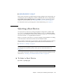
Sun Fire™ V445 Server
Administration Guide
Sun Microsystems, Inc.
www.sun.com
Part No. 819-3741-13
September 2007, Revision A
Submit comments about this document at: http://www.sun.com/hwdocs/feedback
Copyright 2007 Sun Microsystems, Inc., 4150 Network Circle, Santa Clara, California 95054, U.S.A. All rights reserved.
Sun Microsystems, Inc. has intellectual property rights relating to technology that is described in this document. In particular, and without
limitation, these intellectual property rights may include one or more of the U.S. patents listed at http://www.sun.com/patents and one or
more additional patents or pending patent applications in the U.S. and in other countries.
This document and the product to which it pertains are distributed under licenses restricting their use, copying, distribution, and
decompilation. No part of the product or of this document may be reproduced in any form by any means without prior written authorization of
Sun and its licensors, if any.
Third-party software, including font technology, is copyrighted and licensed from Sun suppliers.
Parts of the product may be derived from Berkeley BSD systems, licensed from the University of California. UNIX is a registered trademark in
the U.S. and in other countries, exclusively licensed through X/Open Company, Ltd.
Sun, Sun Microsystems, the Sun logo, Sun Fire, Solaris, VIS, Sun StorEdge, Solstice DiskSuite, Java, SunVTS and the Solaris logo are
trademarks or registered trademarks of Sun Microsystems, Inc. in the U.S. and in other countries.
All SPARC trademarks are used under license and are trademarks or registered trademarks of SPARC International, Inc. in the U.S. and in other
countries. Products bearing SPARC trademarks are based upon an architecture developed by Sun Microsystems, Inc.
The OPEN LOOK and Sun™ Graphical User Interface was developed by Sun Microsystems, Inc. for its users and licensees. Sun acknowledges
the pioneering efforts of Xerox in researching and developing the concept of visual or graphical user interfaces for the computer industry. Sun
holds a non-exclusive license from Xerox to the Xerox Graphical User Interface, which license also covers Sun’s licensees who implement OPEN
LOOK GUIs and otherwise comply with Sun’s written license agreements.
U.S. Government Rights – Commercial use. Government users are subject to the Sun Microsystems, Inc. standard license agreement and
applicable provisions of the FAR and its supplements.
DOCUMENTATION IS PROVIDED "AS IS" AND ALL EXPRESS OR IMPLIED CONDITIONS, REPRESENTATIONS AND WARRANTIES,
INCLUDING ANY IMPLIED WARRANTY OF MERCHANTABILITY, FITNESS FOR A PARTICULAR PURPOSE OR NON-INFRINGEMENT,
ARE DISCLAIMED, EXCEPT TO THE EXTENT THAT SUCH DISCLAIMERS ARE HELD TO BE LEGALLY INVALID.
Copyright 2007 Sun Microsystems, Inc., 4150 Network Circle, Santa Clara, California 95054, Etats-Unis. Tous droits réservés.
Sun Microsystems, Inc. a les droits de propriété intellectuels relatants à la technologie qui est décrit dans ce document. En particulier, et sans la
limitation, ces droits de propriété intellectuels peuvent inclure un ou plus des brevets américains énumérés à http://www.sun.com/patents et
un ou les brevets plus supplémentaires ou les applications de brevet en attente dans les Etats-Unis et dans les autres pays.
Ce produit ou document est protégé par un copyright et distribué avec des licences qui en restreignent l’utilisation, la copie, la distribution, et la
décompilation. Aucune partie de ce produit ou document ne peut être reproduite sous aucune forme, par quelque moyen que ce soit, sans
l’autorisation préalable et écrite de Sun et de ses bailleurs de licence, s’il y ena.
Le logiciel détenu par des tiers, et qui comprend la technologie relative aux polices de caractères, est protégé par un copyright et licencié par des
fournisseurs de Sun.
Des parties de ce produit pourront être dérivées des systèmes Berkeley BSD licenciés par l’Université de Californie. UNIX est une marque
déposée aux Etats-Unis et dans d’autres pays et licenciée exclusivement par X/Open Company, Ltd.
Sun, Sun Microsystems, le logo Sun, Sun Fire, Solaris, VIS, Sun StorEdge, Solstice DiskSuite, Java, SunVTS et le logo Solaris sont des
marques de fabrique ou des marques déposées de Sun Microsystems, Inc. aux Etats-Unis et dans d’autres pays.
Toutes les marques SPARC sont utilisées sous licence et sont des marques de fabrique ou des marques déposées de SPARC International, Inc.
aux Etats-Unis et dans d’autres pays. Les produits protant les marques SPARC sont basés sur une architecture développée par Sun
Microsystems, Inc.
L’interface d’utilisation graphique OPEN LOOK et Sun™ a été développée par Sun Microsystems, Inc. pour ses utilisateurs et licenciés. Sun
reconnaît les efforts de pionniers de Xerox pour la recherche et le développement du concept des interfaces d’utilisation visuelle ou graphique
pour l’industrie de l’informatique. Sun détient une license non exclusive de Xerox sur l’interface d’utilisation graphique Xerox, cette licence
couvrant également les licenciées de Sun qui mettent en place l’interface d ’utilisation graphique OPEN LOOK et qui en outre se conforment
aux licences écrites de Sun.
LA DOCUMENTATION EST FOURNIE "EN L’ÉTAT" ET TOUTES AUTRES CONDITIONS, DECLARATIONS ET GARANTIES EXPRESSES
OU TACITES SONT FORMELLEMENT EXCLUES, DANS LA MESURE AUTORISEE PAR LA LOI APPLICABLE, Y COMPRIS NOTAMMENT
TOUTE GARANTIE IMPLICITE RELATIVE A LA QUALITE MARCHANDE, A L’APTITUDE A UNE UTILISATION PARTICULIERE OU A
L’ABSENCE DE CONTREFAÇON.
Please
Recycle
Contents
Preface
1.
xxvii
System Overview
1
Sun Fire V445 Server Overview
Processors and Memory
External Ports
1
3
3
Gigabit Ethernet Ports
3
10BASE-T Network Management Port
Serial Management and DB-9 Ports
USB Ports
4
4
RAID 0,1 Internal Hard Drives
PCI Subsystem
5
Power Supplies
5
System Fan Trays
5
6
ALOM System Controller Card
6
Hardware Disk Mirroring and Striping
Predictive Self-Healing
New Features
4
6
6
7
Locating Front Panel Features
Front Panel Indicators
9
10
iii
Power Button
USB Ports
12
12
SAS Disk Drives
14
Removable Media Drive
14
Locating Back Panel Features
Back Panel Indicators
Power Supplies
PCI Slots
16
17
17
17
System Controller Ports
19
Network Management Port
Serial Management Port
System I/O Ports
USB Ports
19
20
20
20
Gigabit Ethernet Ports
DB-9 Serial Port
20
21
Reliability, Availability, and Serviceability (RAS) Features
Sun Cluster Software
22
Sun Management Center Software
2.
22
Configuring the System Console
23
25
About Communicating With the System
About Using the System Console
26
27
Default System Console Connection Through the Serial Management and
Network Management Ports 29
Access Through the Network Management Port
ALOM
30
30
Alternative System Console Configuration
31
Accessing the System Console Through a Graphics Monitor
About the sc> Prompt
iv
32
Sun Fire V445 Server Administration Guide • September 2007
32
Access Through Multiple Controller Sessions
Ways of Reaching the sc> Prompt
About the ok Prompt
34
34
35
Entering the ok Prompt
35
Graceful Shutdown
36
ALOM System Controller break or console Command
L1-A (Stop-A) Keys or Break Key
Externally Initiated Reset (XIR)
Manual System Reset
36
37
37
37
About Switching Between the ALOM System Controller and the System
Console 38
Entering the ok Prompt
▼
40
To Enter the ok Prompt
40
Using the Serial Management Port
▼
41
To Use the Serial Management Port
Activating the Network Management Port
▼
42
42
To Activate the Network Management Port
43
Accessing the System Console With a Terminal Server
44
▼
To Access the System Console With a Terminal Server Through the Serial
Management Port 44
▼
To Access the System Console With a Terminal Server Through the TTYB
Port 46
What Next
47
Accessing the System Console With a Tip Connection
47
▼
To Access the System Console With a Tip Connection Throught the Serial
Management Port 48
▼
To Access the System Console With a Tip Connection Through the TTYB
Port 49
Modifying the /etc/remote File
▼
51
To Modify the /etc/remote File
51
Contents
v
Accessing the System Console With an Alphanumeric Terminal
53
▼
To Access the System Console With an Alphanumeric Terminal Through
the Serial Management Port 53
▼
To Access the System Console With an Alphanumeric Terminal Through
the TTYB Port 54
Verifying Serial Port Settings on TTYB
▼
55
To Verify Serial Port Settings on TTYB
55
Accessing the System Console With a Local Graphics Monitor
▼
56
To Access the System Console With a Local Graphics Monitor
56
Reference for System Console OpenBoot Configuration Variable Settings
3.
Powering On and Powering Off the System
Before You Begin
62
To Power On the Server Remotely
Powering On the Server Locally
▼
To Power On the Server Locally
63
64
▼
To Power Off the System Remotely From the ok Prompt
▼
To Power Off the System Remotely From the ALOM System Controller
Prompt 65
Powering Off the Server Locally
▼
66
To Power Off the Server Locally
Initiating a Reconfiguration Boot
▼
▼
69
To Select a Boot Device
Configuring Hardware
66
66
To Initiate a Reconfiguration Boot
Selecting a Boot Device
70
73
About the CPU/Memory Modules
vi
62
63
Powering Off the System Remotely
4.
61
61
Powering On the Server Remotely
▼
59
73
Sun Fire V445 Server Administration Guide • September 2007
67
65
DIMMs
74
Memory Interleaving
76
Independent Memory Subsystems
DIMM Configuration Rules
76
77
About the ALOM System Controller Card
Configuration Rules
77
80
About the PCI Cards and Buses
Configuration Rules
81
84
About the SAS Controller
84
About the SAS Backplane
85
Configuration Rules
85
About Hot-Pluggable and Hot-Swappable Components
Hard Disk Drives
Power Supplies
86
86
System Fan Trays
87
USB Components
87
About the Internal Disk Drives
Configuration Rules
87
89
About the Power Supplies
89
Performing a Power Supply Hot-Swap Operation
Power Supply Configuration Rules
About the System Fan Trays
5.
92
94
95
Configuration Rules
About the Serial Ports
91
92
System Fan Configuration Rules
About the USB Ports
85
95
96
Managing RAS Features and System Firmware
97
About Reliability, Availability, and Serviceability Features
98
Contents
vii
Hot-Pluggable and Hot-Swappable Components
n+2 Power Supply Redundancy
ALOM System Controller
98
99
99
Environmental Monitoring and Control
Automatic System Restoration
101
Sun StorEdge Traffic Manager
102
100
Hardware Watchdog Mechanism and XIR
102
Support for RAID Storage Configurations
102
Error Correction and Parity Checking
103
About the ALOM System Controller Command Prompt
Logging In to the ALOM System Controller
▼
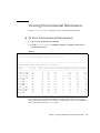
107
To View Environmental Information
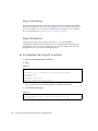
Controlling the Locator Indicator
▼
105
106
Viewing Environmental Information
▼
104
To Log In to the ALOM System Controller
About the scadm Utility
107
108
To Control the Locator Indicator
108
About Performing OpenBoot Emergency Procedures
Stop-A Function
110
Stop-N Function
110
▼
To Emulate the Stop-N Function
Stop-F Function
111
Stop-D Function
111
About Automatic System Restoration
Unconfiguring a Device Manually
▼
viii
110
111
112
To Unconfigure a Device Manually
Reconfiguring a Device Manually
▼
103
112
114
To Reconfigure a Device Manually
Sun Fire V445 Server Administration Guide • September 2007
114
109
Enabling the Hardware Watchdog Mechanism and Its Options
▼
To Enable the Hardware Watchdog Mechanism and Its Options
About Multipathing Software
6.
114
Managing Disk Volumes
About Disk Volumes
115
117
118
About Volume Management Software
VERITAS Dynamic Multipathing
Sun StorEdge Traffic Manager
About RAID Technology
Disk Concatenation
118
119
119
120
120
RAID 0: Disk Striping or Intergated Stripe (IS)
121
RAID 1: Disk Mirroring or Integrated Mirror (IM)
Hot-Spares
115
121
122
About Hardware Disk Mirroring
122
About Physical Disk Slot Numbers, Physical Device Names, and Logical Device
Names 123
Creating a Hardware Disk Mirror
▼
124
To Create a Hardware Disk Mirror
124
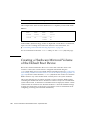
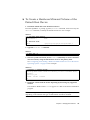
Creating a Hardware Mirrored Volume of the Default Boot Device
▼
126
To Create a Hardware Mirrored Volume of the Default Boot Device
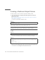
Creating a Hardware Striped Volume
127
128
Configuring and Labeling a Hardware RAID Volume for Use in the Solaris
Operating System 129
Deleting a Hardware Disk Mirror
▼
132
To Delete a Hardware Disk Mirror
133
Performing a Mirrored Disk Hot-Plug Operation
▼
134
To Perform a Mirrored Disk Hot-Plug Operation
Performing a Nonmirrored Disk Hot-Plug Operation
▼
To View the Status of the SCSI Devices
134
136
136
Contents
ix
▼
7.
To Perform a Nonmirrored Disk Hot-Plug Operation
Managing Network Interfaces
About the Network Interfaces
141
141
About Redundant Network Interfaces
142
Attaching a Twisted-Pair Ethernet Cable
▼
143
To Attach a Twisted-Pair Ethernet Cable
Configuring the Primary Network Interface
▼
8.
143
144
To Configure the Primary Network Interface
Configuring Additional Network Interfaces
▼
144
145
To Configure Additional Network Interfaces
Diagnostics
146
151
Diagnostic Tools Overview
152
About Sun Advanced Lights-Out Manager 1.0 (ALOM)
ALOM Management Ports
Basic ALOM Functions
155
156
▼
To Switch to the ALOM Prompt
▼
To Switch to the Server Console Prompt
About Status Indicators
About POST Diagnostics
154
155
Setting the admin Password for ALOM
156
156
157
157
OpenBoot PROM Enhancements for Diagnostic Operation
What’s New in Diagnostic Operation
About the Default Configuration
About Service Mode
159
162
About Initiating Service Mode
163
About Overriding Service Mode Settings
Sun Fire V445 Server Administration Guide • September 2007
158
158
About the New and Redefined Configuration Variables
x
138
164
158
About Normal Mode
164
About Initiating Normal Mode
About the post Command
165
165
▼
To Initiate Service Mode
167
▼
To Initiate Normal Mode
167
Reference for Estimating System Boot Time (to the ok Prompt)
Boot Time Estimates for Typical Configurations
Estimating Boot Time for Your System
Reference for Sample Outputs
170
Quick Reference for Diagnostic Operation
▼
172
175
176
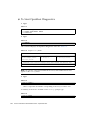
To Start OpenBoot Diagnostics
177
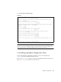
Controlling OpenBoot Diagnostics Tests
test and test-all Commands
178
179
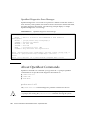
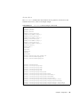
OpenBoot Diagnostics Error Messages
About OpenBoot Commands
probe-scsi-all
▼
169
169
Reference for Determining Diagnostic Mode
OpenBoot Diagnostics
168
probe-ide
182
show-devs
184
180
181
181
To Run OpenBoot Commands
About Predictive Self-Healing
185
185
Predictive Self-Healing Tools
186
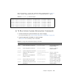
Using the Predictive Self-Healing Commands
Using the fmdump Command
187
Using the fmadm faulty Command
Using the fmstat Command
187
189
189
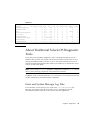
About Traditional Solaris OS Diagnostic Tools
190
Contents
xi
Error and System Message Log Files
190
Solaris System Information Commands
Using the prtconf Command
192
Using the prtdiag Command
192
Using the prtfru Command
▼
197
Using the psrinfo Command
201
Using the showrev Command
201
To Run Solaris System Information Commands
Viewing Recent Diagnostic Test Results
▼
To View Recent Test Results
202
203
203
Setting OpenBoot Configuration Variables
▼
191
203
To View and Set OpenBoot Configuration Variables
Additional Diagnostic Tests for Specific Devices
204
205
Using the probe-scsi Command to Confirm That Hard Disk Drives are
Active 205
Using the probe-ide Command To Confirm That the DVD Drive is
Connected 206
Using the watch-net and watch-net-all Commands to Check the
Network Connections 206
About Automatic Server Restart
207
About Automatic System Restoration
Auto-Boot Options
▼
209
To Set the Auto-Boot Switches
Error Handling Summary
Reset Scenarios
208
209
210
211
Automatic System Restoration User Commands
Enabling Automatic System Restoration
Disabling Automatic System Restoration
▼
212
212
212
To Disable Automatic System Restoration
212
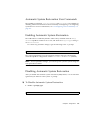
Displaying Automatic System Restoration Information
xii
Sun Fire V445 Server Administration Guide • September 2007
213
About SunVTS
214
SunVTS Software and Security
Using SunVTS
▼
214
215
To Find Out Whether SunVTS Is Installed
Installing SunVTS
216
216
Viewing SunVTS Documentation
About Sun Management Center
216
217
How Sun Management Center Works
Using Sun Management Center
218
219
Other Sun Management Center Features
Informal Tracking
219
219
Hardware Diagnostic Suite
220
Interoperability With Third-Party Monitoring Tools
Obtaining the Latest Information
Hardware Diagnostic Suite
220
220
When to Run Hardware Diagnostic Suite
220
Requirements for Using Hardware Diagnostic Suite
9.
Troubleshooting
223
About Updated Troubleshooting Information
Web Sites
221
223
Troubleshooting Options
Product Notes
220
224
224
224
SunSolve Online
Big Admin
224
225
About Firmware and Software Patch Management
About Sun Install Check Tool
225
226
About Sun Explorer Data Collector
226
About Sun Remote Services Net Connect
227
Contents
xiii
About Configuring the System for Troubleshooting
Hardware Watchdog Mechanism
227
Automatic System Restoration Settings
Remote Troubleshooting Capabilities
System Console Logging
Predictive Self-Healing
Core Dump Process
A.
229
230
230
231
To Enable the Core Dump Process
Testing the Core Dump Setup
▼
228
229
Enabling the Core Dump Process
▼
231
233
To Test the Core Dump Setup
Connector Pinouts
227
233
235
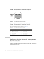
Reference for the Serial Management Port Connector
Serial Management Connector Diagram
Serial Management Connector Signals
235
236
236
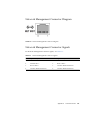
Reference for the Network Management Port Connector
Network Management Connector Diagram
Network Management Connector Signals
Reference for the Serial Port Connector
Serial Port Connector Diagram
238
Reference for the USB Connectors
239
USB Connector Signals
238
239
239
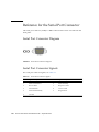
Reference for the Gigabit Ethernet Connectors
Gigabit Ethernet Connector Diagram
Gigabit Ethernet Connector Signals
241
xiv
237
238
Serial Port Connector Signals
USB Connector Diagram
237
Sun Fire V445 Server Administration Guide • September 2007
240
241
240
236
B.
System Specifications
243
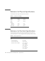
Reference for Physical Specifications
Reference for Electrical Specifications
244
244
Reference for Environmental Specifications
245
Reference for Agency Compliance Specifications
246
Reference for Clearance and Service Access Specifications
C.
OpenBoot Configuration Variables
Index
247
249
253
Contents
xv
xvi
Sun Fire V445 Server Administration Guide • September 2007
Figures
FIGURE 1-1
Front Panel Features
9
FIGURE 1-2
Front Panel System Status Indicators
FIGURE 1-3
Power Button Location
FIGURE 1-4
USB Ports Location
FIGURE 1-5
Hard Disk Drives Location
FIGURE 1-6
Removable Media Drive Location
FIGURE 1-7
Back Panel Features
FIGURE 1-8
PCI Slot Locations
FIGURE 1-9
Network and Serial Management Port Locations
FIGURE 1-10
System I/O Port Locations
FIGURE 1-11
Gigabit Ethernet Port Locations
FIGURE 2-1
Directing the System Console to Different Ports and Different Devices
FIGURE 2-2
Serial Management Port (Default Console Connection)
FIGURE 2-3
Separate System Console and System Controller Channels
FIGURE 2-4
Patch Panel Connection Between a Terminal Server and a Sun Fire V445 Server
FIGURE 2-7
Tip Connection Between a Sun Fire V445 Server and Another Sun System
FIGURE 4-1
Memory Module Groups 0 and 1
FIGURE 4-2
ALOM System Controller Card
FIGURE 4-3
ALOM System Controller Card Ports
FIGURE 4-4
PCI Slots
10
12
13
14
15
17
18
19
20
21
28
29
39
45
48
75
78
80
83
xvii
FIGURE 4-5
Hard Disk Drives and Indicators
FIGURE 4-6
Power Supplies and Indicators
FIGURE 4-7
System Fan Trays and Fan Indicators
FIGURE 8-7
Diagnostic Mode Flowchart
FIGURE A-1
Serial Management Connector Diagram
FIGURE A-2
Network Management Connector Diagram
FIGURE A-3
Serial Port Connector Diagram
FIGURE A-4
USB Connector Diagram
FIGURE A-5
Gigabit Ethernet Connector Diagram
xviii
88
90
93
175
236
237
238
239
241
Sun Fire V445 Server Administration Guide • September 2007
Tables
TABLE 1-1
Sun Fire V445 Server Features at a Glance
TABLE 1-2
System Status Indicators
TABLE 1-3
System Diagnostic Indicators
TABLE 1-4
Network Management Port Indicator
TABLE 1-5
Ethernet Indicators
TABLE 2-1
Ways of Communicating With the System
TABLE 2-2
TABLE 2-3
11
19
21
Ways of Accessing the ok Prompt
26
41
42
TABLE 2-4
42
TABLE 2-5
43
TABLE 2-6
43
TABLE 2-7
43
TABLE 2-8
44
Pin Crossovers for Connecting to a Typical Terminal Server
TABLE 5
46
TABLE 6
46
TABLE 2-10
46
2.
Table 2-11
11
36
2.
TABLE 2-9
2
45
47
49
xix
Table 2-12
49
TABLE 2-13
49
2.
50
Table 2-14
51
Table 2-15
51
Table 2-16
52
TABLE 2-17
54
2.
54
Table 2-18
55
Table 2-19
55
8.
TABLE 2-20
58
OpenBoot Configuration Variables That Affect the System Console
TABLE 3-1
62
TABLE 3-2
65
TABLE 3-3
65
TABLE 3-4
68
7.
59
68
TABLE 3-5
68
TABLE 3-6
68
l
70
Note –
70
TABLE 4-1
Memory Module Groups 0 and 1
TABLE 4-2
PCI Bus Characteristics, Associated Bridge Chips, Motherboard Devices,
and PCI Slots 82
TABLE 4-3
PCI Slot Device Names and Paths
TABLE 4-4
Hard Disk Drive Status Indicators
TABLE 4-5
Power Supply Status Indicators
TABLE 4-6
Fan Tray Status Indicators
TABLE 5-1
104
TABLE 5-2
105
xx
75
83
88
90
93
Sun Fire V445 Server Administration Guide • September 2007
TABLE 5-3
105
TABLE 5-4
106
TABLE 5-5
107
TABLE 5-6
108
TABLE 5-7
108
TABLE 5-8
108
TABLE 5-9
109
TABLE 5-10
109
TABLE 5-11
109
TABLE 5-12
110
TABLE 5-13
110
TABLE 5-14
111
1.
TABLE 5-15
112
Device Identifiers and Devices
n
113
n
113
n
113
2.
113
1.
114
1.
115
TABLE 5-16
TABLE 6-1
112
115
4.
115
5.
115
Disk Slot Numbers, Logical Device Names, and Physical Device Names
TABLE 6-2
124
TABLE 6-3
125
TABLE 6-4
125
TABLE 6-5
125
TABLE 6-6
125
TABLE 6-7
126
124
Tables
xxi
TABLE 6-8
127
TABLE 6-9
127
TABLE 6-10
127
TABLE 6-11
128
TABLE 6-12
128
TABLE 6-13
128
TABLE 6-14
129
TABLE 6-15
129
TABLE 6-16
130
TABLE 6-17
130
TABLE 6-18
131
TABLE 6-19
131
TABLE 6-20
132
TABLE 6-21
133
TABLE 6-22
133
TABLE 6-23
133
TABLE 6-24
133
TABLE 6-25
133
TABLE 6-26
134
TABLE 6-27
134
TABLE 6-28
135
TABLE 6-29
135
TABLE 6-30
135
TABLE 6-31
136
TABLE 6-32
136
TABLE 6-33
137
TABLE 6-34
138
TABLE 6-35
138
TABLE 6-36
138
TABLE 6-37
139
xxii
Sun Fire V445 Server Administration Guide • September 2007
TABLE 6-38
139
TABLE 6-39
139
TABLE 8-1
Summary of Diagnostic Tools
TABLE 8-2
What ALOM Monitors
TABLE 8-3
156
TABLE 8-4
156
TABLE 8-5
156
TABLE 8-6
156
152
154
TABLE 8-7
OpenBoot Configuration Variables That Control Diagnostic Testing and Automatic System
Restoration 160
TABLE 8-8
Service Mode Overrides
TABLE 8-9
Scenarios for Overriding Service Mode Settings
TABLE 1
167
TABLE 2
167
TABLE 3
167
TABLE 4
167
TABLE 5
171
TABLE 6
172
TABLE 8-10
Summary of Diagnostic Operation
TABLE 8-11
177
TABLE 8-12
177
TABLE 8-13
Sample obdiag Menu
TABLE 8-14
177
TABLE 8-15
177
TABLE 8-16
178
TABLE 8-17
163
164
175
177
Keywords for the test-args OpenBoot Configuration Variable
TABLE 8-18
179
TABLE 8-19
179
TABLE 8-20
180
TABLE 8-21
180
179
Tables
xxiii
TABLE 8-22
TABLE 8-23
180
System Generated Predictive Self-Healing Message
TABLE 8-24
188
TABLE 8-25
188
TABLE 8-26
188
TABLE 8-27
189
TABLE 8-28
189
TABLE 8-29
190
TABLE 8-30
showrev -p Command Output
TABLE 8-31
Using Solaris Information Display Commands
TABLE 8-32
203
TABLE 8-33
204
TABLE 8-34
204
1.
n
186
202
202
209
212
l
1.
212
2.
213
213
TABLE 8-35
SunVTS Tests
TABLE 8-36
216
TABLE 8-37
216
215
TABLE 8-38
What Sun Management Center Monitors
TABLE 8-39
Sun Management Center Features
TABLE 9-1
OpenBoot Configuration Variable Settings to Enable Automatic System Restoration
TABLE 9-2
231
TABLE 9-3
232
TABLE 9-4
232
TABLE 9-5
232
TABLE 9-6
233
TABLE 9-7
233
xxiv
217
218
Sun Fire V445 Server Administration Guide • September 2007
228
TABLE A-1
Serial Management Connector Signals
236
TABLE A-2
Network Management Connector Signals
TABLE A-3
Serial Port Connector Signals
TABLE A-4
USB Connector Signals
TABLE A-5
Gigabit Ethernet Connector Signals
TABLE B-1
Dimensions and Weight
TABLE B-2
Electrical Specifications
TABLE B-3
Environmental Specifications
TABLE B-4
Agency Compliance Specifications
TABLE B-5
Clearance and Service Access Specifications
TABLE C-1
OpenBoot Configuration Variables Stored on a ROM Chip
237
238
239
241
244
244
245
246
247
249
Tables
xxv
xxvi
Sun Fire V445 Server Administration Guide • September 2007
Preface
The Sun Fire V445 Server Administration Guide is intended for experienced system
administrators. It includes general descriptive information about the Sun Fire TM
V445 server and detailed instructions for configuring and administering the server.
To use the information in this manual, you must have working knowledge of
computer network concepts and terms, and advanced familiarity with the Solaris™
Operating System (OS).
How This Book Is Organized
The Sun Fire V445 Server Administration Guide is divided into the following chapters:
■
Chapter 1 presents an illustrated overview of the system and a description of the
system’s reliability, availability, and serviceability (RAS) features, as well as new
features introduced with this server.
■
Chapter 2 describes the system console and how to access it.
■
Chapter 3 describes how to power on and power off the system, and how to
initiate a reconfiguration boot.
■
Chapter 4 describes and illustrates system hardware components. It also includes
configuration information for CPU/Memory modules and DIMMs.
■
Chapter 5 describes the tools used to configure system firmware, including Sun TM
Advanced Lights Out Manager (ALOM) system controller environmental
monitoring, automatic system recovery (ASR), hardware watchdog mechanism,
and multipathing software. In addition, it describes how to unconfigure and
reconfigure a device manually.
■
Chapter 6 describes how to manage internal disk volumes and devices.
■
Chapter 7 provides instructions for configuring network interfaces.
xxvii
■
Chapter 8 describes how to perform system diagnostics.
■
Chapter 9 describes how to troubleshoot the system.
This manual also includes the following appendices:
■
Appendix A details connector pinouts.
■
Appendix B provides tables of various system specifications.
■
Appendix C provides a list of all OpenBoot™ configuration variables, and a short
description of each.
Using UNIX Commands
This document might not contain information about basic UNIX ® commands and
procedures such as shutting down the system, booting the system, and configuring
devices.
See one or more of the following for this information:
xxviii
■
Online documentation for the Solaris OS at docs.sun.com
■
Other software documentation that you received with your system
Sun Fire V445 Server Administration Guide • September 2007
Typographic Conventions
TABLE P-1
Typeface*
Meaning
Examples
AaBbCc123
The names of commands, files,
and directories; on-screen
computer output
Edit your.login file.
Use ls -a to list all files.
% You have mail.
AaBbCc123
What you type, when contrasted % su
with on-screen computer output Password:
AaBbCc123
Book titles, new words or terms,
words to be emphasized
Read Chapter 6 in the User’s Guide.
These are called class options.
You must be superuser to do this.
AaBbCc123
Command-line variable; replace
with a real name or value
To delete a file, type rm filename.
* The settings on your browser might differ from these settings.
System Prompts
TABLE P-2
Type of Prompt
Prompt
C shell
machine-name%
C shell superuser
machine-name#
Bourne shell and Korn shell
$
Bourne shell and Korn shell superuser
#
ALOM system controller
sc>
OpenBoot firmware
ok
OpenBoot Diagnostics
obdiag>
Preface
xxix
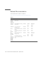
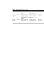
Related Documentation
The documents listed as online are available at:
http://www.sun.com/products-n-solutions/hardware/docs/
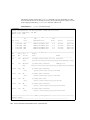
TABLE P-3
Application
Title
Part Number
Format
Location
Latebreaking
product
information
Sun Fire V445 Server
Product Notes
819-3744
PDF
Online
Installation
overview
Sun Fire V445 Server Getting
Started Guide
819-4664
Printed
Shipping kit
PDF
Online
Installation
Sun Fire V445 Server
Installation Guide
819-3743
PDF
Online
Service
Sun Fire V445 Server Service
Manual
819-3742
PDF
Online
Site
planning
Site Planning Guide for Sun
Servers
819-5730
PDF
Online
Site
planning
data sheet
Sun Fire V445 Server Site
Planning Guide
819-3745
Printed
Shipping kit
PDF
Online
Sun
Advanced
Lights Out
Manager
(ALOM)
system
controller
Sun Advanced Lights Out
Manager (ALOM) 1.6 Online
Help
PDF
Online
xxx Sun Fire V445 Server Administration Guide • September 2007
817-1960
Documentation, Support, and Training
Sun Function
URL
Documentation
http://www.sun.com/documentation/
Support
http://www.sun.com/support/
Training
http://www.sun.com/training/
Third-Party Web Sites
Sun is not responsible for the availability of third-party web sites mentioned in this
document. Sun does not endorse and is not responsible or liable for any content,
advertising, products, or other materials that are available on or through such sites
or resources. Sun will not be responsible or liable for any actual or alleged damage
or loss caused by or in connection with the use of or reliance on any such content,
goods, or services that are available on or through such sites or resources.
Sun Welcomes Your Comments
Sun is interested in improving its documentation and welcomes your comments and
suggestions. You can submit your comments by going to:
http://www.sun.com/hwdocs/feedback
Please include the title and part number of your document with your feedback:
Sun Fire V445 Server Administration Guide, part number 819-3741
Preface
xxxi
xxxii Sun Fire V445 Server Administration Guide • September 2007
CHAPTER
1
System Overview
This chapter introduces you to the Sun Fire V445 server and describes its features.
The following sections are included:
■
■
■
■
■
■
■
“Sun Fire V445 Server Overview” on page 1
“New Features” on page 7
“Locating Front Panel Features” on page 9
“Locating Back Panel Features” on page 16
“Reliability, Availability, and Serviceability (RAS) Features” on page 22
“Sun Cluster Software” on page 22
“Sun Management Center Software” on page 23
Note – This document does not provide instructions for installing or removing
hardware components. For instructions on preparing the system for servicing and
procedures to install and remove the server components described in this document,
refer to the Sun Fire V445 Server Service Manual.
Sun Fire V445 Server Overview
The Sun Fire V445 server is a high-performance, shared memory, symmetric
multiprocessing server that supports up to four UltraSPARC® IIIi processors and
uses the Fire ASIC PCIe NorthBridge along with PCI-X and PCIe expansion slots.
The UltraSPARC IIIi processor has a 1 Mbyte L2 cache and implements the SPARC®
V9 Instruction Set Architecture (ISA) and the Visual Instruction Set extensions (Sun
VIS software) that accelerate multimedia, networking, encryption, and Java™
software processing. The Fire ASIC provides higher I/O performance and interfaces
with the I/O subsystem, which contains 4 10/100/1000Mb Ethernet ports, 8 SAS
disk drives, 1 DVD-RW drive, 4 USB ports, a POSIX compliant DB-9 serial port, and
service processor communication ports. The PCI expansion subsystem is
configurable with a variety of plug-in third party adapters.
1
System reliability, availability, and serviceability (RAS) are enhanced by features that
include hot-pluggable disk drives and redundant, hot-swappable power supplies
and fan trays. RAS features are described in Chapter 5.
The system, which is mountable in a 4-post rack, measures 6.85 inches high (4 rack
units - U), 17.48 inches wide, and 25 inches deep (17.5 cm x 44.5 cm x 64.4 cm). The
system weighs approximately 75 lb (34.02 kg). Robust remote access is provided
with Advanced Lights Out Manager (ALOM) software, which also controls
powering on/off and diagnostics. The system also meets ROHS requirements.
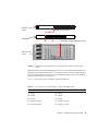
TABLE 1-1 provides a brief description of the Sun Fire V445 server features. More
details on these features are provided in the following subsections.
TABLE 1-1
2
Sun Fire V445 Server Features at a Glance
Feature
Description
Processor
4 UltraSPARC IIIi CPUs
Memory
16 slots that can be populated with one of the following types of
DDR1 DIMMS:
• 512 MB (8 GB maximum)
• 1 GB (16 GB maximum)
• 2 GB (32 GB maximum)
External ports
• 4 Gigabit Ethernet ports – Support several modes of operations at
10, 100, and 1000 megabits per second (Mbps)
• 1 10BASE-T network management port – Reserved for the ALOM
system controller and the system console
• 2 Serial ports – One POSIX compliant DB-9 connector, and one RJ45 serial management connector on the ALOM system controller
card
• 4 USB ports – USB 2.0 compliant and support 480 Mbps, 12 Mbps,
and 1.5 Mbps speeds
Internal hard drives
8 2.5 inch (5.1 cm) high, hot-pluggable Serial Attached SCSI (SAS)
disk drives
Other internal
peripherals
1 DVD/ROM/RW device
PCI interfaces
8 PCI slots: four 8 lane PCIe slots (2 of which also support 16 lane
form factor cards) and 4 PCI-X slots
Power
4 550-watt hot-swappable power supplies, each with its own cooling
fan
Cooling
6 hot-swappable high-power fan trays (one fan per tray) organized
into three redundant pairs – 1 redundant pair for disk drives – 2
redundant pairs for the CPU/memory modules, memory DIMMs,
I/O subsystem, and front-to-rear cooling of the system
Sun Fire V445 Server Administration Guide • September 2007
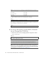
TABLE 1-1
Sun Fire V445 Server Features at a Glance (Continued)
Feature
Description
Remote management
A serial port for the ALOM management controller card and a
10BASE-T network management port for remote access to system
functions and the system controller
Disk Mirroring
Hardware RAID 0,1 support for internal disk drives
RAS features
Robust reliability, availability, and serviceability (RAS) features are
supported. See Chapter 5 for details.
Firmware
Sun system firmware containing:
• OpenBoot PROM for system settings and power-on self-test
(POST) support
• ALOM for remote management administration
Operating system
The Solaris OS is preinstalled on disk 0.
Processors and Memory
Processing power is provided by up to four CPU/Memory modules. Each module
incorporates one UltraSPARC IIIi processor, and slots for four double data rate
(DDR) dual inline memory modules (DIMMs).
System main memory is provided by up to 16 DDR synchronous dynamic random
access memory DIMMs. The system supports 512-Mbyte, 1-Gbyte, and 2-Gbyte
DIMMs. Total system memory is shared by all CPUs in the system and ranges from
a minimum of 1 Gbyte (one CPU/memory module with two 512-Mbyte DIMMs) to
a maximum of 32 Gbytes (four modules fully populated with 2-Gbyte DIMMs). For
more information about system memory, see “DIMMs” on page 74.
External Ports
The Sun Fire V445 server provides four Gigabit Ethernet ports, one 10BASE-T
network management port, two Serial ports, and four USB ports.
Gigabit Ethernet Ports
The four on-board Gigabit Ethernet ports located on the back panel support several
modes of operations at 10, 100, and 1000 megabits per second (Mbps). Additional
Ethernet interfaces or connections to other network types can be provided by
installing the appropriate PCI interface cards. Multiple network interfaces can be
combined with Solaris Internet Protocol (IP) network multipathing software to
Chapter 1
System Overview
3
provide hardware redundancy and failover capability, as well as load balancing on
outbound traffic. Should one of the interfaces fail, the software can automatically
switch all network traffic to an alternate interface to maintain network availability.
For more information about network connections, see “Configuring the Primary
Network Interface” on page 144 and “Configuring Additional Network Interfaces”
on page 145.
10BASE-T Network Management Port
The network management port (labeled NET MGT) is located on the chassis back
panel. This port is reserved for use with the ALOM system controller and the system
console.
This port provides direct network access to the ALOM system controller card and its
firmware. This port also provides access to the system console, power-on self-test
(POST) output messages, and ALOM system controller messages. Use this port to
perform remote administration, including externally initiated resets (XIR).
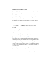
Serial Management and DB-9 Ports
The DB-9 port is POSIX compliant with a general-purpose DB-9 connector (labeled
TTYB) on the system back panel. The serial management port is an RJ-45 connector
(labeled SERIAL MGT) on the chassis back panel, and is reserved for use with the
ALOM system controller and the system console.
The serial management port enables you to set up a system console device, without
configuring an existing port. All power-on self-test (POST) and ALOM system
controller messages are directed to the serial management port by default. For more
information, see “About the Serial Ports” on page 96.
USB Ports
The front and back panels both provide two Universal Serial Bus (USB) ports for
connecting peripheral devices such as modems, printers, scanners, digital cameras,
or a Sun Type-6 USB keyboard and mouse. The USB ports are USB 2.0 compliant,
and support 480 Mbps, 12 Mbps, and 1.5 Mbps speeds. For additional details, see
“About the USB Ports” on page 95.
4
Sun Fire V445 Server Administration Guide • September 2007
RAID 0,1 Internal Hard Drives
Internal disk storage is provided by up to eight 2.5 inch (5.1 cm) high, hot-pluggable,
SAS disk drives. The basic system includes a SAS disk backplane that accommodates
eight disks capable of data transfer rates of up to 320 megabytes per second. See
“About the Internal Disk Drives” on page 87 and “Locating Back Panel Features” on
page 16.
External multidisk storage subsystems and redundant array of independent disks
(RAID) storage arrays can be supported by installing peripheral component
interconnect (PCI) host adapter cards along with the appropriate system software.
Software drivers supporting SCSI and other types of devices are included in the
Solaris OS. In addition, the system supports internal hardware mirroring (RAID 0,1)
using the on-board SAS controller. See “About RAID Technology” on page 120.
PCI Subsystem
System I/O is handled by two expanded Peripheral Component Interconnect (PCIe)
buses and two PCI-X buses. The system has eight PCI slots: four 8 lane PCIe slots
(two of which also support 16 lane form factor cards) and four PCI-X slots. The PCIX slots operate at up to 133 MHz, are 64-bit capable, and support legacy PCI devices.
All PCI-X slots comply with PCI Local Bus Specification Rev 2.2 and PCI-X Local
Bus Specification Rev 1.0. All PCIe slots comply with PCIe Base Specification r1.0a
and PCI Standard SHPC Specification, r1.1. For additional details, see “About the
PCI Cards and Buses” on page 81.
Power Supplies
The basic system includes four 550-watt power supplies, each with its own cooling
fan. The power supplies are plugged into a separate power distribution board (PDB).
This board is connected to the motherboard through 12-volt high current bus bars.
Two power supplies provide sufficient current (1100 DC watts) for maximum
configuration. The other power supplies provide 2+2 redundancy, enabling the
system to continue operating if up to two power supplies fail.
The power supplies are hot-swappable – you can remove and replace a faulty power
supply without shutting down the system. With four separate AC inlets you can
wire the server with a fully redundant AC circuit. A failed power supply does not
need to remain installed to sustain proper cooling. For more information about the
power supplies, see “About the Power Supplies” on page 89.
Chapter 1
System Overview
5
System Fan Trays
The system is equipped with six fan trays organized into three redundant pairs. One
redundant pair is for cooling the disk drives. The other two redundant pairs are for
cooling the CPU/Memory modules, memory DIMMs, I/O subsystem, and provide
front-to-rear cooling of the system. Not all fans must be present to provide adequate
cooling – only one fan per redundant pair must be present.
Note – All system cooling is provided by the fan trays – power supply fans do not
provide system cooling.
See “About the System Fan Trays” on page 92 for details.
ALOM System Controller Card
The Sun ALOM system controller card enables system management and
administration for the Sun Fire V445 server over a serial line or an Ethernet network.
The ALOM system controller provides remote system administration for
geographically distributed or physically inaccessible systems. These features include
powering on/off the system and enabling diagnostics. The firmware installed on the
ALOM system controller card enables you to monitor the system, without having to
install any supporting software.
The ALOM system controller card runs independently of the host system, and
operates off of standby power from the systems power supplies. This allows the
ALOM system controller to serve as a lights out management tool that continues to
function even when the server operating system goes offline or when the server is
powered off.
Hardware Disk Mirroring and Striping
The SAS controller supports hardware disk mirroring and striping (RAID 0,1)
capabilities for all internal disk drives, resulting in improved disk drive
performance, data integrity, data availability, and fault recovery.
Predictive Self-Healing
Sun Fire V445 servers with Solaris 10 or later feature the latest fault management
technologies. With Solaris 10, Sun introduces a new architecture for building and
deploying systems and services capable of predictive self-healing. Self-healing
6
Sun Fire V445 Server Administration Guide • September 2007
technology enables Sun systems to accurately predict component failures and
mitigate many serious problems before they actually occur. This technology is
incorporated into both the hardware and software of the Sun Fire V445 server.
At the heart of the Predictive Self-Healing capabilities is the Solaris™ Fault Manager,
a service that receives data relating to hardware and software errors, and
automatically and silently diagnoses the underlying problem. Once a problem is
diagnosed, a set of agents automatically responds by logging the event, and if
necessary, takes the faulty component offline. By automatically diagnosing
problems, business-critical applications and essential system services can continue
uninterrupted in the event of software failures, or major hardware component
failures.
New Features
The Sun Fire V445 server provides faster computing in a denser, more powerefficient package. The following key new features are included:
■
UltraSPARC IIIi CPU
The UltraSPARC IIIi CPU provides a faster JBus system interface bus that
considerably enhances system performance.
■
Higher I/O Performance With Fire ASIC, PCIe, and PCI-X
The Sun Fire V445 server provides higher I/O performance with PCIe cards
integrated with the latest Fire chip (NorthBridge). This integration allows higher
bandwidth and lower latency datapaths between the I/O subsystem and the
CPUs. The server supports two full height or low profile/full depth 16 lane
(wired 8 lane) PCIe cards and two full height or low profile/half depth 8 lane
PCIe cards. The system also supports four PCI-X slots that operate at up to 133
MHz, are 64-bit capable, and support legacy PCI cards.
The Fire ASIC is a high-performance JBus to PCIe host bridge. On the host bus
side, Fire supports a coherent, split transaction, 128-bit JBus interface. On the I/O
side, Fire supports two 8 lane serial PCIe interconnects.
■
SAS Disk Subsystem
Compact 2.5-inch disk drives provide faster, denser, more flexible, and more
robust storage. Hardware RAID 0/1 is supported across all eight disks.
■
ALOM Control of System Settings
The Sun Fire V445 server provides robust remote access to system functions and
the system controller. The physical system contol keyswitch has been removed
and the switch settings (power on/off, diagnostic mode) are now emulated with
ALOM and software commands.
Chapter 1
System Overview
7
Other new features include the following:
8
■
Four hot-swap power supplies enable fully redundant AC/DC capabilities (N+N)
■
Fan trays are redundant and hot-swappable (N+1)
■
Increased data Integrity and availability for all SAS disk drives using HW Raid
(0+1) controller
■
Persistent storage of firmware initialization and probing
■
Persistent storage of error state on error reset events
■
Persistent storage of diagnostic output
■
Persistent storage of configuration change events
■
Automated diagnosis of CPU, memory, and I/O fault events during runtime
(Solaris 10 and subsequent compatible versions of Solaris OS)
■
Dynamic FRUID support of environmental events
■
Software readable chassis serial number for asset management
Sun Fire V445 Server Administration Guide • September 2007
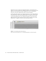
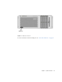
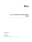
Locating Front Panel Features
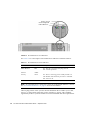
The illustration below shows the system features that you can access from the front
panel.
Status Indicators/control panel
USB ports
FIGURE 1-1
SAS disk drives (8)
Removable media drive
Front Panel Features
For information about front panel controls and indicators, see “Front Panel
Indicators” on page 10.
The system is configured with up to eight disk drives, which are accessible from the
front of the system.
Front Panel Indicators
Several front panel indicators provide general system status, alert you to system
problems, and help you to determine the location of system faults.
During system startup, the indicators are toggled on and off to verify that each one
is working correctly. Indicators located on the front panel work in conjunction with
specific fault indicators. For example, a fault in the power supply subsystem
Chapter 1
System Overview
9
illuminates the power supply Service Required indicator on the affected power
supply, as well as the system Service Required indicator. Since all front panel status
indicators are powered by the system’s standby power source, fault indicators
remain lit for any fault condition that results in a system shutdown.
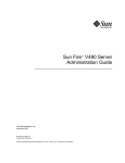
At the top left of the system as you look at its front are six system status indicators.
Power/OK indicator and the Service Required indicator provide a snapshot of the
overall system status. The Locator indicator helps you to quickly locate a specific
system even though it may be one of numerous systems in a room. The Locator
indicator/button is at the far left in the cluster, and is lit remotely by the system
administrator, or toggled on and off locally by pressing the button.
FIGURE 1-2
Front Panel System Status Indicators
Each system status indicator has a corresponding indicator on the back panel.
10
Sun Fire V445 Server Administration Guide • September 2007
Listed from left to right, the system status indicators operate as described in the
following table.
TABLE 1-2
Icon
System Status Indicators
Name
Description
Locator
This white indicator is lit by a Solaris command, Sun
Management Center command, or ALOM commands to help
you locate the system. There is also a Locator indicator button
that allows you to reset the Locator indicator. For information
on controlling the Locator indicator, see “Controlling the
Locator Indicator” on page 108.
Service Required This amber indicator lights steadily when a system fault is
detected. For example, the system Service Required indicator
lights when a fault occurs in a power supply or disk drive.
In addition to the system Service Required indicator, other
fault indicators might also be lit, depending on the nature of
the fault. If the system Service Required indicator is lit,
check the status of other fault indicators on the front panel
and other FRUs to determine the nature of the fault. See
Chapter 8 and Chapter 9.
System Activity
This green indicator blinks slowly then quickly during
startup. The Power/OK indicator lights continuosly when the
system power is on and the Solaris Operating System is
loaded and running.
TABLE 1-3 lists additional fault indicators, and describes the type of service required.
TABLE 1-3
Icon
System Diagnostic Indicators
Name
Location
Fan Tray Fault
This indicator indicates a fault in a fan tray. Additional
indicators on the top panel indicate which fan tray requires
service.
Power Supply
Fault
The indicator indicates a fault in a power supply. Look at
the individual power supply status indicators (on the back
panel) to determine which power supply requires service.
CPU
Overtemperature
This indicator indicates that a CPU has detected an
overtemperature condition. Look for any fan failures, as
well as a local overtemperature condition around the server.
For hard disk drive indicator descriptions, see TABLE 4-4. For fan tray indicator
descriptions located on the top panel of the server, see TABLE 4-6.
Chapter 1
System Overview
11
Power Button
The system Power button is recessed to prevent accidentally turning the system on
or off. If the operating system is running, pressing and releasing the Power button
initiates a graceful software system shutdown. Pressing and holding down the
Power button for four seconds causes an immediate hardware shutdown.
Caution – Whenever possible, use the graceful shutdown method. Forcing an
immediate hardware shutdown can cause disk drive corruption and loss of data.
Power button
FIGURE 1-3
Power Button Location
USB Ports
The Sun Fire V445 server has four Universal Serial Bus (USB) ports: two on the front
panel, and two on the back panel. All four USB ports comply with the USB 2.0
specification.
12
Sun Fire V445 Server Administration Guide • September 2007
USB ports
FIGURE 1-4
USB Ports Location
For more information about the USB ports, see “About the USB Ports” on page 95.
Chapter 1
System Overview
13
SAS Disk Drives
The system has up to eight hot-pluggable internal SAS disk drives.
SAS disk drives (8)
FIGURE 1-5
Hard Disk Drives Location
For more information about how to configure internal disk drives, see the “About
the Internal Disk Drives” on page 87.
Removable Media Drive
The Sun Fire V445 server has a DVD-ROM drive in a removable media bay. This
drive also has DVD-RW and CD-RW capabilities.
14
Sun Fire V445 Server Administration Guide • September 2007
Removable media drive
FIGURE 1-6
Removable Media Drive Location
For more information about servicing the DVD-ROM drive, see the Sun Fire V445
Server Service Manual.
Chapter 1
System Overview
15
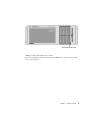
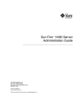
Locating Back Panel Features
The illustration below shows the system features that are accessible from the back
panel.
Power
supplies
PCIe card slots
PCI-X card slots
External
ports
16
Sun Fire V445 Server Administration Guide • September 2007
System status
indicators
FIGURE 1-7
Back Panel Features
Back Panel Indicators
The back panel system status indicators consist of the Locator indicator, Service
Required indicator, and the System Activity indicator. These indicators are located in
the bottom center of the back panel, and operate as described in TABLE 1-2.
Back panel system status indicators
For power supply indicator descriptions, see TABLE 4-5. For fan tray indicator
descriptions located on the top panel of the server, see TABLE 4-6.
Power Supplies
There are four AC/DC redundant (N+N) and hot-swappable power supplies, where
two power supplies are sufficient to power a fully configured system.
For more information about power supplies, see the following sections in the Sun
Fire V445 Server Service Manual:
■
■
■
■
“About Hot-Pluggable Components”
“Removing a Power Supply”
“Installing a Power Supply”
“Reference for Power Supply Status LEDs”
For more information about power supplies, see “About the Power Supplies” on
page 89.
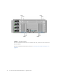
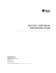
PCI Slots
The Sun Fire V445 server has four PCIe slots and four PCI-X slots. (One of the PCI-X
slots is occupied by the LSI Logic 1068X SAS controller.) These are labeled on the
back panel.
Chapter 1
System Overview
17
PCI0
PCI1
PCI3
PCI2
FIGURE 1-8
PCI6
PCI7
PCI5
PCI4
PCI Slot Locations
For more information about how to install a PCI card, see the Sun Fire V445 Server
Service Manual.
For more information about PCI cards, see “About the PCI Cards and Buses” on
page 81.
18
Sun Fire V445 Server Administration Guide • September 2007
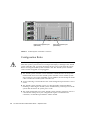
System Controller Ports
There are two system controller ports. Both use an RJ-45 connector.
Network management port
(NET MGT)
FIGURE 1-9
Serial management port
(SER MGT)
Network and Serial Management Port Locations
Network Management Port
This port provides direct network access to the ALOM system controller, when
configured, and can access the ALOM prompt and system console output.
Note – The system controller is accessed through the serial management port by
default. You must reconfigure the system controller to use the network management
port. See “Activating the Network Management Port” on page 42.
The network management port has a Link indicator that operates as described in
TABLE 1-4.
TABLE 1-4
Network Management Port Indicator
Name
Description
Link
This green indicator is lit when an Ethernet connection is
present.
Chapter 1
System Overview
19
Serial Management Port
The serial management port provides the default connection to the system controller
and can access the ALOM prompt and system console output. You can connect to the
serial management port using a VT100 terminal, a tip connection, or a terminal
server.
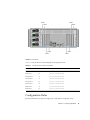
System I/O Ports
DB9 serial port (TTYB)
USB ports:
(USB0
USB1)
Gigabit Ethernet ports
FIGURE 1-10
System I/O Port Locations
USB Ports
There are two USB ports on the back panel. These comply with the USB 2.0
specification.
For more information about the USB ports, see “About the USB Ports” on page 95.
Gigabit Ethernet Ports
The Sun Fire V445 server has four Gigabit Ethernet ports.
20
Sun Fire V445 Server Administration Guide • September 2007
NET2
NET0
FIGURE 1-11
NET3
NET1
Gigabit Ethernet Port Locations
Each Gigabit Ethernet port has a corresponding status indicator, described in
TABLE 1-5.
TABLE 1-5
Ethernet Indicators
Color
Description
(None)
No connection present.
Green
This indicates a 10/100 Megabit Ethernet connection. The
indicator blinks to indicate network activity.
Amber
This indicates a Gigabit Ethernet connection. The indicator
blinks to indicate network activity.
DB-9 Serial Port
There is a POSIX compliant DB-9 serial port labeled TTYB. In addition, you may
configure the RJ-45 serial management port as a conventional serial port. See “About
the Serial Ports” on page 96.
Chapter 1
System Overview
21
Reliability, Availability, and
Serviceability (RAS) Features
The Sun Fire V445 server provides the following RAS features:
■
Hot-pluggable disk drives
■
Redundant, hot-swappable power supplies, fan trays, and USB components
■
Sun ALOM system controller with SSH connections for all remote monitoring and
control
■
Environmental monitoring
■
Automatic system restoration (ASR) capabilities for PCI cards and memory
DIMMs
■
Hardware watchdog mechanism and externally initiated reset (XIR) capability
■
Internal hardware disk mirroring (RAID 0/1)
■
Support for disk and network multipathing with automatic failover
■
Error correction and parity checking for improved data integrity
■
Easy access to all internal replaceable components
■
Full in-rack serviceability for all components
■
Persistent storage for all configuration change events
■
Persistent storage for all system console output
See Chapter 5 for information on how to configure these features.
Sun Cluster Software
Sun Cluster software enables you to connect up to eight Sun servers in a cluster
configuration. A cluster is a group of nodes that are interconnected to work as a
single, highly available and scalable system. A node is a single instance of Solaris
software. The software can be running on a standalone server or on a domain within
a standalone server. With Sun Cluster software, you can add or remove nodes while
online, and mix and match servers to meet your specific needs.
Sun Cluster software delivers high availability through automatic fault detection
and recovery, and scalability, ensuring that mission-critical applications and services
are always available when needed.
22
Sun Fire V445 Server Administration Guide • September 2007
With Sun Cluster software installed, other nodes in the cluster will automatically
take over and assume the workload when a node goes down. The software delivers
predictability and fast recovery capabilities through features such as local
application restart, individual application failover, and local network adapter
failover. Sun Cluster software significantly reduces downtime and increases
productivity by helping to ensure continuous service to all users.
The software lets you run both standard and parallel applications on the same
cluster. It supports the dynamic addition or removal of nodes, and enables Sun
servers and storage products to be clustered together in a variety of configurations.
Existing resources are used more efficiently, resulting in additional cost savings.
Sun Cluster software allows nodes to be separated by up to 10 kilometers. This way,
in the event of a disaster in one location, all mission-critical data and services remain
available from the other unaffected locations.
For more information, see the documentation supplied with the Sun Cluster
software.
Sun Management Center Software
Sun Management Center software is an open, extensible system monitoring and
management tool. The software is written in Java and uses Simple Network
Management Protocol (SNMP) to provide enterprise-wide monitoring of Sun servers
and workstations, including their subsystems, components, and peripheral devices.
For more information, see “About Sun Management Center” on page 218.
Chapter 1
System Overview
23
24
Sun Fire V445 Server Administration Guide • September 2007
CHAPTER
2
Configuring the System Console
This chapter explains what the system console is, describes the different ways of
configuring it on a Sun Fire V445 server, and helps you understand its relation to the
system controller.
Tasks covered in this chapter include:
■
■
■
■
■
■
■
■
■
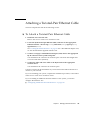
“Entering the ok Prompt” on page 40
“Using the Serial Management Port” on page 41
“Activating the Network Management Port” on page 42
“Accessing the System Console With a Terminal Server” on page 44
“Accessing the System Console With a Tip Connection” on page 47
“Modifying the /etc/remote File” on page 51
“Accessing the System Console With an Alphanumeric Terminal” on page 53
“To Verify Serial Port Settings on TTYB” on page 55
“Accessing the System Console With a Local Graphics Monitor” on page 56
Other information in this chapter includes:
■
■
■
■
■
“About Communicating With the System” on page 26
“About the sc> Prompt” on page 32
“About the ok Prompt” on page 35
“About Switching Between the ALOM System Controller and the System
Console” on page 38
“Reference for System Console OpenBoot Configuration Variable Settings” on
page 59
25
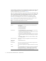
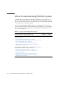
About Communicating With the System
To install your system software or to diagnose problems, you need some way to
interact at a low level with the system. The system console is Sun’s facility for doing
this. You use the system console to view messages and issue commands. There can
be only one system console per computer.
The serial management port (SERIAL MGT) is the default port for accessing the
system console upon initial system installation. After installation, you can configure
the system console to accept input from and send output to different devices. See
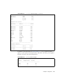
TABLE 2-1 for a summary.
TABLE 2-1
Ways of Communicating With the System
Devices Available for Accessing the System Console
After
Installation
A terminal server attached to the serial management port (SERIAL ✓
MGT) or TTYB. See:
• “Using the Serial Management Port” on page 41
• “To Access the System Console With a Terminal Server Through
the Serial Management Port” on page 44
• “To Verify Serial Port Settings on TTYB” on page 55
• “Reference for System Console OpenBoot Configuration
Variable Settings” on page 59
✓
✓
✓
An alphanumeric terminal or similar device attached to the serial
management port (SERIAL MGT) or TTYB. See:
• “Using the Serial Management Port” on page 41
• “Accessing the System Console With an Alphanumeric
Terminal” on page 53
• “To Verify Serial Port Settings on TTYB” on page 55
• “Reference for System Console OpenBoot Configuration
Variable Settings” on page 59
26
During
Installation*
Sun Fire V445 Server Administration Guide • September 2007
TABLE 2-1
Ways of Communicating With the System (Continued)
During
Installation*
Devices Available for Accessing the System Console
After
Installation
A tip line attached to the serial management port (SERIAL MGT) ✓
or TTYB. See:
• “Using the Serial Management Port” on page 41
• “Accessing the System Console With a Tip Connection” on
page 47
• “Modifying the /etc/remote File” on page 51
• “To Verify Serial Port Settings on TTYB” on page 55
• “Reference for System Console OpenBoot Configuration
Variable Settings” on page 59
✓
An Ethernet line connected to the network management port
(NET MGT). See:
• “Activating the Network Management Port” on page 42
✓
A local graphics monitor (frame buffer card, graphics monitor,
mouse, and so forth). See:
• “To Access the System Console With a Local Graphics Monitor”
on page 56
• “Reference for System Console OpenBoot Configuration
Variable Settings” on page 59
✓
* After initial system installation, you can redirect the system console to take its input from and send its output to
the serial port TTYB.
About Using the System Console
The system console device can be either a standard alphanumeric terminal, terminal
server, Tip connection from another Sun system, or a local graphics monitor. The
default connection is through the serial management port (labeled SERIAL MGT) on
the chassis back panel. You can also connect an alphanumeric terminal to the serial
(DB-9) connector (as TTYB) on the system back panel. A local graphics monitor
requires installation of a PCI graphics card, monitor, USB keyboard, and mouse. You
can also access the system console through a network connection with the network
management port.
The system console displays status and error messages generated by firmware-based
tests during system startup. After those tests have been run, you can enter special
commands that affect the firmware and alter system behavior. For more information
about tests that run during the boot process, see Chapter 8 and Chapter 9.
Chapter 2
Configuring the System Console
27
Once the OS is booted, the system console displays UNIX system messages and
accepts UNIX commands.
To use the system console, you need some means of getting data in to and out of the
system, which means attaching some kind of hardware to the system. Initially, you
might have to configure that hardware, and load and configure appropriate software
as well.
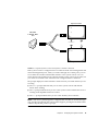
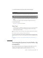
You also must ensure that the system console is directed to the appropriate port on
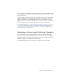
the Sun Fire V445 server’s back panel – generally, the one to which your hardware
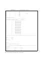
console device is attached. (See FIGURE 2-1.) You do this by setting the inputdevice and output-device OpenBoot configuration variables.
Sun Fire V445 Server
Ports
Console Devices
SERIAL MGT
tip
Line
OpenBoot Config. Variable Settings
input-device=ttya
output-device=ttya
NET MGT
Alphanumeric
Terminal
input-device=ttyb
System
Console
output-device=ttyb
Terminal
Server
ttyb
input-device=keyboard
output-device=screen
FIGURE 2-1
Graphics Card
Graphics
Monitor
Directing the System Console to Different Ports and Different Devices
The following subsections provide background information and references to
instructions appropriate for the particular device you choose to access the system
console. For instructions on attaching and configuring a device to access the system
console, see:
■
■
■
■
28
“Using the Serial Management Port” on page 41
“Activating the Network Management Port” on page 42
“Accessing the System Console With a Terminal Server” on page 44
“Accessing the System Console With a Tip Connection” on page 47
Sun Fire V445 Server Administration Guide • September 2007
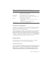
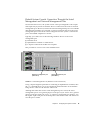
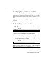
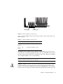
Default System Console Connection Through the Serial
Management and Network Management Ports
On Sun Fire V445 servers, the system console comes preconfigured to allow input
and output only by means of hardware devices connected to the serial or network
management ports. However, because the network management port is not available
until network parameters are assigned, your first connection must be to the serial
management port. The network can be configured once the system is connected to
power and ALOM completes its self test.
Typically, you connect one of the following hardware devices to the serial
management port:
■
■
■
Terminal server
Alphanumeric terminal or similar device
A Tip line connected to another Sun computer
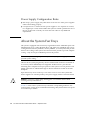
This provides for secure access at the installation site.
Network management port
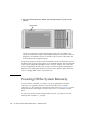
(NET MGT)
FIGURE 2-2
Serial management port
(SER MGT)
Serial Management Port (Default Console Connection)
Using a Tip line might be preferable to connecting an alphanumeric terminal, since
the tip command allows you to use windowing and OS features on the machine
being used to connect to the Sun Fire V445 server.
Although the Solaris OS sees the serial management port as TTYA, the serial
management port is not a general-purpose serial port. If you want to use a generalpurpose serial port with your server – to connect a serial printer, for instance – use
the regular 9-pin serial port on the back panel of the Sun Fire V445. The Solaris OS
sees this port as TTYB.
Chapter 2
Configuring the System Console
29
For instructions on accessing the system console through a terminal server, see
“Accessing the System Console With a Terminal Server” on page 44.
For instructions on accessing the system console through an alphanumeric terminal,
see “Accessing the System Console With an Alphanumeric Terminal” on page 53.
For instructions on accessing the system console with a Tip line, see “To Access the
System Console With a Tip Connection Throught the Serial Management Port” on
page 48.
Access Through the Network Management Port
Once you have configured the network management port, you can connect an
Ethernet-capable device to the system console through your network. This
connection provides for remote monitoring and control. In addition, up to four
simultaneous connections to the system controller sc> prompt are available through
the network management port. For more information, see “Activating the Network
Management Port” on page 42.
For more information about the system console and the ALOM system controller,
see:
■
■
“About the sc> Prompt” on page 32
“About the ok Prompt” on page 35
ALOM
ALOM software is preinstalled on the server’s system controller (SC) and is enabled
at the first power on. ALOM provides remote powering on and off, diagnostics
capabilities, environmental control, and monitoring operations for the server. The
primary functions of ALOM include the following:
■
■
■
■
■
■
■
Operation of system indicators
Fan speed monitoring and adjustment
Temperature monitoring and alerts
Power supply health monitoring and control
USB overcurrent monitoring and alerts
Hot-plug configuration change monitoring and alerts
Dynamic FRU ID data transactions
For more information about ALOM software, see “About the ALOM System
Controller Card” on page 77.
30
Sun Fire V445 Server Administration Guide • September 2007
Alternative System Console Configuration
In the default configuration, system controller alerts and system console output
appear interspersed in the same window. After initial system installation, you can
redirect the system console to take its input from and send its output to the serial
port TTYB, or to a graphics card’s port.
A serial port and the PCI slots are located on the rear panel. Two USB ports are
located on the front panel.
The chief advantage of redirecting the system console to another port is that it
allows you to divide system controller alerts and system console output into two
separate windows.
However, there are some serious disadvantages to alternative console configuration:
■
POST output can only be directed to the serial management and network
management ports. It cannot be directed to TTYB or to a graphics card’s port.
■
If you have directed the system console to TTYB, you cannot use this port for any
other serial device.
■
In a default configuration, the serial management and network management ports
enable you to open up to four additional windows by which you can view, but
not affect, system console activity. You cannot open these windows if the system
console is redirected to TTYB or to a graphics card’s port.
■
In a default configuration, the serial management and network management ports
enable you to switch between viewing system console and system controller
output on the same device by typing a simple escape sequence or command. The
escape sequence and commands do not work if the system console is redirected to
TTYB or to a graphics card’s port.
■
The system controller keeps a log of console messages, but some messages are not
logged if the system console is redirected to TTYB or to a graphic card’s port. The
omitted information could be important if you need to contact Sun customer
service with a problem.
For all the preceding reasons, the best practice is to leave the system console in its
default configuration.
You change the system console configuration by setting OpenBoot configuration
variables. See “Reference for System Console OpenBoot Configuration Variable
Settings” on page 59.
You can also set OpenBoot configuration variables using the ALOM system
controller. For details, see the Sun Advanced Lights Out Manager (ALOM) Online Help.
Chapter 2
Configuring the System Console
31
Accessing the System Console Through a Graphics Monitor
The Sun Fire V445 server is shipped without a mouse, keyboard, monitor, or frame
buffer for the display of bitmapped graphics. To install a graphics monitor on the
server, you must install a frame buffer card into a PCI slot, and attach a monitor,
mouse, and keyboard to the appropriate back panel ports.
After starting the system, you might need to install the correct software driver for
the PCI card you have installed. For detailed hardware instructions, see “To Access
the System Console With a Local Graphics Monitor” on page 56.
Note – Power-on self-test (POST) diagnostics cannot display status and error
messages to a local graphics monitor.
About the sc> Prompt
The ALOM system controller runs independently of the Sun Fire V445 server and
regardless of system power state. When you connect a Sun Fire V445 server to AC
power, the ALOM system controller immediately starts up, and begins monitoring
the system.
Note – To view ALOM system controller boot messages, you must connect an
alphanumeric terminal to the serial management port before connecting the AC
power cords to the Sun Fire V445 server.
You can log in to the ALOM system controller at any time, regardless of system
power state, as long as AC power is connected to the system and you have a way of
interacting with the system. You can also access the ALOM system controller prompt
(sc>) from the ok prompt or from the Solaris prompt, provided the system console
is configured to be accessible through the serial management and network
management ports. For more information, see:
■
“Entering the ok Prompt” on page 40
■
“About Switching Between the ALOM System Controller and the System
Console” on page 38
The sc> prompt indicates that you are interacting with the ALOM system controller
directly. It is the first prompt you see when you log in to the system through the
serial management port or network management port, regardless of system power
state.
32
Sun Fire V445 Server Administration Guide • September 2007
Note – When you access the ALOM system controller for the first time, it forces you
to create a user name and password for subsequent access. After this initial
configuration, you will be prompted to enter a user name and password every time
you access the ALOM system controller.
Chapter 2
Configuring the System Console
33
Access Through Multiple Controller Sessions
Up to five ALOM system controller sessions can be active concurrently, one session
through the serial management port and up to four sessions through the network
management port.
Users of each of these sessions can issue commands at the sc> prompt, but only one
user session can have write-access to the system console at anytime. The other
sessions accessing the system console will have read-only capability.
For more information, see:
■
■
“Using the Serial Management Port” on page 41
“Activating the Network Management Port” on page 42.
Any additional ALOM system controller sessions afford passive views of system
console activity, until the active user of the system console logs out. However, the
console -f command, if you enable it, allows users to seize access to the system
console from one another. For more information, see the Sun Advanced Lights Out
Manager (ALOM) Online Help.
Ways of Reaching the sc> Prompt
There are several ways to get to the sc> prompt. These are:
■
If the system console is directed to the serial management and network
management ports, you can type the ALOM system controller escape sequence
(#.).
Note – #. (pound period) is the default setting for the escape sequence to enter
ALOM. It is a configurable variable.
34
■
You can log in directly to the ALOM system controller from a device connected to
the serial management port. See “Using the Serial Management Port” on page 41.
■
You can log in directly to the ALOM system controller using a connection through
the network management port. See “Activating the Network Management Port”
on page 42.
Sun Fire V445 Server Administration Guide • September 2007
About the ok Prompt
A Sun Fire V445 server with the Solaris OS installed is capable of operating at
different run levels. A synopsis of run levels follows. For a full description, see the
Solaris system administration documentation.
Most of the time, you operate a Sun Fire V445 server at run level 2 or run level 3,
which are multiuser states with access to full system and network resources.
Occasionally, you might operate the system at run level 1, which is a single-user
administrative state. However, the lowest operational state is run level 0. At this
state, it is safe to turn off power to the system.
When a Sun Fire V445 server is at run level 0, the ok prompt appears. This prompt
indicates that the OpenBoot firmware is in control of the system.
There are a number of scenarios in which OpenBoot firmware control can happen.
■
By default, the system powers up to OpenBoot firmware control before the OS is
installed.
■
The system boots to the ok prompt when the auto-boot? OpenBoot
configuration variable is set to false.
■
The system transitions to run level 0 in an orderly way when the OS is halted.
■
The system reverts to OpenBoot firmware control when the OS crashes.
■
When a serious hardware problem develops while the system is running, the OS
transitions smoothly to run level 0.
■
You deliberately place the server under firmware control in order to execute
firmware-based commands or to run diagnostic tests.
It is the last of these scenarios that most often concerns you as an administrator,
since there will be times when you need to reach the ok prompt. The several ways to
do this are outlined in “Entering the ok Prompt” on page 35. For detailed
instructions, see “Entering the ok Prompt” on page 40.
Entering the ok Prompt
There are several ways to enter the ok prompt, depending on the state of the system
and the means by which you are accessing the system console. In order of
desirability, these are:
■
■
■
■
Graceful shutdown
ALOM system controller break or console command
L1-A (Stop-A) keys or Break key
Externally initiated reset (XIR)
Chapter 2
Configuring the System Console
35
■
Manual system reset
A description of each method follows. For instructions, see “Entering the ok
Prompt” on page 40.
Graceful Shutdown
The preferred method of reaching the ok prompt is to shut down the OS by issuing
an appropriate command (for example, the shutdown, init, or uadmin command)
as described in Solaris system administration documentation. You can also use the
system Power button to initiate a graceful system shutdown.
Gracefully shutting down the system prevents data loss, enables you to warn users
beforehand, and causes minimal disruption. You can usually perform a graceful
shutdown, provided the Solaris OS is running and the hardware has not experienced
serious failure.
You can also perform a graceful system shutdown from the ALOM system controller
command prompt.
For more information, see:
■
■
“Powering Off the Server Locally” on page 66
“Powering Off the System Remotely” on page 64
ALOM System Controller break or console Command
Typing break from the sc> prompt forces a running Sun Fire V445 server to move
to OpenBoot firmware control. If the OS is already halted, you can use the console
command instead of break to reach the ok prompt.
If you issue a break at the SC you will remain in an SC prompt. To use the OpenBoot
prompt, enter the console command. For example:
TABLE 2-2
hostname> #. [characters are not echoed to the screen]
sc> break -y [break on its own will generate a confirmation prompt]
sc> console
ok
After forcing the system into OpenBoot firmware control, be aware that issuing
certain OpenBoot commands (like probe-scsi, probe-scsi-all, or probe-ide)
might hang the system.
36
Sun Fire V445 Server Administration Guide • September 2007
L1-A (Stop-A) Keys or Break Key
When it is impossible or impractical to shut down the system gracefully, you can get
to the ok prompt by typing the L1-A (Stop-A) key sequence from a Sun keyboard, or,
if you have an alphanumeric terminal attached to the Sun Fire V445 server, by
pressing the Break key.
After forcing the system into OpenBoot firmware control, be aware that issuing
certain OpenBoot commands (like probe-scsi, probe-scsi-all, or probe-ide)
might hang the system.
Note – These methods of reaching the ok prompt will only work if the system
console has been redirected to the appropriate port. For details, see “Reference for
System Console OpenBoot Configuration Variable Settings” on page 59
Externally Initiated Reset (XIR)
Use the ALOM system controller reset -x command to execute an externally
initiated reset (XIR). Forcing an XIR might be effective in breaking the deadlock that
is hanging up the system. However, an XIR also precludes the orderly shutdown of
applications, and so it is not the preferred method of reaching the ok prompt, unless
you are troubleshooting these types of system hangs. Generating an XIR has the
advantage of allowing you to issue the sync command to produce a dump file of the
current system state for diagnostic purposes.
For more information, see:
■
■
Chapter 8 and Chapter 9
Sun Advanced Lights Out Manager (ALOM) Online Help
Caution – Because an XIR precludes an orderly shutdown of applications, it should
only be attempted if previously described methods do not work.
Manual System Reset
Use the ALOM system controller reset command, or poweron and poweroff
commands, to reset the server. Reaching the ok prompt by performing a manual
system reset or by power-cycling the system should be the method of last resort.
Doing this results in the loss of all system coherence and state information. A
manual system reset could corrupt the server’s file systems, although the fsck
command usually restores them.
Chapter 2
Configuring the System Console
37
Caution – Forcing a manual system reset results in loss of system state data, and
should be attempted only as a last resort. After a manual system reset, all state
information is lost, which inhibits troubleshooting the cause of the problem until the
problem reoccurs.
Caution – When you access the ok prompt from a functioning Sun Fire V445 server,
you are suspending the Solaris OS and placing the system under firmware control.
Any processes that were running under the OS are also suspended, and the state of
such processes might not be recoverable.
The commands you run from the ok prompt have the potential to affect the state of
the system. This means that it is not always possible to resume execution of the OS
from the point at which it was suspended. The diagnostic tests you run from the ok
prompt will affect the state of the system. This means that it is not possible to
resume execution of the OS from the point at which it was suspended.
Although the go command will resume execution in most circumstances, in general,
each time you force the system down to the ok prompt, you should expect to have to
reboot the system to get back to the OS.
As a rule, before suspending the OS, you should back up files, warn users of the
impending shutdown, and halt the system in an orderly manner. However, it is not
always possible to take such precautions, especially if the system is malfunctioning.
For more information about the OpenBoot firmware, see the OpenBoot 4.x Command
Reference Manual. An online version of the manual is included with the OpenBoot
Collection AnswerBook that ships with Solaris software.
About Switching Between the ALOM
System Controller and the System
Console
The Sun Fire V445 server features two management ports, labeled SERIAL MGT and
NET MGT, located on the server’s back panel. If the system console is directed to use
the serial management and network management ports (its default configuration),
these ports provide access to both the system console and the ALOM system
controller, each on separate channels (FIGURE 2-3).
38
Sun Fire V445 Server Administration Guide • September 2007
System Console
ok
#
NET MGT
or SERIAL MGT
Port
console
#.
sc>
ALOM System Controller
FIGURE 2-3
Separate System Console and System Controller Channels
If the system console is configured to be accessible from the serial management and
network management ports, when you connect through one of these ports you can
access either the ALOM command-line interface or the system console. You can
switch between the ALOM system controller and the system console at any time, but
you cannot access both at the same time from a single terminal or shell tool.
The prompt displayed on the terminal or shell tool tells you which channel you are
accessing:
■
The # or % prompt indicates that you are at the system console and that the
Solaris OS is running.
■
The ok prompt indicates that you are at the system console and that the server is
running under OpenBoot firmware control.
■
The sc> prompt indicates that you are at the ALOM system controller.
Note – If no text or prompt appears, it might be the case that no console messages
were recently generated by the system. If this happens, pressing the terminal’s Enter
or Return key should produce a prompt.
Chapter 2
Configuring the System Console
39
To reach the system console from the ALOM system controller, type the console
command at the sc> prompt. To reach the ALOM system controller from the system
console, type the system controller escape sequence, which by default is #. (pound
period).
For more information, see:
■
■
■
■
■
“About Communicating With the System” on page 26
“About the sc> Prompt” on page 32
“About the ok Prompt” on page 35
“Using the Serial Management Port” on page 41
Sun Advanced Lights Out Manager (ALOM) Online Help
Entering the ok Prompt
This procedure provides several ways of reaching the ok prompt. The methods are
not equally desirable. For details about when to use each method, see “About the ok
Prompt” on page 35.
Caution – Dropping the Sun Fire V445 server to the ok prompt suspends all
application and OS software. After you issue firmware commands and run
firmware-based tests from the ok prompt, the system might not be able to resume
where it left off.
▼
To Enter the ok Prompt
1. If at all possible, back up system data before starting this procedure.
For information about the appropriate backup and shutdown procedures, refer to
Solaris system administration documentation.
2. Exit or stop all applications and warn users of the impending loss of service.
3. Decide which method you need to use to reach the ok prompt.
See “About the ok Prompt” on page 35 for details.
40
Sun Fire V445 Server Administration Guide • September 2007
4. Refer to TABLE 2-3 for instructions.
TABLE 2-3
Ways of Accessing the ok Prompt
Access Method
What to Do
Graceful shutdown of
the Solaris OS
• From a shell or command tool window, issue an appropriate
command (for example, the shutdown or init command) as
described in Solaris system administration documentation.
L1-A (Stop-A) keys or
Break key
• From a Sun keyboard connected directly to the Sun Fire V445
server, press the Stop and A keys simultaneously.*
–or–
• From an alphanumeric terminal configured to access the system
console, press the Break key.
ALOM system
controller console or
break command
• From the sc> prompt, type the break command. The console
command also works, provided the OS software is not running
and the server is already under OpenBoot firmware control.
Externally initiated
reset (XIR)
• From the sc> prompt, type the reset -x command.
Manual system reset
• From the sc> prompt, type the reset command.
* Requires the OpenBoot configuration variable input-device=keyboard. For more information, see “Accessing the System Console With a Local Graphics Monitor” on page 56 and “Reference for System Console
OpenBoot Configuration Variable Settings” on page 59.
Using the Serial Management Port
This procedure assumes that the system console is directed to use the serial
management and network management ports (the default configuration).
When you are accessing the system console using a device connected to the serial
management port, your first point of access is the ALOM system controller and its
sc> prompt. After connecting to the ALOM system controller, you can switch to the
system console itself.
For more information about the ALOM system controller card, see:
■
■
“About the ALOM System Controller Card” on page 77
Sun Advanced Lights Out Manager (ALOM) Online Help
Ensure that the serial port on your connecting device is set to the following
parameters:
■
■
■
9600 baud
8 bits
No parity
Chapter 2
Configuring the System Console
41
■
■
▼
1 stop bit
No handshaking
To Use the Serial Management Port
1. Establish an ALOM system controller session.
See Sun Advanced Lights Out Manager (ALOM) Online Help for instructions.
2. To connect to the system console, at the ALOM system controller command
prompt, type:
sc> console
The console command switches you to the system console.
3. To switch back to the sc> prompt, type the #. escape sequence.
TABLE 2-4
ok #. [characters are not echoed to the screen]
For instructions on how to use the ALOM system controller, see:
■
Sun Advanced Lights Out Manager (ALOM) Online Help
Activating the Network Management
Port
You must assign an Internet Protocol (IP) address to the network management port
before you can use it. If you are configuring the network management port for the
first time, you must first connect to the ALOM system controller using the serial
management port and assign an IP address to the network management port. You
can either assign an IP address manually, or you can configure the port to obtain an
IP address using the Dynamic Host Configuration Protocol (DHCP) from another
server.
Data centers frequently devote a separate subnet to system management. If your
data center has such a configuration, connect the network management port to this
subnet.
42
Sun Fire V445 Server Administration Guide • September 2007
Note – The network management port is a 10BASE-T port. The IP address assigned
to the network management port is a unique IP address, separate from the main Sun
Fire V445 server IP address, and is dedicated for use only with the ALOM system
controller. For more information, see “About the ALOM System Controller Card” on
page 77.
▼
To Activate the Network Management Port
1. Connect an Ethernet cable to the network management port.
2. Log in to the ALOM system controller through the serial management port.
For more information about connecting to the serial management port, see
“Using the Serial Management Port” on page 41.
3. Assign IP addresses by typing one of the following commands:
■
If your network uses static IP addresses, type:
TABLE 2-5
sc>
sc>
sc>
sc>
setsc
setsc
setsc
setsc
if_network true
netsc_ipaddr ip-address
netsc_ipnetmask ip-address
netsc_ipgateway ip-address
Note – The if_network command requires resetting the SC before the changes
take effect. Reset the SC with the resetsc command after changing network
parameters.
■
If your network uses Dynamic Host Configuration Protocol (DHCP), type:
TABLE 2-6
sc> setsc netsc_dhcp
4. Select the communications protocol, either Telnet, SSH, or none, type:
TABLE 2-7
sc> setsc if_connection none|ssh|telnet
Note – none is the default.
Chapter 2
Configuring the System Console
43
5. To verify the network settings, type:
TABLE 2-8
sc> shownetwork
6. Log out of the ALOM system controller session.
To connect through the network management port, use the telnet command to the
IP address you specified in Step 3 of the preceding procedure.
Accessing the System Console With a
Terminal Server
The following procedure assumes that you are accessing the system console by
connecting a terminal server to the serial management port (SERIAL MGT) of the
Sun Fire V445 server.
▼
To Access the System Console With a Terminal
Server Through the Serial Management Port
1. Complete the physical connection from the serial management port to your
terminal server.
The serial management port on the Sun Fire V445 server is a data terminal
equipment (DTE) port. The pinouts for the serial management port correspond with
the pinouts for the RJ-45 ports on the Serial Interface Breakout Cable supplied by
Cisco for use with the Cisco AS2511-RJ terminal server. If you use a terminal server
made by another manufacturer, check that the serial port pinouts of the Sun Fire
V445 server match those of the terminal server you plan to use.
If the pinouts for the server serial ports correspond with the pinouts for the RJ-45
ports on the terminal server, you have two connection options:
44
■
Connect a serial interface breakout cable directly to the Sun Fire V445 server. See
“Using the Serial Management Port” on page 41.
■
Connect a serial interface breakout cable to a patch panel and use the straightthrough patch cable (supplied by Sun) to connect the patch panel to the server.
Sun Fire V445 Server Administration Guide • September 2007
1
Terminal
server
3
2
4
5
6
7
8
9
10
11
12
13
14
15
Straight-through cable
1
2
3
4
5
6
7
8
9
10 11 12 13 14 15
Patch panel
Patch cable to serial management port
Sun Fire V445
server
FIGURE 2-4
Patch Panel Connection Between a Terminal Server and a Sun Fire V445
Server
If the pinouts for the serial management port do not correspond with the pinouts for
the RJ-45 ports on the terminal server, you need to make a crossover cable that takes
each pin on the Sun Fire V445 server serial management port to the corresponding
pin in the terminal server’s serial port.
TABLE 2-9 shows the crossovers that the cable must perform.
TABLE 2-9
Pin Crossovers for Connecting to a Typical Terminal Server
Sun Fire V445 Serial Port (RJ-45 Connector) Pin Terminal Server Serial Port Pin
Pin 1 (RTS)
Pin 1 (CTS)
Pin 2 (DTR)
Pin 2 (DSR)
Pin 3 (TXD)
Pin 3 (RXD)
Pin 4 (Signal Ground)
Pin 4 (Signal Ground)
Pin 5 (Signal Ground)
Pin 5 (Signal Ground)
Chapter 2
Configuring the System Console
45
TABLE 2-9
Pin Crossovers for Connecting to a Typical Terminal Server (Continued)
Sun Fire V445 Serial Port (RJ-45 Connector) Pin Terminal Server Serial Port Pin
Pin 6 (RXD)
Pin 6 (TXD)
Pin 7 (DSR /DCD)
Pin 7 (DTR)
Pin 8 (CTS)
Pin 8 (RTS)
2. Open a terminal session on the connecting device, and type:
TABLE 5
% telnet IP-address-of-terminal-server port-number
For example, for a Sun Fire V445 server connected to port 10000 on a terminal server
whose IP address is 192.20.30.10, you would type:
TABLE 6
% telnet 192.20.30.10 10000
▼
To Access the System Console With a Terminal
Server Through the TTYB Port
1. Redirect the system console by changing OpenBoot configuration variables.
At the ok prompt, type:
TABLE 2-10
ok setenv input-device ttyb
ok setenv output-device ttyb
Note – Redirecting the system console does not redirect POST output. You can only
view POST messages from the serial and network management port devices.
Note – There are many other OpenBoot configuration variables. Although these
variables do not affect which hardware device is used to access the system console,
some of them affect which diagnostic tests the system runs and which messages the
system displays at its console. See Chapter 8 and Chapter 9.
46
Sun Fire V445 Server Administration Guide • September 2007
2. To cause the changes to take effect, power off the system. Type:
ok power-off
The system permanently stores the parameter changes and powers off.
Note – You can also power off the system using the front panel Power button.
3. Connect the null modem serial cable to the TTYB port on the Sun Fire V445
server.
If required, use the DB-9 or DB-25 cable adapter supplied with the server.
4. Power on the system.
See Chapter 3 for power-on procedures.
What Next
Continue with your installation or diagnostic test session as appropriate. When
you are finished, end your session by typing the terminal server’s escape
sequence and exit the window.
For more information about connecting to and using the ALOM system controller,
see:
■
Sun Advanced Lights Out Manager (ALOM) Online Help
If you have redirected the system console to TTYB and want to change the system
console settings back to use the serial management and network management ports,
see:
■
“Reference for System Console OpenBoot Configuration Variable Settings” on
page 59
Accessing the System Console With a Tip
Connection
This procedure assumes that you are accessing the Sun Fire V445 server system
console by connecting the serial port of another Sun system to the serial
management port (SERIAL MGT) of the Sun Fire V445 server (FIGURE 2-7).
Chapter 2
Configuring the System Console
47
Serial management port
Serial port
Tip connection
FIGURE 2-7
▼
Another Sun system
Tip Connection Between a Sun Fire V445 Server and Another Sun System
To Access the System Console With a Tip
Connection Throught the Serial Management
Port
1. Connect the RJ-45 serial cable and, if required, the DB-9 or DB-25 adapter
provided.
The cable and adapter connect between another Sun system’s serial port
(typically TTYB) and the serial management port on the back panel of the Sun
Fire V445 server. Pinouts, part numbers, and other details about the serial cable
and adapter are provided in the Sun Fire V445 Server Parts Installation and Removal
Guide.
2. Ensure that the /etc/remote file on the Sun system contains an entry for
hardwire.
Most releases of Solaris OS software shipped since 1992 contain an /etc/remote
file with the appropriate hardwire entry. However, if the Sun system is running
an older version of Solaris OS software, or if the /etc/remote file has been
modified, you might need to edit it. See “Modifying the /etc/remote File” on
page 51 for details.
48
Sun Fire V445 Server Administration Guide • September 2007
3. In a shell tool window on the Sun system, type:
Table 2-11
% tip hardwire
The Sun system responds by displaying:
Table 2-12
connected
The shell tool is now a Tip window directed to the Sun Fire V445 server through
the Sun system’s serial port. This connection is established and maintained even
when the Sun Fire V445 server is completely powered off or just starting up.
Note – Use a shell tool or a CDE or JDS terminal (such as dtterm), not a command
tool. Some tip commands might not work properly in a command tool window.
▼
To Access the System Console With a Tip
Connection Through the TTYB Port
1. Redirect the system console by changing the OpenBoot configuration
variables.
At the ok prompt on the Sun Fire V445 server, type:
TABLE 2-13
ok setenv input-device ttyb
ok setenv output-device ttyb
Note – You can only access the sc> prompt and view POST messages from either
the serial management port or the network management port.
Note – There are many other OpenBoot configuration variables. Although these
variables do not affect which hardware device is used to access the system console,
some of them affect which diagnostic tests the system runs and which messages the
system displays at its console. See Chapter 8 and Chapter 9.
Chapter 2
Configuring the System Console
49
2. To cause the changes to take effect, power off the system. Type:
ok power-off
The system permanently stores the parameter changes and powers off.
Note – You can also power off the system using the front panel Power button.
3. Connect the null modem serial cable to the TTYB port on the Sun Fire V445
server.
If required, use the DB-9 or DB-25 cable adapter supplied with the server.
4. Power on the system.
See Chapter 3 for power-on procedures.
Continue with your installation or diagnostic test session as appropriate. When
you are finished using the tip window, end your Tip session by typing ~. (the
tilde symbol followed by a period) and exit the window. For more information
about tip commands, see the tip man page.
For more information about connecting to and using the ALOM system controller,
see:
■
Sun Advanced Lights Out Manager (ALOM) Online Help
If you have redirected the system console to TTYB and want to change the system
console settings back to use the serial management and network management ports,
see:
■
50
“Reference for System Console OpenBoot Configuration Variable Settings” on
page 59
Sun Fire V445 Server Administration Guide • September 2007
Modifying the /etc/remote File
This procedure might be necessary if you are accessing the Sun Fire V445 server
using a Tip connection from a Sun system running an older version of the Solaris OS
software. You might also need to perform this procedure if the /etc/remote file on
the Sun system has been altered and no longer contains an appropriate hardwire
entry.
This procedure assumes that you are logged in as superuser to the system console of
a Sun system that you intend to use to establish a tip connection to the Sun Fire
V445 server.
▼
To Modify the /etc/remote File
1. Determine the release level of Solaris OS software installed on the Sun
system. Type:
Table 2-14
# uname -r
The system responds with a release number.
2. Do one of the following, depending on the number displayed.
■
If the number displayed by the uname -r command is 5.0 or higher:
The Solaris software shipped with an appropriate entry for hardwire in the
/etc/remote file. If you have reason to suspect that this file was altered and
the hardwire entry modified or deleted, check the entry against the
following example, and edit it as needed.
Table 2-15
hardwire:\
:dv=/dev/term/b:br#9600:el=^C^S^Q^U^D:ie=%$:oe=^D:
Note – If you intend to use the Sun system’s serial port A rather than serial port B,
edit this entry by replacing /dev/term/b with /dev/term/a.
Chapter 2
Configuring the System Console
51
■
If the number displayed by the uname -r command is less than 5.0:
Check the /etc/remote file and add the following entry, if it does not
already exist.
Table 2-16
hardwire:\
:dv=/dev/ttyb:br#9600:el=^C^S^Q^U^D:ie=%$:oe=^D:
Note – If you intend to use the Sun system’s serial port A rather than serial port B,
edit this entry by replacing /dev/ttyb with /dev/ttya.
The /etc/remote file is now properly configured. Continue establishing a Tip
connection to the Sun Fire V445 server system console. See:
■
“Accessing the System Console With a Tip Connection” on page 47
If you have redirected the system console to TTYB and want to change the system
console settings back to use the serial management and network management ports,
see:
■
52
“Reference for System Console OpenBoot Configuration Variable Settings” on
page 59
Sun Fire V445 Server Administration Guide • September 2007
Accessing the System Console With an
Alphanumeric Terminal
This procedure assumes that you are accessing the Sun Fire V445 server system
console by connecting the serial port of an alphanumeric terminal to the serial
management port (SERIAL MGT) of the Sun Fire V445 server.
▼
To Access the System Console With an
Alphanumeric Terminal Through the Serial
Management Port
1. Attach one end of the serial cable to the alphanumeric terminal’s serial port.
Use a null modem serial cable or an RJ-45 serial cable and null modem adapter.
Plug this cable in to the terminal’s serial port connector.
2. Attach the opposite end of the serial cable to the serial management port on
the Sun Fire V445 server.
3. Connect the alphanumeric terminal’s power cord to an AC outlet.
4. Set the alphanumeric terminal to receive:
■
■
■
■
■
9600 baud
8 bits
No parity
1 stop bit
No handshake protocol
See the documentation accompanying your terminal for information about how to
configure it.
Chapter 2
Configuring the System Console
53
▼
To Access the System Console With an
Alphanumeric Terminal Through the TTYB Port
1. Redirect the system console by changing the OpenBoot configuration
variables.
At the ok prompt, type:
TABLE 2-17
ok setenv input-device ttyb
ok setenv output-device ttyb
Note – You can only access the sc> prompt and view POST messages from either
the serial management port or the network management port.
Note – There are many other OpenBoot configuration variables. Although these
variables do not affect which hardware device is used to access the system console,
some of them affect which diagnostic tests the system runs and which messages the
system displays at its console. See Chapter 8 and Chapter 9.
2. To cause the changes to take effect, power off the system. Type:
ok power-off
The system permanently stores the parameter changes and powers off.
Note – You can also power off the system using the front panel Power button.
3. Connect the null modem serial cable to the TTYB port on the Sun Fire V445
server.
If required, use the DB-9 or DB-25 cable adapter supplied with the server.
4. Power on the system.
See Chapter 3 for power-on procedures.
You can issue system commands and view system messages using the alphanumeric
terminal. Continue with your installation or diagnostic procedure, as needed. When
you are finished, type the alphanumeric terminal’s escape sequence.
54
Sun Fire V445 Server Administration Guide • September 2007
For more information about connecting to and using the ALOM system controller,
see:
■
Sun Advanced Lights Out Manager (ALOM) Online Help
If you have redirected the system console to TTYB and want to change the system
console settings back to use the serial management and network management ports,
see:
■
“Reference for System Console OpenBoot Configuration Variable Settings” on
page 59
Verifying Serial Port Settings on TTYB
This procedure enables you to verify the baud rate and other serial port settings
used by the Sun Fire V445 server to communicate with a device attached to its TTYB
port.
Note – The serial management port always operates at 9600 baud, 8 bits, with no
parity and 1 stop bit.
You must be logged in to the Sun Fire V445 server, and the server must be running
Solaris OS software.
▼
To Verify Serial Port Settings on TTYB
1. Open a shell tool window.
2. Type:
Table 2-18
# eeprom | grep ttyb-mode
3. Look for the following output:
Table 2-19
ttyb-mode = 9600,8,n,1,-
This line indicates that the Sun Fire V445 server’s serial port TTYB is configured
for:
Chapter 2
Configuring the System Console
55
■
■
■
■
■
9600 baud
8 bits
No parity
1 stop bit
No handshake protocol
For more information about serial port settings, see the eeprom man page. For more
information about the TTYB-mode OpenBoot configuration variable, see
Appendix C.
Accessing the System Console With a
Local Graphics Monitor
After initial system installation, you can install a local graphics monitor and
configure it to access the system console. You cannot use a local graphics monitor to
perform initial system installation, nor can you use a local graphics monitor to view
power-on self-test (POST) messages.
To install a local graphics monitor, you must have:
▼
■
A supported PCI-based graphics frame buffer card and software driver.
An 8/24-Bit Color Graphics PCI adapter frame buffer card (Sun part number
X3768A or X3769A is currently supported)
■
A monitor with appropriate resolution to support the frame buffer
■
A Sun-compatible USB keyboard (Sun USB Type–6 keyboard)
■
A Sun-compatible USB mouse (Sun USB mouse) and mouse pad
To Access the System Console With a Local
Graphics Monitor
1. Install the graphics card into an appropriate PCI slot.
Installation must be performed by a qualified service provider. For further
information, see the Sun Fire V445 Server Installation Guide or contact your
qualified service provider.
2. Attach the monitor’s video cable to the graphics card’s video port.
Tighten the thumbscrews to secure the connection.
3. Connect the monitor’s power cord to an AC outlet.
56
Sun Fire V445 Server Administration Guide • September 2007
4. Connect the USB keyboard cable to any USB port on the Sun Fire V445 server
front panel.
5. Connect the USB mouse cable to any USB port on the Sun Fire V445 server
front panel.
Chapter 2
Configuring the System Console
57
6. Obtain the ok prompt.
For more information, see “Entering the ok Prompt” on page 40.
7. Set OpenBoot configuration variables appropriately.
From the existing system console, type:
ok setenv input-device keyboard
ok setenv output-device screen
Note – There are many other OpenBoot configuration variables. Although these
variables do not affect which hardware device is used to access the system console,
some of them affect which diagnostic tests the system runs and which messages the
system displays at its console. See Chapter 8 and Chapter 9.
8. To cause the changes to take effect, type:
ok reset-all
The system stores the parameter changes, and boots automatically when the
OpenBoot configuration variable auto-boot? is set to true (its default value).
Note – To store parameter changes, you can also power cycle the system using the
Power button.
You can issue system commands and view system messages using your local
graphics monitor. Continue with your installation or diagnostic procedure, as
needed.
If you want to redirect the system console back to the serial management and
network management ports, see:
■
58
“Reference for System Console OpenBoot Configuration Variable Settings” on
page 59.
Sun Fire V445 Server Administration Guide • September 2007
Reference for System Console OpenBoot
Configuration Variable Settings
The Sun Fire V445 system console is directed to the serial management and network
management ports (SERIAL MGT and NET MGT) by default. However, you can
redirect the system console to the serial DB-9 port (TTYB), or to a local graphics
monitor, keyboard, and mouse. You can also redirect the system console back to the
serial management and network management ports.
Certain OpenBoot configuration variables control from where system console input
is taken and to where its output is directed. The table below shows how to set these
variables in order to use the serial management and network management ports,
TTYB, or a local graphics monitor as the system console connection.
TABLE 2-20
OpenBoot Configuration Variables That Affect the System Console
System Console Output
OpenBoot Configuration Variable
Name
Serial and
Network
Management Ports
Serial Port (TTYB)*
Local Graphics
Monitor*
output-device
ttya
ttyb
screen
input-device
ttya
ttyb
keyboard
* POST output will still be directed to the serial management port, as POST has no mechanism to direct its output
to a graphics monitor.
The serial management port and network management port are present in the
OpenBoot configuration variables as ttya. However, the serial management port
does not function as a standard serial connection. If you want to connect a
conventional serial device (such as a printer) to the system, you need to connect it to
TTYB, not the serial management port. See “About the Serial Ports” on page 96 for
more information.
The sc> prompt and POST messages are only available through the serial
management port and network management port. In addition, the ALOM system
controller console command is ineffective when the system console is redirected to
TTYB or a local graphics monitor.
In addition to the OpenBoot configuration variables described in TABLE 2-20, there
are other variables that affect and determine system behavior. These variables are
created during system configuration and stored on a ROM chip.
Chapter 2
Configuring the System Console
59
60
Sun Fire V445 Server Administration Guide • September 2007
CHAPTER
3
Powering On and Powering Off the
System
This chapter describes how to power on and power off the system, and how to
initiate a reconfiguration boot.
This chapter explains the following tasks:
■
■
■
■
■
■
“Powering On the Server Remotely” on page 62
“Powering On the Server Locally” on page 63
“Powering Off the System Remotely” on page 64
“Powering Off the Server Locally” on page 66
“Initiating a Reconfiguration Boot” on page 66
“Selecting a Boot Device” on page 69
Before You Begin
Note – Before powering on the system, you must attach a system console device to
gain access to the system. See Chapter 2. ALOM automatically boots up when the
system is plugged in.
The following is a brief summary of powering on the system properly:
1. Attach a system console device to the serial management port and turn the
console device on.
Serial management access is only possible during first-time startup.
2. Plug in the system power cords.
ALOM boots and starts issuing console messages. At this time, you can assign
a username and password.
61
3. Power on the system. Once powered on, type console to get to the OK prompt
to watch the system boot sequence.
Powering On the Server Remotely
To issue software commands, you need to set up an alphanumeric terminal
connection, a local graphics monitor connection, ALOM system controller
connection, or a Tip connection to the Sun Fire V445 server. See Chapter 2 for more
information about connecting the Sun Fire V445 server to a terminal or similar
device.
Do not use this power-on procedure if you have just added any new internal option
or external storage device, or if you have removed a storage device without
replacing it. To power on the system under those circumstances, you must initiate a
reconfiguration boot. For those instructions, see:
■
“Initiating a Reconfiguration Boot” on page 66
Caution – Before you power on the system, ensure that the system doors and all
panels are properly installed.
Caution – Never move the system when the system power is on. Movement can
cause catastrophic disk drive failure. Always power off the system before moving it.
For more information, see:
■
■
▼
“About Communicating With the System” on page 26
“About the sc> Prompt” on page 32
To Power On the Server Remotely
1. Log in to the ALOM system controller.
2. Type:
TABLE 3-1
sc> poweron
62
Sun Fire V445 Server Administration Guide • September 2007
Powering On the Server Locally
Do not use this power-on procedure if you have just added any new internal option
or external storage device, or if you have removed a storage device without
replacing it. To power on the system under those circumstances, you must initiate a
reconfiguration boot. For those instructions, see:
■
“Initiating a Reconfiguration Boot” on page 66
Caution – Never move the system when the system power is on. Movement can
cause catastrophic disk drive failure. Always power off the system before moving it.
Caution – Before you power on the system, ensure that the system doors and all
panels are properly installed.
▼
To Power On the Server Locally
1. Turn on power to any external peripherals and storage devices.
Read the documentation supplied with the device for specific instructions.
2. Establish a connection to the system console.
If you are powering on the system for the first time, connect a device to the serial
management port using one of the methods described in Chapter 2. Otherwise,
use one of the methods for connecting to the system console, also described in
Chapter 2.
3. Connect the AC power cords.
Note – As soon as the AC power cords are connected to the system, the ALOM
system controller boots and displays its power-on self-test (POST) messages. Though
the system power is still off, the ALOM system controller is up and running, and
monitoring the system. Regardless of system power state, as long as the power cords
are connected and providing standby power, the ALOM system controller is on and
monitoring the system.
Chapter 3
Powering On and Powering Off the System
63
4. Press and release the Power button with a ball-point pen to power on the
system.
Power button
The power supply Power OK indicators light when power is applied to the
system. Verbose POST output is immediately displayed to the system console if
diagnostics are enabled at power-on, and the system console is directed to the
serial and network management ports.
Text messages appear from 30 seconds to 20 minutes on the system monitor (if one is
attached) or the system prompt appears on an attached terminal. This time depends
on the system configuration (number of CPUs, memory modules, PCI cards, and
console configuration), and the level of power-on self-test (POST) and OpenBoot
Diagnostics tests being performed. The System Activity indicator lights when the
server is running under control of the Solaris OS.
Powering Off the System Remotely
To issue software commands, you need to set up an alphanumeric terminal
connection, a local graphics monitor connection, ALOM system controller
connection, or a Tip connection to the Sun Fire V445 server. See Chapter 2 for more
information about connecting the Sun Fire V445 server to a terminal or similar
device.
You can power off the system remotely either from the ok prompt or from the
ALOM system controller sc> prompt.
64
Sun Fire V445 Server Administration Guide • September 2007
Caution – Applications running on the Solaris OS can be adversely affected by a
poorly executed system shutdown. ensure that you stop and exit applications, and
shut down the OS before powering off the server.
For more information, see:
■
■
■
■
▼
“About Communicating With the System” on page 26
“About the ok Prompt” on page 35
“Entering the ok Prompt” on page 40
“About the sc> Prompt” on page 32
To Power Off the System Remotely From the ok
Prompt
1. Notify users that the server will be powered off.
2. Back up the system files and data, if necessary.
3. Obtain the ok prompt.
See “Entering the ok Prompt” on page 40.
4. Issue the following command:
TABLE 3-2
ok power-off
▼
To Power Off the System Remotely From the
ALOM System Controller Prompt
1. Notify users that the system will be powered off.
2. Back up the system files and data, if necessary.
3. Log in to the ALOM system controller.
See “Using the Serial Management Port” on page 41.
4. Issue the following command:
TABLE 3-3
sc> poweroff
Chapter 3
Powering On and Powering Off the System
65
Powering Off the Server Locally
Caution – Applications running on the Solaris OS can be adversely affected by a
poorly executed system shutdown. Ensure that you stop and exit applications, and
shut down the OS before powering off the server.
▼
To Power Off the Server Locally
1. Notify users that the server will be powered down.
2. Back up the system files and data, if necessary.
3. Press and release the Power button with a ball-point pin.
The system begins a graceful software system shutdown.
Note – Pressing and releasing the Power button initiates a graceful software system
shutdown. Pressing and holding in the Power button for four seconds causes an
immediate hardware shutdown. Whenever possible, you should use the graceful
shutdown method. Forcing an immediate hardware shutdown can cause disk drive
corruption and loss of data. Use that method only as a last resort.
4. Wait for the system to power off.
The power supply Power OK indicators extinguish when the system is powered
off.
Caution – Ensure no other users have access to power on the system or system
components while working on internal components.
Initiating a Reconfiguration Boot
After installing any new internal option or external storage device, you must
perform a reconfiguration boot so that the OS is able to recognize newly installed
devices. In addition, if you remove any device and do not install a replacement
device prior to rebooting the system, you must perform a reconfiguration boot for
66
Sun Fire V445 Server Administration Guide • September 2007
the OS to recognize the configuration change. This requirement also applies to any
component that is connected to the system I2C bus to ensure proper environmental
monitoring.
This requirement does not apply to any component that is:
■
Installed or removed as part of a hot-plug operation
■
Installed or removed before the OS is installed
■
Installed as an identical replacement for a component that is already recognized
by the OS
To issue software commands, you need to set up an alphanumeric terminal
connection, a local graphics monitor connection, ALOM system controller
connection, or a Tip connection to the Sun Fire V445 server. See Chapter 2 for more
information about connecting the Sun Fire V445 server to a terminal or similar
device.
This procedure assumes that you are accessing the system console using the serial
management or network management port.
For more information, see:
■
■
■
■
■
▼
“About Communicating With the System” on page 26
“About the sc> Prompt” on page 32
“About the ok Prompt” on page 35
“About Switching Between the ALOM System Controller and the System
Console” on page 38
“Entering the ok Prompt” on page 40
To Initiate a Reconfiguration Boot
1. Turn on power to any external peripherals and storage devices.
Read the documentation supplied with the device for specific instructions.
2. Turn on power to the alphanumeric terminal or local graphics monitor, or log
in to the ALOM system controller.
3. Use ALOM to initiate Diagnostics mode to run power-on self-test (POST) and
OpenBoot Diagnostics tests to verify that the system functions correctly with
the new part(s) you just installed.
4. Press the Power button with a ball-point pen to power on the system.
5. If you are logged in to the sc> prompt, switch to the ok prompt. Type:
TABLE 3-4
sc> console
Chapter 3
Powering On and Powering Off the System
67
6. When the system banner is displayed on the system console, immediately stop
the boot process to access the system ok prompt.
The system banner contains the Ethernet address and host ID. To stop the boot
process, use one of the following methods:
■
■
■
Hold down the Stop (or L1) key and press A on your keyboard.
Press the Break key on the terminal keyboard.
Type the break command from the sc> prompt.
7. At the ok prompt, type:
ok setenv auto-boot? false
ok reset-all
You must set the auto-boot? variable to false and issue the reset-all
command to ensure that the system correctly initiates upon reboot. If you do not
issue these commands, the system might fail to initialize, because the boot
process was stopped in Step 6.
8. At the ok prompt, type:
TABLE 3-5
ok setenv auto-boot? true
You must set auto-boot? variable back to true so that the system boots
automatically after a system reset.
9. At the ok prompt, type:
TABLE 3-6
ok boot -r
The boot -r command rebuilds the device tree for the system, incorporating
any newly installed options so that the OS will recognize them.
Note – A system banner appears in 30 seconds to 20 minutes. This time depends on
the system configuration (number of CPUs, memory modules, PCI cards) and the
level of POST and OpenBoot Diagnostics tests being performed. For more
information about OpenBoot configuration variables, see Appendix C.
The system front panel LED indicators provide power-on status information. For
information about the system indicators, see:
68
Sun Fire V445 Server Administration Guide • September 2007
■
■
“Front Panel Indicators” on page 10
“Back Panel Indicators” on page 17
If the system encounters a problem during startup (running in the normal mode), try
restarting the system in Diagnostics mode to determine the source of the problem.
Use ALOM or the OpenBoot Prompt (ok prompt) to switch to Diagnostics mode
and power cycle the system. See “Powering Off the Server Locally” on page 66.
For information about system diagnostics and troubleshooting, see Chapter 8.
Selecting a Boot Device
You specify the boot device by setting an OpenBoot configuration variable called
boot-device. The default setting of this variable is disk net. With this setting,
the firmware first attempts to boot from the system hard disk drive, and if that fails,
from the on-board net0 Gigabit Ethernet interface.
Before you can select a boot device, you must complete system installation according
to the instructions in the Sun Fire V445 Server Installation Guide.
This procedure assumes that you are familiar with the OpenBoot firmware and that
you know how to enter the OpenBoot environment. For more information, see:
■
“About the ok Prompt” on page 35
Note – The serial management port on the ALOM system controller card is
preconfigured as the default system console port. For more information, see
Chapter 2.
If you want to boot from a network, you must connect the network interface to the
network. See, “Attaching a Twisted-Pair Ethernet Cable” on page 143.
▼
To Select a Boot Device
●
At the ok prompt, type:
ok setenv boot-device device-specifier
Chapter 3
Powering On and Powering Off the System
69
where the device-specifier is one of the following:
■
■
■
■
■
■
■
■
■
■
■
■
cdrom – Specifies the DVD-ROM drive
disk – Specifies the system boot disk (internal disk 0 by default)
disk0 – Specifies internal disk 0
disk1 – Specifies internal disk 1
disk2 – Specifies internal disk 2
disk3 – Specifies internal disk 3
disk4 – Specifies internal disk 4
disk5 – Specifies internal disk 5
disk6 – Specifies internal disk 6
disk7 – Specifies internal disk 6
net, net0, net1– Specifies the network interfaces
full path name – Specifies the device or network interface by its full path name
Note – The Solaris OS modifies the boot-device variable to its full path name, not
the alias name. If you choose a nondefault boot-device variable, the Solaris OS
specifies the full device path of the boot device.
Note – You can also specify the name of the program to be booted as well as the
way the boot program operates. For more information, see the OpenBoot 4.x
Command Reference Manual in the OpenBoot Collection AnswerBook for your specific
Solaris OS release.
If you want to specify a network interface other than an on-board Ethernet
interface as the default boot device, you can determine the full path name of each
interface by typing:
ok show-devs
The show-devs command lists the system devices and displays the full path
name of each PCI device.
For more information about using the OpenBoot firmware, refer to the OpenBoot 4.x
Command Reference Manual in the OpenBoot Collection AnswerBook for your specific
Solaris release.
70
Sun Fire V445 Server Administration Guide • September 2007
Chapter 3
Powering On and Powering Off the System
71
72
Sun Fire V445 Server Administration Guide • September 2007
CHAPTER
4
Configuring Hardware
This chapter provides hardware configuration information for the Sun Fire V445
server.
Note – This chapter does not provide instructions for installing or removing
hardware components. For instructions on preparing the system for servicing and
procedures to install and remove the server components described in this chapter,
refer to the Sun Fire V445 Server Service Manual.
Topics in this chapter include:
■
■
■
■
■
■
■
■
■
■
■
“About
“About
“About
“About
“About
“About
“About
“About
“About
“About
“About
the CPU/Memory Modules” on page 73
the ALOM System Controller Card” on page 77
the PCI Cards and Buses” on page 81
the SAS Controller” on page 84
the SAS Backplane” on page 85
Hot-Pluggable and Hot-Swappable Components” on page 85
the Internal Disk Drives” on page 87
the Power Supplies” on page 89
the System Fan Trays” on page 92
the USB Ports” on page 95
the Serial Ports” on page 96
About the CPU/Memory Modules
The system motherboard provides slots for up to four CPU/Memory modules. Each
CPU/Memory module incorporates one UltraSPARC IIIi processor, and slots for up
to four DIMMs. The CPUs in the system are numbered from 0 to 3, depending on the
slot where each CPU resides.
73
Note – CPU/Memory modules on a Sun Fire V445 server are not hot-pluggable or
hot-swappable.
The UltraSPARC IIIi processor is a high-performance, highly integrated superscalar
processor implementing the SPARC V9 64-bit architecture. The UltraSPARC IIIi
processor can support both 2D and 3D graphics, as well as image processing, video
compression and decompression, and video effects through the sophisticated Visual
Instruction Set extension (Sun VIS software). The VIS software provides high levels
of multimedia performance, including two streams of MPEG-2 decompression at full
broadcast quality with no additional hardware support.
The Sun Fire V445 server employs a shared-memory multiprocessor architecture
with all processors sharing the same physical address space. The system processors,
main memory, and I/O subsystem communicate via a high-speed system
interconnect bus. In a system configured with multiple CPU/Memory modules, all
main memory is accessible from any processor over the system bus. The main
memory is logically shared by all processors and I/O devices in the system.
However, memory is controlled and allocated by the CPU on its host module, that is,
the DIMMs on CPU/Memory module 0 are managed by CPU 0.
DIMMs
The Sun Fire V445 server uses 2.5-volt, high-capacity double data rate dual inline
memory modules (DDR DIMMs) with error-correcting code (ECC). The system
supports DIMMs with 512-Mbyte, 1-Gbyte, and 2-Gbyte capacities. Each
CPU/Memory module contains slots for four DIMMs. Total system memory ranges
from a minimum of 1 Gbyte (one CPU/Memory module with two 512-Mbyte
DIMMs) to a maximum of 32 Gbytes (four modules fully populated with 2-Gbyte
DIMMs).
Within each CPU/Memory module, the four DIMM slots are organized into groups
of two. The system reads from, or writes to, both DIMMs in a group simultaneously.
DIMMs, therefore, must be added in pairs. The figure below shows the DIMM slots
and DIMM groups on a Sun Fire V445 server CPU/Memory module. Adjacent slots
belong to the same DIMM group. The two groups are designated 0 and 1 as shown
in FIGURE 4-1.
74
Sun Fire V445 Server Administration Guide • September 2007
1
0
DIMM group 1
FIGURE 4-1
1
0
DIMM group 0
Memory Module Groups 0 and 1
TABLE 4-1 lists the DIMMs on the CPU/Memory module, and to which group each
DIMM belongs.
TABLE 4-1
Memory Module Groups 0 and 1
Label
Group
Physical Group
B1/D1
B1
1 (must be installed as a pair)
B0
0 (must be installed as a pair)
B1/D0
B0/D1
B0/D0
The DIMMs must be added in pairs within the same DIMM group, and each pair
used must have two identical DIMMs installed – that is, both DIMMs in each group
must be from the same manufacturer and must have the same capacity (for example,
two 512-Mbyte DIMMs or two 1-Gbyte DIMMs).
Note – Each CPU/Memory module must be populated with a minimum of two
DIMMs, installed in either group 0 or group 1.
Caution – DIMMs are made of electronic components that are extremely sensitive
to static electricity. Static from your clothes or work environment can destroy the
modules. Do not remove a DIMM from its antistatic packaging until you are ready to
install it on the CPU/Memory module. Handle the modules only by their edges. Do
Chapter 4
Configuring Hardware
75
not touch the components or any metal parts. Always wear an antistatic grounding
strap when you handle the modules. For more information, refer to the Sun Fire
V445 Server Installation Guide and the Sun Fire V445 Server Service Manual.
For guidelines and complete instructions on how to install and identify DIMMs in a
CPU/Memory module, refer to the Sun Fire V445 Server Service Manual and the Sun
Fire V445 Server Installation Guide.
Memory Interleaving
You can maximize the system’s memory bandwidth by taking advantage of its
memory interleaving capabilities. The Sun Fire V445 server supports two-way
interleaving. In most cases, higher interleaving results in improved system
performance. However, actual performance results can vary depending on the
system application. Two-way interleaving occurs automatically in any DIMM bank
where the DIMM capacities in DIMM group 0 match the capacities used in a DIMM
group 1. For optimum performance, install identical DIMMs in all four slots in a
CPU/Memory module.
Independent Memory Subsystems
Each Sun Fire V445 server CPU/Memory module contains an independent memory
subsystem. Memory controller logic incorporated into the UltraSPARC IIIi CPU
allows each CPU to control its own memory subsystem.
The Sun Fire V445 server uses a shared memory architecture. During normal system
operations, the total system memory is shared by all CPUs in the system.
76
Sun Fire V445 Server Administration Guide • September 2007
DIMM Configuration Rules
■
You must physically remove a CPU/Memory module from the system before you
can install or remove DIMMs.
■
You must add DIMMs in pairs.
■
Each group used must have two identical DIMMs installed – that is, both DIMMs
must be from the same manufacturer and must have the same density and
capacity (for example, two 512-Mbyte DIMMs or two 1-Gbyte DIMMs).
■
For maximum memory performance and to take full advantage of the Sun Fire
V445 server’s memory interleaving features, use identical DIMMs in all four slots
of a CPU/Memory module.
For information about installing or removing DIMMs, see the Sun Fire V445 Server
Parts Installation and Removal Guide.
About the ALOM System Controller
Card
The Sun Advanced Lights Out Manager (ALOM) system controller card enables
access, monitoring, and control of the Sun Fire V445 server from a remote location. It
is a fully independent processor card with its own resident firmware, selfdiagnostics, and OS.
In addition, the ALOM system controller card functions as the default console
connection to the system, through its serial management port. For more information
about using the ALOM system controller as the default console connection, see:
■
■
“About Communicating With the System” on page 26
“Using the Serial Management Port” on page 41
When you first power on the system, the ALOM system controller card provides a
default connection to the system console through its serial management port. After
initial setup, you can assign an IP address to the network management port and
connect the network management port to a network. You can run diagnostic tests,
view diagnostic and error messages, reboot your server, and display environmental
status information using the ALOM system controller software. Even if the
operating system is down or the system is powered off, the ALOM system controller
can send an email alert about hardware failures, or other important events that can
occur on the server.
The ALOM system controller provides the following features:
■
Secure Shell (SSH) or Telnet connectivity – Network connectivity can also be
disabled
Chapter 4
Configuring Hardware
77
■
Remote powering on/off the system and diagnostics
■
Default system console connection through its serial management port to an
alphanumeric terminal, terminal server, or modem
■
Network management port for remote monitoring and control over a network,
after initial setup
■
Remote system monitoring and error reporting, including diagnostic output
■
Remote reboot, power-on, power-off, and reset functions
■
Ability to monitor system environmental conditions remotely
■
Ability to run diagnostic tests using a remote connection
■
Ability to remotely capture and store boot and run logs, which you can review or
replay later
■
Remote event notification for overtemperature conditions, power supply faults,
system shutdown, or system resets
■
Remote access to detailed event logs
FIGURE 4-2
ALOM System Controller Card
The ALOM system controller card features serial and 10BASE-T Ethernet interfaces
that provide multiple ALOM system controller software users with simultaneous
access to the Sun Fire V445 server. ALOM system controller software users are
provided secure password-protected access to the system’s Solaris and OpenBoot
console functions. ALOM system controller users also have full control over poweron self-test (POST) and OpenBoot Diagnostics tests.
78
Sun Fire V445 Server Administration Guide • September 2007
Caution – Although access to the ALOM system controller through the network
management port is secure, access through the serial management port is not secure.
Therefore, avoid connecting a serial modem to the serial management port.
Note – The ALOM system controller serial management port (labeled SERIAL
MGT) and network management port (labeled NET MGT) are present in the Solaris
OS device tree as /dev/ttya, and in the OpenBoot configuration variables as ttya.
However, the serial management port does not function as a standard serial
connection. If you want to attach a standard serial device to the system (such as a
printer), you need to use the DB-9 connector on the system back panel, which
corresponds to /dev/ttyb in the Solaris device tree, and as ttyb in the OpenBoot
configuration variables. See “About the Serial Ports” on page 96 for more
information.
The ALOM system controller card runs independently of the host server, and
operates off standby power from the server power supplies. The card features
on-board devices that interface with the server environmental monitoring subsystem
and can automatically alert administrators to system problems. Together, these
features enable the ALOM system controller card and ALOM system controller
software to serve as a lights out management tool that continues to function even
when the server OS goes offline or when the server is powered off.
The ALOM system controller card plugs in to a dedicated slot on the motherboard
and provides the following ports (as shown in FIGURE 4-3) through an opening in the
system’s back panel:
■
Serial communication port via an RJ-45 connector (serial management port,
labeled SERIAL MGT)
■
10-Mbps Ethernet port via an RJ-45 twisted-pair Ethernet (TPE) connector
(network management port, labeled NET MGT) with green Link/Activity
indicator
Chapter 4
Configuring Hardware
79
Network management port
(NET MGT)
FIGURE 4-3
Serial management port
(SER MGT)
ALOM System Controller Card Ports
Configuration Rules
Caution – The system supplies power to the ALOM system controller card even
when the system is powered off. To avoid personal injury or damage to the ALOM
system controller card, you must disconnect the AC power cords from the system
before servicing the ALOM system controller card. The ALOM system controller
card is not hot-swappable or hot-pluggable.
80
■
The ALOM system controller card is installed in a dedicated slot on the system
motherboard. Never move the ALOM system controller card to another system
slot, because it is not a PCI-compatible card. In addition, do not attempt to install
a PCI card into the ALOM system controller slot.
■
Avoid connecting a serial modem to the serial management port because it is not
secure.
■
The ALOM system controller card is not a hot-pluggable component. Before
installing or removing the ALOM system controller card, you must power off the
system and disconnect all system power cords.
■
The serial management port on the ALOM system controller cannot be used as a
conventional serial port. If your configuration requires a standard serial
connection, use the DB-9 port labeled “TTYB” instead.
Sun Fire V445 Server Administration Guide • September 2007
■
The 100BASE-T network management port on the ALOM system controller is
reserved for use with the ALOM system controller and the system console. The
network management port does not support connections to Gigabit networks. If
your configuration requires a high-speed Ethernet port, use one of the Gigabit
Ethernet ports instead. For information on configuring the Gigabit Ethernet ports,
see Chapter 7.
■
The ALOM system controller card must be installed in the system for the system
to function properly.
About the PCI Cards and Buses
All system communication with storage, peripherals and network interface devices
is mediated by four buses using three Peripheral Component Interconnect (PCI)
bridge chips on the system motherboard. The Fire ASIC PCIe Northbrige manages
communication between the system main interconnect bus (J-Bus) and two PCIe
buses. In addition, two PCIe/PCI-X bridge ASICs manage communication from each
PCIe bus to two PCI-X buses, giving the system a total of four PCI buses. The four
PCI buses support up to four PCIe interface cards and four PCI-X interface cards, as
well as multiple motherboard devices.
TABLE 4-2 describes the PCI bus characteristics and maps each bus to its associated
bridge chip, integrated devices, and PCI card slots. All slots comply with PCI Local
Bus Specification Revision 2.2.
Note – PCI cards in a Sun Fire V445 server are not hot-pluggable or hot-swappable.
Chapter 4
Configuring Hardware
81
TABLE 4-2
PCIe Bus
PCI Bus Characteristics, Associated Bridge Chips, Motherboard Devices,
and PCI Slots
Data Rate /
Bandwidth
Integrated Devices
PCI Slot Type / Number / Capability
A
2.5 Gb/sec *
8 lanes
Gigabit Ethernet 0
Gigabit Ethernet 1
PCI-X Bridge 0
PCIe Slot 0 x16 (wired x8)
PCIe Slot 6 x8 (wired x16)
SAS Controller Expansion Connector
**
PCI-X Slot 2 64-bit 133MHz 3.3v
PCI-X Slot 3 64-bit 133MHz 3.3v
B
2.5Gb/sec *
8 lanes
PCI-X Bridge 1
Gigabit Ethernet 2
Gigabit Ethernet 3
Southbridge M1575
(USB 2.0 Controller
DVD-ROM Controller
Miscelaneous System
Devices)
PCI-X Slot 4 64-bit 133MHz 3.3v ***
PCI-X Slot 5 64-bit 133MHz 3.3v
PCIe Slot 1 x16 (wired x8)
PCIe Slot 7 x8 (wired x16)
* Data Rate shown is per lane and per direction.
** Internal SAS Controller Card Expansion Connector not in use at time of this release
*** Slot Consumed by the SAS1068 Disk Controller
FIGURE 4-4 shows the PCI card slots on the motherboard.
82
Sun Fire V445 Server Administration Guide • September 2007
PCI0
PCI6
PCI7
PCI1
PCI3
PCI2
FIGURE 4-4
PCI5
PCI4
PCI Slots
TABLE 4-3 lists the device name and path for the eight PCI slots.
TABLE 4-3
PCI Slot Device Names and Paths
PCI Slot
PCIe Bus
Device Name an d Base Path (not full path)
PCIe Slot 0
A
/pci@1e,600000/pci@0
PCIe Slot 1
B
/pci@1f,700000/pci@0
PCI-X Slot 2
A
/pci@1e,600000/pci@0
PCI-X Slot 3
A
/pci@1e,600000/pci@0
PCI-X Slot 4
B
/pci@1f,700000/pci@0
PCI-X Slot 5
B
/pci@1f,700000/pci@0
PCIe Slot 6
A
/pci@1e,600000/pci@0
PCIe Slot 7
B
/pci@1f,700000/pci@0
Configuration Rules
■
Slots (on the left ) accept two long PCI-X cards and two long PCIe cards.
Chapter 4
Configuring Hardware
83
■
Slots (on the right) accept two short PCI-X cards and two short PCIe cards
■
All PCI-X slots comply with PCI-X local bus specification rev 1.0.
■
All PCIe slots comply with PCIe base specification r1.0a and PCI standard SHPC
specification, r1.1.
■
All PCI-X slots accept either 32-bit or 64-bit PCI cards.
■
All PCI-X slots comply with PCI Local Bus Specification Revision 2.2.
■
All PCI-X slots accept universal PCI cards.
■
Compact PCI (cPCI) cards and SBus cards are not supported.
■
You can improve overall system availability by installing redundant network or
storage interfaces on separate PCI buses. For additional information, see “About
Multipathing Software” on page 115.
Note – A 33-MHz PCI card plugged in to any of the 66-MHz or 133-MHz slots
causes that bus to operate at 33 MHz. PCI-X slots 2 and 3 run at the speed of the
slowest card installed. PCI-X slots 4 and 5 run at the speed of the slowest card
installed. If two PCI-X 133-MHz cards are installed on the same bus (PCI-X Slots 2
and 3) they each run at 100 MHz. 133-MHz operation is only possible when only one
slot is populated with one PCI-X 133-MHz capable card.
For information about installing or removing PCI cards, see the Sun Fire V445 Server
Service Manual.
About the SAS Controller
The Sun Fire V445 server supports 2 configurations for the SAS controller: the
Standard configuration and the Alternate configuration. The Standard configuration
embeddes the SAS controller logic on the motherboard. The Alternate configuration
uses an intelligent, two-channel, SAS controller. This controller resides on PCI Bus
2B and supports a 64-bit, 66-MHz PCI interface.
Either configuration provides hardware RAID mirroring (RAID 0,1) capability with
higher performance than conventional software RAID mirroring. Up to two pairs of
hard disk drives can be mirrored using a SAS controller.
For more information about RAID configurations, see “About RAID Technology” on
page 120. For more information about configuring hardware mirroring using the
SAS controller, see “Creating a Hardware Disk Mirror” on page 124.
84
Sun Fire V445 Server Administration Guide • September 2007
About the SAS Backplane
The Sun Fire V445 server includes a single SAS backplane with connections for up to
eight internal hard disk drives, all of which are hot-pluggable.
The SAS disk backplane accepts eight, low-profile (2.5-inch), SAS disk drives. Each
hard disk drive is connected to the backplane with a standard SAS hot-plug disk
connector, which makes it easy to add or remove hard disk drives from the system.
Disks using SCA connectors provide better serviceability than disks using other
types of connectors.
For information about installing or removing a SAS backplane, refer to the Sun Fire
V445 Server Service Manual.
Configuration Rules
■
■
The SAS backplane requires low-profile (2.5-inch) hard disk drives.
The SAS disks are hot-pluggable.
For information about installing or removing the SAS backplane, refer to the Sun Fire
V445 Server Service Manual.
About Hot-Pluggable and HotSwappable Components
In a Sun Fire V445 server, the SAS disk drives are hot-pluggable components. Hotpluggable components you can install or remove while the system is running,
without affecting system operation. However, you must prepare the OS prior to the
hot-plug operation by performing certain system administration tasks.
The power supplies, fan trays, and USB components are hot-swappable. Hotswappable components you can remove and replace without software preparation
and without affecting system operation. No other components are hot-swappable.
Caution – You must always leave in place a minimum of two operational power
supplies and one operational fan tray in each of the three fan tray pairs.
Chapter 4
Configuring Hardware
85
Caution – The ALOM system controller card is not a hot-pluggable component. To
avoid personal injury and damage to the card, you must power off the system and
disconnect all AC power cords before installing or removing an ALOM system
controller card.
Caution – The PCI cards are not hot-pluggable components. To avoid damage to the
cards, you must power off the system before removing or installing PCI cards.
Access to the PCI slots requires removing the top cover, which automatically powers
down the system.
Hard Disk Drives
Before performing hard disk drive hot-plug operations, use the Solaris cfgadm(1m)
utility to prepare the OS. The cfgadm utility is a command-line tool for managing
hot-plug operations on Sun Fire V445 internal disk drives and external storage
arrays. Refer to the cfgadm man page.
For more information about the disk drives, see “About the Internal Disk Drives” on
page 87. For general hard disk hot-plug procedures, refer to the Sun Fire V445 Server
Service Manual. For procedures to perform a hard disk hot-plug operation on
mirrored and nonmirrored disks, see “Performing a Mirrored Disk Hot-Plug
Operation” on page 134 and “Performing a Nonmirrored Disk Hot-Plug Operation”
on page 136.
Caution – When hot-plugging a hard disk drive, first ensure that the drive’s blue
OK-to-Remove indicator is lit. Then, after disconnecting the drive from the SAS
backplane, allow 30 seconds or so for the drive to spin down completely before
removing it. Failing to let the drive spin down before removing it could damage the
drive. See Chapter 6.
Power Supplies
Sun Fire V445 server power supplies are hot-swappable. A power supply is hotswappable only when it is part of a redundant power configuration, which is a
system configured with more than two power supplies in working condition.
Caution – Removing a supply that is one of only two installed could cause
undefined behavior in the server and could lead to system shutdown.
86
Sun Fire V445 Server Administration Guide • September 2007
For additional information, see “About the Power Supplies” on page 89. For
instructions on removing or installing power supplies, refer to the Sun Fire V445
Server Service Manual.
System Fan Trays
For procedues on removing and installing fan trays, refer to the Sun Fire V445 Server
Service Manual.
Caution – At least one fan must remain operational in each of the three pairs of fan
trays to maintain adequate system cooling.
USB Components
There are two USB ports located on the front panel and two on the back panel. For
details on the supported components, see “About the USB Ports” on page 95.
About the Internal Disk Drives
The Sun Fire V445 server supports up to eight internal, hot-pluggable 2.5 inch SAS
disk drives, attached to a backplane. The system also includes an internal SAS
controller. See “About the SAS Controller” on page 84.
Indicators are associated with each drive, indicating the drive’s operating status,
hot-plug readiness, and any fault conditions associated with the drive.
FIGURE 4-5 shows the system’s eight internal hard disk drives and highlights the
series of indicators on each drive. Disk drives are numbered 0, 1, 2, 3, 4, 5, 6, and 7,
with drive 0 being the default system disk.
Chapter 4
Configuring Hardware
87
Power/Access
Service Required
OK-to-Remove
FIGURE 4-5
Hard Disk Drives and Indicators
See TABLE 4-4 for a description of hard disk drive indicators and their function.
TABLE 4-4
Hard Disk Drive Status Indicators
LED
Color
Description
OK-to-Remove
Blue
On - The drive is read for hot-plug removal.
Off - Normal operation.
Unused
Amber
Activity
Green
On - Drive is receiving power. Solidly lit ifdrive is
idle. Flashes while the drive processes a command.
Off - Power is off.
Note – If a hard disk drive is faulty, the system Service Required indicator is also lit.
See “Front Panel Indicators” on page 10 for more information.
The hot-plug feature of the system’s internal hard disk drives enables you to add,
remove, or replace disks while the system continues to operate. This capability
significantly reduces system downtime associated with hard disk drive replacement.
88
Sun Fire V445 Server Administration Guide • September 2007
Disk drive hot-plug procedures require software commands for preparing the
system prior to removing a hard disk drive and for reconfiguring the OS after
installing a drive. For detailed instructions, see Chapter 6 and also the Sun Fire V445
Server Service Manual.
The Solaris Volume Manager software supplied as part of the Solaris OS allows you
to use internal hard disk drives in four software RAID configurations: RAID 0
(striping), RAID 1 (mirroring), and RAID 0+1 (striping plus mirroring). You can also
configure drives as hot-spares, disks installed and ready to operate if other disks fail.
In addition, you can configure hardware mirroring using the system’s SAS
controller. For more information about all supported RAID configurations, see
“About RAID Technology” on page 120. For more information about configuring
hardware mirroring, see “Creating a Hardware Disk Mirror” on page 124.
Configuration Rules
■
You must use Sun standard 3.5-inch wide and 2.54-inch high (8.89-cm x 5.08-cm)
hard disk drives that are SCSI-compatible and run at 10,000 revolutions per
minute (rpm). Drives must be either the single-ended or low-voltage differential
(LVD) type.
■
The SCSI target address (SCSI ID) of each hard disk drive is determined by the
slot location where the drive is connected to the SAS backplane. There is no need
to set any SCSI ID jumpers on the hard disk drives themselves.
About the Power Supplies
The Power Distribution Board distributes DC power from four power supplies to all
internal system components. The system’s four power supplies called power supply
0, power supply 1, power supply 2 and power supply 3 plug in directly to
connectors on the power distribution board. Each power supply has a separate AC
inlet. Two independent AC power sources should be used to provide redundant AC
inlet power. All four power supplies share equally in satisfying the power demands
of the system – any two of which can satisfy the entire load of a system with a
maximum configuration. AC power is brought to each power supply with a power
cord (total of four power cords).
The Sun Fire V445 server’s power supplies are modular, hot-swappable units. They
are customer replacable units (CRUs) designed for fast, easy installation or removal,
even while the system is fully operational. Power supplies are installed in bays at
the rear of the system.
Chapter 4
Configuring Hardware
89
The power supplies operate over an AC input range of 100 240 VAC, 47-63 Hz. Each
power supply can provide up to 550 watts of 12V DC power. Each power supply
contains a series of status indicators, visible when looking at the back panel of the
system. FIGURE 4-6 shows the location of the power supplies and indicators.
DC Power On
Service Required
AC Power Present
FIGURE 4-6
Power Supplies and Indicators
See TABLE 4-5 for a description of power supply indicators and their function, listed
from top to bottom.
TABLE 4-5
Power Supply Status Indicators
Indicator
Color
Notes
DC Power On
Green
This indicator is lit when the system is powered on and
the power supply is operating normally.
Service Required
Amber
This indicator is lit if there is a fault in the power supply.
AC Power Present
Green
This indicator is lit when the power supply is plugged in
and AC power is available, regardless of system power
state.
Note – If a power supply is faulty, the system Service Required indicator is also lit.
See “Front Panel Indicators” on page 10 for more information.
90
Sun Fire V445 Server Administration Guide • September 2007
Power supplies in a redundant configuration feature a hot-swap capability. You can
remove and replace a faulty power supply without shutting down the OS or turning
off the system power.
A power supply can be hot-swapped only when there are at least two other power
supplies online and working properly. In addition, the cooling fans in each power
supply are designed to operate independently of the power supplies. If a power
supply fails, but its fans are still operable, the fans continue to operate by drawing
power from the other power supply through the power distribution board.
For additional details, see “About Hot-Pluggable and Hot-Swappable Components”
on page 85. For information about removing and installing power supplies, see
“Performing a Power Supply Hot-Swap Operation” on page 91, and refer to your
Sun Fire V445 Server Service Manual.
Performing a Power Supply Hot-Swap Operation
You can hot-swap any power supply while two others are installed, online, and
operational. Check the Service Required indicators to verify which power supply has
failed. The failed power supply causes the amber system Service Required indicator
and power supply Service Required indicator to light.
To complete this procedure, refer to the Sun Fire V445 Server Service Manual.
Chapter 4
Configuring Hardware
91
Power Supply Configuration Rules
■
Hot-swap a power supply only when there are at least two other power supplies
online and working properly.
■
Good practice is to connect the four power supplies to two separate AC circuits,
two supplies per circuit, which enables the system to remain operational if one of
the AC circuits fails. Consult your local electrical codes for any additional
requirements.
About the System Fan Trays
The system is equipped with six fan trays organized into three redundant pairs. One
redundant pair is for cooling the disk drives. The other two redundant pairs are for
cooling the CPU/Memory modules, memory DIMMs, I/O subsystem, and provide
front-to-rear cooling of the system. Not all fans must be present to provide adequate
cooling – only one fan per redundant pair must be present.
Note – All system cooling is provided by the fan trays – power supply fans do not
provide system cooling.
The fans in the system plug directly into the motherboard. Each fan is mounted on
its own tray and is individually hot-swappable. If either fan in a pair fails the
remaining fan is adequate to keep its portion of the system cool. The presence and
health of the fans are indicated through six bicolor indicators located on the SAS
backplane.
Open the fan tray doors on the top cover of the server to access the system fans.
Power supplies are cooled separately, each power supply with its own internal fan.
Caution – Fan trays contain sharp moving parts. Use extreme caution when
servicing fan trays and blowers.
FIGURE 4-7 shows all six system fan trays and their corresponding indicators. For
each fan in the system, the environmental monitoring subsystem monitors fan speed
in revolutions per minute.
92
Sun Fire V445 Server Administration Guide • September 2007
FIGURE 4-7
System Fan Trays and Fan Indicators
Refer to these indicators to determine which fan tray needs to be replaced.
TABLE 4-6 provides a description of the fan tray indicators.
TABLE 4-6
Fan Tray Status Indicators
Indicator
Color
Notes
Power/OK
Green
This indicator is lit when the system is running and the
fan tray is operating normally.
Service Required
Yellow
This indicator is lit when the system is running and the
fan tray is faulty.
Note – If a fan tray is not present, its corresponding indicator is not lit.
Note – If a fan tray is faulty, the system Service Required indicator is also lit. See
“Front Panel Indicators” on page 10 for more information.
Chapter 4
Configuring Hardware
93
The environmental subsystem monitors all fans in the system, and prints a warning
and lights the system Service Required indicator if any fan falls below its nominal
operating speed. This provides an early warning to an impending fan failure,
enabling you to schedule downtime for replacement before an overtemperature
condition shuts down the system unexpectedly.
For a fan failure, the following indicators are lit:
Front panel:
■
■
■
■
Service Required (amber)
Operating (green)
Fan failure (amber)
CPU over temperature (if the system is overheating)
Top panel:
■
■
Specific fan failure (amber)
All other fans (green)
Back panel:
■
■
Service Required (amber)
Running (green)
In addition, the environmental subsystem prints a warning and lights the system
Service Required indicator if internal temperature rises above a predetermined
threshold, either due to fan failure or external environmental conditions. For
additional details, see Chapter 8.
System Fan Configuration Rules
The minimum system configuration requires at least one fan operating per
redundant pair.
Note – For instructions on how to remove and install fan trays, refer to the Sun Fire
V445 Server Service Manual.
94
Sun Fire V445 Server Administration Guide • September 2007
About the USB Ports
The system front and back panels provide two external Universal Serial Bus (USB)
ports on two independent controllers to connect USB peripheral devices such as:
■
■
■
■
■
■
Sun Type-6 USB keyboard
Sun opto-mechanical three-button USB mouse
Modems
Printers
Scanners
Digital cameras
The USB ports are compliant with the Open Host Controller Interface (Open HCI)
specification for USB Revision 1.1 and also 2.0 compliant (EHCI) and capable of 480
Mbps as well as 12 Mbps and 1.5 Mbps. The ports support isochronous and
asynchronous modes, and enable data transmission at speeds of 1.5 Mbps and 12
Mbps. Note that the USB data transmission speed is significantly faster than that of
the standard serial ports, which operate at a maximum rate of 460.8 Kbaud.
The USB ports are accessible by connecting a USB cable to a back panel USB
connector. The connectors at each end of a USB cable are keyed so that you cannot
connect them incorrectly. One connector plugs in to the system or USB hub. The
other connector plugs in to the peripheral device. Up to 126 USB devices can be
connected to each controller simultaneously, through the use of USB hubs. The USB
ports provide power for smaller USB devices such as modems. Larger USB devices,
such as scanners, require their own power source.
For the USB port locations, see “Locating Back Panel Features” on page 16 and
“Locating Front Panel Features” on page 9. Also see “Reference for the USB
Connectors” on page 239.
Configuration Rules
■
USB ports support hot-swapping. You can connect and disconnect the USB cable
and peripheral devices while the system is running, without issuing software
commands and without affecting system operations. However, you can only hotswap USB components while the OS is running.
■
Hot-swapping USB components is not supported when the system ok prompt is
displayed or before the OS boots.
■
You can connect up to 126 devices to each of the two USB controllers, for a total of
252 USB devices per system.
Chapter 4
Configuring Hardware
95
About the Serial Ports
The default console connection to the Sun Fire V445 server is through the RJ-45 serial
management port (labeled SERIAL MGT) on the back panel of the ALOM system
controller card. This port operates only at 9600 baud.
Note – The serial management port is not a standard serial port. For a standard and
POSIX compliant serial port, use the DB-9 port on the system back panel, which
corresponds to TTYB.
The system also provides a standard serial communication port through a DB-9 port
(labeled TTYB) located on the back panel.This port corresponds to TTYB, and
supports baud rates of 50, 75, 110, 134, 150, 200, 300, 600, 1200, 1800, 2400, 4800, 9600,
19200, 38400, 57600, 115200, 153600, 230400, 307200, and 460800. The port is
accessible by connecting a serial cable to the back panel serial port connector.
For the serial port location, see “Locating Back Panel Features” on page 16. Also see
“Reference for the Serial Port Connector” on page 238. For more information about
the serial management port, see Chapter 2.
96
Sun Fire V445 Server Administration Guide • September 2007
CHAPTER
5
Managing RAS Features and System
Firmware
This chapter describes how to manage reliability, availability, and serviceability
(RAS) features and system firmware, including Sun Advanced Lights Out Manager
(ALOM) system controller, automatic system restoration (ASR), and the hardware
watchdog mechanism. In addition, this chapter describes how to unconfigure and
reconfigure a device manually, and introduces multipathing software.
This chapter contains the following sections:
■
■
■
■
■
■
■
■
■
■
■
■
“About Reliability, Availability, and Serviceability Features” on page 98
“About the ALOM System Controller Command Prompt” on page 103
“Logging In to the ALOM System Controller” on page 104
“About the scadm Utility” on page 106
“Viewing Environmental Information” on page 107
“Controlling the Locator Indicator” on page 108
“About Performing OpenBoot Emergency Procedures” on page 109
“About Automatic System Restoration” on page 111
“Unconfiguring a Device Manually” on page 112
“Reconfiguring a Device Manually” on page 114
“Enabling the Hardware Watchdog Mechanism and Its Options” on page 114
“About Multipathing Software” on page 115
Note – This chapter does not cover detailed troubleshooting and diagnostic
procedures. For information about fault isolation and diagnostic procedures, see
Chapter 8 and Chapter 9.
97
About Reliability, Availability, and
Serviceability Features
Reliability, availability, and serviceability (RAS) are aspects of a system’s design that
affect its ability to operate continuously and to minimize the time necessary to
service the system.
■
Reliability refers to a system’s ability to operate continuously without failures and
to maintain data integrity.
■
System availability encompasses the ability of a system to both recover in the
presence of a fault with no impact to the operational environment – and restore in
the presence of a fault, with minimal impact to the operational environment.
■
Serviceability refers to the time it takes to diagnose and complete the repair policy
of a system, following a system failure.
Together, reliability, availability, and serviceability features provide near continuous
system operation.
To deliver high levels of reliability, availability, and serviceability, the Sun Fire V445
server offers the following features:
■
Hot-pluggable disk drives
■
Redundant, hot-swappable power supplies, fan trays, and USB components
■
Sun Advanced Lights Out Manager (ALOM) system controller with SSH
connections for all remote monitoring and control
■
Environmental monitoring
■
Automatic system restoration (ASR) capabilities for PCI cards and memory
DIMMs
■
Hardware watchdog mechanism and externally initiated reset (XIR) capability
■
Internal hardware disk mirroring (RAID 0/1)
■
Support for disk and network multipathing with automatic failover
■
Error correction and parity checking for improved data integrity
■
Easy access to all internal replaceable components
■
Full in-rack serviceability for all components
Hot-Pluggable and Hot-Swappable Components
Sun Fire V445 hardware is designed to support hot-plugging of internal disk drives.
By using the proper software commands, you can install or remove these
components while the system is running. The server also supports hot-swapping of
98
Sun Fire V445 Server Administration Guide • September 2007
power supplies, fan trays, and USB components. These components can be removed
and installed without issuing software commands. Hot-plug and hot-swap
technology significantly increase the system’s serviceability and availability, by
providing you with the ability to do the following:
■
Increase storage capacity dynamically to handle larger work loads and to improve
system performance
■
Replace disk drives and power supplies without service disruption
For additional information about the system’s hot-pluggable and hot-swappable
components, see “About Hot-Pluggable and Hot-Swappable Components” on
page 85.
n+2 Power Supply Redundancy
The system features four hot-pluggable power supplies, any two of which are
capable of handling the system’s entire load. Thus, the four power supplies provide
N+N redundancy, enabling the system to continue operating should up to two of the
power supplies or its AC power source fail.
For more information about power supplies, redundancy, and configuration rules,
see “About the Power Supplies” on page 89.
ALOM System Controller
Sun Advanced Lights Out Manager (ALOM) system controller is a secure server
management tool that comes preinstalled on the Sun Fire V445 server, in the form of
a module with preinstalled firmware. It lets you monitor and control your server
over a serial line or over a network. The ALOM system controller provides remote
system administration for geographically distributed or physically inaccessible
systems. You can connect to the ALOM system controller card using a local
alphanumeric terminal, a terminal server, or a modem connected to its serial
management port, or over a network using its 10BASE-T network management port.
For more details about the ALOM system controller hardware, see “About the
ALOM System Controller Card” on page 77.
For information about configuring and using the ALOM system controller, see:
■
■
■
■
“About the ALOM System Controller Command Prompt” on page 103
“Logging In to the ALOM System Controller” on page 104
“About the scadm Utility” on page 106
Sun Advanced Lights Out Manager (ALOM) Online Help
Chapter 5
Managing RAS Features and System Firmware
99
Environmental Monitoring and Control
The Sun Fire V445 server features an environmental monitoring subsystem that
protects the server and its components against:
■
■
■
■
■
Extreme temperatures
Lack of adequate airflow through the system
Operating with missing or misconfigured components
Power supply failures
Internal hardware faults
Monitoring and control capabilities are handled by the ALOM system controller
firmware. This ensures that monitoring capabilities remain operational even if the
system has halted or is unable to boot, and without requiring the system to dedicate
CPU and memory resources to monitor itself. If the ALOM system controller fails,
the operating system reports the failure and takes over limited environmental
monitoring and control functions.
The environmental monitoring subsystem uses an industry-standard I 2C bus. The
I2C bus is a simple two-wire serial bus used throughout the system to allow the
monitoring and control of temperature sensors, fan trays, power supplies, and status
indicators.
Temperature sensors are located throughout the system to monitor the ambient
temperature of the system, the CPUs, and the CPU die temperature. The monitoring
subsystem polls each sensor and uses the sampled temperatures to report and
respond to any overtemperature or undertemperature conditions. Additional I 2C
sensors detect component presence and component faults.
The hardware and software together ensure that the temperatures within the
enclosure do not exceed predetermined “safe operation” ranges. If the temperature
observed by a sensor falls below a low-temperature warning threshold or rises
above a high-temperature warning threshold, the monitoring subsystem software
lights the system Service Required indicators on the front and back panels. If the
temperature condition persists and reaches a critical threshold, the system initiates a
graceful system shutdown. In the event of a failure of the ALOM system controller,
backup sensors are used to protect the system from serious damage, by initiating a
forced hardware shutdown.
All error and warning messages are sent to the system console and logged in the
/var/adm/messages file. Service Required indicators remain lit after an automatic
system shutdown to aid in problem diagnosis.
The monitoring subsystem is also designed to detect fan failures. The system
features integral power supply fan trays, and six fan trays each containing one fan.
Four fans are for cooling CPU/Memory modules and two fans are for cooling the
disk drive. All fans are hot-swappable. If any fan fails, the monitoring subsystem
100
Sun Fire V445 Server Administration Guide • September 2007
detects the failure and generates an error message to the system console, logs the
message in the /var/adm/messages file, and lights the Service Required
indicators.
The power subsystem is monitored in a similar fashion. Polling the power supply
status periodically, the monitoring subsystem indicates the status of each supply’s
DC outputs, AC inputs, and presence.
Note – The power supply fans are not required for system cooling. However, if a
power supply fails, its fan obtains power from other power supplies and through the
motherboard to maintain the cooling function.
If a power supply problem is detected, an error message is sent to the system
console and logged in the /var/adm/messages file. Additionally, indicators
located on each power supply light to indicate failures. The system Service Required
indicator lights to indicate a system fault. The ALOM system controller console
alerts record power supply failures.
Automatic System Restoration
The system provides automatic system restoration (ASR) from component failures in
memory modules and PCI cards.
The ASR features enable the system to resume operation after experiencing certain
nonfatal hardware faults or failures. Automatic self-test features enable the system to
detect failed hardware components. An autoconfiguring capability designed into the
system’s boot firmware enables the system to unconfigure failed components and to
restore system operation. As long as the system can operate without the failed
component, the ASR features enable the system to reboot automatically, without
operator intervention.
During the power-on sequence, if a faulty component is detected, the component is
marked as failed and, if the system can function, the boot sequence continues. In a
running system, some types of failures can cause the system to fail. If this happens,
the ASR functionality enables the system to reboot immediately if it is possible for
the system to detect the failed component and operate without it. This prevents a
faulty hardware component from keeping the entire system down or causing the
system to crash repeatedly.
Note – Control over the system ASR functionality is provided by several OpenBoot
commands and configuration variables. For additional details, see “About
Automatic System Restoration” on page 209.
Chapter 5
Managing RAS Features and System Firmware
101
Sun StorEdge Traffic Manager
Sun StorEdge™ Traffic Manager, a feature found in the Solaris OS and later versions,
is a native multipathing solution for storage devices such as Sun StorEdge disk
arrays. Sun StorEdge Traffic Manager provides the following features:
■
■
■
■
Host-level multipathing
Physical host controller interface (pHCI) support
Sun StorEdge T3, Sun StorEdge 3510, and Sun StorEdge A5x00 support
Load balancing
For more information, see “Sun StorEdge Traffic Manager” on page 119. Also consult
your Solaris software documentation.
Hardware Watchdog Mechanism and XIR
To detect and respond to a system hang, should one ever occur, the Sun Fire V445
server features a hardware “watchdog” mechanism, which is a hardware timer that
is continually reset as long as the operating system is running. In the event of a
system hang, the operating system is no longer able to reset the timer. The timer will
then expire and cause an automatic externally initiated reset (XIR), eliminating the
need for operator intervention. When the hardware watchdog mechanism issues the
XIR, debug information is displayed on the system console. The hardware watchdog
mechanism is present by default, but it requires some additional setup in the Solaris
OS.
The XIR feature is also available for you to invoke manually at the ALOM system
controller prompt. You use the ALOM system controller reset -x command
manually when the system is unresponsive and an L1-A (Stop-A) keyboard
command or alphanumeric terminal Break key does not work. When you issue the
reset -x command manually, the system is immediately returned to the OpenBoot
ok prompt. From there, you can use OpenBoot commands to debug the system.
For more information, see:
■
“Enabling the Hardware Watchdog Mechanism and Its Options” on page 114
■
Chapter 8 and Chapter 9
Support for RAID Storage Configurations
By attaching one or more external storage devices to the Sun Fire V445 server, you
can use a redundant array of independent disks (RAID) software application such as
Solstice DiskSuite™ to configure system disk storage in a variety of different RAID
levels. Configuration options include RAID 0 (striping), RAID 1 (mirroring), RAID
0+1 (striping plus mirroring), RAID 1+0 (mirroring plus striping), and RAID 5
102
Sun Fire V445 Server Administration Guide • September 2007
(striping with interleaved parity). You choose the appropriate RAID configuration
based on the price, performance, reliability, and availability goals for your system.
You can also configure one or more disk drives to serve as “hot spares” to fill in
automatically in the event of a disk drive failure.
In addition to software RAID configurations, you can set up a hardware RAID 1
(mirroring) configuration for any pair of internal disk drives using the SAS
controller, providing a high-performance solution for disk drive mirroring.
For more information, see:
■
■
■
“About Volume Management Software” on page 118
“About RAID Technology” on page 120
“Creating a Hardware Disk Mirror” on page 124
Error Correction and Parity Checking
DIMMs employ error-correcting code (ECC) to ensure high levels of data integrity.
The system reports and logs correctable ECC errors. (A correctable ECC error is any
single-bit error in a 128-bit field.) Such errors are corrected as soon as they are
detected. The ECC implementation can also detect double-bit errors in the same
128-bit field and multiple-bit errors in the same nibble (4 bits). In addition to
providing ECC protection for data, parity protection is also used on the PCI and
UltraSCSI buses, and in the UltraSPARC IIIi CPU internal caches. ECC detection and
correction for DRAM is present in the 1 Mbyte on-chip ecache SRAM of the
UltraSPARC-IIIi processor.
About the ALOM System Controller
Command Prompt
The ALOM system controller supports a total of five concurrent sessions per server:
four connections available through the network management port and one
connection through the serial management port.
Note – Some of the ALOM system controller commands are also available through
the Solaris scadm utility. For more information, see the Sun Advanced Lights Out
Manager (ALOM) Online Help.
Chapter 5
Managing RAS Features and System Firmware
103
After you log in to your ALOM account, the ALOM system controller command
prompt (sc>) appears, and you can enter ALOM system controller commands. If the
command you want to use has multiple options, you can either enter the options
individually or grouped together, as shown in the following example. The
commands are identical.
TABLE 5-1
sc> poweroff -f -y
sc> poweroff -fy
Logging In to the ALOM System
Controller
All environmental monitoring and control is handled by the ALOM system
controller. The ALOM system controller command prompt (sc>) provides you with
a way of interacting with the system controller. For more information about the sc>
prompt, see “About the sc> Prompt” on page 32
104
Sun Fire V445 Server Administration Guide • September 2007
For instructions on connecting to the ALOM system controller, see:
■
■
▼
“Using the Serial Management Port” on page 41
“Activating the Network Management Port” on page 42
To Log In to the ALOM System Controller
Note – This procedure assumes that the system console is directed to use the serial
management and network management ports (the default configuration).
1. If you are logged in to the system console, type #. to get to the sc> prompt.
Press the hash key, followed by the period key. Then press the Return key.
2. At the login prompt, enter the login name and press Return.
The default login name is admin.
TABLE 5-2
Sun(tm) Advanced Lights Out Manager 1.1
Please login: admin
3. At the password prompt, enter the password and press Return twice to get to
the sc> prompt.
TABLE 5-3
Please Enter password:
sc>
Note – There is no default password. You must assign a password during initial
system configuration. For more information, see your Sun Fire V445 Server
Installation Guide and Sun Advanced Lights Out Manager (ALOM) Online Help.
Caution – In order to provide optimum system security, best practice is to change
the default system login name and password during initial setup.
Using the ALOM system controller, you can monitor the system, turn the Locator
indicator on and off, or perform maintenance tasks on the ALOM system controller
card itself. For more information, see:
Chapter 5
Managing RAS Features and System Firmware
105
■
Sun Advanced Lights Out Manager (ALOM) Online Help
About the scadm Utility
The System Controller Administration (scadm) utility, which is part of the Solaris
OS, enables you to perform many ALOM tasks while logged in to the host server.
The scadm commands control several functions. Some functions allow you to view
or set ALOM environment variables.
Note – Do not use the scadm utility while SunVTS™ diagnostics are running. See
your SunVTS documentation for more information.
You must be logged in to the system as superuser to use the scadm utility. The
scadm utility uses the following syntax:
TABLE 5-4
# scadm command
The scadm utility sends its output to stdout. You can also use scadm in scripts to
manage and configure ALOM from the host system.
For more information about the scadm utility, refer to the following:
■
■
106
scadm man page
Sun Advanced Lights Out Manager (ALOM) Online Help
Sun Fire V445 Server Administration Guide • September 2007
Viewing Environmental Information
Use the showenvironment command to view environment information.
▼
To View Environmental Information
1. Log in to the ALOM system controller.
2. Use the showenvironment command to display a snapshot of the server’s
environmental status.
TABLE 5-5
sc> showenvironment
=============== Environmental Status ===============
-----------------------------------------------------------------------------System Temperatures (Temperatures in Celsius):
-----------------------------------------------------------------------------Sensor
Status
Temp LowHard LowSoft LowWarn HighWarn HighSoft HighHard
-----------------------------------------------------------------------------C1.P0.T_CORE
OK
72
-20
-10
0
108
113
120
C1.P0.T_CORE
OK
68
-20
-10
0
108
113
120
C2.P0.T_CORE
OK
70
-20
-10
0
108
113
120
C3.P0.T_CORE
OK
70
-20
-10
0
108
113
120
C0.T_AMB
OK
23
-20
-10
0
60
65
75
C1.T_AMB
OK
23
-20
-10
0
60
65
75
C2.T_AMB
OK
23
-20
-10
0
60
65
75
C3.T_AMB
OK
23
-20
-10
0
60
65
75
FIRE.T_CORE
OK
40
-20
-10
0
80
85
92
MB.IO_T_AMB
OK
31
-20
-10
0
70
75
82
FIOB.T_AMB
OK
26
-18
-10
0
65
75
85
MB.T_AMB
OK
28
-20
-10
0
70
75
82
....
The information this command can display includes temperature, power supply
status, front panel indicator status, and so on. The display uses a format similar to
that of the UNIX command prtdiag(1m).
Chapter 5
Managing RAS Features and System Firmware
107
Note – Some environmental information might not be available when the server is
in Standby mode.
Note – You do not need ALOM system controller user permissions to use this
command.
Controlling the Locator Indicator
The Locator indicator locates the server in a data center or lab. When the Locator
indicator is enabled, the white Locator indicator flashes.You can control the Locator
indicator either from the Solaris command prompt or from the sc> prompt. You can
also reset the Locator indicator with the Locator indicator button.
▼
To Control the Locator Indicator
1. To turn on the Locator indicator, do one of the following:
■
In the Solaris OS, log in as superuser and type:
TABLE 5-6
# /usr/sbin/locator -n
Locator LED is on.
■
From the ALOM system controller command prompt, type:
TABLE 5-7
sc> locator on
Locator LED is on.
2. To turn off the Locator indicator, do one of the following:
■
In Solaris, log in as root and type:
TABLE 5-8
# /usr/sbin/locator -f
Locator LED is off.
108
Sun Fire V445 Server Administration Guide • September 2007
■
From the ALOM system controller command prompt, type:
TABLE 5-9
sc> locator off
Locator LED is off.
3. To display the state of the Locator indicator, do one of the following:
■
In the Solaris OS, log in as root and type:
TABLE 5-10
# /usr/sbin/locator
The ’system’ locator is on.
■
From the ALOM system controller command prompt, type:
TABLE 5-11
sc> locator
The ’system’ locator is on.
Note – You do not need user permissions to use the locator commands.
About Performing OpenBoot Emergency
Procedures
The introduction of Universal Serial Bus (USB) keyboards with the newest Sun
systems has made it necessary to change some of the OpenBoot emergency
procedures. Specifically, the Stop-N, Stop-D, and Stop-F commands that were
available on systems with non-USB keyboards are not supported on systems that use
USB keyboards, such as the Sun Fire V445 server. If you are familiar with the earlier
(non-USB) keyboard functionality, this section describes the analogous OpenBoot
emergency procedures available in newer systems that use USB keyboards.
The following sections describe how to perform the functions of the Stop commands
on systems that use USB keyboards, such as the Sun Fire V445 server. These same
functions are available through Sun Advanced Lights Out Manager (ALOM) system
controller software.
Chapter 5
Managing RAS Features and System Firmware
109
Stop-A Function
Stop-A (Abort) key sequence works the same as it does on systems with standard
keyboards, except that it does not work during the first few seconds after the server
is reset. In addition, you can issue the ALOM system controller break command.
For more information, see “Entering the ok Prompt” on page 35.
Stop-N Function
The Stop-N function is not available. However, you can reset OpenBoot
configuration variables to their default values by completing the following steps,
provided the system console is configured to be accessible using either the serial
management port or the network management port.
▼
To Emulate the Stop-N Function
1. Log in to the ALOM system controller.
2. Type:
TABLE 5-12
sc> bootmode reset_nvram
sc>
SC Alert: SC set bootmode to reset_nvram, will expire
20030218184441.
bootmode
Bootmode: reset_nvram
Expires TUE FEB 18 18:44:41 2003
This command resets the default OpenBoot configuration variables.
3. To reset the system, type:
TABLE 5-13
sc> reset
Are you sure you want to reset the system [y/n]?
sc> console
110
Sun Fire V445 Server Administration Guide • September 2007
y
4. To view console output as the system boots with default OpenBoot
configuration variables, switch to console mode.
TABLE 5-14
sc> console
ok
5. Type set-defaults to discard any customized IDPROM values and to restore
the default settings for all OpenBoot configuration variables.
Stop-F Function
The Stop-F function is not available on systems with USB keyboards.
Stop-D Function
The Stop-D (Diags) key sequence is not supported on systems with USB keyboards.
However, the Stop-D function can be closely emulated with ALOM software by
enabling the Diagnostics mode.
In addition, you can emulate Stop-D function using the ALOM system controller
bootmode diag command. For more information, see the Sun Advanced Lights Out
Manager (ALOM) Online Help.
About Automatic System Restoration
The system provides automatic system restoration (ASR) from failures in memory
modules or PCI cards.
Automatic system restoration functionality enables the system to resume operation
after experiencing certain nonfatal hardware faults or failures. When ASR is enabled,
the system’s firmware diagnostics automatically detect failed hardware components.
An autoconfiguring capability designed into the OpenBoot firmware enables the
system to unconfigure failed components and to restore system operation. As long
as the system is capable of operating without the failed component, the ASR features
enable the system to reboot automatically, without operator intervention.
For more information about ASR, see “About Automatic System Restoration” on
page 209.
Chapter 5
Managing RAS Features and System Firmware
111
Unconfiguring a Device Manually
To support a degraded boot capability, the OpenBoot firmware provides the
asr-disable command, which enables you to unconfigure system devices
manually. This command “marks” a specified device as disabled, by creating an
appropriate status property in the corresponding device tree node. By convention,
the Solaris OS does not activate a driver for any device so marked.
▼
To Unconfigure a Device Manually
1. At the ok prompt, type:
ok asr-disable device-identifier
where device-identifier is one of the following:
■
■
■
Any full physical device path as reported by the OpenBoot show-devs command
Any valid device alias as reported by the OpenBoot devalias command
Any device identifier from the following table
Note – The device identifiers are not case-sensitive. You can type them as uppercase
or lowercase characters.
TABLE 5-15
112
Device Identifiers and Devices
Device Identifiers
Devices
cpu0-bank0, cpu0-bank1, cpu0-bank2, cpu0-bank3, ... cpu3bank0, cpu3-bank1, cpu3-bank2, cpu3-bank3
Memory banks 0 – 3 for each CPU
cpu0-bank*, cpu1-bank*, ... cpu3-bank*
All memory banks for each CPU
ide
On-board IDE controller
net0, net1,net2,net3
On-board Ethernet controllers
ob-scsi
SAS controller
pci0, ... pci7
PCI slots 0 – 7
pci-slot*
All PCI slots
pci*
All on-board PCI devices (on-board
Ethernet, SAS) and all PCI slots
Sun Fire V445 Server Administration Guide • September 2007
TABLE 5-15
Device Identifiers and Devices (Continued)
Device Identifiers
Devices
hba8, hba9
PCI bridge chips 0 and 1, respectively
usb0, ..., usb4
USB devices
*
All devices
■
You can determine full physical device paths by typing:
ok show-devs
The show-devs command lists the system devices and displays the full path
name of each device.
■
You can display a list of current device aliases by typing:
ok devalias
■
You can also create your own device alias for a physical device by typing:
ok devalias alias-name physical-device-path
where alias-name is the alias that you want to assign, and physical-device-path is
the full physical device path for the device.
Note – If you manually disable a device using asr-disable, and then assign a
different alias to the device, the device remains disabled even though the device
alias has changed.
2. To cause the parameter change to take effect, type:
ok reset-all
The system permanently stores the parameter change.
Chapter 5
Managing RAS Features and System Firmware
113
Note – To store parameter changes, you can also power cycle the system using the
front panel Power button.
Reconfiguring a Device Manually
You can use the OpenBoot asr-enable command to reconfigure any device that
you previously unconfigured with the asr-disable command.
▼
To Reconfigure a Device Manually
1. At the ok prompt, type:
ok asr-enable device-identifier
where the device-identifier is one of the following:
■
■
■
Any full physical device path as reported by the OpenBoot show-devs command
Any valid device alias as reported by the OpenBoot devalias command
Any device identifier from the following table
Note – The device identifiers are not case-sensitive. You can type them as uppercase
or lowercase characters.
For a list of device identifiers and devices, see TABLE 5-15.
Enabling the Hardware Watchdog
Mechanism and Its Options
For background information about the hardware watchdog mechanism and related
externally initiated reset (XIR) functionality, see:
■
114
“Hardware Watchdog Mechanism and XIR” on page 102
Sun Fire V445 Server Administration Guide • September 2007
▼
To Enable the Hardware Watchdog Mechanism
and Its Options
1. Edit the /etc/system file to include the following entry:
set watchdog_enable = 1
2. To obtain the ok prompt, type:
TABLE 5-16
# init 0
3. Reboot the system so that the changes can take effect.
4. To have the hardware watchdog mechanism automatically reboot the system in
case of system hang, at the ok prompt, type:
ok setenv error-reset-recovery = boot
5. To generate automated crash dumps in case of system hang, at the ok prompt,
type:
ok setenv error-reset-recovery = none
The sync option leaves you at the ok prompt to debug the system. For more
information about OpenBoot configuration variables, see Appendix C.
About Multipathing Software
Multipathing software allows you to define and control redundant physical paths to
I/O devices, such as storage devices and network interfaces. If the active path to a
device becomes unavailable, the software can automatically switch to an alternate
path to maintain availability. This capability is known as automatic failover. To take
Chapter 5
Managing RAS Features and System Firmware
115
advantage of multipathing capabilities, you must configure the server with
redundant hardware, such as redundant network interfaces or two host bus adapters
connected to the same dual-ported storage array.
For the Sun Fire V445 server, three different types of multipathing software are
available:
■
Solaris IP Network Multipathing software provides multipathing and
load-balancing capabilities for IP network interfaces.
■
Sun StorEdge™ Traffic Manager is an architecture fully integrated within the
Solaris OS (beginning with the Solaris 8 release) that enables I/O devices to be
accessed through multiple host controller interfaces from a single instance of the
I/O device.
■
VERITAS Volume Manager
For information about setting up redundant hardware interfaces for networks, see
“About Redundant Network Interfaces” on page 142.
For instructions on how to configure and administer Solaris IP Network
Multipathing, consult the IP Network Multipathing Administration Guide provided
with your specific Solaris release.
For information about Sun StorEdge Traffic Manager, see “Sun StorEdge Traffic
Manager” on page 102 and refer to your Solaris OS documentation.
For information about VERITAS Volume Manager and its DMP feature, see “About
Volume Management Software” on page 118 and refer to the documentation
provided with the VERITAS Volume Manager software.
116
Sun Fire V445 Server Administration Guide • September 2007
CHAPTER
6
Managing Disk Volumes
This chapter describes redundant array of independent disks (RAID) concepts, how
to manage disk volumes, and how to configure hardware mirroring using the SAS
controller.
This chapter contains the following sections:
■
“About Disk Volumes” on page 118
■
“About Volume Management Software” on page 118
■
“About RAID Technology” on page 120
■
“About Hardware Disk Mirroring” on page 122
■
“About Physical Disk Slot Numbers, Physical Device Names, and Logical Device
Names” on page 123
■
“Creating a Hardware Disk Mirror” on page 124
■
“Creating a Hardware Mirrored Volume of the Default Boot Device” on page 126
■
“Creating a Hardware Striped Volume” on page 128
■
“Configuring and Labeling a Hardware RAID Volume for Use in the Solaris
Operating System” on page 129
■
“Deleting a Hardware Disk Mirror” on page 132
■
“Performing a Mirrored Disk Hot-Plug Operation” on page 134
■
“Performing a Nonmirrored Disk Hot-Plug Operation” on page 136
117
About Disk Volumes
Disk volumes are logical disk devices comprising one or more physical disks or
partitions from several different disks.
Once you create a volume, the OS uses and maintains the volume as if it were a
single disk. By providing this logical volume management layer, the software
overcomes the restrictions imposed by physical disk devices.
Sun’s volume management products also provide RAID data redundancy and
performance features. RAID is a technology that helps protect against disk and
hardware failures. Through RAID technology, volume management software is able
to provide high data availability, excellent I/O performance, and simplified
administration.
About Volume Management Software
Volume management software lets you create disk volumes. Sun Microsystems offers
two different volume management applications for use on the Sun Fire V445 server:
■ Solaris Volume Manager software
■ VERITAS Volume Manager software
Sun’s volume management applications offer the following features:
118
■
Support for several types of RAID configurations, which provide varying degrees
of availability, capacity, and performance
■
Hot-spare facilities, which provide for automatic data recovery when disks fail
■
Performance analysis tools, which enable you to monitor I/O performance and
isolate bottlenecks
■
A graphical user interface (GUI), which simplifies storage management
■
Support for online resizing, which enables volumes and their file systems to grow
and shrink online
■
Online reconfiguration facilities, which let you change to a different RAID
configuration or modify characteristics of an existing configuration
Sun Fire V445 Server Administration Guide • September 2007
VERITAS Dynamic Multipathing
VERITAS Volume Manager software actively supports multiported disk arrays. It
automatically recognizes multiple I/O paths to a particular disk device within an
array. Called Dynamic Multipathing (DMP), this capability provides increased
reliability by providing a path failover mechanism. If one connection to a disk is lost,
VERITAS Volume Manager continues to access the data over the remaining
connections. This multipathing capability also provides greater I/O throughput by
automatically balancing the I/O load uniformly across multiple I/O paths to each
disk device.
Sun StorEdge Traffic Manager
A newer alternative to DMP that is also supported by the Sun Fire V445 server is
Sun StorEdge Traffic Manager software. Sun StorEdge Traffic Manager is a serverbased dynamic path failover software solution, used to improve the overall
availability of business applications. Sun StorEdge Traffic Manager (previously
known as multiplexed input/output, or MPxIO) is included in the Solaris OS.
The Sun StorEdge Traffic Manager software integrates multiple path I/O
capabilities, automatic load balancing, and path failover functions into one package
for Sun servers connected to supported Sun StorEdge systems. Sun StorEdge Traffic
Manager can provide you with increased system performance and availability for
building mission-critical storage area networks (SANs).
The Sun StorEdge Traffic Manager architecture provides the following capabilities:
■
Helps protect against I/O outages due to I/O controller failures. Should one I/O
controller fail, Sun StorEdge Traffic Manager automatically switches to an
alternate controller.
■
Increases I/O performance by load balancing across multiple I/O channels.
Sun StorEdge T3, Sun StorEdge 3510, and Sun StorEdge A5x00 storage arrays are all
supported by Sun StorEdge Traffic Manager on a Sun Fire V445 server. Supported
I/O controllers are single and dual fibre-channel network adapters, including the
following:
■
■
■
■
PCI Single Fibre-Channel Host Adapter (Sun part number x6799A)
PCI Dual Fibre-Channel Network Adapter (Sun part number x6727A)
2 GByte PCI Single Fibre-Channel Host Adapter (Sun part number x6767A)
2 GByte PCI Dual Fibre-Channel Network Adapter (Sun part number x6768A)
Chapter 6
Managing Disk Volumes
119
Note – Sun StorEdge Traffic Manager is not supported for boot disks containing the
root (/) file system. You can use hardware mirroring or VERITAS Volume Manager
instead. See “Creating a Hardware Disk Mirror” on page 124 and “About Volume
Management Software” on page 118.
Refer to the documentation supplied with the VERITAS Volume Manager and
Solaris Volume Manager software. For more information about Sun StorEdge Traffic
Manager, see your Solaris system administration documentation.
About RAID Technology
VERITAS Volume Manager and Solstice DiskSuite™ software support RAID
technology to optimize performance, availability, and cost per user. RAID
technology reduces recovery time in the event of file system errors, and increases
data availability even in the event of a disk failure. There are several levels of RAID
configurations that provide varying degrees of data availability with corresponding
trade-offs in performance and cost.
This section describes some of the most popular and useful of those configurations,
including:
■
■
■
■
Disk concatenation
Disk striping, integrated stripe (IS), or IS volumes (RAID 0)
Disk mirroring, integrated mirror (IM), or IM volumes (RAID 1)
Hot-spares
Disk Concatenation
Disk concatenation is a method for increasing logical volume size beyond the
capacity of one disk drive by creating one large volume from two or more smaller
drives. This lets you create arbitrarily large partitions.Using this method, the
concatenated disks are filled with data sequentially, with the second disk being
written to when no space remains on the first, the third when no space remains on
the second, and so on.
120
Sun Fire V445 Server Administration Guide • September 2007
RAID 0: Disk Striping or Intergated Stripe (IS)
Disk striping, Integrated Stripe (IS), or RAID 0 is a technique for increasing system
throughput by using several disk drives in parallel. In nonstriped disks the OS
writes a single block to a single disk. In a striped arrangement, each block is divided
and portions of the data are written to different disks simultaneously.
System performance using RAID 0 will be better than using RAID 1, but the
possibility of data loss is greater because there is no way to retrieve or reconstruct
data stored on a failed disk drive.
RAID 1: Disk Mirroring or Integrated Mirror (IM)
Disk mirroring, Integrated Mirror (IM), or RAID 1 is a technique that uses data
redundancy – two complete copies of all data stored on two separate disks – to
protect against loss of data due to disk failure. One logical volume is duplicated on
two separate disks.
Whenever the OS needs to write to a mirrored volume, both disks are updated. The
disks are maintained at all times with exactly the same information. When the OS
needs to read from the mirrored volume, it reads from whichever disk is more
readily accessible at the moment, which can result in enhanced performance for read
operations.
Chapter 6
Managing Disk Volumes
121
RAID 1 offers the highest level of data protection, but storage costs are high, and
write performance compared to RAID 0 is reduced since all data must be stored
twice.
On the Sun Fire V445 server, you can configure hardware disk mirroring using the
SAS controller. This provides higher performance than with conventional software
mirroring using volume management software. For more information, see:
■
■
■
“Creating a Hardware Disk Mirror” on page 124
“Deleting a Hardware Disk Mirror” on page 132
“Performing a Mirrored Disk Hot-Plug Operation” on page 134
Hot-Spares
In a hot-spares arrangement, one or more disk drives are installed in the system but
are unused during normal operation. This configuration is also referred to as hot
relocation. Should one of the active drives fail, the data on the failed disk is
automatically reconstructed and generated on a hot-spare disk, enabling the entire
data set to maintain its availability.
About Hardware Disk Mirroring
On the Sun Fire V445 server, the SAS controller supports mirroring and striping
using the Solaris OS raidctl utility.
A hardware RAID volume created under the raidctl utility behaves slightly
differently than one created using volume management software. Under a software
volume, each device has its own entry in the virtual device tree, and read/write
operations are performed to both virtual devices. Under hardware RAID volumes,
only one device appears in the device tree. Member disk devices are invisible to the
operating system, and are accessed only by the SAS controller.
Note – The Sun Fire V445 server’s on-board controller can configure as many as two
RAID sets. Prior to volume creation, ensure that the member disks are available and
that there are not two sets already created.
122
Sun Fire V445 Server Administration Guide • September 2007
Caution – Creating RAID volumes using the on-board controller destroys all data
on the member disks. The disk controller’s volume initialization procedure reserves
a portion of each physical disk for metadata and other internal information used by
the controller. Once the volume initialization is complete, you can configure the
volume and label it using format(1M). You can then use the volume in the Solaris
Operating System.
Caution – If a RAID Volume is created using the on-board controller and a disk
drive in the volume set is removed without deleting the RAID Volume, the disk will
not be useable in the Solaris Operating System unless special procedures are
followed. Contact Sun Services if you have removed a disk from a RAID Volume and
cannot reuse the drive.
About Physical Disk Slot Numbers,
Physical Device Names, and Logical
Device Names
In order to perform a disk hot-plug procedure, you must know the physical or
logical device name for the drive that you want to install or remove. If your system
encounters a disk error, often you can find messages about failing or failed disks in
the system console. This information is also logged in the /var/adm/messages
file(s).
These error messages typically refer to a failed hard disk drive by its physical device
name (such as /devices/pci@1f,700000/scsi@2/sd@1,0) or by its logical device
name (such as c1t1d0). In addition, some applications might report a disk slot
number (0 through 3).
Chapter 6
Managing Disk Volumes
123
You can use TABLE 6-1 to associate internal disk slot numbers with the logical and
physical device names for each hard disk drive.
TABLE 6-1
Disk Slot Numbers, Logical Device Names, and Physical Device Names
Disk Slot
Number
Logical Device
Name*
Physical Device Name
Slot 0
c1t0d0
/pci@1f,700000/pci@0/pci@2/pci@0/pci@8/LSILogic,sas@1/sd@0,0
Slot 1
c1t1d0
/pci@1f,700000/pci@0/pci@2/pci@0/pci@8/LSILogic,sas@1/sd@1,0
Slot 2
c1t2d0
/pci@1f,700000/pci@0/pci@2/pci@0/pci@8/LSILogic,sas@1/sd@2,0
Slot 3
c1t3d0
/pci@1f,700000/pci@0/pci@2/pci@0/pci@8/LSILogic,sas@1/sd@3,0
Slot 4
c1t4d0
/pci@1f,700000/pci@0/pci@2/pci@0/pci@8/LSILogic,sas@1/sd@4,0
Slot 5
c1t5d0
/pci@1f,700000/pci@0/pci@2/pci@0/pci@8/LSILogic,sas@1/sd@5,0
Slot 6
c1t6d0
/pci@1f,700000/pci@0/pci@2/pci@0/pci@8/LSILogic,sas@1/sd@6,0
Slot 7
c1t7d0
/pci@1f,700000/pci@0/pci@2/pci@0/pci@8/LSILogic,sas@1/sd@7,0
* The logical device names might appear differently on your system, depending on the number and type of add-on disk controllers installed.
Creating a Hardware Disk Mirror
Perform this procedure to create an internal hardware disk mirror (IM or RAID 1)
configuration on your system.
Verify which disk drive corresponds with which logical device name and physical
device name. See:
■
▼
“About Physical Disk Slot Numbers, Physical Device Names, and Logical Device
Names” on page 123
To Create a Hardware Disk Mirror
1. To verify that a hardware disk mirror does not already exist, type:
TABLE 6-2
# raidctl
No RAID volumes found.
124
Sun Fire V445 Server Administration Guide • September 2007
The example indicates that no RAID volume exists. In another case:
TABLE 6-3
# raidctl
RAID
Volume RAID
RAID
Disk
Volume Type
Status
Disk
Status
-----------------------------------------------------c0t4d0 IM
OK
c0t5d0
OK
c0t4d0
OK
The example indicates a hardware mirror has degraded at disk c1t2d0.
Note – The logical device names might appear differently on your system,
depending on the number and type of add-on disk controllers installed.
2. Type:
TABLE 6-4
# raidctl -c master slave
For example:
TABLE 6-5
# raidctl -c c1t0d0 c1t1d0
When you create a RAID mirror, the slave drive (in this case, c1t1d0) disappears
from the Solaris device tree.
3. To check the status of a RAID mirror, type:
TABLE 6-6
# raidctl
RAID
RAID
RAID
Disk
Volume
Status
Disk
Status
-------------------------------------------------------c1t0d0
RESYNCING c1t0d0
OK
c1t1d0
OK
The example indicates that the RAID mirror is still resynchronizing with the
backup drive.
Chapter 6
Managing Disk Volumes
125
Note – The process of synchronizing a drive may take up to 60 minutes.
The example below shows that the RAID mirror is completely restored and online.
TABLE 6-7
# raidctl
RAID
RAID
RAID
Disk
Volume
Status
Disk
Status
-----------------------------------c1t0d0
OK
c1t0d0
OK
c1t1d0
OK
Under RAID 1 (disk mirroring), all data is duplicated on both drives. If a disk fails,
replace it with a working drive and restore the mirror. For instructions, see:
■
“Performing a Mirrored Disk Hot-Plug Operation” on page 134
For more information about the raidctl utility, see the raidctl(1M) man page.
Creating a Hardware Mirrored Volume
of the Default Boot Device
Due to the volume initialization that occurs on the disk controller when a new
volume is created, the volume must be configured and labeled using the
format(1M) utility prior to use with the Solaris Operating System (see “Configuring
and Labeling a Hardware RAID Volume for Use in the Solaris Operating System” on
page 129). Because of this limitation, raidctl(1M) blocks the creation of a hardware
RAID volume if any of the member disks currently have a file system mounted.
This section describes the procedure required to create a hardware RAID volume
containing the default boot device. Since the boot device always has a mounted file
system when booted, an alternate boot medium must be employed, and the volume
created in that environment. One alternate medium is a network installation image
in single-user mode (refer to the Solaris 10 Installation Guide for information about
configuring and using network-based installations).
126
Sun Fire V445 Server Administration Guide • September 2007
▼
To Create a Hardware Mirrored Volume of the
Default Boot Device
1. Determine which disk is the default boot device
From the OpenBoot ok prompt, type the printenv command, and if necessary the
devalias command, to identify the default boot device. For example:
TABLE 6-8
ok printenv boot-device
boot-device =
disk
ok devalias disk
disk
/pci@780/pci@0/pci@9/scsi@0/disk@0,0
2. Type the boot net –s command.
TABLE 6-9
ok boot net –s
3. Once the system has booted, use the raidctl(1M) utility to create a hardware
mirrored volume, using the default boot device as the primary disk.
See “Configuring and Labeling a Hardware RAID Volume for Use in the Solaris
Operating System” on page 129. For example:
TABLE 6-10
# raidctl -c c0t0d0 c0t1d0
Creating RAID volume c0t0d0 will destroy all data on member disks,
proceed
(yes/no)? yes
Volume c0t0d0 created
#
4. Install the volume with the Solaris Operating System using any supported
method.
The hardware RAID volume c0t0d0 appears as a disk to the Solaris installation
program.
Note – The logical device names might appear differently on your system,
depending on the number and type of add-on disk controllers installed.
Chapter 6
Managing Disk Volumes
127
Creating a Hardware Striped Volume
Use this procedure to create a hardware striped (IS or RAID 0) volume.
1. Verify which hard drive corresponds with which logical device name and
physical device name.
See “About Physical Disk Slot Numbers, Physical Device Names, and Logical
Device Names” on page 123.
To verify the current RAID configuration, type:
TABLE 6-11
# raidctl
No RAID volumes found.
The preceding example indicates that no RAID volume exists.
Note – The logical device names might appear differently on your system,
depending on the number and type of add-on disk controllers installed.
2. Type:
TABLE 6-12
# raidctl -c –r 0 disk1 disk2 ...
The creation of the RAID volume is interactive, by default. For example:
TABLE 6-13
# raidctl -c -r 0 c0t1d0 c0t2d0 c0t3d0
Creating RAID volume c0t1d0 will destroy all data on member disks,
proceed
(yes/no)? yes
Volume ’c0t1d0’ created
#
When you create a RAID striped volume, the other member drives (in this case,
c0t2d0 and c0t3d0) disappear from the Solaris device tree.
128
Sun Fire V445 Server Administration Guide • September 2007
As an alternative, you can use the –f option to force the creation if you are sure of
the member disks, and sure that the data on all other member disks can be lost. For
example:
TABLE 6-14
# raidctl -f -c -r 0 c0t1d0 c0t2d0 c0t3d0
Volume ’c0t1d0’ created
#
3. To check the status of a RAID striped volume, type:
TABLE 6-15
# raidctl
RAID
Volume RAID
RAID
Disk
Volume Type
Status
Disk
Status
-------------------------------------------------------c0t1d0 IS
OK
c0t1d0
OK
c0t2d0
OK
c0t3d0
OK
The example shows that the RAID striped volume is online and functioning.
Under RAID 0 (disk striping), there is no replication of data across drives. The data
is written to the RAID volume across all member disks in a round-robin fashion. If
any one disk is lost, all data on the volume is lost. For this reason, RAID 0 cannot be
used to ensure data integrity or availability, but can be used to increase write
performance in some scenarios.
For more information about the raidctl utility, see the raidctl(1M) man page.
Configuring and Labeling a Hardware
RAID Volume for Use in the Solaris
Operating System
After a creating a RAID volume using raidctl, use format(1M) to configure and
label the volume before attempting to use it in the Solaris Operating System.
Chapter 6
Managing Disk Volumes
129
1. Start the format utility
TABLE 6-16
# format
The format utility might generate messages about corruption of the current
label on the volume, which you are going to change. You can safely ignore these
messages.
2. Select the disk name that represents the RAID volume that you have
configured.
In this example, c0t2d0 is the logical name of the volume.
TABLE 6-17
# format
Searching for disks...done
AVAILABLE DISK SELECTIONS:
0. c0t0d0 <SUN72G cyl 14084 alt 2 hd 24 sec 424>
/pci@780/pci@0/pci@9/scsi@0/sd@0,0
1. c0t1d0 <SUN72G cyl 14084 alt 2 hd 24 sec 424>
/pci@780/pci@0/pci@9/scsi@0/sd@1,0
2. c0t2d0 <SUN72G cyl 14084 alt 2 hd 24 sec 424>
/pci@780/pci@0/pci@9/scsi@0/sd@2,0
Specify disk (enter its number): 2
selecting c0t2d0
[disk formatted]
FORMAT MENU:
disk
- select a disk
type
- select (define) a disk type
partition - select (define) a partition table
current
- describe the current disk
format
- format and analyze the disk
fdisk
- run the fdisk program
repair
- repair a defective sector
label
- write label to the disk
analyze
- surface analysis
defect
- defect list management
backup
- search for backup labels
verify
- read and display labels
save
- save new disk/partition definitions
inquiry
- show vendor, product and revision
volname
- set 8-character volume name
!<cmd>
- execute <cmd>, then return
quit
130
Sun Fire V445 Server Administration Guide • September 2007
Caution – If a RAID Volume is created using the on-board controller and a disk
drive in the volume set is removed without deleting the RAID Volume, the disk will
not be useable in the Solaris Operating System unless special procedures are
followed. Contact Sun Services if you have removed a disk from a RAID Volume and
cannot reuse the drive
3. Type the type command at the format> prompt, then select 0 (zero) to auto
configure the volume.
For example:
TABLE 6-18
format> type
AVAILABLE DRIVE TYPES:
0. Auto configure
1. DEFAULT
2. SUN72G
3. SUN72G
4. other
Specify disk type (enter its number)[3]: 0
c0t2d0: configured with capacity of 68.23GB
<LSILOGIC-LogicalVolume-3000 cyl 69866 alt 2 hd 16 sec 128>
selecting c0t2d0
[disk formatted]
4. Use the partition command to partition, or slice, the volume according to
your desired configuration.
See the format(1M) man page for additional details.
5. Write the new label to the disk using the label command.
TABLE 6-19
format> label
Ready to label disk, continue? yes
Chapter 6
Managing Disk Volumes
131
6. Verify that the new label has been written by printing the disk list using the
disk command.
TABLE 6-20
format> disk
AVAILABLE DISK SELECTIONS:
0. c0t0d0 <SUN72G cyl 14084 alt 2 hd 24 sec 424>
/pci@780/pci@0/pci@9/scsi@0/sd@0,0
1. c0t1d0 <SUN72G cyl 14084 alt 2 hd 24 sec 424>
/pci@780/pci@0/pci@9/scsi@0/sd@1,0
2. c0t2d0 <LSILOGIC-LogicalVolume-3000 cyl 69866 alt 2 hd
16 sec 128>
/pci@780/pci@0/pci@9/scsi@0/sd@2,0
Specify disk (enter its number)[2]:
Note that c0t2d0 now has a type indicating it is an LSILOGICLogicalVolume.
7. Exit the format utility.
The volume can now be used in the Solaris Operating System.
Note – The logical device names might appear differently on your system,
depending on the number and type of add-on disk controllers installed.
Deleting a Hardware Disk Mirror
Perform this procedure to remove a hardware disk mirror configuration from your
system.
Verify which disk drive corresponds with which logical device name and physical
device name. See:
■
132
“About Physical Disk Slot Numbers, Physical Device Names, and Logical Device
Names” on page 123
Sun Fire V445 Server Administration Guide • September 2007
▼
To Delete a Hardware Disk Mirror
1. Determine the name of the mirrored volume. Type:
TABLE 6-21
# raidctl
RAID
RAID
RAID
Disk
Volume
Status
Disk
Status
-----------------------------------c1t0d0
OK
c1t0d0
OK
c1t1d0
OK
In this example, the mirrored volume is c1t0d0.
Note – The logical device names might appear differently on your system,
depending on the number and type of add-on disk controllers installed.
2. To delete the volume, type:
TABLE 6-22
# raidctl -d mirrored-volume
For example:
TABLE 6-23
# raidctl -d c1t0d0
RAID Volume ‘c1t0d0’ deleted
3. To confirm that you have deleted the RAID array, type:
TABLE 6-24
# raidctl
For example:
TABLE 6-25
# raidctl
No RAID volumes found
For more information, see the raidctl(1M) man page.
Chapter 6
Managing Disk Volumes
133
Performing a Mirrored Disk Hot-Plug
Operation
Verify which disk drive corresponds with which logical device name and physical
device name. See:
■
“About Physical Disk Slot Numbers, Physical Device Names, and Logical Device
Names” on page 123
You need to refer to the following document to perform this procedure:
■
▼
Sun Fire V445 Server Service Manual
To Perform a Mirrored Disk Hot-Plug Operation
Caution – Ensure that the disk drive OK-to-Remove indicator is lit, indicating that
the disk drive is offline. If the disk drive is still online, you risk removing the disk
during a read/write operation, which could result in data loss.
1. To confirm a failed disk, type:
TABLE 6-26
# raidctl
For example:
TABLE 6-27
# raidctl
RAID
RAID
RAID
Disk
Volume
Status
Disk
Status
---------------------------------------c1t1d0
DEGRADED c1t1d0
OK
c1t2d0
DEGRADED
This example indicates that the disk mirror has degraded due to a failure in disk
c1t2d0.
134
Sun Fire V445 Server Administration Guide • September 2007
Note – The logical device names might appear differently on your system,
depending on the number and type of add-on disk controllers installed.
2. Remove the disk drive, as described in the Sun Fire V445 Server Service Manual.
There is no need to issue a software command to bring the drive offline when the
drive has failed and the OK-to-Remove indicator is lit.
3. Install a new disk drive, as described in the Sun Fire V445 Server Service Manual.
The RAID utility automatically restores the data to the disk.
4. To check the status of a RAID rebuild, type:
TABLE 6-28
# raidctl
For example:
TABLE 6-29
# raidctl
RAID
RAID
RAID
Disk
Volume
Status
Disk
Status
---------------------------------------c1t1d0
RESYNCING
c1t1d0
OK
c1t2d0
OK
This example indicates that RAID volume c1t1d0 is resynchronizing.
If you issue the command again some minutes later, it indicates that the RAID
mirror is finished resynchronizing and is back online:
TABLE 6-30
# raidctl
RAID
RAID
RAID
Disk
Volume
Status
Disk
Status
---------------------------------------c1t1d0
OK
c1t1d0
OK
c1t2d0
OK
For more information, see the raidctl(1M) man page.
Chapter 6
Managing Disk Volumes
135
Performing a Nonmirrored Disk HotPlug Operation
Verify which disk drive corresponds with which logical device name and physical
device name. See:
■
“About Physical Disk Slot Numbers, Physical Device Names, and Logical Device
Names” on page 123
Ensure that no applications or processes are accessing the disk drive.
You need to refer to the following document to perform this procedure:
■
▼
Sun Fire V445 Server Service Manual
To View the Status of the SCSI Devices
1. Type:
TABLE 6-31
# cfgadm -al
For example:
TABLE 6-32
# cfgadm -al
Ap_Id
c0
c0::dsk/c0t0d0
c1
c1::dsk/c1t0d0
c1::dsk/c1t1d0
c1::dsk/c1t2d0
c1::dsk/c1t3d0
c2
c2::dsk/c2t2d0
usb0/1
usb0/2
usb1/1
usb1/2
#
136
Type
scsi-bus
CD-ROM
scsi-bus
disk
disk
disk
disk
scsi-bus
disk
unknown
unknown
unknown
unknown
Receptacle
connected
connected
connected
connected
connected
connected
connected
connected
connected
empty
empty
empty
empty
Sun Fire V445 Server Administration Guide • September 2007
Occupant
Condition
configured
unknown
configured
unknown
configured
unknown
configured
unknown
configured
unknown
configured
unknown
configured
unknown
configured
unknown
configured
unknown
unconfigured ok
unconfigured ok
unconfigured ok
unconfigured ok
Note – The logical device names might appear differently on your system,
depending on the number and type of add-on disk controllers installed.
The -al options return the status of all SCSI devices, including buses and USB
devices. (In this example, no USB devices are connected to the system.)
Note that while you can use the Solaris OS cfgadm install_device and cfgadm
remove_device commands to perform a disk drive hot-plug procedure, these
commands issue the following warning message when you invoke these commands
on a bus containing the system disk:
TABLE 6-33
# cfgadm -x remove_device c0::dsk/c1t1d0
Removing SCSI device: /devices/pci@1f,4000/scsi@3/sd@1,0
This operation will suspend activity on SCSI bus: c0
Continue (yes/no)? y
dev = /devices/pci@1f,4000/scsi@3/sd@1,0
cfgadm: Hardware specific failure: failed to suspend:
Resource
Information
------------------ ------------------------/dev/dsk/c1t0d0s0
mounted filesystem "/"
/dev/dsk/c1t0d0s6
mounted filesystem "/usr"
This warning is issued because these commands attempt to quiesce the SAS bus, but
the Sun Fire V445 server firmware prevents it. This warning message can be safely
ignored in the Sun Fire V445 server, but the following procedure avoids this warning
message altogether.
Chapter 6
Managing Disk Volumes
137
▼
To Perform a Nonmirrored Disk Hot-Plug
Operation
1. To remove the disk drive from the device tree, type:
TABLE 6-34
# cfgadm -c unconfigure Ap-Id
For example:
TABLE 6-35
# cfgadm -c unconfigure c1::dsk/c1t3d0
This example removes c1t3d0 from the device tree. The blue OK-to-Remove
indicator lights.
2. To verify that the device has been removed from the device tree, type:
TABLE 6-36
# cfgadm -al
Ap_Id
c0
c0::dsk/c0t0d0
c1
c1::dsk/c1t0d0
c1::dsk/c1t1d0
c1::dsk/c1t2d0
c1::dsk/c1t3d0
c2
c2::dsk/c2t2d0
usb0/1
usb0/2
usb1/1
usb1/2
#
Type
Receptacle
scsi-bus
connected
CD-ROM
connected
scsi-bus
connected
disk
connected
disk
connected
disk
connected
unavailable connected
scsi-bus
connected
disk
connected
unknown
empty
unknown
empty
unknown
empty
unknown
empty
Occupant
Condition
configured
unknown
configured
unknown
configured
unknown
configured
unknown
configured
unknown
configured
unknown
unconfigured unknown
configured
unknown
configured
unknown
unconfigured ok
unconfigured ok
unconfigured ok
unconfigured ok
c1t3d0 is now unavailable and unconfigured. The corresponding disk
drive OK-to-Remove indicator is lit.
3. Remove the disk drive, as described in the Sun Fire V445 Server Parts Installation
and Removal Guide.
The blue OK-to-Remove indicator goes out when you remove the disk drive.
138
Sun Fire V445 Server Administration Guide • September 2007
4. Install a new disk drive, as described in the Sun Fire V445 Server Parts
Installation and Removal Guide.
5. To configure the new disk drive, type:
TABLE 6-37
# cfgadm -c configure Ap-Id
For example:
TABLE 6-38
# cfgadm -c configure c1::dsk/c1t3d0
The green Activity indicator flashes as the new disk at c1t3d0 is added to the
device tree.
6. To verify that the new disk drive is in the device tree, type:
TABLE 6-39
# cfgadm -al
Ap_Id
c0
c0::dsk/c0t0d0
c1
c1::dsk/c1t0d0
c1::dsk/c1t1d0
c1::dsk/c1t2d0
c1::dsk/c1t3d0
c2
c2::dsk/c2t2d0
usb0/1
usb0/2
usb1/1
usb1/2
#
Type
scsi-bus
CD-ROM
scsi-bus
disk
disk
disk
disk
scsi-bus
disk
unknown
unknown
unknown
unknown
Receptacle
connected
connected
connected
connected
connected
connected
connected
connected
connected
empty
empty
empty
empty
Occupant
Condition
configured
unknown
configured
unknown
configured
unknown
configured
unknown
configured
unknown
configured
unknown
configured
unknown
configured
unknown
configured
unknown
unconfigured ok
unconfigured ok
unconfigured ok
unconfigured ok
Note that c1t3d0 is now listed as configured.
Chapter 6
Managing Disk Volumes
139
140
Sun Fire V445 Server Administration Guide • September 2007
CHAPTER
7
Managing Network Interfaces
This chapter describes how to manage network interfaces.
This chapter contains the following sections:
■
■
■
■
■
“About the Network Interfaces” on page 141
“About Redundant Network Interfaces” on page 142
“Attaching a Twisted-Pair Ethernet Cable” on page 143
“Configuring the Primary Network Interface” on page 144
“Configuring Additional Network Interfaces” on page 145
About the Network Interfaces
The Sun Fire V445 server provides four on-board Sun Gigabit Ethernet interfaces,
which reside on the system motherboard and conform to the IEEE 802.3z Ethernet
standard. For an illustration of the Ethernet ports, see FIGURE 1-7. The Ethernet
interfaces operate at 10 Mbps, 100 Mbps, and 1000 Mbps.
Four back panel ports with RJ-45 connectors provide access to the on-board Ethernet
interfaces. Each interface is configured with a unique Media Access Control (MAC)
address. Each connector features two LED indicators, as described in TABLE 1-5.
Additional Ethernet interfaces or connections to other network types are available
by installing the appropriate PCI interface cards.
The system’s on-board interfaces can be configured for redundancy, or an additional
network interface card can serve as a redundant network interface for one of the
system’s on-board interfaces. If the active network interface becomes unavailable,
the system can automatically switch to the redundant interface to maintain
availability. This capability is known as automatic failover and must be configured at
the Solaris OS level. In addition, this configuration provides outbound data load
balancing for increased performance. For additional details, see “About Redundant
Network Interfaces” on page 142.
141
The Ethernet driver is installed automatically during the Solaris installation
procedure.
For instructions on configuring the system network interfaces, see:
■
■
“Configuring the Primary Network Interface” on page 144
“Configuring Additional Network Interfaces” on page 145
About Redundant Network Interfaces
Two Sun Gigabit Ethernet (bge0 and bge1) interfaces are on one controller and two
(bge2 and bge3) are on another controller. These interfaces are connected to the
Broadcom 5714 chips, which are Dual Ethernet controller and PCI-X bridge
components.
You can configure your system with redundant network interfaces to provide a
highly available network connection. Such a configuration relies on special Solaris
software features to detect a failed or failing network interface and automatically
switch all network traffic over to the redundant interface. This capability is known
as automatic failover.
To set up redundant network interfaces, you can enable automatic failover between
the two similar interfaces using the IP Network Multipathing feature of the Solaris
OS. For additional details, see “About Multipathing Software” on page 115. You can
also install a pair of identical PCI network interface cards, or add a single card that
provides an interface identical to one of the two on-board Ethernet interfaces.
To ensure maximum redundancy, each on-board Ethernet interface resides on a
different PCI bus. To help further maximize system availability, ensure that any
additional network interfaces added for redundancy also reside on separate PCI
buses, which are supported by separate PCI bridges. For additional details, see
“About the PCI Cards and Buses” on page 81.
142
Sun Fire V445 Server Administration Guide • September 2007
Attaching a Twisted-Pair Ethernet Cable
You must complete this task in the following section.
▼
To Attach a Twisted-Pair Ethernet Cable
1. Install the server into the rack.
Refer to the Sun Fire V445 Server Installation Guide.
2. Locate the RJ-45 twisted-pair Ethernet (TPE) connector for the appropriate
Ethernet interface – the left top (net0), left bottom (net1), right top (net2,
right bottom (net3).
See “Locating Back Panel Features” on page 16. For a PCI Ethernet adapter card,
see the documentation supplied with the card.
3. Connect a Category-5 unshielded twisted-pair (UTP) cable to the appropriate
RJ-45 connector on the system back panel.
You should hear the connector tab click into place. The UTP cable length must
not exceed 100 meters (328 feet).
4. Connect the other end of the cable to the RJ-45 outlet of the appropriate
network device.
You should hear the connector tab click into place.
Consult your network documentation if you need more information about how to
connect to your network.
If you are installing your system, complete the installation procedure, as described
in the Sun Fire V445 Server Installation Guide.
If you are adding an additional network interface to the system, you need to
configure that interface. See:
■
“Configuring Additional Network Interfaces” on page 145
Chapter 7
Managing Network Interfaces
143
Configuring the Primary Network
Interface
For background information, see:
■
■
Sun Fire V445 Server Installation Guide
“About the Network Interfaces” on page 141
If you are using a PCI network interface card, see the documentation supplied with
the card.
▼
To Configure the Primary Network Interface
1. Choose a network port, using the following table as a guide.
Ethernet
Port PCI
OpenBoot PROM
Device Alias
Device Path
0
net0
/pci@1e,600000/pci@0/pci@1/pci@0/network@4
1
net1
/pci@1e,600000/pci@0/pci@1/pci@0/network@4,1
2
net2
/pci@1f,700000/pci@0/pci@2/pci@0/network@4
3
net3
/pci@1f,700000/pci@0/pci@2/pci@0/network@4,1
2. Attach an Ethernet cable to the port you chose.
See “Attaching a Twisted-Pair Ethernet Cable” on page 143.
3. Choose a network host name for the system and make a note of it.
You need to furnish the name in a later step.
The host name must be unique within the network. It can consist only of
alphanumeric characters and the dash (-). Do not use a dot in the host name. Do not
begin the name with a number or a special character. The name must not be longer
than 30 characters.
4. Determine the unique Internet Protocol (IP) address of the network interface
and make a note of it.
You need to furnish the address in a later step.
An IP address must be assigned by the network administrator. Each network
device or interface must have a unique IP address.
144
Sun Fire V445 Server Administration Guide • September 2007
During installation of the Solaris OS, the software automatically detects the system’s
on-board network interfaces and any installed PCI network interface cards for which
native Solaris device drivers exist. The OS then asks you to select one of the
interfaces as the primary network interface and prompts you for its host name and
IP address. You can configure only one network interface during installation of the
OS. You must configure any additional interfaces separately, after the OS is installed.
For more information, see “Configuring Additional Network Interfaces” on
page 145.
Note – The Sun Fire V445 server conforms to the Ethernet 10/100BASE-T standard,
which states that the Ethernet 10BASE-T link integrity test function should always
be enabled on both the host system and the Ethernet hub. If you have problems
establishing a connection between this system and your hub, verify that the Ethernet
hub also has the link test function enabled. Consult the manual provided with your
hub for more information about the link integrity test function.
After completing this procedure, the primary network interface is ready for
operation. However, in order for other network devices to communicate with the
system, you must enter the system’s IP address and host name into the namespace
on the network name server. For information about setting up a network name
service, consult:
■
Solaris Naming Configuration Guide for your specific Solaris release
The device driver for the system’s on-board Sun Gigabit Ethernet interfaces is
automatically installed with the Solaris release. For information about operating
characteristics and configuration parameters for this driver, refer to the following
document:
■
Platform Notes: The Sun GigaSwift Ethernet Device Driver
This document is available on the Solaris on Sun Hardware AnswerBook, which is
provided on the Solaris CD or DVD for your specific Solaris release.
If you want to set up an additional network interface, you must configure it
separately, after installing the OS. See:
■
“Configuring Additional Network Interfaces” on page 145
Configuring Additional Network
Interfaces
Perform the following tasks to prepare an additional network interface:
Chapter 7
Managing Network Interfaces
145
■
Install the Sun Fire V445 server as described in the Sun Fire V445 Server
Installation Guide.
■
If you are setting up a redundant network interface, see “About Redundant
Network Interfaces” on page 142.
■
If you need to install a PCI network interface card, follow the installation
instructions in the Sun Fire V445 Server Parts Installation and Removal Guide.
■
Attach an Ethernet cable to the appropriate port on the system back panel. See
“Attaching a Twisted-Pair Ethernet Cable” on page 143. If you are using a PCI
network interface card, see the documentation supplied with the card.
Note – All internal options, except hard disk drives, must be installed by qualified
service personnel only. Installation procedures for these components are covered in
the Sun Fire V445 Server Parts Installation and Removal Guide.
▼
To Configure Additional Network Interfaces
1. Choose a network host name for each new interface.
You need to furnish the name in a later step.
The host name must be unique within the network. It can consist only of
alphanumeric characters and the dash (-). Do not use a dot in the host name. Do not
begin the name with a number or a special character. The name must not be longer
than 30 characters.
Usually an interface host name is based on the system host name. For more
information, see the installation instructions accompanying the Solaris software.
2. Determine the Internet Protocol (IP) address for each new interface.
You need to furnish the IP address in a later step.
An IP address must be assigned by your network administrator. Each interface
on a network must have a unique IP address.
3. Boot the OS, if it is not already running.
Be sure to perform a reconfiguration boot if you just added a new PCI network
interface card. See “Initiating a Reconfiguration Boot” on page 66.
4. Log in to the system as superuser.
5. Create an appropriate /etc/hostname file for each new network interface.
146
Sun Fire V445 Server Administration Guide • September 2007
The name of the file you create should be of the form /etc/hostname.typenum,
where type is the network interface type identifier (some common types are ce, le,
hme, eri, and ge) and num is the device instance number of the interface according
to the order in which it was installed in the system.
For example, the file names for the system’s Gigabit Ethernet interfaces are
/etc/hostname.ce0 and /etc/hostname.ce1. If you add a PCI Fast Ethernet
adapter card as a third interface, its file name should be /etc/hostname.eri0. At
least one of these files, the primary network interface, should exist already, having
been created automatically during the Solaris installation process.
Note – The documentation accompanying the network interface card should
identify its type. Alternatively, you can enter the show-devs command from the ok
prompt to obtain a list of all installed devices.
6. Edit the /etc/hostname file(s) created in Step 5 to add the host name(s)
determined in Step 1.
Following is an example of the /etc/hostname files required for a system called
sunrise, which has two on-board Sun Gigabit Ethernet interfaces (bge0 and
bge1) and an Intel Ophir Gigabit Ethernet adapter (e1000g0). A network
connected to the on-board bge0 and bge1 interfaces will know the system as
sunrise and sunrise-1, while networks connected to the PCI-based e1000g0
interface will know the system as sunrise-2.
sunrise #
sunrise
sunrise #
sunrise-1
sunrise #
sunrise-2
cat /etc/hostname.bge0
cat /etc/hostname.bge1
cat /etc/hostname.e1000g0
7. Create an entry in the /etc/hosts file for each active network interface.
An entry consists of the IP address and the host name for each interface.
Chapter 7
Managing Network Interfaces
147
The following example shows an /etc/hosts file with entries for the three network
interfaces used as examples in this procedure.
sunrise # cat /etc/hosts
#
# Internet host table
#
127.0.0.1
localhost
129.144.10.57 sunrise loghost
129.144.14.26 sunrise-1
129.144.11.83 sunrise-2
8. Manually configure and enable each new interface using the ifconfig
command.
For example, for the interface eri0, type:
# ifconfig e1000g0 plumb inet ip-address netmask ip-netmask .... up
For more information, see the ifconfig(1M) man page.
Note – The Sun Fire V445 server conforms to the Ethernet 10/100BASE-T standard,
which states that the Ethernet 10BASE-T link integrity test function should always
be enabled on both the host system and the Ethernet hub. If you have problems
establishing a connection between this system and your Ethernet hub, verify that the
hub also has the link test function enabled. Consult the manual provided with your
hub for more information about the link integrity test function.
After completing this procedure, any new network interfaces are ready for
operation. However, in order for other network devices to communicate with the
system through the new interface, the IP address and host name for each new
interface must be entered into the namespace on the network name server. For
information about setting up a network name service, consult:
■
Solaris Naming Configuration Guide for your specific Solaris release
The ce device driver for each of the system’s on-board Sun Gigabit Ethernet
interfaces is automatically configured during Solaris installation. For information
about operating characteristics and configuration parameters for these drivers, refer
to the following document:
■
Platform Notes: The Sun GigaSwift Ethernet Device Driver
This document is available on the Solaris on Sun Hardware AnswerBook, which is
provided on the Solaris CD or DVD for your specific Solaris release.
148
Sun Fire V445 Server Administration Guide • September 2007
Chapter 7
Managing Network Interfaces
149
150
Sun Fire V445 Server Administration Guide • September 2007
CHAPTER
8
Diagnostics
This chapter describes the diagnostic tools available for the Sun Fire V445 server.
Topics in this chapter include:
■
■
■
■
■
■
■
■
■
■
■
■
■
■
■
■
■
“Diagnostic Tools Overview” on page 152
“About Sun Advanced Lights-Out Manager 1.0 (ALOM)” on page 154
“About Status Indicators” on page 157
“About POST Diagnostics” on page 157
“OpenBoot PROM Enhancements for Diagnostic Operation” on page 158
“OpenBoot Diagnostics” on page 177
“About OpenBoot Commands” on page 182
“About Predictive Self-Healing” on page 186
“About Traditional Solaris OS Diagnostic Tools” on page 191
“Viewing Recent Diagnostic Test Results” on page 204
“Setting OpenBoot Configuration Variables” on page 204
“Additional Diagnostic Tests for Specific Devices” on page 206
“About Automatic Server Restart” on page 208
“About Automatic System Restoration” on page 209
“About SunVTS” on page 215
“About Sun Management Center” on page 218
“Hardware Diagnostic Suite” on page 221
151
Diagnostic Tools Overview
Sun provides a range of diagnostic tools for use with the Sun Fire V445 server.
The diagnostic tools are summarized in TABLE 8-1.
TABLE 8-1
152
Summary of Diagnostic Tools
Diagnostic Tool
Type
What It Does
ALOM system
controller
Hardware
and
Software
Monitors environmental
Can function on standby
conditions, performs basic
power and without OS
fault isolation, and provides
remote console access
Designed for
remote access
LED indicators Hardware
Indicates status of overall
system and particular
components
Accessed from system
chassis. Available anytime
power is available
Local, but can be
viewed with the
ALOM system
console
POST
Firmware
Tests core components of
system
Runs automatically on
startup. Available when the
OS is not running
Local, but can be
viewed with
ALOM system
controller
OpenBoot
Diagnostics
Firmware
Tests system components,
focusing on peripherals and
I/O devices
Runs automatically or
Local, but can be
interactively. Available when viewed with
the OS is not running
ALOM system
controller
OpenBoot
commands
Firmware
Display various kinds of
system information
Available when the OS is not Local, but can be
running
accessed with
ALOM system
controller
Software
Solaris 10
Predictive SelfHealing
Monitors system errors and
reports and disables faulty
hardware
Runs in the background
when the OS is running
Local, but can be
accessed with
ALOM system
controller
Traditional
Solaris OS
commands
Displays various kinds of
system information
Requires OS
Local, but can be
accessed with
ALOM system
controller
Software
Sun Fire V445 Server Administration Guide • September 2007
Accessibility and Availability
Remote Capability
TABLE 8-1
Summary of Diagnostic Tools (Continued)
Diagnostic Tool
Type
What It Does
Accessibility and Availability
Remote Capability
SunVTS
Software
Exercises and stresses the
system, running tests in
parallel
Requires OS. Optional
package that needs to be
installed separately
View and control
over network
Sun
Management
Center
Software
Monitors both hardware
environmental conditions
and software performance
of multiple machines.
Generates alerts for various
conditions
Requires OS to be running
on both monitored and
master servers. Requires a
dedicated database on the
master server
Designed for
remote access
Hardware
Diagnostic
Suite
Software
Exercises an operational
system by running
sequential tests. Also reports
failed FRUs
Separately purchased
optional add-on to Sun
Management Center.
Requires OS and Sun
Management Center
Designed for
remote access
Chapter 8
Diagnostics
153
About Sun Advanced Lights-Out
Manager 1.0 (ALOM)
The Sun Fire V445 server ships with Sun Advanced Lights Out Manager (ALOM) 1.0
installed. The system console is directed to ALOM by default and is configured to
show server console information on startup.
ALOM enables you to monitor and control your server over either a serial
connection (using the SERIAL MGT port), or Ethernet connection (using the NET
MGT port). For information on configuring an Ethernet connection, refer to the
ALOM Online Help.
Note – The ALOM serial port, labelled SERIAL MGT, is for server management
only. If you need a general purpose serial port, use the serial port labeled TTYB.
ALOM can send email notification of hardware failures and other events related to
the server or to ALOM.
The ALOM circuitry uses standby power from the server. This means that:
■
ALOM is active as soon as the server is connected to a power source, and until
power is removed by unplugging the power cable.
■
ALOM firmware and software continue to be effective when the server OS goes
offline.
See TABLE 8-2 for a list of the components monitered by ALOM and the information
it provides for each.
TABLE 8-2
154
What ALOM Monitors
Component
Information
Hard disk drives
Presence and status
System and CPU fans
Speed and status
CPUs
Presence, temperature and any thermal warning or
failure conditions
Power supplies
Presence and status
System temperature
Ambient temperature and any thermal warning or failure
conditions
Sun Fire V445 Server Administration Guide • September 2007
TABLE 8-2
What ALOM Monitors (Continued)
Component
Information
Server front panel
Status indicator
Voltage
Status and thresholds
SAS and USB circuit breakers
Status
ALOM Management Ports
The default management port is labeled SERIAL MGT. This port uses an RJ-45
connector and is for server management only – it supports only ASCII connections to
an external console. Use this port when you first begin to operate the server.
Another serial port – labeled TTYB – is available for general purpose serial data
transfer. This port uses a DB-9 connector. For information on pinouts, refer to the
Sun Fire V445 Server Installation Guide.
In addition, the server has one 10BASE-T Ethernet management domain interface,
labelled NET MGT. To use this port, ALOM configuration is required. For more
information, see the ALOM Online Help.
Setting the admin Password for ALOM
When you switch to the ALOM prompt after initial power-on, you will be logged in
as the admin user and prompted to set a password. You must set this password in
order to execute certain commands.
If you are prompted to do so, set a password for the admin user.
The password must:
■
■
■
contain at least two alphabetic characters
contain at least one numeric or one special character
be at least six characters long
Once the password is set, the admin user has full permissions and can execute all
ALOM CLI commands.
Chapter 8
Diagnostics
155
Basic ALOM Functions
This section covers some basic ALOM functions. For comprehensive documentation,
refer to the ALOM Online Help.
▼ To Switch to the ALOM Prompt
●
Type the default keystroke sequence:
TABLE 8-3
# #.
Note – When you switch to the ALOM prompt, you will be logged in with the
userid admin. See “Setting the admin Password for ALOM” on page 155.
▼ To Switch to the Server Console Prompt
●
Type:
TABLE 8-4
sc> console
More than one ALOM user can be connected to the server console stream at a time,
but only one user is permitted to type input characters to the console.
If another user is logged on and has write capability, you will see the message below
after issuing the console command:
TABLE 8-5
sc> Console session already in use. [view mode]
To take console write capability away from another user, type:
TABLE 8-6
sc> console -f
156
Sun Fire V445 Server Administration Guide • September 2007
About Status Indicators
For a summary of the server’s LED status indicators, see “Front Panel Indicators” on
page 10 and “Back Panel Indicators” on page 17.
About POST Diagnostics
POST is a firmware program that is useful in determining if a portion of the system
has failed. POST verifies the core functionality of the system, including the CPU
module(s), motherboard, memory, and some on-board I/O devices, and generates
messages that can determine the nature of a hardware failure. POST can be run even
if the system is unable to boot.
POST detects CPU and Memory subsystem faults and is located in a SEEPROM on
the MBC (ALOM) board. POST can be set to run by the OpenBoot program at
power-on by setting three environment variables, the diag-switch?, diagtrigger, and diag-level.
POST runs automatically when the system power is applied, or following a
noncritical error reset, if all of the following conditions apply:
■
diag-switch? is set to true or false (default is false)
■
diag-level is set to min, max, or menus (default is min)
■
diag-trigger is set to power-on-reset and error-reset (default is poweron-reset and error-reset)
If diag-level is set to min or max, POST performs an abbreviated or extended test,
respectively. If diag-level is set to menus, a menu of all the tests executed at
power-up is displayed. POST diagnostic and error message reports are displayed on
a console.
For information on starting and controlling POST diagnostics, see “About the post
Command” on page 165.
Chapter 8
Diagnostics
157
OpenBoot PROM Enhancements for
Diagnostic Operation
This section describes the diagnostic operation enhancements provided by OpenBoot
PROM Version 4.15 and later and presents information about how to use the
resulting new operational features. Note that the behavior of certain operational
features on your system might differ from the behavior described in this section.
What’s New in Diagnostic Operation
The following features are the diagnostic operation enhancements:
■
New and redefined configuration variables simplify diagnostic controls and allow
you to customize a “normal mode” of diagnostic operation for your environment.
See “About the New and Redefined Configuration Variables” on page 158.
■
New standard (default) configuration enables and runs diagnostics and enables
Automatic System Restoration (ASR) capabilities at power-on and after error reset
events. See “About the Default Configuration” on page 159.
■
Service mode establishes a Sun prescribed methodology for isolating and
diagnosing problems. See “About Service Mode” on page 162.
■
The post command executes the power-on self-test (POST) and provides options
that enable you to specify the level of diagnostic testing and verbosity of
diagnostic output. See “About the post Command” on page 165.
About the New and Redefined Configuration
Variables
New and redefined configuration variables simplify diagnostic operation and
provide you with more control over the amount of diagnostic output. The following
list summarizes the configuration variable changes. See TABLE 8-7 for complete
descriptions of the variables.
■
New variables:
■
■
■
■
158
service-mode? – Diagnostics are executed at a Sun-prescribed level.
diag-trigger – Replaces and consolidates the functions of post-trigger
and obdiag-trigger.
verbosity – Controls the amount and detail of firmware output.
Redefined variable:
Sun Fire V445 Server Administration Guide • September 2007
■
■
diag-switch? parameter has modified behaviors for controlling diagnostic
execution in normal mode on Sun UltraSPARC based volume servers. Behavior
of the diag-switch? parameter is unchanged on Sun workstations.
Default value changes:
■
■
■
auto-boot-on-error? – New default value is true.
diag-level – New default value is max.
error-reset-recovery – New default value is sync.
About the Default Configuration
The new standard (default) configuration runs diagnostic tests and enables full ASR
capabilities during power-on and after the occurrence of an error reset (RED State
Exception Reset, CPU Watchdog Reset, System Watchdog Reset, Software-Instruction
Reset, or Hardware Fatal Reset). This is a change from the previous default
configuration, which did not run diagnostic tests. When you power on your system
for the first time, the change will be visible to you through the increased boot time
and the display of approximately two screens of diagnostic output produced by
POST and OpenBoot Diagnostics.
Note – The standard (default) configuration does not increase system boot time
after a reset that is initiated by user commands from OpenBoot (reset-all or
boot) or from Solaris (reboot, shutdown, or init).
The visible changes are due to the default settings of two configuration variables,
diag-level (max) and verbosity (normal):
■
diag-level (max) specifies maximum diagnostic testing, including extensive
memory testing, which increases system boot time. See “Reference for Estimating
System Boot Time (to the ok Prompt)” on page 168 for more information about
the increased boot time.
■
verbosity (normal) specifies that diagnostic messages and information will be
displayed, which usually produces approximately two screens of output. See
“Reference for Sample Outputs” on page 170 for diagnostic output samples of
verbosity settings min and normal.
After initial power-on, you can customize the standard (default) configuration by
setting the configuration variables to define a “normal mode” of operation that is
appropriate for your production environment. TABLE 8-7 lists and describes the
defaults and keywords of the OpenBoot configuration variables that control
diagnostic testing and ASR capabilities. These are the variables you will set to define
your normal mode of operation.
Chapter 8
Diagnostics
159
Note – The standard (default) configuration is recommended for improved fault
isolation and system restoration, and for increased system availability.
TABLE 8-7
OpenBoot Configuration Variables That Control Diagnostic Testing and Automatic System
Restoration
OpenBoot Configuration
Variable
Description and Keywords
auto-boot?
Determines whether the system automatically boots. Default is true.
• true – System automatically boots after initialization, provided no firmwarebased (diagnostics or OpenBoot) errors are detected.
• false – System remains at the ok prompt until you type boot.
auto-boot-on-error?
Determines whether the system attempts a degraded boot after a nonfatal error.
Default is true.
• true – System automatically boots after a nonfatal error if the variable
auto-boot? is also set to true.
• false – System remains at the ok prompt.
boot-device
Specifies the name of the default boot device, which is also the normal mode boot
device.
boot-file
Specifies the default boot arguments, which are also the normal mode boot
arguments.
diag-device
Specifies the name of the boot device that is used when diag-switch? is true.
diag-file
Specifies the boot arguments that are used when diag-switch? is true.
diag-level
Specifies the level or type of diagnostics that are executed. Default is max.
• off – No testing.
• min – Basic tests are run.
• max – More extensive tests might be run, depending on the device. Memory is
extensively checked.
diag-out-console
Redirects system console output to the system controller.
• true – Redirects output to the system controller.
• false – Restores output to the local console.
Note: See your system documentation for information about redirecting system
console output to the system controller. (Not all systems are equipped with a
system controller.)
diag-passes
Specifies the number of consecutive executions of OpenBoot Diagnostics self-tests
that are run from the OpenBoot Diagnostics (obdiag) menu. Default is 1.
Note: diag-passes applies only to systems with firmware that contains
OpenBoot Diagnostics and has no effect outside the OpenBoot Diagnostics menu.
160
Sun Fire V445 Server Administration Guide • September 2007
TABLE 8-7
OpenBoot Configuration Variables That Control Diagnostic Testing and Automatic System
Restoration (Continued)
OpenBoot Configuration
Variable
Description and Keywords
diag-script
Determines which devices are tested by OpenBoot Diagnostics. Default is
normal.
• none – OpenBoot Diagnostics do not run.
• normal – Tests all devices that are expected to be present in the system’s
baseline configuration for which self-tests exist.
• all – Tests all devices that have self-tests.
diag-switch?
Controls diagnostic execution in normal mode. Default is false.
For servers:
• true – Diagnostics are only executed on power-on reset events, but the level of
test coverage, verbosity, and output is determined by user-defined settings.
• false – Diagnostics are executed upon next system reset, but only for those
class of reset events specified by the OpenBoot configuration variable
diag-trigger. The level of test coverage, verbosity, and output is determined
by user-defined settings.
For workstations:
• true – Diagnostics are only executed on power-on reset events, but the level of
test coverage, verbosity, and output is determined by user-defined settings.
• false – Diagnostics are disabled.
diag-trigger
Specifies the class of reset event that causes diagnostics to run automatically.
Default setting is power-on-reset error-reset.
• none – Diagnostic tests are not executed.
• error-reset – Reset that is caused by certain hardware error events such as
RED State Exception Reset, Watchdog Resets, Software-Instruction Reset, or
Hardware Fatal Reset.
• power-on-reset – Reset that is caused by power cycling the system.
• user-reset – Reset that is initiated by an OS panic or by user-initiated
commands from OpenBoot (reset-all or boot) or from Solaris (reboot,
shutdown, or init).
• all-resets – Any kind of system reset.
Note: Both POST and OpenBoot Diagnostics run at the specified reset event if the
variable diag-script is set to normal or all. If diag-script is set to none,
only POST runs.
error-reset-recovery
Specifies recovery action after an error reset. Default is sync.
• none – No recovery action.
• boot – System attempts to boot.
• sync – Firmware attempts to execute a Solaris sync callback routine.
Chapter 8
Diagnostics
161
TABLE 8-7
OpenBoot Configuration Variables That Control Diagnostic Testing and Automatic System
Restoration (Continued)
OpenBoot Configuration
Variable
Description and Keywords
service-mode?
Controls whether the system is in service mode. Default is false.
• true – Service mode. Diagnostics are executed at Sun-specified levels,
overriding but preserving user settings.
• false – Normal mode. Diagnostics execution depends entirely on the settings
of diag-switch? and other user-defined OpenBoot configuration variables.
test-args
Customizes OpenBoot Diagnostics tests. Allows a text string of reserved
keywords (separated by commas) to be specified in the following ways:
• As an argument to the test command at the ok prompt.
• As an OpenBoot variable to the setenv command at the ok or obdiag prompt.
Note: The variable test-args applies only to systems with firmware that
contains OpenBoot Diagnostics. See your system documentation for a list of
keywords.
verbosity
Controls the amount and detail of OpenBoot, POST, and OpenBoot Diagnostics
output.
Default is normal.
• none – Only error and fatal messages are displayed on the system console.
Banner is not displayed.
Note: Problems in systems with verbosity set to none might be deemed not
diagnosable, rendering the system unserviceable by Sun.
• min – Notice, error, warning, and fatal messages are displayed on the system
console. Transitional states and banner are also displayed.
• normal – Summary progress and operational messages are displayed on the
system console in addition to the messages displayed by the min setting. The
work-in-progress indicator shows the status and progress of the boot sequence.
• max – Detailed progress and operational messages are displayed on the system
console in addition to the messages displayed by the min and normal settings.
About Service Mode
Service mode is an operational mode defined by Sun that facilitates fault isolation
and recovery of systems that appear to be nonfunctional. When initiated, service
mode overrides the settings of key OpenBoot configuration variables.
Note that service mode does not change your stored settings. After initialization (at
the ok prompt), all OpenBoot PROM configuration variables revert to the userdefined settings. In this way, you or your service provider can quickly invoke a
known and maximum level of diagnostics and still preserve your normal mode
settings.
162
Sun Fire V445 Server Administration Guide • September 2007
TABLE 8-8 lists the OpenBoot configuration variables that are affected by service
mode and the overrides that are applied when you select service mode.
TABLE 8-8
Service Mode Overrides
OpenBoot Configuration Variable
Service Mode Override
auto-boot?
false
diag-level
max
diag-trigger
power-on-reset error-reset user-reset
input-device
Factory default
output-device
Factory default
verbosity
max
The following apply only to systems with firmware that contains OpenBoot Diagnostics:
diag-script
normal
test-args
subtests,verbose
About Initiating Service Mode
Enhancements provide a software mechanism for specifying service mode:
service-mode? configuration variable – When set to true, initiates service mode.
(Service mode should be used only by authorized Sun service providers.)
Note – The diag-switch? configuration variable should remain at the default
setting (false) for normal operation. To specify diagnostic testing for your OS, see
“To Initiate Normal Mode” on page 167.
For instructions, see “To Initiate Service Mode” on page 167.
Chapter 8
Diagnostics
163
About Overriding Service Mode Settings
When the system is in service mode, three commands can override service mode
settings. TABLE 8-9 describes the effect of each command.
TABLE 8-9
Scenarios for Overriding Service Mode Settings
Command
Issued From
What It Does
post
ok prompt
OpenBoot firmware forces a one-time execution of normal mode
diagnostics.
• For information about normal mode, see “About Normal Mode”
on page 164.
• For information about post command options, see “About the
post Command” on page 165.
bootmode diag
system
controller
OpenBoot firmware overrides service mode settings and forces a
one-time execution of normal mode diagnostics.1
bootmode skip_diag
system
controller
OpenBoot firmware suppresses service mode and bypasses all
firmware diagnostics.1
1 – If the system is not reset within 10 minutes of issuing the bootmode system controller command, the command is cleared.
Note – Not all systems are equipped with a system controller.
About Normal Mode
Normal mode is the customized operational mode that you define for your
environment. To define normal mode, set the values of the OpenBoot configuration
variables that control diagnostic testing. See TABLE 8-7 for the list of variables that
control diagnostic testing.
Note – The standard (default) configuration is recommended for improved fault
isolation and system restoration, and for increased system availability.
164
Sun Fire V445 Server Administration Guide • September 2007
When you are deciding whether to enable diagnostic testing in your normal
environment, remember that you always should run diagnostics to troubleshoot an
existing problem or after the following events:
■
■
■
■
■
■
■
■
Initial system installation
New hardware installation and replacement of defective hardware
Hardware configuration modification
Hardware relocation
Firmware upgrade
Power interruption or failure
Hardware errors
Severe or inexplicable software problems
About Initiating Normal Mode
If you define normal mode for your environment, you can specify normal mode with
the following method:
System controller bootmode diag command – When you issue this command, it
specifies normal mode with the configuration values defined by you – with the
following exceptions:
■
If you defined diag-level = off, bootmode diag specifies diagnostics at
diag-level = min.
■
If you defined verbosity = none, bootmode diag specifies diagnostics at
verbosity = min.
Note – The next reset cycle must occur within 10 minutes of issuing the
bootmode diag command or the bootmode command is cleared and normal mode
is not initiated.
For instructions, see “To Initiate Normal Mode” on page 167.
About the post Command
The post command enables you to easily invoke POST diagnostics and to control
the level of testing and the amount of output. When you issue the post command,
OpenBoot firmware performs the following actions:
■
■
■
■
Initiates a user reset
Triggers a one-time execution of POST at the test level and verbosity that you
specify
Clears old test results
Displays and logs the new test results
Chapter 8
Diagnostics
165
Note – The post command overrides service mode settings and pending system
controller bootmode diag and bootmode skip_diag commands.
The syntax for the post command is:
post [level [verbosity]]
where:
■
■
level = min or max
verbosity = min, normal, or max
The level and verbosity options provide the same functions as the OpenBoot
configuration variables diag-level and verbosity. To determine which settings
you should use for the post command options, see TABLE 8-7 for descriptions of the
keywords for diag-level and verbosity.
You can specify settings for:
■
Both level and verbosity
■
level only (If you specify a verbosity setting, you must also specify a level
setting.)
■
Neither level nor verbosity
If you specify a setting for level only, the post command uses the normal mode
value for verbosity with the following exception:
■
166
If the normal mode value of verbosity = none, post uses verbosity = min.
Sun Fire V445 Server Administration Guide • September 2007
If you specify settings for neither level nor verbosity, the post command uses
the normal mode values you specified for the configuration variables,
diag-level and verbosity, with two exceptions:
■
■
▼
If the normal mode value of diag-level = off, post uses level = min.
If the normal mode value of verbosity = none, post uses
verbosity = min.
To Initiate Service Mode
For background information, see “About Service Mode” on page 162.
●
Set the service-mode? variable. At the ok prompt, type:
TABLE 1
ok setenv service-mode? true
For service mode to take effect, you must reset the system.
9. At the ok prompt, type:
TABLE 2
ok reset-all
▼
To Initiate Normal Mode
For background information, see “About Normal Mode” on page 164.
1. At the ok prompt, type:
TABLE 3
ok setenv service-mode? false
The system will not actually enter normal mode until the next reset.
2. Type:
TABLE 4
ok reset-all
Chapter 8
Diagnostics
167
Reference for Estimating System Boot Time (to the
ok Prompt)
Note – The standard (default) configuration does not increase system boot time
after a reset that is initiated by user commands from OpenBoot (reset-all or
boot) or from Solaris (reboot, shutdown, or init).
The measurement of system boot time begins when you power on (or reset) the
system and ends when the OpenBoot ok prompt appears. During the boot time
period, the firmware executes diagnostics (POST and OpenBoot Diagnostics) and
performs OpenBoot initialization. The time required to run OpenBoot Diagnostics
and to perform OpenBoot setup, configuration, and initialization is generally similar
for all systems, depending on the number of I/O cards installed when
diag-script is set to all. However, at the default settings (diag-level = max
and verbosity = normal), POST executes extensive memory tests, which will
increase system boot time.
System boot time will vary from system-to-system, depending on the configuration
of system memory and the number of CPUs:
168
■
Because each CPU tests its associated memory and POST performs the memory
tests simultaneously, memory test time will depend on the amount of memory on
the most populated CPU.
■
Because the competition for system resources makes CPU testing a less linear
process than memory testing, CPU test time will depend on the number of CPUs.
Sun Fire V445 Server Administration Guide • September 2007
If you need to know the approximate boot time of your new system before you
power on for the first time, the following sections describe two methods you can use
to estimate boot time:
■
If your system configuration matches one of the three typical configurations cited
in “Boot Time Estimates for Typical Configurations” on page 169, you can use the
approximate boot time given for the appropriate configuration.
■
If you know how the memory is configured among the CPUs, you can estimate
the boot time for your specific system configuration using the method described
in “Estimating Boot Time for Your System” on page 169.
Boot Time Estimates for Typical Configurations
The following are three typical configurations and the approximate boot time you
can expect for each:
■
Small configuration (2 CPUs and 4 Gbytes of memory) – Boot time is
approximately 5 minutes.
■
Medium configuration (4 CPUs and 16 Gbytes of memory) – Boot time is
approximately 10 minutes.
■
Large configuration (4 CPUs and 32 Gbytes of memory) – Boot time is
approximately 15 minutes.
Estimating Boot Time for Your System
Generally, for systems configured with default settings, the times required to execute
OpenBoot Diagnostics and to perform OpenBoot setup, configuration, and
initialization are the same for all systems:
■
1 minute for OpenBoot Diagnostics testing might require more time for systems
with a greater number of devices to be tested.
■
2 minutes for OpenBoot setup, configuration, and initialization
To estimate the time required to run POST memory tests, you need to know the
amount of memory associated with the most populated CPU. To estimate the time
required to run POST CPU tests, you need to know the number of CPUs. Use the
following guidelines to estimate memory and CPU test times:
■
2 minutes per Gbyte of memory associated with the most populated CPU
■
1 minute per CPU
Chapter 8
Diagnostics
169
The following example shows how to estimate the system boot time of a sample
configuration consisting of 4 CPUs and 32 Gbytes of system memory, with 8 Gbytes
of memory on the most populated CPU.
Sample Configuration
CPU0
CPU1
CPU2
CPU3
CPU4
CPU5
CPU6
CPU7
8 Gbytes
4 Gbytes
8 Gbytes
4 Gbytes
2 Gbytes
2 Gbytes
2 Gbytes
2 Gbytes
8 Gbytes on most populated CPU
8 CPUs in the system
Estimation of Boot Time
POST memory test 8 Gbytes x 2 min per Gbyte = 16 min
8 CPUs x 1 min per CPU = 8 min
POST CPU test
OpenBoot Diagnostics
1 min
2 min
OpenBoot initialization
Total system boot time (to the ok prompt)
27 min
Reference for Sample Outputs
At the default setting of verbosity = normal, POST and OpenBoot Diagnostics
generate less diagnostic output (about 2 pages) than was produced before the
OpenBoot PROM enhancements (over 10 pages). This section includes output
samples for verbosity settings at min and normal.
Note – The diag-level configuration variable also affects how much output the
system generates. The following samples were produced with diag-level set to
max, the default setting.
170
Sun Fire V445 Server Administration Guide • September 2007
The following sample shows the firmware output after a power reset when
verbosity is set to min. At this verbosity setting, OpenBoot firmware displays
notice, error, warning, and fatal messages but does not display progress or
operational messages. Transitional states and the power-on banner are also
displayed. Since no error conditions were encountered, this sample shows only the
POST execution message, the system’s install banner, and the device self-tests
conducted by OpenBoot Diagnostics.
TABLE 5
Executing POST w/%o0 = 0000.0400.0101.2041
Sun Fire V445, Keyboard Present
Copyright 1998-2006 Sun Microsystems, Inc. All rights reserved.
OpenBoot 4.15.0, 4096 MB memory installed, Serial #12980804.
Ethernet address 8:0:20:c6:12:44, Host ID: 80c61244.
Running diagnostic script obdiag/normal
Testing /pci@8,600000/network@1
Testing /pci@8,600000/SUNW,qlc@2
Testing /pci@9,700000/ebus@1/i2c@1,2e
Testing /pci@9,700000/ebus@1/i2c@1,30
Testing /pci@9,700000/ebus@1/i2c@1,50002e
Testing /pci@9,700000/ebus@1/i2c@1,500030
Testing /pci@9,700000/ebus@1/bbc@1,0
Testing /pci@9,700000/ebus@1/bbc@1,500000
Testing /pci@8,700000/scsi@1
Testing /pci@9,700000/network@1,1
Testing /pci@9,700000/usb@1,3
Testing /pci@9,700000/ebus@1/gpio@1,300600
Testing /pci@9,700000/ebus@1/pmc@1,300700
Testing /pci@9,700000/ebus@1/rtc@1,300070
{7} ok
Chapter 8
Diagnostics
171
The following sample shows the diagnostic output after a power reset when
verbosity is set to normal, the default setting. At this verbosity setting, the
OpenBoot firmware displays summary progress or operational messages in addition
to the notice, error, warning, and fatal messages; transitional states; and install
banner displayed by the min setting. On the console, the work-in-progress indicator
shows the status and progress of the boot sequence.
TABLE 6
Sun Fire V445, Keyboard Present
Copyright 1998-2004 Sun Microsystems, Inc. All rights reserved.
OpenBoot 4.15.0, 4096 MB memory installed, Serial #12980804.
Ethernet address 8:0:20:c6:12:44, Host ID: 80c61244.
Running diagnostic script obdiag/normal
Testing /pci@8,600000/network@1
Testing /pci@8,600000/SUNW,qlc@2
Testing /pci@9,700000/ebus@1/i2c@1,2e
Testing /pci@9,700000/ebus@1/i2c@1,30
Testing /pci@9,700000/ebus@1/i2c@1,50002e
Testing /pci@9,700000/ebus@1/i2c@1,500030
Testing /pci@9,700000/ebus@1/bbc@1,0
Testing /pci@9,700000/ebus@1/bbc@1,500000
Testing /pci@8,700000/scsi@1
Testing /pci@9,700000/network@1,1
Testing /pci@9,700000/usb@1,3
Testing /pci@9,700000/ebus@1/gpio@1,300600
Testing /pci@9,700000/ebus@1/pmc@1,300700
Testing /pci@9,700000/ebus@1/rtc@1,300070
{7} ok
Reference for Determining Diagnostic Mode
The flowchart in FIGURE 8-7 summarizes graphically how various system controller
and OpenBoot variables affect whether a system boots in normal or service mode, as
well as whether any overrides occur.
CODE EXAMPLE 8-1
{3} ok post
SC Alert: Host System has Reset
Executing Power On Self Test
Q#0>
172
Sun Fire V445 Server Administration Guide • September 2007
CODE EXAMPLE 8-1
0>@(#)Sun Fire[TM] V445 POST 4.22.11 2006/06/12 15:10
/export/delivery/delivery/4.22/4.22.11/post4.22.x/Fiesta/boston/
integrated (root)
0>Copyright ? 2006 Sun Microsystems, Inc. All rights reserved
SUN PROPRIETARY/CONFIDENTIAL.
Use is subject to license terms.
0>OBP->POST Call with %o0=00000800.01012000.
0>Diag level set to MIN.
0>Verbosity level set to NORMAL.
0>Start Selftest.....
0>CPUs present in system: 0 1 2 3
0>Test CPU(s)....Done
0>Interrupt Crosscall....Done
0>Init Memory....|
SC Alert: Host System has Reset
'Done
0>PLL Reset....Done
0>Init Memory....Done
0>Test Memory....Done
0>IO-Bridge Tests....Done
0>INFO:
0>
POST Passed all devices.
0>
0>POST:
Return to OBP.
SC Alert: Host System has Reset
Configuring system memory & CPU(s)
Probing system devices
Probing memory
Probing I/O buses
screen not found.
keyboard not found.
Keyboard not present. Using ttya for input and output.
Probing system devices
Probing memory
Probing I/O buses
Sun Fire V445, No Keyboard
Chapter 8
Diagnostics
173
CODE EXAMPLE 8-1
Copyright 2006 Sun Microsystems, Inc. All rights reserved.
OpenBoot 4.22.11, 24576 MB memory installed, Serial #64548465.
Ethernet address 0:3:ba:d8:ee:71, Host ID: 83d8ee71.
174
Sun Fire V445 Server Administration Guide • September 2007
System
Reset
skip_diag
Normal Mode
diag
System Controller
bootmode
one-shot execution
with some overrides
normal
service-mode?
variable
true
false
Service Mode
Sun-prescribed
level of diagnostics
diag
System Control
normal
user-reset
error-reset
power-on-reset
diag-switch?
variable
false
true
none
yes
Power-On Reset?
diag-trigger
variable
Normal Mode
full user control
no
OpenBoot
Test, Configure,
and Initialize
bold type indicates default values
ok
Chapter 8
Diagnostics
175
FIGURE 8-7
Diagnostic Mode Flowchart
Quick Reference for Diagnostic Operation
TABLE 8-10 summarizes the effects of the following user actions on diagnostic
operation:
■
■
■
TABLE 8-10
Set service-mode? to true
Issue the bootmode commands, bootmode diag or bootmode skip_diag
Issue the post command
Summary of Diagnostic Operation
User Action
Sets Configuration Variables
And Initiates
Service Mode
Set service-mode? to true
Note: Service mode overrides the settings of the Service mode
following configuration variables without
(defined by Sun)
changing your stored settings:
• auto-boot? = false
• diag-level = max
• diag-trigger = power-on-reset
error-reset user reset
• input-device = Factory default
• output-device = Factory default
• verbosity = max
The following apply only to systems with
firmware that contains OpenBoot Diagnostics:
• diag-script = normal
• test-args = subtests,verbose
Normal Mode
Set service-mode? to false
• auto-boot? = user-defined setting
• auto-boot-on-error? = user-defined
setting
• diag-level = user-defined setting
• verbosity = user-defined setting
• diag-script = user-defined setting
• diag-trigger = user-defined setting
• input-device = user-defined setting
• output-device = user-defined setting
bootmode Commands
176
Sun Fire V445 Server Administration Guide • September 2007
Normal mode
(user-defined)
TABLE 8-10
Summary of Diagnostic Operation (Continued)
User Action
Sets Configuration Variables
And Initiates
Issue bootmode diag command
Overrides service mode settings and uses
normal mode settings with the following
exceptions:
• diag-level = min if normal mode
value = off
• verbosity = min if normal mode
value = none
Normal mode diagnostics
with the exceptions in the
preceding column.
Issue bootmode skip_diag
command
OpenBoot initialization
without running
diagnostics
post Command
Note: If the value of diag-script = normal or all, OpenBoot Diagnostics also run.
Issue post command
POST diagnostics
Specify both level and
verbosity
level and verbosity = user-defined values
Specify neither level nor
verbosity
level and verbosity = normal mode values
with the following exceptions:
• level = min if normal mode value of
diag-level = none
• verbosity = min if normal mode value of
verbosity = none
Specify level only
level = user-defined value
verbosity = normal mode value for
verbosity (Exception: verbosity = min if
normal mode value of verbosity = none)
OpenBoot Diagnostics
Like POST diagnostics, OpenBoot Diagnostics code is firmware-based and resides in
the boot PROM.
Chapter 8
Diagnostics
177
▼
To Start OpenBoot Diagnostics
1. Type:
TABLE 8-11
ok setenv diag-switch? true
ok setenv auto-boot? false
ok reset-all
2. Type:
TABLE 8-12
ok obdiag
This command displays the OpenBoot Diagnostics menu. See TABLE 8-13.
TABLE 8-13
Sample obdiag Menu
obdiag
1 LSILogic,sas@1
4 rmc-comm@0,c28000
serial@3,fffff8
2 flashprom@0,0
5 rtc@0,70
3 network@0
6 serial@0,c2c000
Commands: test test-all except help what setenv set-default exit
diag-passes=1 diag-level=min test-args=args
Note – If you have a PCI card installed in the server, then additional tests will
appear on the obdiag menu.
3. Type:
TABLE 8-14
obdiag> test n
where n represents the number corresponding to the test you want to run.
A summary of the tests is available. At the obdiag> prompt, type:
TABLE 8-15
obdiag> help
178
Sun Fire V445 Server Administration Guide • September 2007
4. You can also run all tests, type:
TABLE 8-16
obdiag> test-all
Hit the spacebar to interrupt testing
Testing /pci@1f,700000/pci@0/pci@2/pci@0/pci@8/LSILogic,sas@1
......... passed
Testing /ebus@1f,464000/flashprom@0,0
................................. passed
Testing /pci@1f,700000/pci@0/pci@2/pci@0/pci@8/pci@2/network@0
Internal loopback test -- succeeded.
Link is -- up
........ passed
Testing /ebus@1f,464000/rmc-comm@0,c28000
............................. passed
Testing /pci@1f,700000/pci@0/pci@1/pci@0/isa@1e/rtc@0,70
.............. passed
Testing /ebus@1f,464000/serial@0,c2c000
............................... passed
Testing /ebus@1f,464000/serial@3,fffff8
............................... passed
Pass:1 (of 1) Errors:0 (of 0) Tests Failed:0 Elapsed Time: 0:0:1:1
Hit any key to return to the main menu
Note – From the obdiag prompt you can select a device from the list and test it.
However, at the ok prompt you need to use the full device path. In addition, the
device needs to have a self-test method, otherwise errors will result.
Controlling OpenBoot Diagnostics Tests
Most of the OpenBoot configuration variables you use to control POST (see
TABLE 8-7) also affect OpenBoot Diagnostics tests.
■
Use the diag-level variable to control the OpenBoot Diagnostics testing level.
■
Use test-args to customize how the tests run.
Chapter 8
Diagnostics
179
By default, test-args is set to contain an empty string. You can modify testargs using one or more of the reserved keywords shown in TABLE 8-17.
TABLE 8-17
Keywords for the test-args OpenBoot Configuration Variable
Keyword
What It Does
bist
Invokes built-in self-test (BIST) on external and peripheral devices
debug
Displays all debug messages
iopath
Verifies bus/interconnect integrity
loopback
Exercises external loopback path for the device
media
Verifies external and peripheral device media accessibility
restore
Attempts to restore original state of the device if the previous
execution of the test failed
silent
Displays only errors rather than the status of each test
subtests
Displays main test and each subtest that is called
verbose
Displays detailed messages of status of all tests
callers=N
Displays backtrace of N callers when an error occurs
• callers=0 - displays backtrace of all callers before the error
errors=N
Continues executing the test until N errors are encountered
• errors=0 - displays all error reports without terminating testing
If you want to make multiple customizations to the OpenBoot Diagnostics testing,
you can set test-args to a comma-separated list of keywords, as in this example:
TABLE 8-18
ok setenv test-args debug,loopback,media
test and test-all Commands
You can also run OpenBoot Diagnostics tests directly from the ok prompt. To do this,
type the test command, followed by the full hardware path of the device (or set of
devices) to be tested. For example:
TABLE 8-19
ok test /pci@x,y/SUNW,qlc@2
180
Sun Fire V445 Server Administration Guide • September 2007
Note – Knowing how to construct an appropriate hardware device path requires
precise knowledge of the hardware architecture of the Sun Fire V445 system.
To customize an individual test, you can use test-args as follows:
TABLE 8-20
ok test /usb@1,3:test-args={verbose,debug}
This affects only the current test without changing the value of the test-args
OpenBoot configuration variable.
You can test all the devices in the device tree with the test-all command:
TABLE 8-21
ok test-all
If you specify a path argument to test-all, then only the specified device and its
children are tested. The following example shows the command to test the USB bus
and all devices with self-tests that are connected to the USB bus:
TABLE 8-22
ok test-all /pci@9,700000/usb@1,3
Chapter 8
Diagnostics
181
OpenBoot Diagnostics Error Messages
OpenBoot Diagnostics error results are reported in a tabular format that contains a
short summary of the problem, the hardware device affected, the subtest that failed,
and other diagnostic information. The following example displays a sample
OpenBoot Diagnostics error message.
CODE EXAMPLE 8-2
OpenBoot Diagnostics Error Message
Testing /pci@1e,600000/isa@7/flashprom@2,0
ERROR
:
unrecognized
DEVICE :
SUBTEST :
MACHINE :
SERIAL# :
DATE
:
CONTR0LS:
There is no POST in this FLASHPROM or POST header is
/pci@1e,600000/isa@7/flashprom@2,0
selftest:crc-subtest
Sun Fire V445
51347798
03/05/2003 15:17:31 GMT
diag-level=max test-args=errors=1
Error: /pci@1e,600000/isa@7/flashprom@2,0 selftest failed, return code = 1
Selftest at /pci@1e,600000/isa@7/flashprom@2,0 (errors=1) .............
failed
Pass:1 (of 1) Errors:1 (of 1) Tests Failed:1 Elapsed Time: 0:0:0:1
About OpenBoot Commands
OpenBoot commands are commands you type from the ok prompt. OpenBoot
commands that can provide useful diagnostic information are:
■
■
■
probe-scsi-all
probe-ide
show-devs
probe-scsi-all
The probe-scsi-all command diagnoses problems with the SAS devices.
Caution – If you used the halt command or the Stop-A key sequence to reach the
ok prompt, then issuing the probe-scsi-all command can hang the system.
182
Sun Fire V445 Server Administration Guide • September 2007
The probe-scsi-all command communicates with all SAS devices connected to
on-board SAS controllers and accesses devices connected to any host adapters
installed in PCI slots.
For any SAS device that is connected and active, the probe-scsi-all command
displays its loop ID, host adapter, logical unit number, unique World Wide Name
(WWN), and a device description that includes type and manufacturer.
The following is sample output from the probe-scsi-all command.
CODE EXAMPLE 8-3
Sample probe-scsi-all Command Output
{3} ok probe-scsi-all
/pci@1f,700000/pci@0/pci@2/pci@0/pci@8/LSILogic,sas@1
MPT Version 1.05, Firmware Version 1.08.04.00
Target 0
Unit 0
Disk
SEAGATE ST973401LSUN72G
Blocks, 73 GB
SASAddress 5000c50000246b35 PhyNum 0
Target 1
Unit 0
Disk
SEAGATE ST973401LSUN72G
Blocks, 73 GB
SASAddress 5000c50000246bc1 PhyNum 1
Target 4 Volume 0
Unit 0
Disk
LSILOGICLogical Volume
Blocks, 8455 MB
Target 6
Unit 0
Disk
FUJITSU MAV2073RCSUN72G
Blocks, 73 GB
SASAddress 500000e0116a81c2 PhyNum 6
0356
143374738
0356
143374738
3000
16515070
0301
143374738
{3} ok
probe-ide
The probe-ide command communicates with all Integrated Drive Electronics (IDE)
devices connected to the IDE bus. This is the internal system bus for media devices
such as the DVD drive.
Caution – If you used the halt command or the Stop-A key sequence to reach the
ok prompt, then issuing the probe-ide command can hang the system.
Chapter 8
Diagnostics
183
The following is sample output from the probe-ide command.
CODE EXAMPLE 8-4
Sample probe-ide Command Output
{1} ok probe-ide
Device 0 ( Primary Master )
Removable ATAPI Model: DV-28E-B
Device 1 ( Primary Slave )
Not Present
Device 2 ( Secondary Master )
Not Present
Device 3 ( Secondary Slave )
Not Present
184
Sun Fire V445 Server Administration Guide • September 2007
show-devs
The show-devs command lists the hardware device paths for each device in the
firmware device tree. shows some sample output.
CODE EXAMPLE 8-5
show-devs Command Output (Truncated)
/i2c@1f,520000
/ebus@1f,464000
/pci@1f,700000
/pci@1e,600000
/memory-controller@3,0
/SUNW,UltraSPARC-IIIi@3,0
/memory-controller@2,0
/SUNW,UltraSPARC-IIIi@2,0
/memory-controller@1,0
/SUNW,UltraSPARC-IIIi@1,0
/memory-controller@0,0
/SUNW,UltraSPARC-IIIi@0,0
/virtual-memory
/memory@m0,0
/aliases
/options
/openprom
/chosen
/packages
/i2c@1f,520000/cpu-fru-prom@0,e8
/i2c@1f,520000/dimm-spd@0,e6
/i2c@1f,520000/dimm-spd@0,e4
.
.
.
/pci@1f,700000/pci@0
/pci@1f,700000/pci@0/pci@9
/pci@1f,700000/pci@0/pci@8
/pci@1f,700000/pci@0/pci@2
/pci@1f,700000/pci@0/pci@1
/pci@1f,700000/pci@0/pci@2/pci@0
/pci@1f,700000/pci@0/pci@2/pci@0/pci@8
/pci@1f,700000/pci@0/pci@2/pci@0/network@4,1
/pci@1f,700000/pci@0/pci@2/pci@0/network@4
/pci@1f,700000/pci@0/pci@2/pci@0/pci@8/pci@2
/pci@1f,700000/pci@0/pci@2/pci@0/pci@8/LSILogic,sas@1
/pci@1f,700000/pci@0/pci@2/pci@0/pci@8/pci@2/network@0
/pci@1f,700000/pci@0/pci@2/pci@0/pci@8/LSILogic,sas@1/disk
/pci@1f,700000/pci@0/pci@2/pci@0/pci@8/LSILogic,sas@1/tape
Chapter 8
Diagnostics
185
▼
To Run OpenBoot Commands
1. Halt the system to reach the ok prompt.
How you do this depends on the system’s condition. If possible, you should
warn users before you shut the system down.
2. Type the appropriate command at the console prompt.
About Predictive Self-Healing
In Solaris 10 systems, the Solaris Predictive Self-Healing (PSH) technology enables
Sun Fire V445 server to diagnose problems while the Solaris OS is running, and
mitigate many problems before they negatively affect operations.
The Solaris OS uses the fault manager daemon, fmd(1M), which starts at boot time
and runs in the background to monitor the system. If a component generates an
error, the daemon handles the error by correlating the error with data from previous
errors and other related information to diagnose the problem. Once diagnosed, the
fault manager daemon assigns the problem a Universal Unique Identifier (UUID)
that distinguishes the problem across any set of systems. When possible, the fault
manager daemon initiates steps to self-heal the failed component and take the
component offline. The daemon also logs the fault to the syslogd daemon and
provides a fault notification with a message ID (MSGID). You can use message ID to
get additional information about the problem from Sun’s knowledge article
database.
The Predictive Self-Healing technology covers the following Sun Fire V445 server
components:
■
■
■
UltraSPARC IIIi processors
Memory
I/O bus
The PSH console message provides the following information:
■
■
■
■
■
■
Type
Severity
Description
Automated Response
Impact
Suggested Action for System Administrator
If the Solaris PSH facility has detected a faulty component, use the fmdump
command (described in the following subsections) to identify the fault. Faulty FRUs
are identified in fault messages using the FRU name.
186
Sun Fire V445 Server Administration Guide • September 2007
Use the following web site to interpret faults and obtain information on a fault:
http://www.sun.com/msg/
This web site directs you to provide the message ID that your system displayed. The
web site then provides knowledge articles about the fault and corrective action to
resolve the fault. The fault information and documentation at this web site is
updated regularly.
You can find more detailed descriptions of Solaris 10 Predictive Self-Healing at the
following web site:
http://www.sun.com/bigadmin/features/articles/selfheal.html
Predictive Self-Healing Tools
In summary, the Solaris Fault Manager daemon (fmd) performs the following
functions:
■
Receives telemetry information about problems detected by the system software.
■
Diagnoses the problems and provides system generated messages.
■
Initiates pro-active self-healing activities such as disabling faulty components.
TABLE 8-23 shows a typical message generated when a fault occurs on your system.
The message appears on your console and is recorded in the /var/adm/messages
file.
Note – The messages in TABLE 8-23 indicate that the fault has already been
diagnosed. Any corrective action that the system can perform has already taken
place. If your server is still running, it continues to run.
TABLE 8-23
System Generated Predictive Self-Healing Message
Output Displayed
Description
Jul 1 14:30:20 sunrise EVENT-TIME: Tue Nov 1 16:30:20
PST 2005
EVENT-TIME: the time stamp of the
diagnosis.
Jul 1 14:30:20 sunrise PLATFORM: SUNW,A70, CSN: -,
HOSTNAME: sunrise
PLATFORM: A description of the
system encountering the problem
Jul 1 14:30:20 sunrise SOURCE: eft, REV: 1.13
SOURCE: Information on the
Diagnosis Engine used to
determine the fault
Chapter 8
Diagnostics
187
TABLE 8-23
System Generated Predictive Self-Healing Message
Output Displayed
Description
Jul 1 14:30:20 sunrise EVENT-ID: afc7e660-d609-4b2f86b8-ae7c6b8d50c4
EVENT-ID: The Universally
Unique event ID (UUID) for this
fault
Jul 1 14:30:20 sunrise DESC:
Jul 1 14:30:20 sunrise A problem was detected in the
PCI-Express subsystem
DESC: A basic description of the
failure
WEBSITE: Where to find specific
Jul 1 14:30:20 sunrise Refer to
http://sun.com/msg/SUN4-8000-0Y for more information. information and actions for this
fault
Jul 1 14:30:20 sunrise AUTO-RESPONSE: One or more
device instances may be disabled
AUTO-RESPONSE: What, if
anything, the system did to
alleviate any follow-on issues
Jul 1 14:30:20 sunrise IMPACT: Loss of services
provided by the device instances associated with this
fault
IMPACT: A description of what that
response may have done
Jul 1 14:30:20 sunrise REC-ACTION: Schedule a repair
procedure to replace the affected device. Use Nov 1
14:30:20 sunrise fmdump -v -u EVENT_ID to identify the
device or contact Sun for support.
REC-ACTION: A short description
of what the system administrator
should do
Using the Predictive Self-Healing Commands
For complete information about Predictive Self-Healing commands, refer to the
Solaris 10 man pages. This section describes some details of the following
commands:
■
■
■
fmdump(1M)
fmadm(1M)
fmstat(1M)
Using the fmdump Command
After the message in TABLE 8-23 is displayed, more information about the fault is
available. The fmdump command displays the contents of any log files associated
with the Solaris Fault Manager.
The fmdump command produces output similar to TABLE 8-23. This example assumes
there is only one fault.
188
Sun Fire V445 Server Administration Guide • September 2007
TABLE 8-24
# fmdump
TIME UUID SUNW-MSG-ID
Jul 02 10:04:15.4911 0ee65618-2218-4997-c0dc-b5c410ed8ec2 SUN4-8000-0Y
fmdump -V
The -V option provides more details.
TABLE 8-25
# fmdump -V -u 0ee65618-2218-4997-c0dc-b5c410ed8ec2
TIME
UUID
Jul 02 10:04:15.4911 0ee65618-2218-4997-c0dc-b5c410ed8ec2
100% fault.io.fire.asic
FRU: hc://product-id=SUNW,A70/motherboard=0
rsrc: hc:///motherboard=0/hostbridge=0/pciexrc=0
SUNW-MSG-ID
SUN4-8000-0Y
Three lines of new output are delivered with the -V option.
■
The first line is a summary of information displayed previously in the console
message but includes the timestamp, the UUID, and the Message-ID.
■
The second line is a declaration of the certainty of the diagnosis. In this case the
failure is in the ASIC described. If the diagnosis could involve multiple
components, two lines would be displayed here with 50 percent in each, for
example.
■
The FRU line declares the part that needs to be replaced to return the system to a
fully operational state.
■
The rsrc line describes what component was taken out of service as a result of
this fault.
fmdump -e
To get information of the errors that caused this failure, use the -e option.
TABLE 8-26
# fmdump -e
TIME
CLASS
Nov 02 10:04:14.3008 ereport.io.fire.jbc.mb_per
Chapter 8
Diagnostics
189
Using the fmadm faulty Command
The fmadm faulty command lists and modifies system configuration parameters
that are maintained by the Solaris Fault Manager. The fmadm faulty command is
primarily used to determine the status of a component involved in a fault.
TABLE 8-27
# fmadm faulty
STATE RESOURCE / UUID
-------- ------------------------------------------------------------degraded dev:////pci@1e,600000
0ee65618-2218-4997-c0dc-b5c410ed8ec2
The PCI device is degraded and is associated with the same UUID as seen above.
You may also see faulted states.
fmadm config
The fmadm config command output shows the version numbers of the diagnosis
engines in use by your system, and also displays their current state. You can check
these versions against information on the http://sunsolve.sun.com web site to
determine if your server is using the latest diagnostic engines.
TABLE 8-28
# fmadm config
MODULE
cpumem-diagnosis
cpumem-retire
eft
fmd-self-diagnosis
io-retire
snmp-trapgen
sysevent-transport
syslog-msgs
zfs-diagnosis
VERSION
1.5
1.1
1.16
1.0
1.0
1.0
1.0
1.0
1.0
STATUS DESCRIPTION
active UltraSPARC-III/IV CPU/Memory Diagnosis
active CPU/Memory Retire Agent
active eft diagnosis engine
active Fault Manager Self-Diagnosis
active I/O Retire Agent
active SNMP Trap Generation Agent
active SysEvent Transport Agent
active Syslog Messaging Agent
active ZFS Diagnosis Engine
Using the fmstat Command
The fmstat command can report statistics associated with the Solaris Fault
Manager. The fmstat command shows information about DE performance. In the
example below, the eft DE (also seen in the console output) has received an event
which it accepted. A case is opened for that event and a diagnosis is performed to
solve the cause for the failure.
190
Sun Fire V445 Server Administration Guide • September 2007
TABLE 8-29
# fmstat
module
ev_recv ev_acpt wait svc_t %w %b open solve memsz
cpumem-diagnosis
0
0 0.0
0.0
0
0
0
0
3.0K
cpumem-retire
0
0 0.0
0.0
0
0
0
0
0
eft
0
0 0.0
0.0
0
0
0
0
713K
fmd-self-diagnosis
0
0 0.0
0.0
0
0
0
0
0
io-retire
0
0 0.0
0.0
0
0
0
0
0
snmp-trapgen
0
0 0.0
0.0
0
0
0
0
32b
sysevent-transport
0
0 0.0 6704.4
1
0
0
0
0
syslog-msgs
0
0 0.0
0.0
0
0
0
0
0
zfs-diagnosis
0
0 0.0
0.0
0
0
0
0
0
bufsz
0
0
0
0
0
0
0
0
0
About Traditional Solaris OS Diagnostic
Tools
If a system passes OpenBoot Diagnostics tests, it normally attempts to boot its
multiuser OS. For most Sun systems, this means the Solaris OS. Once the server is
running in multiuser mode, you have access to the software-based exerciser tools,
SunVTS and Sun Management Center. These tools enable you to monitor the server,
exercise it, and isolate faults.
Note – If you set the auto-boot OpenBoot configuration variable to false, the OS
does not boot following completion of the firmware-based tests.
In addition to the tools mentioned above, you can refer to error and system message
log files, and Solaris system information commands.
Error and System Message Log Files
Error and other system messages are saved in the /var/adm/messages file.
Messages are logged to this file from many sources, including the OS, the
environmental control subsystem, and various software applications.
Chapter 8
Diagnostics
191
Solaris System Information Commands
The following Solaris commands display data that you can use when assessing the
condition of a Sun Fire V445 server:
■
■
■
■
■
prtconf
prtdiag
prtfru
psrinfo
showrev
This section describes the information these commands give you. For more
information on using these commands, refer to the Solaris man pages.
192
Sun Fire V445 Server Administration Guide • September 2007
Using the prtconf Command
The prtconf command displays the Solaris device tree. This tree includes all the
devices probed by OpenBoot firmware, as well as additional devices, like individual
disks. The output of prtconf also includes the total amount of system memory, and
shows an excerpt of prtconf output (truncated to save space).
CODE EXAMPLE 8-6
prtconf Command Output (Truncated)
# prtconf
System Configuration: Sun Microsystems
Memory size: 1024 Megabytes
System Peripherals (Software Nodes):
sun4u
SUNW,Sun-Fire-V445
packages (driver not attached)
SUNW,builtin-drivers (driver not attached)
deblocker (driver not attached)
disk-label (driver not attached)
terminal-emulator (driver not attached)
dropins (driver not attached)
kbd-translator (driver not attached)
obp-tftp (driver not attached)
SUNW,i2c-ram-device (driver not attached)
SUNW,fru-device (driver not attached)
ufs-file-system (driver not attached)
chosen (driver not attached)
openprom (driver not attached)
client-services (driver not attached)
options, instance #0
aliases (driver not attached)
memory (driver not attached)
virtual-memory (driver not attached)
SUNW,UltraSPARC-IIIi (driver not attached)
memory-controller, instance #0
SUNW,UltraSPARC-IIIi (driver not attached)
memory-controller, instance #1 ...
The prtconf command -p option produces output similar to the OpenBoot
show-devs command. This output lists only those devices compiled by the system
firmware.
Using the prtdiag Command
The prtdiag command displays a table of diagnostic information that summarizes
the status of system components.
Chapter 8
Diagnostics
193
The display format used by the prtdiag command can vary depending on what
version of the Solaris OS is running on your system. Following is an excerpt of some
of the output produced by prtdiag on a Sun Fire V445 server.
CODE EXAMPLE 8-7
prtdiag Command Output
# prtdiag
System Configuration: Sun Microsystems
System clock frequency: 199 MHZ
Memory size: 24GB
sun4u Sun Fire V445
==================================== CPUs ====================================
E$
CPU
CPU
CPU Freq
Size
Implementation
Mask
Status
Location
--- -------- ---------- --------------------- ----------------0
1592 MHz 1MB
SUNW,UltraSPARC-IIIi
3.4
on-line
MB/C0/P0
1
1592 MHz 1MB
SUNW,UltraSPARC-IIIi
3.4
on-line
MB/C1/P0
2
1592 MHz 1MB
SUNW,UltraSPARC-IIIi
3.4
on-line
MB/C2/P0
3
1592 MHz 1MB
SUNW,UltraSPARC-IIIi
3.4
on-line
MB/C3/P0
================================= IO Devices =================================
Bus
Freq Slot +
Name +
Type
MHz
Status
Path
Model
------ ---- ---------- ---------------------------- -------------------pci
199
MB/PCI4
LSILogic,sas-pci1000,54 (scs+ LSI,1068
okay
/pci@1f,700000/pci@0/pci@2/pci@0/pci@8/LSILogic,sas@1
pci
199
MB/PCI5
okay
pci108e,abba (network)
SUNW,pci-ce
/pci@1f,700000/pci@0/pci@2/pci@0/pci@8/pci@2/network@0
pciex
199
MB
okay
pci14e4,1668 (network)
/pci@1e,600000/pci/pci/pci/network
pciex
199
MB
okay
pci14e4,1668 (network)
/pci@1e,600000/pci/pci/pci/network
pciex
199
MB
okay
pci10b9,5229 (ide)
/pci@1f,700000/pci@0/pci@1/pci@0/ide
pciex
199
MB
okay
pci14e4,1668 (network)
/pci@1f,700000/pci@0/pci@2/pci@0/network
pciex
199
MB
okay
pci14e4,1668 (network)
/pci@1f,700000/pci@0/pci@2/pci@0/network
============================ Memory Configuration ============================
Segment Table:
-----------------------------------------------------------------------
194
Sun Fire V445 Server Administration Guide • September 2007
CODE EXAMPLE 8-7
prtdiag Command Output (Continued)
Base Address
Size
Interleave Factor Contains
----------------------------------------------------------------------0x0
8GB
16
BankIDs
0,1,2,3,4,5,6,7,8,9,10,11,12,13,14,15
0x1000000000
8GB
16
BankIDs
16,17,18,19,20,21,22,23,24,25,26,27,28,29,30,31
0x2000000000
4GB
4
BankIDs 32,33,34,35
0x3000000000
4GB
4
BankIDs 48,49,50,51
Bank Table:
----------------------------------------------------------Physical Location
ID
ControllerID GroupID
Size
Interleave Way
----------------------------------------------------------0
0
0
512MB
0,1,2,3,4,5,6,7,8,9,10,11,12,13,14,15
1
0
0
512MB
2
0
1
512MB
3
0
1
512MB
4
0
0
512MB
5
0
0
512MB
6
0
1
512MB
7
0
1
512MB
8
0
1
512MB
9
0
1
512MB
10
0
0
512MB
11
0
0
512MB
12
0
1
512MB
13
0
1
512MB
14
0
0
512MB
15
0
0
512MB
16
1
0
512MB
0,1,2,3,4,5,6,7,8,9,10,11,12,13,14,15
17
1
0
512MB
18
1
1
512MB
19
1
1
512MB
20
1
0
512MB
21
1
0
512MB
22
1
1
512MB
23
1
1
512MB
24
1
1
512MB
25
1
1
512MB
26
1
0
512MB
27
1
0
512MB
28
1
1
512MB
29
1
1
512MB
30
1
0
512MB
31
1
0
512MB
32
2
0
1GB
0,1,2,3
Chapter 8
Diagnostics
195
CODE EXAMPLE 8-7
33
34
35
48
49
50
51
2
2
2
3
3
3
3
prtdiag Command Output (Continued)
1
1
0
0
1
1
0
1GB
1GB
1GB
1GB
1GB
1GB
1GB
0,1,2,3
Memory Module Groups:
-------------------------------------------------ControllerID
GroupID Labels
Status
-------------------------------------------------0
0
MB/C0/P0/B0/D0
0
0
MB/C0/P0/B0/D1
0
1
MB/C0/P0/B1/D0
0
1
MB/C0/P0/B1/D1
1
0
MB/C1/P0/B0/D0
1
0
MB/C1/P0/B0/D1
1
1
MB/C1/P0/B1/D0
1
1
MB/C1/P0/B1/D1
2
0
MB/C2/P0/B0/D0
2
0
MB/C2/P0/B0/D1
2
1
MB/C2/P0/B1/D0
2
1
MB/C2/P0/B1/D1
3
0
MB/C3/P0/B0/D0
3
0
MB/C3/P0/B0/D1
3
1
MB/C3/P0/B1/D0
3
1
MB/C3/P0/B1/D1
=============================== usb Devices ===============================
Name
-----------hub
bash-3.00#
Port#
----HUB0
Page 177
Verbose output with fan tach fail
============================ Environmental Status ============================
Fan Status:
------------------------------------------Location
Sensor
Status
------------------------------------------MB/FT0/F0
TACH
okay
196
Sun Fire V445 Server Administration Guide • September 2007
CODE EXAMPLE 8-7
MB/FT1/F0
MB/FT2/F0
MB/FT5/F0
PS1
PS3
TACH
TACH
TACH
FF_FAN
FF_FAN
prtdiag Command Output (Continued)
failed (0 rpm)
okay
okay
okay
okay
Temperature sensors:
----------------------------------------Location
Sensor
Status
----------------------------------------MB/C0/P0
T_CORE
okay
MB/C1/P0
T_CORE
okay
MB/C2/P0
T_CORE
okay
MB/C3/P0
T_CORE
okay
MB/C0
T_AMB
okay
MB/C1
T_AMB
okay
MB/C2
T_AMB
okay
MB/C3
T_AMB
okay
MB
T_CORE
okay
MB
IO_T_AMB
okay
MB/FIOB
T_AMB
okay
MB
T_AMB
okay
PS1
FF_OT
okay
PS3
FF_OT
okay
-----------------------------------Current sensors:
---------------------------------------Location
Sensor
Status
---------------------------------------MB/USB0
I_USB0
okay
MB/USB1
I_USB1
okay
In addition to the information in CODE EXAMPLE 8-7, prtdiag with the verbose
option (-v) also reports on front panel status, disk status, fan status, power supplies,
hardware revisions, and system temperatures.
CODE EXAMPLE 8-8
prtdiag Verbose Output
System Temperatures (Celsius):
------------------------------Device
Temperature
Status
--------------------------------------CPU0
59
OK
CPU2
64
OK
DBP0
22
OK
Chapter 8
Diagnostics
197
In the event of an overtemperature condition, prtdiag reports an error in the Status
column.
CODE EXAMPLE 8-9
prtdiag Overtemperature Indication Output
System Temperatures (Celsius):
------------------------------Device
Temperature Status
--------------------------------------CPU0
62
OK
CPU1
102
ERROR
Similarly, if there is a failure of a particular component, prtdiag reports a fault in
the appropriate Status column.
CODE EXAMPLE 8-10
prtdiag Fault Indication Output
Fan Status:
----------Bank
---CPU0
CPU1
RPM
----4166
0000
Status
-----[NO_FAULT]
[FAULT]
Using the prtfru Command
The Sun Fire V445 system maintains a hierarchical list of all FRUs in the system, as
well as specific information about various FRUs.
198
Sun Fire V445 Server Administration Guide • September 2007
The prtfru command can display this hierarchical list, as well as data contained in
the serial electrically erasable programmable read-only memory (SEEPROM) devices
located on many FRUs. CODE EXAMPLE 8-11 shows an excerpt of a hierarchical list of
FRUs generated by the prtfru command with the -l option.
CODE EXAMPLE 8-11
prtfru -l Command Output (Truncated)
# prtfru -l
/frutree
/frutree/chassis (fru)
/frutree/chassis/MB?Label=MB
/frutree/chassis/MB?Label=MB/system-board (container)
/frutree/chassis/MB?Label=MB/system-board/FT0?Label=FT0
/frutree/chassis/MB?Label=MB/system-board/FT0?Label=FT0/fan-tray (fru)
/frutree/chassis/MB?Label=MB/system-board/FT0?Label=FT0/fan-tray/F0?Label=F0
/frutree/chassis/MB?Label=MB/system-board/FT1?Label=FT1
/frutree/chassis/MB?Label=MB/system-board/FT1?Label=FT1/fan-tray (fru)
/frutree/chassis/MB?Label=MB/system-board/FT1?Label=FT1/fan-tray/F0?Label=F0
/frutree/chassis/MB?Label=MB/system-board/FT2?Label=FT2
/frutree/chassis/MB?Label=MB/system-board/FT2?Label=FT2/fan-tray (fru)
/frutree/chassis/MB?Label=MB/system-board/FT2?Label=FT2/fan-tray/F0?Label=F0
/frutree/chassis/MB?Label=MB/system-board/FT3?Label=FT3
/frutree/chassis/MB?Label=MB/system-board/FT4?Label=FT4
/frutree/chassis/MB?Label=MB/system-board/FT5?Label=FT5
/frutree/chassis/MB?Label=MB/system-board/FT5?Label=FT5/fan-tray (fru)
/frutree/chassis/MB?Label=MB/system-board/FT5?Label=FT5/fan-tray/F0?Label=F0
/frutree/chassis/MB?Label=MB/system-board/C0?Label=C0
/frutree/chassis/MB?Label=MB/system-board/C0?Label=C0/cpu-module (container)
/frutree/chassis/MB?Label=MB/system-board/C0?Label=C0/cpu-module/P0?Label=P0
/frutree/chassis/MB?Label=MB/system-board/C0?Label=C0/cpu-module/P0?Label=
P0/cpu
/frutree/chassis/MB?Label=MB/system-board/C0?Label=C0/cpu-module/P0?Label=
P0/cpu/B0?Label=B0
CODE EXAMPLE 8-12 shows an excerpt of SEEPROM data generated by the prtfru
command with the -c option.
CODE EXAMPLE 8-12
prtfru -c Command Output
# prtfru -c
/frutree/chassis/MB?Label=MB/system-board (container)
SEGMENT: FD
/Customer_DataR
/Customer_DataR/UNIX_Timestamp32: Wed Dec 31 19:00:00 EST 1969
/Customer_DataR/Cust_Data:
/InstallationR (4 iterations)
/InstallationR[0]
/InstallationR[0]/UNIX_Timestamp32: Fri Dec 31 20:47:13 EST 1999
/InstallationR[0]/Fru_Path: MB.SEEPROM
Chapter 8
Diagnostics
199
CODE EXAMPLE 8-12
prtfru -c Command Output (Continued)
/InstallationR[0]/Parent_Part_Number: 5017066
/InstallationR[0]/Parent_Serial_Number: BM004E
/InstallationR[0]/Parent_Dash_Level: 05
/InstallationR[0]/System_Id:
/InstallationR[0]/System_Tz: 238
/InstallationR[0]/Geo_North: 15658734
/InstallationR[0]/Geo_East: 15658734
/InstallationR[0]/Geo_Alt: 238
/InstallationR[0]/Geo_Location:
/InstallationR[1]
/InstallationR[1]/UNIX_Timestamp32: Mon Mar 6 10:08:30 EST 2006
/InstallationR[1]/Fru_Path: MB.SEEPROM
/InstallationR[1]/Parent_Part_Number: 3753302
/InstallationR[1]/Parent_Serial_Number: 0001
/InstallationR[1]/Parent_Dash_Level: 03
/InstallationR[1]/System_Id:
/InstallationR[1]/System_Tz: 238
/InstallationR[1]/Geo_North: 15658734
/InstallationR[1]/Geo_East: 15658734
/InstallationR[1]/Geo_Alt: 238
/InstallationR[1]/Geo_Location:
/InstallationR[2]
/InstallationR[2]/UNIX_Timestamp32: Tue Apr 18 10:00:45 EDT 2006
/InstallationR[2]/Fru_Path: MB.SEEPROM
/InstallationR[2]/Parent_Part_Number: 5017066
/InstallationR[2]/Parent_Serial_Number: BM004E
/InstallationR[2]/Parent_Dash_Level: 05
/InstallationR[2]/System_Id:
/InstallationR[2]/System_Tz: 0
/InstallationR[2]/Geo_North: 12704
/InstallationR[2]/Geo_East: 1
/InstallationR[2]/Geo_Alt: 251
/InstallationR[2]/Geo_Location:
/InstallationR[3]
/InstallationR[3]/UNIX_Timestamp32: Fri Apr 21 08:50:32 EDT 2006
/InstallationR[3]/Fru_Path: MB.SEEPROM
/InstallationR[3]/Parent_Part_Number: 3753302
/InstallationR[3]/Parent_Serial_Number: 0001
/InstallationR[3]/Parent_Dash_Level: 03
/InstallationR[3]/System_Id:
/InstallationR[3]/System_Tz: 0
/InstallationR[3]/Geo_North: 1
/InstallationR[3]/Geo_East: 16531457
/InstallationR[3]/Geo_Alt: 251
/InstallationR[3]/Geo_Location:
/Status_EventsR (0 iterations)
SEGMENT: PE
200
Sun Fire V445 Server Administration Guide • September 2007
CODE EXAMPLE 8-12
prtfru -c Command Output (Continued)
/Power_EventsR (50 iterations)
/Power_EventsR[0]
/Power_EventsR[0]/UNIX_Timestamp32: Mon Jul 10 12:34:20 EDT 2006
/Power_EventsR[0]/Event: power_on
/Power_EventsR[1]
/Power_EventsR[1]/UNIX_Timestamp32: Mon Jul 10 12:34:49 EDT 2006
/Power_EventsR[1]/Event: power_off
/Power_EventsR[2]
/Power_EventsR[2]/UNIX_Timestamp32: Mon Jul 10 12:35:27 EDT 2006
/Power_EventsR[2]/Event: power_on
/Power_EventsR[3]
/Power_EventsR[3]/UNIX_Timestamp32: Mon Jul 10 12:58:43 EDT 2006
/Power_EventsR[3]/Event: power_off
/Power_EventsR[4]
/Power_EventsR[4]/UNIX_Timestamp32: Mon Jul 10 13:07:27 EDT 2006
/Power_EventsR[4]/Event: power_on
/Power_EventsR[5]
/Power_EventsR[5]/UNIX_Timestamp32: Mon Jul 10 14:07:20 EDT 2006
/Power_EventsR[5]/Event: power_off
/Power_EventsR[6]
/Power_EventsR[6]/UNIX_Timestamp32: Mon Jul 10 14:07:21 EDT 2006
/Power_EventsR[6]/Event: power_on
/Power_EventsR[7]
/Power_EventsR[7]/UNIX_Timestamp32: Mon Jul 10 14:17:01 EDT 2006
/Power_EventsR[7]/Event: power_off
/Power_EventsR[8]
/Power_EventsR[8]/UNIX_Timestamp32: Mon Jul 10 14:40:22 EDT 2006
/Power_EventsR[8]/Event: power_on
/Power_EventsR[9]
/Power_EventsR[9]/UNIX_Timestamp32: Mon Jul 10 14:42:38 EDT 2006
/Power_EventsR[9]/Event: power_off
/Power_EventsR[10]
/Power_EventsR[10]/UNIX_Timestamp32: Mon Jul 10 16:12:35 EDT 2006
/Power_EventsR[10]/Event: power_on
/Power_EventsR[11]
/Power_EventsR[11]/UNIX_Timestamp32: Tue Jul 11 08:53:47 EDT 2006
/Power_EventsR[11]/Event: power_off
/Power_EventsR[12]
Data displayed by the prtfru command varies depending on the type of FRU. In
general, it includes:
■
■
■
■
FRU description
Manufacturer name and location
Part number and serial number
Hardware revision levels
Chapter 8
Diagnostics
201
Using the psrinfo Command
The psrinfo command displays the date and time each CPU came online. With the
verbose (-v) option, the command displays additional information about the CPUs,
including their clock speed. The following is sample output from the psrinfo
command with the -v option.
CODE EXAMPLE 8-13
psrinfo -v Command Output
# psrinfo -v
Status of virtual processor 0 as of: 07/13/2006 14:18:39
on-line since 07/13/2006 14:01:26.
The sparcv9 processor operates at 1592 MHz,
and has a sparcv9 floating point processor.
Status of virtual processor 1 as of: 07/13/2006 14:18:39
on-line since 07/13/2006 14:01:26.
The sparcv9 processor operates at 1592 MHz,
and has a sparcv9 floating point processor.
Status of virtual processor 2 as of: 07/13/2006 14:18:39
on-line since 07/13/2006 14:01:26.
The sparcv9 processor operates at 1592 MHz,
and has a sparcv9 floating point processor.
Status of virtual processor 3 as of: 07/13/2006 14:18:39
on-line since 07/13/2006 14:01:24.
The sparcv9 processor operates at 1592 MHz,
and has a sparcv9 floating point processor.
Using the showrev Command
The showrev command displays revision information for the current hardware and
software. CODE EXAMPLE 8-14 shows sample output of the showrev command.
CODE EXAMPLE 8-14
showrev Command Output
# showrev
Hostname: sunrise
Hostid: 83d8ee71
Release: 5.10
Kernel architecture: sun4u
Application architecture: sparc
Hardware provider: Sun_Microsystems
Domain: Ecd.East.Sun.COM
Kernel version: SunOS 5.10 Generic_118833-17
bash-3.00#
202
Sun Fire V445 Server Administration Guide • September 2007
When used with the -p option, this command displays installed patches. TABLE 8-30
shows a partial sample output from the showrev command with the -p option.
TABLE 8-30
Patch:
Patch:
Patch:
Patch:
Patch:
Patch:
Patch:
Patch:
109729-01
109783-01
109807-01
109809-01
110905-01
110910-01
110914-01
108964-04
▼
showrev -p Command Output
Obsoletes:
Obsoletes:
Obsoletes:
Obsoletes:
Obsoletes:
Obsoletes:
Obsoletes:
Obsoletes:
Requires:
Requires:
Requires:
Requires:
Requires:
Requires:
Requires:
Requires:
Incompatibles:
Incompatibles:
Incompatibles:
Incompatibles:
Incompatibles:
Incompatibles:
Incompatibles:
Incompatibles:
Packages:
Packages:
Packages:
Packages:
Packages:
Packages:
Packages:
Packages:
SUNWcsu
SUNWcsu
SUNWcsu
SUNWcsu
SUNWcsu
SUNWcsu
SUNWcsu
SUNWcsr
To Run Solaris System Information Commands
1. Decide what kind of system information you want to display.
For more information, see “Solaris System Information Commands” on page 192.
2. Type the appropriate command at a console prompt.
See TABLE 8-31 for a summary of the commands.
TABLE 8-31
Using Solaris Information Display Commands
Command
What It Displays
What to Type
Notes
fmadm
Fault management information
/usr/sbin/fmadm
Lists information and
changes settings.
fmdump
Fault management information
/usr/sbin/fmdump
Use the -v option for
additional detail.
prtconf
System configuration information /usr/sbin/prtconf
prtdiag
Diagnostic and configuration
information
/usr/platform/sun4u/sbi
n/prtdiag
Use the -v option for
additional detail.
prtfru
FRU hierarchy and SEEPROM
memory contents
/usr/sbin/prtfru
Use the -l option to display
hierarchy. Use the -c option
to display SEEPROM data.
psrinfo
Date and time each CPU came
online; processor clock speed
/usr/sbin/psrinfo
Use the -v option to obtain
clock speed and other data.
showrev
Hardware and software revision
information
/usr/bin/showrev
Use the -p option to show
software patches.
Chapter 8
–
Diagnostics
203
Viewing Recent Diagnostic Test Results
A summary of the results of the most recent power-on self-test (POST) are saved
across power cycles.
▼
To View Recent Test Results
1. Obtain the ok prompt.
2. To see a summary of the most recent POST results, type:
TABLE 8-32
ok show-post-results
Setting OpenBoot Configuration
Variables
Switches and diagnostic configuration variables stored in the IDPROM determine
how and when power-on self-test (POST) diagnostics and OpenBoot Diagnostics
tests are performed. This section explains how to access and modify OpenBoot
configuration variables. For a list of important OpenBoot configuration variables, see
TABLE 8-7.
Changes to OpenBoot configuration variables usually take effect upon the next
reboot.
204
Sun Fire V445 Server Administration Guide • September 2007
▼
To View and Set OpenBoot Configuration
Variables
1. Obtain the ok prompt.
■
To display the current values of all OpenBoot configuration variables, use the
printenv command.
The following example shows a short excerpt of this command’s output.
TABLE 8-33
■
ok printenv
Variable Name
Value
diag-level
diag-switch?
min
false
Default Value
min
false
To set or change the value of an OpenBoot configuration variable, use the setenv
command:
TABLE 8-34
ok setenv diag-level max
diag-level =
max
To set OpenBoot configuration variables that accept multiple keywords, separate
keywords with a space.
Chapter 8
Diagnostics
205
Additional Diagnostic Tests for Specific
Devices
Using the probe-scsi Command to Confirm
That Hard Disk Drives are Active
The probe-scsi command transmits an inquiry to SAS devices connected to the
system’s internal SAS interface. If a SAS device is connected and active, the
command displays the unit number, device type, and manufacturer name for that
device.
CODE EXAMPLE 8-15
probe-scsi Output Message
ok probe-scsi
Target 0
Unit 0
Disk
Target 1
Unit 0
Disk
SEAGATE ST336605LSUN36G 4207
SEAGATE ST336605LSUN36G 0136
The probe-scsi-all command transmits an inquiry to all SAS devices connected
to both the system’s internal and its external SAS interfaces. CODE EXAMPLE 8-16
shows sample output from a server with no externally connected SAS devices but
containing two 36 Gbyte Hard Disk Drives, both of them active.
CODE EXAMPLE 8-16
probe-scsi-all Output Message
ok probe-scsi-all
/pci@1f,0/pci@1/scsi@8,1
/pci@1f,0/pci@1/scsi@8
Target 0
Unit 0
Disk
SEAGATE ST336605LSUN36G 4207
Target 1
Unit 0
Disk
SEAGATE ST336605LSUN36G 0136
206
Sun Fire V445 Server Administration Guide • September 2007
Using the probe-ide Command To Confirm That
the DVD Drive is Connected
The probe-ide command transmits an inquiry command to internal and external
IDE devices connected to the system’s on-board IDE interface. The following sample
output reports a DVD drive installed (as Device 0) and active in a server.
CODE EXAMPLE 8-17
probe-ide Output Message
ok probe-ide
Device 0 ( Primary Master )
Removable ATAPI Model: DV-28E-B
Device 1 ( Primary Slave )
Not Present
Device 2 ( Secondary Master )
Not Present
Device 3 ( Secondary Slave )
Not Present
Using the watch-net and watch-net-all
Commands to Check the Network Connections
The watch-net diagnostics test monitors Ethernet packets on the primary network
interface. The watch-net-all diagnostics test monitors Ethernet packets on the
primary network interface and on any additional network interfaces connected to
the system board. Good packets received by the system are indicated by a period (.).
Errors such as the framing error and the cyclic redundancy check (CRC) error are
indicated with an X and an associated error description.
Chapter 8
Diagnostics
207
Start the watch-net diagnostic test by typing the watch-net command at the ok
prompt. For the watch-net-all diagnostic test, type watch-net-all at the ok
prompt.
CODE EXAMPLE 8-18
watch-net Diagnostic Output Message
{0} ok watch-net
Internal loopback test -- succeeded.
Link is -- up
Looking for Ethernet Packets.
‘.’ is a Good Packet. ‘X’ is a Bad Packet.
Type any key to stop.................................
CODE EXAMPLE 8-19
watch-net-all Diagnostic Output Message
{0} ok watch-net-all
/pci@1f,0/pci@1,1/network@c,1
Internal loopback test -- succeeded.
Link is -- up
Looking for Ethernet Packets.
‘.’ is a Good Packet. ‘X’ is a Bad Packet.
Type any key to stop.
About Automatic Server Restart
Note – Automatic Server Restart is not the same as Automatic System Restoration
(ASR), which the Sun Fire V445 server also supports.
Automatic Server Restart is a functional part of ALOM. It monitors the Solaris OS
while it is running and, by default, captures cpu register and memory
contents to the dump-device using the firmware level sync command.
ALOM uses a watchdog process to monitor only the kernel. ALOM will not restart
the server if a process hangs and the kernel is still running. The ALOM watchdog
parameters for the watchdog patting interval and watchdog timeout are not user
configurable.
208
Sun Fire V445 Server Administration Guide • September 2007
If the kernel hangs and the watchdog times out, ALOM reports and logs the event
and performs one of three user configurable actions.
■
xir: this is the default action and will cause the server to capture cpu register
and memory contents to the dump-device using the firmware level sync
command. In the event of the sync hanging, ALOM falls back to a hard reset
after 15 minutes.
Note – Do not confuse this OpenBoot sync command with the Solaris OS sync
command, which results in I/O writes of buffered data to the disk drives, prior to
unmounting file systems.
■
Reset: this is a hard reset and results in a rapid system recovery but diagnostic
data regarding the hang is not stored, and file system damage may result.
■
None - this will result in the system being left in the hung state indefinitely after
the watchdog timeout has been reported.
For more information, see the sys_autorestart section of the ALOM Online Help.
About Automatic System Restoration
Note – Automatic System Restoration (ASR) is not the same as Automatic Server
Restart, which the Sun Fire V445 server also supports.
Automatic System Restoration (ASR) consists of self-test features and an autoconfiguring capability to detect failed hardware components and unconfigure them.
By doing this, the server is able to resume operating after certain nonfatal hardware
faults or failures have occured.
If a component is one that is monitored by ASR, and the server is capable of
operating without it, the server will automatically reboot if that component should
develop a fault or fail.
ASR monitors the following components:
■
■
Memory modules
PCI cards
If a fault is detected during the power-on sequence, the faulty component is
disabled. If the system remains capable of functioning, the boot sequence continues.
Chapter 8
Diagnostics
209
If a fault occurs on a running server, and it is possible for the server to run without
the failed component, the server automatically reboots. This prevents a faulty
hardware component from keeping the entire system down or causing the system to
crash repeatedly.
To support such a degraded boot capability, the OpenBoot firmware uses the 1275
Client Interface (via the device tree) to mark a device as either failed or disabled, by
creating an appropriate status property in the device tree node. The Solaris OS will
not activate a driver for any subsystem so marked.
As long as a failed component is electrically dormant (not causing random bus
errors or signal noise, for example), the system will reboot automatically and resume
operation while a service call is made.
Note – ASR is enabled by default.
Auto-Boot Options
The OpenBoot firmware stores configuration variables on a ROM chip called autoboot? and auto-boot-on-error? The default setting on the Sun Fire V445 server
for both of these variables is true.
The auto-boot? setting controls whether or not the firmware automatically boots
the OS after each reset. The auto-boot-on-error? setting controls whether the
system will attempt a degraded boot when a subsystem failure is detected. Both the
auto-boot? and auto-boot-on-error? settings must be set to true (default) to
enable an automatic degraded boot.
▼
To Set the Auto-Boot Switches
1. Type:
ok setenv auto-boot? true
ok setenv auto-boot-on-error? true
Note – With both of these variables set to true, the system attempts a degraded
boot in response to any fatal nonrecoverable error.
210
Sun Fire V445 Server Administration Guide • September 2007
Error Handling Summary
Error handling during the power-on sequence falls into one of the following three
cases:
■
If no errors are detected by POST or OpenBoot Diagnostics, the system attempts
to boot if auto-boot? is true.
■
If only nonfatal errors are detected by POST or OpenBoot Diagnostics, the system
attempts to boot if auto-boot? is true and auto-boot-on-error? is true.
Non-fatal errors include the following:
■
SAS subsystem failure. In this case, a working alternate path to the boot disk is
required. For more information, see “About Multipathing Software” on
page 115.
■
Ethernet interface failure.
■
USB interface failure.
■
Serial interface failure.
■
PCI card failure.
■
Memory failure.
Given a failed DIMM, the firmware unconfigures the entire logical bank
associated with the failed module. Another nonfailing logical bank must
be present in the system for the system to attempt a degraded boot. See
“About the CPU/Memory Modules” on page 73.
Note – If POST or OpenBoot Diagnostics detects a nonfatal error associated with the
normal boot device, the OpenBoot firmware automatically unconfigures the failed
device and tries the next-in-line boot device, as specified by the boot-device
configuration variable.
■
If a critical or fatal error is detected by POST or OpenBoot Diagnostics, the system
will not boot regardless of the settings of auto-boot? or auto-boot-onerror?. Critical and fatal nonrecoverable errors include the following:
■
■
■
■
■
Any CPU failed
All logical memory banks failed
Flash RAM cyclical redundancy check (CRC) failure
Critical field-replaceable unit (FRU) PROM configuration data failure
Critical application-specific integrated circuit (ASIC) failure
For more information about troubleshooting fatal errors, see Chapter 9.
Chapter 8
Diagnostics
211
Reset Scenarios
Two OpenBoot configuration variables, diag-switch? and diag-trigger control
whether the system executes firmware diagnostics in response to system reset
events.
POST is enabled as the default for power-on-reset and error-reset events.
When the diag-switch? variable is set to true, diagnostics are executed using userdefined settings. If the diag-switch? variable is set to false, diagnostics are
executed depending on the diag-trigger variable setting.
In addition, ASR is enabled by default because diag-trigger is set to power-onreset and error-reset. This default setting remains when the diag-switch?
variable is set to false. auto-boot? and auto-boot-on-error? are set to true by
default.
212
Sun Fire V445 Server Administration Guide • September 2007
Automatic System Restoration User Commands
The OpenBoot commands .asr, asr-disable, and asr-enable are available for
obtaining ASR status information and for manually unconfiguring or reconfiguring
system devices. For more information, see “Unconfiguring a Device Manually” on
page 112.
Enabling Automatic System Restoration
The ASR feature is enabled by default. ASR is always enabled when the diagswitch? OpenBoot variable is set to true, and when the diag-trigger setting is
set to error-reset.
To activate any parameter changes, type the following at the ok prompt:
ok reset-all
The system permanently stores the parameter changes and boots automatically
when the OpenBoot configuration variable auto-boot? is set to true (default).
Note – To store parameter changes, you can also power cycle the system using the
front panel Power button.
Disabling Automatic System Restoration
After you disable the automatic system restoration (ASR) feature, it is not activated
again until you enable it at the system ok prompt.
▼ To Disable Automatic System Restoration
1. At the ok prompt, type:
ok setenv auto-boot-on-error? false
Chapter 8
Diagnostics
213
2. To activate the parameter change, type:
ok reset-all
The system permanently stores the parameter change.
Note – To store parameter changes, you can also power cycle the system using the
front panel Power button.
Displaying Automatic System Restoration
Information
Use the following command to display information about the status of the ASR
feature.
●
At the ok prompt, type:
ok .asr
In the .asr command output, any devices marked disabled have been manually
unconfigured using the asr-disable command. The .asr command also lists
devices that have failed firmware diagnostics and have been automatically
unconfigured by the OpenBoot ASR feature.
214
Sun Fire V445 Server Administration Guide • September 2007
About SunVTS
SunVTS is a software suite that performs system and subsystem stress testing. You
can view and control a SunVTS session over a network. Using a remote machine,
you can view the progress of a testing session, change testing options, and control all
testing features of another machine on the network.
You can run SunVTS software in four different test modes:
■
Connection test mode provides a low-stress, quick testing of the availability and
connectivity of selected devices. These tests are nonintrusive, meaning they
release the devices after a quick test, and they do not place a heavy load on
system activity.
■
Functional test mode provides robust testing of your system and devices. It uses
your system resources for thorough testing and it assumes that no other
applications are running.
■
Exclusive test mode enables performing the tests that require no other SunVTS
tests or applications running at the same time.
■
Online test mode enables performance of SunVTS testing while other customer
applications are running.
■
Auto Config automatically detects all subsystems and exercises them in one of two
ways:
■
■
Confidence testing – Performs one pass of tests on all subsystems, and then
stops. For typical system configurations, this requires one or two hours.
Comprehensive testing – Tests all subsystems repeatedly for up to 24 hours.
Since SunVTS software can run many tests in parallel and consume many system
resources, you should be cautious when using it on a production system. If you are
stress-testing a system using the Functional test mode, do not run anything else on
that system at the same time.
To install and use SunVTS, a system must be running a Solaris OS compatible for the
SunVTS version. Since SunVTS software packages are optional, they may not be
installed on your system. See “To Find Out Whether SunVTS Is Installed” on
page 217 for instructions.
SunVTS Software and Security
During SunVTS software installation, you must choose between Basic or Sun
Enterprise Authentication Mechanism™ security. Basic security uses a local security
file in the SunVTS installation directory to limit the users, groups, and hosts
Chapter 8
Diagnostics
215
permitted to use SunVTS software. Sun Enterprise Authentication Mechanism
security is based on the standard network authentication protocol Kerberos and
provides secure user authentication, data integrity and privacy for transactions over
networks.
If your site uses Sun Enterprise Authentication Mechanism security, you must have
the Sun Enterprise Authentication Mechanism client and server software installed in
your networked environment and configured properly in both Solaris and SunVTS
software. If your site does not use Sun Enterprise Authentication Mechanism
security, do not choose the Sun Enterprise Authentication Mechanism option during
SunVTS software installation.
If you enable the wrong security scheme during installation, or if you improperly
configure the security scheme you choose, you may find yourself unable to run
SunVTS tests. For more information, see the SunVTS User’s Guide and the
instructions accompanying the Sun Enterprise Authentication Mechanism software.
Using SunVTS
SunVTS, the Sun Validation and Test Suite, is an online diagnostics tool that you can
use to verify the configuration and functionality of hardware controllers, devices,
and platforms. It runs in the Solaris OS and presents the following interfaces:
■
■
Command line interface
Serial (TTY) interface
SunVTS software enables you to view and control testing sessions on a remotely
connected server. TABLE 8-35 lists some of the tests that are available:
TABLE 8-35
216
SunVTS Tests
SunVTS Test
Description
cputest
Tests the CPU
disktest
Tests the local disk drives
dvdtest
Tests the DVD-ROM drive
fputest
Tests the floating-point unit
nettest
Tests the Ethernet hardware on the system board and the networking
hardware on any optional PCI cards
netlbtest
Performs a loopback test to check that the Ethernet adapter can send
and receive packets
pmemtest
Tests the physical memory (read only)
sutest
Tests the server’s on-board serial ports
Sun Fire V445 Server Administration Guide • September 2007
TABLE 8-35
▼
SunVTS Tests
SunVTS Test
Description
vmemtest
Tests the virtual memory (a combination of the swap partition and
the physical memory)
env6test
Tests the environmental devices
ssptest
Tests ALOM hardware devices
i2c2test
Tests I2C devices for correct operation
To Find Out Whether SunVTS Is Installed
●
Type:
TABLE 8-36
# pkginfo -l SUNWvts
If SunVTS software is loaded, information about the package will be displayed.
If SunVTS software is not loaded, you will see the following error message:
TABLE 8-37
ERROR: information for “SUNWvts” was not found
Installing SunVTS
By default, SunVTS is not installed on the Sun Fire V445 servers. However, it is
available in the Solaris_10/ExtraValue/CoBundled/SunVTS_X.X Solaris 10
DVD supplied in the Solaris Media Kit. For information about downloading SunVTS
from the Sun Downloard Center, refer to the Sun Hardware Platform Guide for the
Solaris version you are using.
To find out more about using SunVTS, refer to the SunVTS documentation that
corresponds to the Solaris release that you are running.
Viewing SunVTS Documentation
The SunVTS documents are accessible in the Solaris on Sun Hardware
documentation collection at http://docs.sun.com.
Chapter 8
Diagnostics
217
For further information, you can also consult the following SunVTS documents:
■
SunVTS User’s Guide describes how to install, configure, and run the SunVTS
diagnostic software.
■
SunVTS Quick Reference Card provides an overview of how to use the SunVTS
graphical user interface.
■
SunVTS Test Reference Manual for SPARC Platforms provides details about each
individual SunVTS test.
About Sun Management Center
Sun Management Center software provides enterprise-wide monitoring of Sun
servers and workstations, including their subsystems, components, and peripheral
devices. The system being monitored must be up and running, and you need to
install all the proper software components on various systems in your network.
Sun Management Center enables you to monitor the following on the Sun Fire V445
server.
TABLE 8-38
218
What Sun Management Center Monitors
Item Monitored
What Sun Management Center Monitors
Disk drives
Status
Fans
Status
CPUs
Temperature and any thermal warning or failure conditions
Power supply
Status
System temperature
Temperature and any thermal warning or failure conditions
Sun Fire V445 Server Administration Guide • September 2007
Sun Management Center software extends and enhances the management capability
of Sun’s hardware and software products.
TABLE 8-39
Sun Management Center Features
Feature
Description
System management
Monitors and manages the system at the hardware and operating
system levels. Monitored hardware includes boards, tapes, power
supplies, and disks.
Operating system
management
Monitors and manages operating system parameters including load,
resource usage, disk space, and network statistics.
Application and
business system
management
Provides technology to monitor business applications such as trading
systems, accounting systems, inventory systems, and real-time
control systems.
Scalability
Provides an open, scalable, and flexible solution to configure and
manage multiple management administrative domains (consisting of
many systems) spanning an enterprise. The software can be
configured and used in a centralized or distributed fashion by
multiple users.
Sun Management Center software is geared primarily toward system administrators
who have large data centers to monitor or other installations that have many
computer platforms to monitor. If you administer a more modest installation, you
need to weigh Sun Management Center software’s benefits against the requirement
of maintaining a significant database (typically over 700 Mbytes) of system status
information.
The servers being monitored must be up and running if you want to use Sun
Management Center, since this tool relies on the Solaris OS. For instructions on
using this tool to monitor a Sun Fire V445 server, see Chapter 8.
How Sun Management Center Works
Sun Management Center consists of three components:
■
■
■
Agent
Server
Monitor
You install agents on systems to be monitored. The agents collect system status
information from log files, device trees, and platform-specific sources, and report
that data to the server component.
Chapter 8
Diagnostics
219
The server component maintains a large database of status information for a wide
range of Sun platforms. This database is updated frequently, and includes
information about boards, tapes, power supplies, and disks as well as OS parameters
like load, resource usage, and disk space. You can create alarm thresholds and be
notified when these are exceeded.
The monitor components present the collected data to you in a standard format. Sun
Management Center software provides both a standalone Java application and a
Web browser-based interface. The Java interface affords physical and logical views
of the system for highly-intuitable monitoring.
Using Sun Management Center
Sun Management Center software is aimed at system administrators who have large
data centers to monitor or other installations that have many computer platforms to
monitor. If you administer a smaller installation, you need to weigh Sun
Management Center software’s benefits against the requirement of maintaining a
significant database (typically over 700 Mbytes) of system status information.
The servers to be monitored must be running , Sun Management Center relies on the
Solaris OS for its operation.
For detailed instructions, see the Sun Management Center Software User’s Guide.
Other Sun Management Center Features
Sun Management Center software provides you with additional tools, which can
operate with management utilities made by other companies.
The tools are an informal tracking mechanism and the optional add-on, Hardware
Diagnostics Suite.
Informal Tracking
Sun Management Center agent software must be loaded on any system you want to
monitor. However, the product enables you to informally track a supported platform
even when the agent software has not been installed on it. In this case, you do not
have full monitoring capability, but you can add the system to your browser, have
Sun Management Center periodically check whether it is up and running, and notify
you if it goes out of commission.
220
Sun Fire V445 Server Administration Guide • September 2007
Hardware Diagnostic Suite
The Hardware Diagnostic Suite is a package that you can purchase as an add-on to
Sun Management Center. The suite enables you to exercise a system while it is still
up and running in a production environment. See “Hardware Diagnostic Suite” on
page 221 for more information.
Interoperability With Third-Party Monitoring Tools
If you administer a heterogeneous network and use a third-party network-based
system monitoring or management tool, you might be able to take advantage of Sun
Management Center software’s support for Tivoli Enterprise Console, BMC Patrol,
and HP Openview.
Obtaining the Latest Information
For the latest information about this product, go to the Sun Management Center web
site: http://www.sun.com/sunmanagementcenter
Hardware Diagnostic Suite
The Sun Management Center features an optional Hardware Diagnostic Suite, which
you can purchase as an add-on. The Hardware Diagnostic Suite is designed to
exercise a production system by running tests sequentially.
Sequential testing means the Hardware Diagnostic Suite has a low impact on the
system. Unlike SunVTS, which stresses a system by consuming its resources with
many parallel tests (see “About SunVTS” on page 215), the Hardware Diagnostic
Suite lets the server run other applications while testing proceeds.
When to Run Hardware Diagnostic Suite
The best use of the Hardware Diagnostic Suite is to disclose a suspected or
intermittent problem with a noncritical part on an otherwise functioning machine.
Examples might include questionable disk drives or memory modules on a machine
that has ample or redundant disk and memory resources.
Chapter 8
Diagnostics
221
In cases like these, the Hardware Diagnostic Suite runs unobtrusively until it
identifies the source of the problem. The machine under test can be kept in
production mode until and unless it must be shut down for repair. If the faulty part
is hot-pluggable or hot-swappable, the entire diagnose-and-repair cycle can be
completed with minimal impact to system users.
Requirements for Using Hardware Diagnostic
Suite
Since it is a part of Sun Management Center, you can only run Hardware Diagnostic
Suite if you have set up your data center to run Sun Management Center. This
means you have to dedicate a master server to run the Sun Management Center
server software that supports Sun Management Center software’s database of
platform status information. In addition, you must install and set up Sun
Management Center agent software on the systems to be monitored. Finally, you
need to install the console portion of Sun Management Center software, which
serves as your interface to the Hardware Diagnostic Suite.
Instructions for setting up Sun Management Center, as well as for using the
Hardware Diagnostic Suite, can be found in the Sun Management Center Software
User’s Guide.
222
Sun Fire V445 Server Administration Guide • September 2007
CHAPTER
9
Troubleshooting
This chapter describes the diagnostic tools available for the Sun Fire V445 server.
Topics in this chapter include:
■
■
■
■
■
■
■
■
■
■
“Troubleshooting Options” on page 223
“About Updated Troubleshooting Information” on page 224
“About Firmware and Software Patch Management” on page 225
“About Sun Install Check Tool” on page 226
“About Sun Explorer Data Collector” on page 226
“About Sun Remote Services Net Connect” on page 227
“About Configuring the System for Troubleshooting” on page 227
“Core Dump Process” on page 230
“Enabling the Core Dump Process” on page 231
“Testing the Core Dump Setup” on page 233
Troubleshooting Options
There are several troubleshooting options that you can implement when you set up
and configure the Sun Fire V445 server. By setting up your system with
troubleshooting in mind, you can save time and minimize disruptions if the system
encounters any problems.
Tasks covered in this chapter include:
■
■
“Enabling the Core Dump Process” on page 231
“Testing the Core Dump Setup” on page 233
Other information in this chapter includes:
■
■
■
“About Updated Troubleshooting Information” on page 224
“About Firmware and Software Patch Management” on page 225
“About Sun Install Check Tool” on page 226
223
■
■
“About Sun Explorer Data Collector” on page 226
“About Configuring the System for Troubleshooting” on page 227
About Updated Troubleshooting
Information
You can obtain the most current server troubleshooting information in the Sun Fire
V445 Server Product Notes and at Sun web sites. These resources can help you
understand and diagnose problems that you might encounter.
Product Notes
Sun Fire V445 Server Product Notes contain late-breaking information about the
system, including the following:
■
■
■
Current recommended and required software patches
Updated hardware and driver compatibility information
Known issues and bug descriptions, including solutions and workarounds
The latest product notes are available at:
http://www.sun.com/documentation
Web Sites
The following Sun web sites provide troubleshooting and other useful information.
SunSolve Online
This site presents a collection of resources for Sun technical and support
information. Access to some of the information on this site depends on the level of
your service contract with Sun. This site includes the following:
224
■
Patch Support Portal – Everything you need to download and install patches,
including tools, product patches, security patches, signed patches, x86 drivers,
and more.
■
Sun Install Check tool – A utility you can use to verify proper installation and
configuration of a new Sun Fire server. This resource checks a Sun Fire server for
valid patches, hardware, OS, and configuration.
Sun Fire V445 Server Administration Guide • September 2007
■
Sun System Handbook – A document that contains technical information and
provides access to discussion groups for most Sun hardware, including the Sun
Fire V445 server.
■
Support documents, security bulletins, and related links.
The SunSolve Online Web site is at:
http://sunsolve.sun.com
Big Admin
This site is a one-stop resource for Sun system administrators. The Big Admin web
site is at:
http://www.sun.com/bigadmin
About Firmware and Software Patch
Management
Sun makes every attempt to ensure that each system is shipped with the latest
firmware and software. However, in complex systems, bugs and problems are
discovered in the field after systems leave the factory. Often, these problems are
fixed with patches to the system’s firmware. Keeping your system’s firmware and
Solaris OS current with the latest recommended and required patches can help you
avoid problems that others might have already discovered and solved.
Firmware and OS updates are often required to diagnose or fix a problem. Schedule
regular updates of your system’s firmware and software so that you will not have to
update the firmware or software at an inconvenient time.
You can find the latest patches and updates for the Sun Fire V445 server at the Web
sites listed in “Web Sites” on page 224.
Chapter 9
Troubleshooting
225
About Sun Install Check Tool
When you install the Sun Install Check tool, you also install Sun Explorer Data
Collector. The Sun Install Check tool uses Sun Explorer Data Collector to help you
confirm that Sun Fire V445 server installation has been completed optimally.
Together, they can evaluate your system for the following:
■
■
■
■
Minimum required OS level
Presence of key critical patches
Proper system firmware levels
Unsupported hardware components
When Sun Install Check tool and Sun Explorer Data Collector identify potential
problems, a report is generated that provides specific instructions to remedy the
issue.
The Sun Install Check tool is available at:
http://sunsolve.sun.com
At that site, click on the link to the Sun Install Check tool.
See also “About Sun Explorer Data Collector” on page 226.
About Sun Explorer Data Collector
The Sun Explorer Data Collector is a system data collection tool that Sun support
services engineers sometimes use when troubleshooting Sun systems. In certain
support situations, Sun support services engineers might ask you to install and run
this tool. If you installed the Sun Install Check tool at initial installation, you also
installed Sun Explorer Data Collector. If you did not install the Sun Install Check
tool, you can install Sun Explorer Data Collector later without the Sun Install Check
tool. By installing this tool as part of your initial system setup, you avoid having to
install the tool at a later, and often inconvenient time.
Both the Sun Install Check tool (with bundled Sun Explorer Data Collector) and the
Sun Explorer Data Collector (standalone) are available at:
http://sunsolve.sun.com
At that site, click on the appropriate link.
226
Sun Fire V445 Server Administration Guide • September 2007
About Sun Remote Services Net Connect
Sun Remote Services (SRS) Net Connect is a collection of system management
services designed to help you better control your computing environment. These
Web-delivered services enable you to monitor systems, to create performance and
trend reports, and to receive automatic notification of system events. These services
help you to act more quickly when a system event occurs and to manage potential
issues before they become problems.
More information about SRS Net Connect is available at:
http://www.sun.com/service/support/srs/netconnect
About Configuring the System for
Troubleshooting
System failures are characterized by certain symptoms. Each symptom can be traced
to one or more problems or causes by using specific troubleshooting tools and
techniques. This section describes troubleshooting tools and techniques that you can
control through configuration variables.
Hardware Watchdog Mechanism
The hardware watchdog mechanism is a hardware timer that is continually reset as
long as the OS is running. If the system hangs, the OS is no longer able to reset the
timer. The timer then expires and causes an automatic externally initiated reset
(XIR), displaying debug information on the system console. The hardware watchdog
mechanism is enabled by default. If the hardware watchdog mechanism is disabled,
the Solaris OS must be configured before the hardware watchdog mechanism can be
reenabled.
The configuration variable error-reset-recovery allows you to control how the
hardware watchdog mechanism behaves when the timer expires. The following are
the error-reset-recovery settings:
■
boot (default) – Resets the timer and attempts to reboot the system.
■
sync (recommended) – Attempts to automatically generate a core dump file
dump, reset the timer, and reboot the system.
Chapter 9
Troubleshooting
227
■
none (equivalent to issuing a manual XIR from the ALOM system controller) –
Drops the server to the ok prompt, enabling you to issue commands and debug
the system.
For more information about the hardware watchdog mechanism and XIR, see
Chapter 5.
Automatic System Restoration Settings
The Automatic System Restoration (ASR) features enable the system to resume
operation after experiencing certain nonfatal hardware faults or failures. When ASR
is enabled, the system’s firmware diagnostics automatically detect failed hardware
components. An auto-configuring capability designed into the OpenBoot firmware
enables the system to unconfigure failed components and to restore system
operation. As long as the system is capable of operating without the failed
component, the ASR features enable the system to reboot automatically, without
operator intervention.
How you configure ASR settings has an effect not only on how the system handles
certain types of failures but also on how you go about troubleshooting certain
problems.
For day-to-day operations, enable ASR by setting OpenBoot configuration variables
as shown in TABLE 9-1.
TABLE 9-1
OpenBoot Configuration Variable Settings to Enable Automatic System
Restoration
Variable
Setting
auto-boot?
true
auto-boot-on-error?
true
diag-level
max
diag-switch?
true
diag-trigger
all-resets
diag-device
(Set to the boot-device value)
Configuring your system this way ensures that diagnostic tests run automatically
when most serious hardware and software errors occur. With this ASR configuration,
you can save time diagnosing problems since POST and OpenBoot Diagnostics test
results are already available after the system encounters an error.
For more information about how ASR works, and complete instructions for enabling
ASR capability, see “About Automatic System Restoration” on page 209.
228
Sun Fire V445 Server Administration Guide • September 2007
Remote Troubleshooting Capabilities
You can use the Sun Advanced Lights Out Manager (ALOM) system controller to
troubleshoot and diagnose the system remotely. The ALOM system controller
enables you to do the following:
■
■
■
■
■
Turn system power on and off
Control the Locator indicator
Change OpenBoot configuration variables
View system environmental status information
View system event logs
In addition, you can use the ALOM system controller to access the system console,
provided it has not been redirected. System console access enables you to do the
following:
■
■
■
■
■
Run OpenBoot Diagnostics tests
View Solaris OS output
View POST output
Issue firmware commands at the ok prompt
View error events when the Solaris OS terminates abruptly
For more information about ALOM system controller, see: Chapter 5 or the Sun
Advanced Lights Out Manager (ALOM) Online Help.
For more information about the system console, see Chapter 2.
System Console Logging
Console logging is the ability to collect and log system console output. Console
logging captures console messages so that system failure data, like Fatal Reset error
details and POST output, can be recorded and analyzed.
Console logging is especially valuable when troubleshooting Fatal Reset errors and
RED State Exceptions. In these conditions, the Solaris OS terminates abruptly, and
although it sends messages to the system console, the OS software does not log any
messages in traditional file system locations like the /var/adm/messages file.
The error logging daemon, syslogd, automatically records various system
warnings and errors in message files. By default, many of these system messages are
displayed on the system console and are stored in the /var/adm/messages file.
Note – Solaris 10 moves CPU and memory hardware detected data from the
/var/adm/messages file to the fault management components. This make it easier
to locate hardware events and to facilitate predictive self healing.
Chapter 9
Troubleshooting
229
You can direct where system log messages are stored or have them sent to a remote
system by setting up system message logging. For more information, see “How to
Customize System Message Logging” in the System Administration Guide: Advanced
Administration, which is part of the Solaris System Administrator Collection.
In some failure situations, a large stream of data is sent to the system console.
Because ALOM system controller log messages are written into a circular buffer that
holds 64 Kbytes of data, it is possible that the output identifying the original failing
component can be overwritten. Therefore, you may want to explore further system
console logging options, such as SRS Net Connect or third-party vendor solutions.
For more information about SRS Net Connect, see “About Sun Remote Services Net
Connect” on page 227.
More information about SRS Net Connect is available at:
http://www.sun.com/service/support/
Certain third-party vendors offer data logging terminal servers and centralized
system console management solutions that monitor and log output from many
systems. Depending on the number of systems you are administering, these might
offer solutions for logging system console information.
For more information about the system console, see Chapter 2.
Predictive Self-Healing
The Solaris Fault Manager daemon, fmd(1M), runs in the background on every
Solaris 10 or later system and receives telemetry information about problems
detected by the system software. The fault manager then uses this information to
diagnose detected problems and initiate proactive self-healing activities such as
disabling faulty components.
fmdump(1M), fmadm(1M), and fmstat(1M) are the three core commands that
administer the system generated messages produced by the Solaris Fault Manager.
See “About Predictive Self-Healing” on page 186 for details. Also refer to the man
pages for these commands.
Core Dump Process
In some failure situations, a Sun engineer might need to analyze a system core dump
file to determine the root cause of a system failure. Although the core dump process
is enabled by default, you should configure your system so that the core dump file is
saved in a location with adequate space. You might also want to change the default
230
Sun Fire V445 Server Administration Guide • September 2007
core dump directory to another locally mounted location so that you can better
manage any system core dumps. In certain testing and pre-production
environments, this is recommended since core dump files can take up a large
amount of file system space.
Swap space is used to save the dump of system memory. By default, Solaris software
uses the first swap device that is defined. This first swap device is known as the
dump device.
During a system core dump, the system saves the content of kernel core memory to
the dump device. The dump content is compressed during the dump process at a 3:1
ratio; that is, if the system were using 6 Gbytes of kernel memory, the dump file will
be about 2 Gbytes. For a typical system, the dump device should be at least one third
the size of the total system memory.
See “Enabling the Core Dump Process” on page 231 for instructions on how to
calculate the amount of available swap space.
Enabling the Core Dump Process
This is normally a task that you would complete just prior to placing a system into
the production environment.
Access the system console. See:
■
▼
“About Communicating With the System” on page 26
To Enable the Core Dump Process
1. Check that the core dump process is enabled. As root, type the dumpadm
command.
TABLE 9-2
# dumpadm
Dump content: kernel pages
Dump device: /dev/dsk/c0t0d0s1 (swap)
Savecore directory: /var/crash/machinename
Savecore enabled: yes
By default, the core dump process is enabled in the Solaris 8 OS.
Chapter 9
Troubleshooting
231
2. Verify that there is sufficient swap space to dump memory. Type the swap -l
command.
TABLE 9-3
# swap -l
swapfile
/dev/dsk/c0t3d0s0
/dev/dsk/c0t1d0s0
/dev/dsk/c0t1d0s1
dev
32,24
32,8
32,9
swaplo
16
16
16
blocks
4097312
4097312
4097312
free
4062048
4060576
4065808
To determine how many bytes of swap space are available, multiply the number
in the blocks column by 512. Taking the number of blocks from the first entry,
c0t3d0s0, calculate as follows:
4097312 x 512 = 2097823744
The result is approximately 2 Gbytes.
3. Verify that there is sufficient file system space for the core dump files. Type the
df -k command.
TABLE 9-4
# df -k /var/crash/‘uname -n‘
By default the location where savecore files are stored is:
/var/crash/‘uname -n‘
For instance, for the mysystem server, the default directory is:
/var/crash/mysystem
The file system specified must have space for the core dump files.
If you see messages from savecore indicating not enough space in the
/var/crash/ file, any other locally mounted (not NFS) file system can be used.
Following is a sample message from savecore.
TABLE 9-5
System dump time: Wed Apr 23 17:03:48 2003
savecore: not enough space in /var/crash/sf440-a (216 MB avail,
246 MB needed)
Perform Steps 4 and 5 if there is not enough space.
232
Sun Fire V445 Server Administration Guide • September 2007
4. Type the df -k1 command to identify locations with more space.
TABLE 9-6
# df -k1
Filesystem
/dev/dsk/c1t0d0s0
/proc
fd
mnttab
swap
swap
/dev/dsk/c1t0d0s7
kbytes
832109
0
0
0
3626264
3626656
33912732
used
avail capacity
552314 221548
72%
0
0
0%
0
0
0%
0
0
0%
16 362624
81%
408 362624
81%
9 33573596
1%
Mounted on
/
/proc
/dev/fd
/etc/mntab
/var/run
/tmp
/export/home
5. Type the dumpadm -s command to specify a location for the dump file.
TABLE 9-7
# dumpadm -s /export/home/
Dump content: kernel pages
Dump device: /dev/dsk/c3t5d0s1 (swap)
Savecore directory: /export/home
Savecore enabled: yes
The dumpadm -s command enables you to specify the location for the swap file.
See the dumpadm (1M) man page for more information.
Testing the Core Dump Setup
Before placing the system into a production environment, it might be useful to test
whether the core dump setup works. This procedure might take some time
depending on the amount of installed memory.
Back up all your data and access the system console. See:
■
▼
“About Communicating With the System” on page 26
To Test the Core Dump Setup
1. Gracefully shut down the system using the shutdown command.
Chapter 9
Troubleshooting
233
2. At the ok prompt, issue the sync command.
You should see “dumping” messages on the system console.
The system reboots. During this process, you can see the savecore messages.
3. Wait for the system to finish rebooting.
4. Look for system core dump files in your savecore directory.
The files are named unix.y and vmcore.y, where y is the integer dump number.
There should also be a bounds file that contains the next crash number
savecore will use.
If a core dump is not generated, perform the procedure described in “Enabling the
Core Dump Process” on page 231.
234
Sun Fire V445 Server Administration Guide • September 2007
APPENDIX
A
Connector Pinouts
This appendix provides reference information about the system back panel ports and
pin assignments.
Topics covered in this appendix include:
■
■
■
■
■
“Reference
“Reference
“Reference
“Reference
“Reference
for
for
for
for
for
the
the
the
the
the
Serial Management Port Connector” on page 235
Network Management Port Connector” on page 236
Serial Port Connector” on page 238
USB Connectors” on page 239
Gigabit Ethernet Connectors” on page 240
Reference for the Serial Management
Port Connector
The serial management connector (labeled SERIAL MGT) is an RJ-45 connector
located on the back panel. This port is the default connection to the system console.
235
Serial Management Connector Diagram
FIGURE A-1
Serial Management Connector Diagram
Serial Management Connector Signals
For Serial Management connector signals, see TABLE A-1.
TABLE A-1
Serial Management Connector Signals
Pin
Signal Description
Pin
Signal Description
1
Request to Send
5
Ground
2
Data Terminal Ready
6
Receive Data
3
Transmit Data
7
Data Set Ready
4
Ground
8
Clear to Send
Reference for the Network Management
Port Connector
The network management connector (labeled NET MGT) is an RJ-45 connector
located on the ALOM card and can be accessed from the back panel. This port needs
to be configured prior to use.
236
Sun Fire V445 Server Administration Guide • September 2007
Network Management Connector Diagram
FIGURE A-2
Network Management Connector Diagram
Network Management Connector Signals
For Network Management connector signals, see TABLE A-2.
TABLE A-2
Network Management Connector Signals
Pin
Signal Description
Pin
Signal Description
1
Transmit Data +
5
Common Mode Termination
2
Transmit Data –
6
Receive Data –
3
Receive Data +
7
Common Mode Termination
4
Common Mode Termination
8
Common Mode Termination
Appendix A
Connector Pinouts
237
Reference for the Serial Port Connector
The serial port connector (TTYB) is a DB-9 connector that can be accessed from the
back panel.
Serial Port Connector Diagram
FIGURE A-3
Serial Port Connector Diagram
Serial Port Connector Signals
For serial port connector signals, see TABLE A-3.
TABLE A-3
238
Serial Port Connector Signals
Pin
Signal Description
Pin
Signal Description
1
Data Carrier Detect
6
Data Set Ready
2
Receive Data
7
Request to Send
3
Transmit Data
8
Clear to Send
4
Data Terminal Ready
9
Ring Indicate
5
Ground
Sun Fire V445 Server Administration Guide • September 2007
Reference for the USB Connectors
Two Universal Serial Bus (USB) ports are located on the motherboard in a doublestacked layout and can be accessed from the back panel.
USB Connector Diagram
1
2
3
4
USB3
3
4
USB2
B
1
2
A
FIGURE A-4
USB Connector Diagram
USB Connector Signals
For USB connector signals, see TABLE A-4.
TABLE A-4
USB Connector Signals
Pin
Signal Description
Pin
Signal Description
A1
+5 V (fused)
B1
+5 V (fused)
Appendix A
Connector Pinouts
239
TABLE A-4
USB Connector Signals
Pin
Signal Description
Pin
Signal Description
A2
USB0/1-
B2
USB2/3-
A3
USB0/1+
B3
USB2/3+
A4
Ground
B4
Ground
Reference for the Gigabit Ethernet
Connectors
Four RJ-45 Gigabit Ethernet connectors (NET0, NET1, NET2, NET3) are located on
the system motherboard and can be accessed from the back panel. The Ethernet
interfaces operate at 10 Mbit/sec, 100 Mbit/sec, and 1000 Mbit/sec.
Gigabit Ethernet Connector Diagram
240
Sun Fire V445 Server Administration Guide • September 2007
FIGURE A-5
Gigabit Ethernet Connector Diagram
Gigabit Ethernet Connector Signals
For Gigabit Ethernet connector signals, see TABLE A-5.
TABLE A-5
Gigabit Ethernet Connector Signals
Pin
Signal Description
Pin
Signal Description
1
Transmit/Receive Data 0 +
5
Transmit/Receive Data 2 –
2
Transmit/Receive Data 0 –
6
Transmit/Receive Data 1 –
3
Transmit/Receive Data 1 +
7
Transmit/Receive Data 3 +
4
Transmit/Receive Data 2 +
8
Transmit/Receive Data 3 –
Appendix A
Connector Pinouts
241
242
Sun Fire V445 Server Administration Guide • September 2007
APPENDIX
B
System Specifications
This appendix provides the following specifications for the Sun Fire V445 server:
■
■
■
■
■
“Reference
“Reference
“Reference
“Reference
“Reference
for
for
for
for
for
Physical Specifications” on page 244
Electrical Specifications” on page 244
Environmental Specifications” on page 245
Agency Compliance Specifications” on page 247
Clearance and Service Access Specifications” on page 248
243
Reference for Physical Specifications
The dimensions and weight of the system are as follows.
Dimensions and Weight
TABLE B-1
Measurement
U.S.
Metric
Height
6.85 in.
17.5 cm
Width
17.48 in.
44.5 cm
Depth
25 in.
64.4 cm
Weight:
Minimum
Maximum
70 lbs
82 lbs
31 kg
37.2 kg
Power Cord
8.2 ft
2.5 m
Reference for Electrical Specifications
The following table provides the electrical specifications for the system. All
specifications pertain to a fully configured system operating at 50 Hz or 60 Hz.
TABLE B-2
Electrical Specifications
Parameter
Value
Input
Nominal Frequencies
50 or 60 Hz
Nominal Voltage Range
100 to 240 VAC
Maximum Current AC RMS *
13.2 A @ 100 VAC
11 A @ 120 VAC
6.6 A @ 200 VAC
6.35 A @ 208 VAC
6 A @ 220 VAC
5.74 A @ 230 VAC
5.5A @ 240 VAC
Output
244
Sun Fire V445 Server Administration Guide • September 2007
TABLE B-2
Electrical Specifications
Parameter
Value
+12 VDC
-12 VDC
+5 VDC
-5 VDC
0.5 to 45A
0 to 0.8A
0.5 to 28A
0.5 to 50A
Maximum DC Output of Two (2) Power 1100W Max AC power consumption 1320W for
Supplies
operation @ 100 VAC to 240 VAC Max heat
dissipation 4505 BTUs/Hr for operation @ 200
VAC to 240 VAC.
Maximum AC Power Consumption
788W for operation @ 100 VAC to 240 VAC
(maximum configuration)
Maximum Heat Dissipation
4505 Btu/hr for operation @ 100 VAC to 240 VAC
* Refers to total input current required for four AC inlets when operating with all four power supplies or current
required for a dual AC inlet when operating with the minimum of two power supplies.
Reference for Environmental
Specifications
The operating and nonoperating environmental specifications for the system are
as follows.
TABLE B-3
Environmental Specifications
Parameter
Value
Operating
Temperature
5˚C to 35˚C (41˚F to 95˚F) noncondensingIEC 60068-2-1&2
Humidity
20% to 80% RH noncondensing; 27˚C max wet bulbIEC 60068-23&56
Altitude
Up to 3000 meters, max ambient temperature is derated by 1˚C per
500 meters above 500 meters IEC 60068-2-13
Vibration (random)
0.0001 g2/Hz, 5 to 150 Hz, -12db/octave slope 150 to 500 Hz
Shock
3.0 g peak, 11 milliseconds half-sine pulseIEC 60068-2-27
Nonoperating
Temperature
-40˚C to 60˚C (-40˚F to 140˚F)noncondensingIEC 60068-2-1&2
Appendix B
System Specifications
245
TABLE B-3
Environmental Specifications (Continued)
Parameter
246
Value
Humidity
Up to 93% RH noncondensing; 38˚C max wet bulbIEC 60068-23&56
Altitude
0 to 12,000 meters (0 to 40,000 feet)IEC 60068-2-13
Vibration
0.001 g2/Hz, 5 to 150 Hz, -12db/octave slope 150 to 500 Hz
Shock
15.0 g peak, 11 milliseconds half-sine pulse; 1.0 inch roll-off front to
back, 0.5 inch roll-off side to sideIEC 60068-2-27
Handling Drops
60 mm, 1 drop per corner, 4 cornersIEC 60068-2-31
Threshold Impact
0.85m/s, 3 impacts per caster, all 4 casters, 25 mm step-upETE
1010-01
Sun Fire V445 Server Administration Guide • September 2007
Reference for Agency Compliance
Specifications
The system complies with the following specifications.
TABLE B-4
Agency Compliance Specifications
Category
Relevant Standards
Safety
UL/CSA-60950-1, EN60950-1, IEC60950-1 CB Scheme with all
country deviations, IEC825-1, 2, CFR21 part 1040, CNS14336
RFI/EMI
EN55022 Class A
47 CFR 15B Class A
ICES-003 Class A
VCCI Class A
AS/NZ 3548 Class A
CNS 13438 Class A
KSC 5858 Class A
EN61000-3-2
EN61000-3-3
Immunity
EN55024
IEC 61000-4-2
IEC 61000-4-3
IEC 61000-4-4
IEC 61000-4-5
IEC 61000-4-6
IEC 61000-4-8
IEC 61000-4-11
Telecommunications
EN300-386
Regulatory Marking
CE, FCC, ICES-003, C-tick, VCCI, GOST-R, BSMI, MIC, UL/cUL,
UL/S-mark, UL/GS-mark
Appendix B
System Specifications
247
Reference for Clearance and Service
Access Specifications
Minimum clearances needed for servicing the system are as follows.
TABLE B-5
248
Clearance and Service Access Specifications
Blockage
Required Clearance
Front of System
36 in (91.4 cm)
Back of System
36 in (91.4 cm)
Sun Fire V445 Server Administration Guide • September 2007
APPENDIX
C
OpenBoot Configuration Variables
TABLE C-1 describes the OpenBoot firmware configuration variables stored on an
IDPROM module on a new system controller. The OpenBoot configuration variables
are printed here in the order in which they appear when you issue the showenv
command.
TABLE C-1
OpenBoot Configuration Variables Stored on a ROM Chip
Variable
Possible Values
Default Value
Description
test-args
variable-name
none
Default test arguments passed to OpenBoot
Diagnostics. For more information and a list of
possible test argument values, see Chapter 8.
diag-passes
0-n
1
Defines the number of times self-test
method(s) are performed.
local-macaddress?
true, false
false
If true, network drivers use their own MAC
address, not the server MAC address.
fcode-debug?
true, false
false
If true, include name fields for plug-in device
FCodes.
silent-mode?
true, false
false
Suppress all messages if true and
diag-switch? is false.
scsi-initiator-id
0-15
7
SAS ID of the SAS controller.
oem-logo?
true, false
false
If true, use custom OEM logo, otherwise, use
Sun logo.
oem-banner?
true, false
false
If true, use custom OEM banner.
ansi-terminal?
true, false
true
If true, enable ANSI terminal emulation.
screen-#columns
0-n
80
Sets number of columns on screen.
screen-#rows
0-n
34
Sets number of rows on screen.
249
TABLE C-1
OpenBoot Configuration Variables Stored on a ROM Chip (Continued)
Variable
Possible Values
Default Value
Description
ttyb-rts-dtr-off
true, false
false
If true, operating system does not assert rts
(request-to-send) and dtr
(data-transfer-ready) on ttyb.
ttyb-ignore-cd
true, false
true
If true, operating system ignores carrierdetect on ttyb.
ttya-rts-dtr-off
true, false
false
If true, operating system does not assert rts
(request-to-send) and dtr
(data-transfer-ready) on serial management
port.
ttya-ignore-cd
true, false
true
If true, operating system ignores carrierdetect on serial management port.
ttyb-mode
baud-rate, bits, parity,
stop, handshake
9600,8,n,1, ttyb (baud rate, number of bits, parity,
number of stops, handshake).
ttya-mode
9600,8,n,1,-
9600,8,n,1, Serial management port (baud rate, bits, parity,
stop, handshake). The serial management port
only works at the default values.
output-device
ttya, ttyb, screen
ttya
input-device
ttya, ttyb, keyboard ttya
Power-on input device.
auto-boot-onerror?
true, false
false
If true, boot automatically after system error.
load-base
0-n
16384
Address.
auto-boot?
true, false
true
If true, boot automatically after power on or
reset.
boot-command
variable-name
boot
Action following a boot command.
diag-file
variable-name
none
File from which to boot if diag-switch? is
true.
diag-device
variable-name
net
Device from which to boot if diag-switch? is
true.
boot-file
variable-name
none
File from which to boot if diag-switch? is
false.
boot-device
variable-name
disk net
Device(s) from which to boot if
diag-switch? is false.
use-nvramrc?
true, false
false
If true, execute commands in NVRAMRC
during server start-up.
nvramrc
variable-name
none
Command script to execute if use-nvramrc?
is true.
security-mode
none, command, full
none
Firmware security level.
250
Sun Fire V445 Server Administration Guide • September 2007
Power-on output device.
TABLE C-1
OpenBoot Configuration Variables Stored on a ROM Chip (Continued)
Variable
Possible Values
Default Value
Description
security-password
variable-name
none
Firmware security password if
security-mode is not none (never
displayed) - do not set this directly.
security#badlogins
variable-name
none
Number of incorrect security password
attempts.
diag-script
all, normal, none
normal
Specifies the set of tests that OpenBoot
Diagnostics will run. Selecting all is
equivalent to running test-all from the
OpenBoot command line.
diag-level
none, min, max
min
Defines how diagnostic tests are run.
diag-switch?
true, false
false
If true:
• Run in diagnostic mode
• After a boot request, boot diag-file from
diag-device
If false:
• Run in nondiagnostic mode
• After a boot request, boot boot-file from
boot-device
diag-trigger
none, error-reset,
power-on-reset,
user-reset, allresets
power-onreset,
errorreset
Specifies the class of reset event that causes
diagnostics to run automatically. Default
setting is power-on-reset error-reset.
• none – Diagnostic tests are not executed.
• error-reset – Reset that is caused by
certain hardware error events such as RED
State Exception Reset, Watchdog Resets,
Software-Instruction Reset, or Hardware
Fatal Reset.
• power-on-reset – Reset that is caused by
power cycling the system.
• user-reset – Reset that is initiated by an
operating system panic or by user-initiated
commands from OpenBoot (reset-all or
boot) or from Solaris (reboot, shutdown,
or init).
• all-resets – Any kind of system reset.
Note: Both POST and OpenBoot Diagnostics
run at the specified reset event if the variable
diag-script is set to normal or all. If
diag-script is set to none, only POST runs.
error-resetrecovery
boot, sync, none
boot
Command to execute following a system reset
generated by an error.
Appendix C
OpenBoot Configuration Variables
251
252
Sun Fire V445 Server Administration Guide • September 2007
Index
Symbols
/etc/hostname file, 146
/etc/hosts file, 147
/etc/remote file, 48
modifying, 51
/var/adm/messages file, 190
Numerics
1+1 redundancy, power supplies, 5
A
Activity (disk drive LED), 139
Activity (system status LED), 64
Advanced Lights Out Manager (ALOM)
about, 77, 99
commands, See sc> prompt
configuration rules, 80
escape sequence (#.), 34
features, 77
invoking xir command from, 102
multiple connections to, 34
ports, 79
remote power-off, 64, 67
remote power-on, 62
agency compliance specifications, 246
agents, Sun Management Center, 218
ALOM (Advanced Lights Out Manager)
accessing system console, 229
use in troubleshooting, 229
ALOM, See Sun Advanced Lights Out Manager
(ALOM)
alphanumeric terminal
accessing system console from, 27, 53
remote power-off, 64, 67
remote power-on, 62
setting baud rate, 53
asr-disable (OpenBoot command), 112
auto-boot (OpenBoot configuration variable), 35,
209
Automatic System Recovery (ASR)
use in troubleshooting, 228
automatic system recovery (ASR)
about, 111
commands, 212
enabling, 212
Automatic System Restoration (ASR)
enabling, OpenBoot configuration variables
for, 228
automatic system restoration (ASR)
about, 101
B
Big Admin
troubleshooting resource, 225
Web site, 225
BIST, See built-in self-test
BMC Patrol, See third-party monitoring tools
boot-device (OpenBoot configuration
variable), 69
bootmode diag (sc> command), 111
bootmode reset_nvram (sc> command), 110
bounds file, 234
break (sc> command), 36
253
Break key (alphanumeric terminal), 41
built-in self-test
test-args variable and, 179
C
cables, keyboard and mouse, 57
central processing unit, See CPU
cfgadm (Solaris command), 136
cfgadm install_device (Solaris command),
cautions against using, 137
cfgadm remove_device (Solaris command),
cautions against using, 137
Cisco L2511 Terminal Server, connecting, 44
clearance specifications, 247
clock speed (CPU), 201
command prompts, explained, 39
communicating with the system
about, 26
options, table, 26
concatenation of disks, 120
console (sc> command), 36
console configuration, connection alternatives
explained, 31
console -f (sc> command), 34
core dump
enabling for troubleshooting, 231
testing, 233
CPU
displaying information about, 201
CPU, about, 3
See also UltraSPARC IIIi processor
CPU/memory modules, about, 73
D
DB-9 connector (for ttyb port), 27
default system console configuration, 29
device paths, hardware, 179, 184
device reconfiguration, manual, 114
device tree
defined, 218
Solaris, displaying, 192
device trees, rebuilding, 68
device unconfiguration, manual, 112
df -k command (Solaris), 232
DHCP (Dynamic Host Configuration Protocol), 42
254
diag-level variable, 178
diagnostic tools
summary of (table), 152
diagnostics
obdiag, 177
POST, 157
probe-ide, 206
probe-scsi and probe-scsi-all, 205
SunVTS, 215
watch-net and watch-net-all, 206
DIMMs (dual inline memory modules)
about, 3
configuration rules, 77
error correcting, 103
groups, illustrated, 75
interleaving, 76
parity checking, 103
disk configuration
concatenation, 120
hot-plug, 88
hot-spares, 89, 122
mirroring, 89, 102, 120
RAID 0, 89, 102, 121, 128
RAID 1, 89, 102, 121, 124
RAID 5, 102
striping, 89, 102, 121, 128
disk drives
about, 5, 86, 87
caution, 62, 63
configuration rules, 89
hot-plug, 88
LEDs
Activity, 139
OK-to-Remove, 134, 135, 138
locating drive bays, 88
logical device names, table, 123
disk hot-plug
mirrored disk, 134
non-mirrored disk, 136
disk mirror (RAID 0), See hardware disk mirror
disk slot number, reference, 124
disk volumes
deleting, 133
DMP (Dynamic Multipathing), 119
double-bit errors, 103
dtterm (Solaris utility), 49
dual inline memory modules (DIMMs), See DIMMs
Sun Fire V445 Server Administration Guide • September 2007
dumpadm command (Solaris), 231
dumpadm -s command (Solaris), 233
Dynamic Host Configuration Protocol (DHCP)
client on network management port, 42, 43
Dynamic Multipathing (DMP), 119
E
ECC (error-correcting code), 103
electrical specifications, 244
environmental monitoring and control, 100
environmental monitoring subsystem, 100
environmental specifications, 245
error messages
correctable ECC error, 103
log file, 100
OpenBoot Diagnostics, interpreting, 180
power-related, 101
error-correcting code (ECC), 103
error-reset-recovery (OpenBoot
configuration variable), 115
error-reset-recovery variable, setting for
troubleshooting, 227
escape sequence (#.), ALOM system controller, 34
Ethernet
cable, attaching, 143
configuring interface, 144
interfaces, 141
link integrity test, 145, 148
using multiple interfaces, 145
Ethernet ports
about, 3, 141
configuring redundant interfaces, 142
outbound load balancing, 4
exercising the system
with Hardware Diagnostic Suite, 220
with SunVTS, 214
externally initiated reset (XIR)
invoking from sc> prompt, 37
invoking through network management port, 4
manual command, 102
use in troubleshooting, 227
F
fan trays
configuration rules, 94
illustration, 93
fans, monitoring and control, 100
firmware patch management, 225
front panel
illustration, 9
LEDs, 10
FRU
hardware revision level, 200
hierarchical list of, 198
manufacturer, 200
part number, 200
FRU data
contents of IDPROM, 200
fsck (Solaris command), 37
G
go (OpenBoot command), 38
graceful system halt, 36, 41
graphics card, See graphics monitor; PCI graphics
card
graphics monitor
accessing system console from, 56
configuring, 27
connecting to PCI graphics card, 56
restrictions against using for initial setup, 56
restrictions against using to view POST
output, 56
H
halt, gracefully, advantages of, 36, 41
hardware device paths, 179, 184
Hardware Diagnostic Suite, 220
about exercising the system with, 220
hardware disk mirror
about, 6, 7, 122
checking the status of, 125
creating, 124
hot-plug operation, 134
removing, 132
hardware disk striped volume
checking the status of, 129
hardware revision, displaying with showrev, 201
hardware watchdog mechanism, 102
hardware watchdog mechanism, use in
troubleshooting, 227
host adapter (probe-scsi), 181
hot-plug operation
Index
255
non-mirrored disk drive, 136
on hardware disk mirror, 134
hot-pluggable components, about, 98
hot-spares (disk drives), 122
See also disk configuration
HP Openview, See third-party monitoring tools
I
I2C bus, 100
IDE bus, 182
ifconfig (Solaris command), 148
independent memory subsystems, 76
init (Solaris command), 36, 41
input-device (OpenBoot configuration
variable), 46, 58, 59
Integrated Drive Electronics, See IDE bus
intermittent problem, 220
internal disk drive bays, locating, 88
Internet Protocol (IP) network multipathing, 3
interpreting error messages
OpenBoot Diagnostics tests, 180
K
keyboard
attaching, 57
Sun Type-6 USB, 4
keyboard sequences
L1-A, 35, 37, 41, 87
L
L1-A keyboard sequence, 35, 37, 41, 87
LEDs
Activity (disk drive LED), 139
Activity (system status LED), 64
front panel, 10
OK-to-Remove (disk drive LED), 134, 135, 138
Power OK (power supply LED), 66
Service Required (power supply LED), 91
light-emitting diodes (LEDs)
back panel LEDs
system status LEDs, 17
link integrity test, 145, 148
local graphics monitor
remote power-off, 64, 67
remote power-on, 62
256
Locator (system status LED)
controlling from sc> prompt, 108, 109
controlling from Solaris, 108, 109
log files, 190, 218
logical device name (disk drive), reference, 123
logical unit number (probe-scsi), 181
logical view (Sun Management Center), 219
loop ID (probe-scsi), 181
M
manual device reconfiguration, 114
manual device unconfiguration, 112
manual system reset, 37, 41
memory interleaving
about, 76
See also DIMMs (dual inline memory modules)
memory modules, See DIMMs (dual inline memory
modules)
memory subsystems, 76
message
POST, 157
mirrored disk, 89, 102, 120
monitor, attaching, 56
monitored hardware, 218
monitored software properties, 218
mouse
attaching, 57
USB device, 4, 27
moving the system, cautions, 62, 63
multiple ALOM sessions, 34
multiple-bit errors, 103
Multiplexed I/O (MPxIO), 119
N
network
name server, 148
primary interface, 145
network interfaces
about, 141
configuring additional, 145
redundant, 142
network management port (NET MGT)
about, 27
activating, 42
advantages over serial management port, 30
Sun Fire V445 Server Administration Guide • September 2007
configuration rules, 81
configuring IP address, 43
configuring using Dynamic Host Configuration
Protocol (DHCP), 42
issuing an externally initiated reset (XIR) from, 4
non-mirrored disk hot-plug operation, 136
O
ok prompt
about, 35
accessing via ALOM break command, 35, 36
accessing via Break key, 35, 37
accessing via externally initiated reset (XIR), 37
accessing via graceful system shutdown, 36
accessing via L1-A (Stop-A) keys, 35, 37, 87
accessing via manual system reset, 36, 37
risks in using, 38
ways to access, 35, 40
OK-to-Remove (disk drive LED), 134, 135, 138
on-board storage, 5
See also disk drives; disk volumes; internal drive
bays, locating
OpenBoot commands
asr-disable, 112
go, 38
power-off, 47, 50, 54
probe-ide, 36, 37, 182
probe-scsi, 37
probe-scsi and probe-scsi-all, 181
probe-scsi-all, 36, 37
reset-all, 58, 113, 213
set-defaults, 111
setenv, 46, 58
show-devs, 70, 113, 147, 184
showenv, 249
OpenBoot configuration variables
auto-boot, 35, 209
boot-device, 69
enabling ASR, 228
error-reset-recovery, 115
input-device, 46, 58, 59
output-device, 46, 58, 59
ttyb-mode, 56
OpenBoot diagnostics, 177
OpenBoot Diagnostics tests
error messages, interpreting, 180
hardware device paths in, 179
running from the ok prompt, 179
test command, 179
test-all command, 180
OpenBoot emergency procedures
performing, 109
OpenBoot firmware
scenarios for control, 35
selecting a boot device, 69
operating environment software, suspending, 38
output message
watch-net all diagnostic, 207
watch-net diagnostic, 207
output-device (OpenBoot configuration
variable), 46, 58, 59
overtemperature condition
determining with prtdiag, 197
P
parity, 53, 56
parity protection
PCI buses, 103
UltraSCSI bus, 103
UltraSPARC IIIi CPU internal cache, 103
patch management
firmware, 225
software, 225
patch panel, terminal server connection, 44
patches, installed
determining with showrev, 202
PCI buses
about, 81
characteristics, table, 82
parity protection, 103
PCI cards
about, 81
configuration rules, 84
device names, 70, 113
frame buffers, 56
slots for, 82
PCI graphics card
configuring to access system console, 56
connecting graphics monitor to, 56
physical device name (disk drive), 123
physical specifications, 244
physical view (Sun Management Center), 219
port settings, verifying on ttyb, 55
ports, external, 3
Index
257
See also serial management port (SERIAL MGT);
network management port (NET MGT); ttyb
port; UltraSCSI port; USB ports
POST
messages, 157
POST, See power-on self-test (POST)
power
specifications, 244
turning off, 66
Power button, 66
Power OK (power supply LED), 64, 66
power supplies
1+1 redundancy, 5
about, 5, 86
as hot-pluggable components, 86
configuration rules, 92
fault monitoring, 101
output capacity, 244
presence required for system cooling, 5
redundancy, 5, 99
power-off (OpenBoot command), 47, 50, 54
poweroff (sc> command), 37
poweron (sc> command), 37
power-on self-test (POST)
default port for messages, 4
output messages, 4
probe-ide (OpenBoot command), 36, 37
probe-ide command (OpenBoot), 182
probe-scsi (OpenBoot command), 37
probe-scsi-all (OpenBoot command), 36, 37
processor speed, displaying, 201
prtconf command (Solaris), 192
prtdiag command (Solaris), 192
prtfru command (Solaris), 198
psrinfo command (Solaris), 201
R
RAID (redundant array of independent disks)
disk concatenation, 120
hardware mirror, See hardware disk mirror
storage configurations, 102
striping, 121, 128
RAID 0 (striping), 121, 128
RAID 1 (mirroring), 121, 124
raidctl (Solaris command), ?? to 135
258
reconfiguration boot, 66
redundant array of independent disks, See RAID
(redundant array of independent disks)
redundant network interfaces, 142
reliability, availability, and serviceability (RAS), 98
to 103
reset
manual system, 37, 41
scenarios, 211
reset (sc> command), 37
reset -x (sc> command), 37
reset-all (OpenBoot command), 58, 113, 213
revision, hardware and software
displaying with showrev, 201
RJ-45 serial communication, 96
RJ-45 twisted-pair Ethernet (TPE) connector, 143
run levels
explained, 35
ok prompt and, 35
S
safety agency compliance, 246
savecore directory, 234
sc> commands
bootmode diag, 111
bootmode reset_nvram, 110
break, 36
console, 36, 111
console -f, 34
poweroff, 37
poweron, 37
reset, 37, 110
reset -x, 37
setlocator, 108, 109
setsc, 43
showlocator, 109
shownetwork, 44
sc> prompt
about, 32
accessing from network management port, 34
accessing from serial management port, 34
multiple sessions, 34
system console escape sequence (#.), 34
system console, switching between, 38
ways to access, 34
scadm (Solaris utility), 106
Sun Fire V445 Server Administration Guide • September 2007
SEAM (Sun Enterprise Authentication
Mechanism), 215
serial management port (SERIAL MGT)
about, 4, 7
acceptable console device connections, 29
as default communication port on initial
startup, 26
as default console connection, 96
baud rate, 96
configuration rules, 80
default system console configuration, 29
using, 41
SERIAL MGT, See serial management port
service access specifications, 247
Service Required (power supply LED), 91
set-defaults (OpenBoot command), 111
setenv (OpenBoot command), 46, 58
setlocator (sc> command), 109
setlocator (Solaris command), 108
setsc (sc> command), 43
show-devs (OpenBoot command), 70, 113, 147
show-devs command (OpenBoot), 184
showenv (OpenBoot command), 249
shownetwork (sc> command), 44
showrev command (Solaris), 201
shutdown (Solaris command), 36, 41
single-bit errors, 103
software patch management, 225
software properties monitored by Sun Management
Center software, 218
software revision, displaying with showrev, 201
Solaris commands
cfgadm, 136
cfgadm install_device, cautions against
using, 137
cfgadm remove_device, cautions against
using, 137
df -k, 232
dumpadm, 231
dumpadm -s, 233
fsck, 37
ifconfig, 148
init, 36, 41
prtconf, 192
prtdiag, 192
prtfru, 198
psrinfo, 201
raidctl, ?? to 135
scadm, 106
setlocator, 108
showlocator, 109
showrev, 201
shutdown, 36, 41
swap -l, 232
sync, 37
tip, 47, 49
uadmin, 36
uname, 51
uname -r, 51
Solaris Volume Manager, 89, 118, 120
Solstice DiskSuite, 89, 120
specifications, 243 to 246
agency compliance, 246
clearance, 247
electrical, 244
environmental, 245
physical, 244
service access, 247
SRS Net Connect, 227
Stop-A (USB keyboard functionality), 110
Stop-D (USB keyboard functionality), 111
Stop-F (USB keyboard functionality), 111
Stop-N (USB keyboard functionality), 110
storage, on-board, 5
stress testing, See also exercising the system, 214
striping of disks, 89, 102, 121, 128
Sun Enterprise Authentication Mechanism, See
SEAM
Sun Install Check tool, 226
Sun Management Center
tracking systems informally with, 219
Sun Management Center software, 23, 218
Sun Remote Services Net Connect, 227
Sun StorEdge 3310, 119
Sun StorEdge A5x00, 119
Sun StorEdge T3, 119
Sun StorEdge Traffic Manager software (TMS), 119,
120
Sun Type-6 USB keyboard, 4
SunSolve Online
troubleshooting resources, 224
web site, 225
Index
259
SunVTS
exercising the system with, 214
suspending the operating environment software, 38
swap device, saving core dump, 231
swap -l command (Solaris), 232
swap space, calculating, 232
sync (Solaris command), 37
sync command (Solaris)
testing core dump setup, 234
system configuration card, 157
system console
about, 27
accessing via alphanumeric terminal, 53
accessing via graphics monitor, 56
accessing via terminal server, 26, 44
accessing via tip connection, 47
alphanumeric terminal connection, 26, 53
alternate configurations, 31
alternative connections (illustration), 31
connection using graphics monitor, 32
default configuration explained, 26, 29
default connections, 29
defined, 26
devices used for connection to, 27
Ethernet attachment through network
management port, 27
graphics monitor connection, 27, 32
logging error messages, 229
multiple view sessions, 34
network management port connection, 30
sc> prompt, switching between, 38
system memory
determining amount of, 192
system reset scenarios, 211
system specifications, See specifications
system status LEDs
Activity, 64
as environmental fault indicators, 101
Locator, 108, 109
See also LEDs
T
temperature sensors, 100
terminal server
accessing system console from, 29, 44
connection through patch panel, 44
connection through serial management port, 27
260
pinouts for crossover cable, 45
test command (OpenBoot Diagnostics tests), 179
test-all command (OpenBoot Diagnostics
tests), 180
test-args variable, 179
keywords for (table), 179
thermistors, 100
third-party monitoring tools, 220
tip (Solaris command), 49
tip connection
accessing system console, 27, 29, 30, 47
accessing terminal server, 47
Tivoli Enterprise Console, See third-party
monitoring tools
tree, device, 218
troubleshooting
error logging, 229
using configuration variables for, 227
ttyb port
about, 4, 96
baud rates, 96
verifying baud rate, 55, 56
verifying settings on, 55
ttyb-mode (OpenBoot configuration variable), 56
U
uadmin (Solaris command), 36
Ultra-4 SCSI backplane
configuration rules, 85
Ultra-4 SCSI controller, 84
UltraSCSI bus parity protection, 103
UltraSCSI disk drives supported, 85
UltraSPARC IIIi processor
about, 74
internal cache parity protection, 103
uname (Solaris command), 51
uname -r (Solaris command), 51
Universal Serial Bus (USB) devices
running OpenBoot Diagnostics self-tests on, 180
USB ports
about, 4
configuration rules, 95
connecting to, 95
Sun Fire V445 Server Administration Guide • September 2007
V
VERITAS Volume Manager, 118, 119, 120
W
watchdog, hardware, See hardware watchdog
mechanism
watch-net all diagnostic
output message, 207
watch-net diagnostic
output message, 207
World Wide Name (probe-scsi), 181
X
XIR, See externally initiated reset
XIR, See externally initiated reset (XIR)
Index
261
262
Sun Fire V445 Server Administration Guide • September 2007