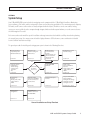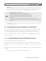
1
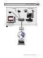
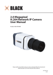
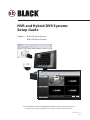
® NVR and Hybrid DVR Systems Setup Guide Products: BLK-SY10 Series Systems BLK-SY20 Series Systems PLEASE READ THIS MANUAL BEFORE USING YOUR SYSTEM, and always follow the instructions for safety and proper use. Save this manual for future reference. BLK-SY10X-20X_SI 3/11/11 CAUTION Operate this system only in environments where the temperature and humidity is within the recommended range. Operation in temperatures or at humidity levels outside the recommended range may cause electric shock and shorten the life of the product. Refer to the specifications for each system component for more information. LEGAL NOTICE SC Black is a registered trademark of Supercircuits, Inc. Supercircuits products are designed to meet safety and performance standards with the use of specific Supercircuits authorized accessories. Supercircuits disclaims liability associated with the use of non-Supercircuits authorized accessories. The recording, transmission, or broadcast of any person’s voice without their consent or a court order is strictly prohibited by law. Supercircuits makes no representations concerning the legality of certain product applications such as the making, transmission, or recording of video and/or audio signals of others without their knowledge and/or consent. We encourage you to check and comply with all applicable local, state, and federal laws and regulations before engaging in any form of surveillance or any transmission of radio frequencies. Other trademarks and trade names may be used in this document to refer to either the entities claiming the marks and names or their products. Supercircuits, Inc. disclaims any proprietary interest in trademarks and trade names other than its own. No part of this document may be reproduced or distributed in any form or by any means without the express written permission of Supercircuits, Inc. © 2010, 2011 Supercircuits, Inc. All rights reserved. 11000 N. Mopac Expressway, Building 300, Austin, TX 78759 Sales/Support: 1.800.335.9777 | Fax: 1.866.267.9777 ii www.sc-black.com Table of Contents SECTION 1 SECTION 2 SECTION 3 SECTION 4 APPENDIX A APPENDIX B APPENDIX C APPENDIX D APPENDIX E Systems Overview. . . . . . . . . . . . . . . . . . . . . . . . . . . . . . . . . . . . . . . . . . . . . . . . . . . . . . . . . . . . . . . . . . . . 2 Getting Started: Unpacking Your System . . . . . . . . . . . . . . . . . . . . . . . . . . . . . . . . . . . . . . . . . . . . . . . . 4 2.1 Unpacking the equipment. . . . . . . . . . . . . . . . . . . . . . . . . . . . . . . . . . . . . . . . . . . . . . . . . . . . . . . . . . . . . 4 System Setup. . . . . . . . . . . . . . . . . . . . . . . . . . . . . . . . . . . . . . . . . . . . . . . . . . . . . . . . . . . . . . . . . . . . . . . . 5 3.1 Check LAN for default IP address compatibility . . . . . . . . . . . . . . . . . . . . . . . . . . . . . . . . . . . . . . . . . . . 6 3.2 Determine the network settings for each IP device. . . . . . . . . . . . . . . . . . . . . . . . . . . . . . . . . . . . . . . . 7 3.3 Install the IPAdmin Tool (for SC-Black IP cameras). . . . . . . . . . . . . . . . . . . . . . . . . . . . . . . . . . . . . . . . . 7 3.4 Install and connect the IP camera/encoder to the LAN. . . . . . . . . . . . . . . . . . . . . . . . . . . . . . . . . . . . . 8 3.5 Repeat for all IP cameras. . . . . . . . . . . . . . . . . . . . . . . . . . . . . . . . . . . . . . . . . . . . . . . . . . . . . . . . . . . . . . 8 3.6 Install the NVR or hDVR hardware. . . . . . . . . . . . . . . . . . . . . . . . . . . . . . . . . . . . . . . . . . . . . . . . . . . . . . 8 3.7 Install analog cameras (hDVR systems only). . . . . . . . . . . . . . . . . . . . . . . . . . . . . . . . . . . . . . . . . . . . . . 8 3.8 Connect analog cameras to the hDVR (hDVR systems only). . . . . . . . . . . . . . . . . . . . . . . . . . . . . . . . . 9 3.9 Install and setup the monitor. . . . . . . . . . . . . . . . . . . . . . . . . . . . . . . . . . . . . . . . . . . . . . . . . . . . . . . . . 11 3.10 Setup the NVR/hDVR system software. . . . . . . . . . . . . . . . . . . . . . . . . . . . . . . . . . . . . . . . . . . . . . . . . . 13 3.10.1 Log in. . . . . . . . . . . . . . . . . . . . . . . . . . . . . . . . . . . . . . . . . . . . . . . . . . . . . . . . . . . . . . . . . . . . . . . . . 14 3.10.2 Configure NVR/hDVR network settings. . . . . . . . . . . . . . . . . . . . . . . . . . . . . . . . . . . . . . . . . . . . . 15 3.10.3 Configuring analog cameras (hDVR systems only) . . . . . . . . . . . . . . . . . . . . . . . . . . . . . . . . . . . 16 3.10.4 Add IP cameras to the system . . . . . . . . . . . . . . . . . . . . . . . . . . . . . . . . . . . . . . . . . . . . . . . . . . . . 18 3.10.5 Naming a camera channel. . . . . . . . . . . . . . . . . . . . . . . . . . . . . . . . . . . . . . . . . . . . . . . . . . . . . . . 22 3.11 Export system configuration. . . . . . . . . . . . . . . . . . . . . . . . . . . . . . . . . . . . . . . . . . . . . . . . . . . . . . . . . . 23 3.12 Setup Reflection software . . . . . . . . . . . . . . . . . . . . . . . . . . . . . . . . . . . . . . . . . . . . . . . . . . . . . . . . . . . 24 3.12.1 Install Reflection . . . . . . . . . . . . . . . . . . . . . . . . . . . . . . . . . . . . . . . . . . . . . . . . . . . . . . . . . . . . . . . 25 3.12.2 Connect Reflection to the NVR/hDVR . . . . . . . . . . . . . . . . . . . . . . . . . . . . . . . . . . . . . . . . . . . . . . 25 Installation Tips . . . . . . . . . . . . . . . . . . . . . . . . . . . . . . . . . . . . . . . . . . . . . . . . . . . . . . . . . . . . . . . . . . . . 28 FAQ. . . . . . . . . . . . . . . . . . . . . . . . . . . . . . . . . . . . . . . . . . . . . . . . . . . . . . . . . . . . . . . . . . . . . . . . . . . . . . . 30 Troubleshooting. . . . . . . . . . . . . . . . . . . . . . . . . . . . . . . . . . . . . . . . . . . . . . . . . . . . . . . . . . . . . . . . . . . . 31 B.1 Camera reset. . . . . . . . . . . . . . . . . . . . . . . . . . . . . . . . . . . . . . . . . . . . . . . . . . . . . . . . . . . . . . . . . . . . . . . 31 B.2 Set to factory default settings. . . . . . . . . . . . . . . . . . . . . . . . . . . . . . . . . . . . . . . . . . . . . . . . . . . . . . . . . 31 B.3 Checking your Firmware . . . . . . . . . . . . . . . . . . . . . . . . . . . . . . . . . . . . . . . . . . . . . . . . . . . . . . . . . . . . . 31 Power over Ethernet. . . . . . . . . . . . . . . . . . . . . . . . . . . . . . . . . . . . . . . . . . . . . . . . . . . . . . . . . . . . . . . . . 32 C.1 PoE compatibility. . . . . . . . . . . . . . . . . . . . . . . . . . . . . . . . . . . . . . . . . . . . . . . . . . . . . . . . . . . . . . . . . . . 32 C.2 Power classification . . . . . . . . . . . . . . . . . . . . . . . . . . . . . . . . . . . . . . . . . . . . . . . . . . . . . . . . . . . . . . . . . 32 Configure the SC Black Camera IP Address . . . . . . . . . . . . . . . . . . . . . . . . . . . . . . . . . . . . . . . . . . . . . . 33 D.1 Connect to the camera with IE . . . . . . . . . . . . . . . . . . . . . . . . . . . . . . . . . . . . . . . . . . . . . . . . . . . . . . . . 34 Device Log. . . . . . . . . . . . . . . . . . . . . . . . . . . . . . . . . . . . . . . . . . . . . . . . . . . . . . . . . . . . . . . . . . . . . . . . . 36 NVR and hDVR Systems Setup Guide 1 SECTION 1: SYSTEM OVERVIEW SECTION 1 Systems Overview SC Black Network Video Recorder (NVR) and Hybrid Digital Video Recorder (hDVR) security systems with the Digital Surveillance Monitoring System software feature state-of-the-art management for advanced analog and IP cameras. The Digital Surveillance Monitoring System software is used to record and store digital video and images, control camera PTZ, and improve the video quality (brightness, contrast, chroma U and V, hue, and gain) of analog cameras. It also includes several surveillance management features including system security and activity logging. All SC Black IP cameras and encoders include an IPAdmin Tool, a Microsoft Windows-based application for configuring IP camera network settings and firmware updates. Depending on your system, the IPAdmin Tool may be pre-installed on your NVR or hDVR. After setting up and configuring your system with the Digital Surveillance Monitoring System software and the IPAdmin tool, use Reflection software (provided) to monitor your system. Reflection is a stand-alone Microsoft® Windows® based video dashboard that connects to the NVR/hDVR across a local network or from the Internet. It provides remote viewing and management of live and recorded video with search, playback and download capabilities. Reflection accesses your cameras and stored video through your NVR or hDVR. It can be used to monitor multiple NVR/hDVR systems concurrently. 2 www.sc-black.com SECTION 1: SYSTEM OVERVIEW IP Cameras Analog Cameras PoE Switch NVR/hDVR IPAdmin Tool Reflection Software = Local System Router Modem Reflection Software NVR and hDVR Systems Setup Guide 3 SECTION 2: GETTING STARTED: UNPACKING YOUR SYSTEM SECTION 2 Getting Started: Unpacking Your System For most installations, SC Black NVR and hDVR systems come with everything needed to install and operate your surveillance system. 2.1 Unpacking the equipment Remove the equipment from its packaging and place it on a flat, clean surface. Inspect each item. If any visible damage is present, contact your supplier or Supercircuits for a replacement. Verify that your order is complete. Within your order you should find: • • • • • The number of cameras you ordered. Each IP camera includes a power supply, a software CD, and a Quick Installation Guide. Depending on your camera model, other items may be included. Monitor with the associated video and power cables, and documentation NVR or hDVR with power cables, keyboard and mouse, remote control, software CD, and documentation. Power over Ethernet (PoE) switch. Accessories you ordered. Refer to the user manual for the product for a list of specific items included with the product. The user manual may be provided on the CD included with the product. NOTE 4 Large systems may be shipped in several cartons. www.sc-black.com SECTION 3: SYSTEM SETUP SECTION 3 System Setup Your SC Black NVR/hDVR system includes the monitoring console computer with the SC Black Digital Surveillance Monitoring System software, a PoE switch, and the analog and IP cameras and encoders that you added to it. The monitoring console computer, PoE switch, and IP cameras and encoders are usually configured with fixed (static) IP addresses on the same subnet. Analog cameras are connected directly to the computer through integrated video and audio capture hardware, or can be connected across the LAN through an IP encoder. Each camera and encoder model has specific installation and usage instructions that should be carefully reviewed when planning the setup of your system. Since many systems include the high-performance SC Black cameras, extra consideration is included herein to aid their installation and setup. The general procedure for installing and setting up your system is shown in the following flow chart. Check network for compatibility with default IP addresses. Determine the network settings for all IP devices. Section 3.1 Section 3.2 Install IP camera in its surveillance location: - Connect audio, etc. - Connect network - Connect power Section 3.4 Configure the camera network settings. Install NVR/hDVR hardware. Install analog in their surveillance locations: - Route power, video audio cables to hDVR Sections 3.7 Section 3.4 Yes Setup the camera configuration: - Video settings - Setup motion detection. - Etc. Section 3.4 Install another IP camera? Section 3.5 No Sections 3.6 Install analog cameras: - Route power, video audio cables to hDVR Connect analog cameras to the hDVR: - Connect video and audio cables Install and setup the monitor. Setup the NVR/hDVR system software: - Configure IP settings - Configure cameras - Configure sensors Sections 3.7 Section 3.8 Section 3..9 Sections 3.10 - 3.10.5 Backup system configuration. Install Reflection software. Connect to the NVR/hDVR. Section 3.11 Section 3.12 General Installation and Setup Flowchart NVR and hDVR Systems Setup Guide 5 SECTION 3: SYSTEM SETUP 3.1 Check LAN for default IP address compatibility All IP devices (computers, cameras, encoders, etc.) are initially setup with factory default network settings. Some devices are preset with fixed (static) IP address, while others acquire their network settings through a DHCP server. Before connecting any IP device with a static IP address to your LAN, check the LAN to ensure that it’s IP address won’t conflict with another device on the LAN. For instance, all SC Black cameras and encoders are factory configured with the static IP address 192.168.0.100. To avoid network conflicts, check the LAN before connecting your camera to ensure that network conflicts won’t occur: 1. 2. At a Microsoft Windows computer attached to the LAN subnet where the camera will be connected (surveillance network), open a Command Prompt window. a. Click the Windows Start button and select Run. b. In the Open field, enter “cmd”, then click OK. At the command prompt, use the ping command to see if the default IP address of your IP device is in use. If the default static IP address is 192.168.0.100, enter: ping 192.168.0.100 The “Request timed out” response indicates that the IP address is not currently in use and the camera can probably be connected without causing conflicts. 6 www.sc-black.com SECTION 3: SYSTEM SETUP A “Reply from ..” message received from a ping indicates that an active device with that IP address exists on the network, and new devices with that address shouldn’t be attached to that network without first changing the network settings of the device. Use the manufacturer’s recommended procedure for changing the address before attaching it to the LAN. For SC Black cameras and encoders To change the IP address before connecting it to the surveillance LAN: NOTE 3. - Determine the new IP address for the device using the procedure outlined in section 3.2 below. - Setup the device temporarily on a LAN where 192.168.0.100 is not in use and power it on. - Install the IPAdmin Tool on a computer on the LAN where the device is temporarily located (see Section 3.3) - Use the IPAdmin Tool to setup the new IP address, subnet mask, and gateway for the device (see Section 3.5 below) - Power off the device and disconnect it from the LAN where it was temporarily setup. It will retain the new network settings you configured it with. Use the ping command to verify that the static IP addresses of other devices in your surveillance system won’t conflict with devices already installed on the LAN. 3.2 Determine the network settings for each IP device Consult with your LAN network administrator to obtain a list of network settings for each IP device, including the NVR or hDVR and all cameras and encoders, you will attach to your LAN. You must use a static IP address for your surveillance system to ensure connectability with the NVR or hDVR. The table included in Appendix E may be useful for logging your network settings. To determine (or verify) which IP addresses are available on your surveillance network, use the ping command as described in section 3.1 to test each address. 3.3 Install the IPAdmin Tool (for SC-Black IP cameras) if you are NOT installing an SC Black IP camera or encoder, skip this section. The IPAdmin Tool, included on the CD disk with all SC Black IP cameras and encoders, will discover all SC Black IP cameras and encoders attached to your network. It is used to perform the initial network setup for each camera and encoder, and install firmware updates. The IPAdmin Tool can be loaded on a Microsoft Windows XP, Vista, or Windows 7 operating system. To install the IPAdmin Tool, do the following: 1. Create a directory on your computer hard drive for the IPAdmin Tool application files. NVR and hDVR Systems Setup Guide 7 SECTION 3: SYSTEM SETUP 2. Insert the CD disk provided with your camera or encoder into your computer’s CD ROM drive and open the CD in a Windows Explorer window. 3. Copy the files IPAdminTool.exe, CgiUtil.dll, and IPAdminTool.dll from the CD to your new directory. 3.4 Install and connect the IP camera/encoder to the LAN 1. Install the IP camera or encoder in the surveillance location in accordance with the manufactures suggested procedure. NOTE If your camera will be powered with a PoE switch, use this switch in the power/LAN connection to verify the functionality of the switch. Refer to Appendix C for more information about PoE powering and your camera. 2. Connect your IP camera to the LAN. Use the manufacturer’s suggested procedure to configure its network settings. For SC Black cameras and encoders, see Appendix D. 3. Adjust the camera video settings, setup the motion detection configuration, etc. if necessary. 4. Verify connectability to the device using network based software as suggested by the manufacturer. For SC Black cameras and encoders, see Appendix D. 3.5 Repeat for all IP cameras Repeat step 3.4 for each camera or encoder you install. Setup one camera at a time to prevent network conflicts between cameras that have the same initial IP address. 3.6 Install the NVR or hDVR hardware Install your NVR or hDVR hardware. Refer to the Quick Start Guide included with the equipment. Do not power on the NVR/hDVR at this time. 3.7 Install analog cameras (hDVR systems only) If you are installing an hDVR system with analog cameras, do the following: 1. Install and setup all analog cameras in their surveillance locations in accordance with the manufactures suggested procedures. 2. Route the video/audio/power extension cable from each camera to the location where the hDVR is installed. 8 www.sc-black.com SECTION 3: SYSTEM SETUP NOTE Typically, the power connectors on video extension cables are different at each end. When routing these cables, ensure that the connectors match the devices they attach to. 3.8 Connect analog cameras to the hDVR (hDVR systems only) Analog cameras are assigned to camera channels in the SC Black Digital Surveillance Monitoring System software by attaching them to the video connector associated with the channel. Similarly, audio sources are associated with camera channels by attaching them to the audio connector associated with the camera channel. 1. Connect the video adapter cables to the video capture card of the computer. The video capture card in some computers accommodate a single 16-channel adapter with BNC and a DVI-style connector, another type provides an 8-channel adapter with BNC and a VGA style connector. Notice that all BNC connectors are labeled for the channel number assigned to the connector. Analog Video Input (DVI-style connector, 8/16 channels) I/O Connections Audio Input Channels (4-channel PC card) Typical Backpanel for an hDVR NVR and hDVR Systems Setup Guide 9 SECTION 3: SYSTEM SETUP 8-channel video adapter cable 2. Connect the audio adapter cable(s) to the audio capture card of the monitoring console computer. The audio capture card may have 4 inputs (numbered 1 – 4, bottom to top), or an audio adapter cable similar to the video adapter cable, but includes RCA female connectors instead of a BNC connectors. 3. Connect the analog camera video cables to the video adapter cable. Note that the each connector is numbered for the assigned camera channel in the SC Black Digital Surveillance Monitoring System software. NOTE 4. If your computer hardware includes a 4-channel audio PC card and you are installing a camera with audio, connect the camera video input to channel 1, 2, 3, or 4. Connectors on the 4-channel audio PC card are for channels 1 – 4, bottom to top. If a camera has an associated audio channel, connect the camera audio input to the audio channel (on the audio adapter cable or 4-channel PC card) marked with the same channel number the camera video cable is connected to. For instance, if the camera video input is attached to the CH 6 connector on the video adapter cable, connect the associated audio input to the CH 6 connector of the audio adapter cable. Make I/O connections If your computer includes an I/O connector terminal block, make connection to sensors (input), relays (output) and an RS485 trunk as needed (see the following diagram). When selecting the wire color and size for these links, follow local codes. 10 www.sc-black.com SECTION 3: SYSTEM SETUP Output 1 Output 2 Ground Input 1 Input 2 Input 3 Input 4 Ground TRX + TRX − RX + RX − I/O Connector Terminal Assignments Sensor inputs can be configured in the SC Black Digital Surveillance Monitoring System software to trigger recording of one camera or several cameras. Sensors and relays can be normally open (NO) or normally closed (NC) type devices. RS485 terminals (TRX +/–, RX +/–) provide a 4-wire RS485 interface. 3.9 Install and setup the monitor If your system includes the Supercircuits LCD17-5, LCD19-5, LDC19W-7, or LCD22W-7 monitor, use the following procedure to setup the monitor. Otherwise, follow the instructions provided by the manufacturer to setup your monitor and connect it to the computer. 1. Find the monitor assembly and base. Use the screw provided to attach the base to the monitor support bracket. The screw may be attached to the underside of the monitor support bracket or in the base. Support Bracket Base Screw 2. Attach the VGA cable provided with the monitor to the VGA input connector on the lower back side of the monitor. Attach the other end of the VGA cable to the VGA connector on the back of the computer. NVR and hDVR Systems Setup Guide 11 SECTION 3: SYSTEM SETUP Inputs on the lower back side of monitor 3. Attach an audio cable with RCA mini jacks to the PC Audio connector on the lower back side of the monitor. 4. Attach the other end of the audio cable to the audio line-out connector on the back of the NVR/hDVR. The audio line out connector is color coded in light green. 5. Attach the power cable to the monitor and plug it into a grounded power outlet. 6. Press the Power button to power on the monitor. The Power button is located in the control panel on the right side of the monitor. SOURCE Move up in menu Move down in menu Move right in menu or volume up Move left in menu or volume down MENU (open/close) Power Audio output Monitor control panel 12 www.sc-black.com SECTION 3: SYSTEM SETUP 7. Press the SOURCE button on the monitor control panel to open the video source menu. Use the p and q buttons on the control panel to highlight PC, and then press the MENU button to select that interface. An indication will appear on the screen confirming your selection. 8. Power off the monitor using the Power button on the control panel. 3.10 Setup the NVR/hDVR system software ! WARNING Make sure the power sources are grounded. This helps prevent personal injury or damage to the equipment. 1. Before connecting the power, ensure that the power source configuration switch on the back of the computer is set to 110 VAC. 2. Make sure all cables are securely attached. 1. Power on the NVR/hDVR. 2. Power on the monitor and wait until the NVR/hDVR is initialized. When fully initialized, the server will display the following SC Black Digital Surveillance Monitoring System multi-image screen. H.264 Network IP Camera User Manual 13 SECTION 3: SYSTEM SETUP Typical SC Black server multi-image display 3.10.1 Log in 1. Click LOG IN (bottom right of screen). 2. Enter a User name and Password in the pop-up Input Password window, and then click OK. The Administrator default User name and Password are admin and admin. When the login is successful, the LOG IN button label changes to TOOLS. Input password 14 www.sc-black.com SECTION 3: SYSTEM SETUP 3.10.2 Configure NVR/hDVR network settings 1. Click TOOLS > Configure > Network to open Network tab. 2. If not already check marked, click the Enable Network option in the upper left corner to select it. 3. In the Enable Network frame, click the Edit button to open the Network Settings window. H.264 Network IP Camera User Manual 15 SECTION 3: SYSTEM SETUP 4. In the Network Connection Settings window, select the network options you prefer, then click OK. NOTE 5. To access the Internet from the system, you must define a DNS server. Contact your system administrator for more information. Attach the Ethernet LAN cable to your NVR/hDVR. 3.10.3 Configuring analog cameras (hDVR systems only) Analog cameras are automatically added to the hDVR system. The video image from the camera will appear on the camera channel associated with the video connector it is physically attached to. If the camera has an associated audio channel, it must be enabled in the SC Black Digital Surveillance Monitoring System software. Use the following procedure to enable audio. Enable analog camera audio channel 1. 16 Click TOOLS > Pause Recording if it appears in the menu, then click OK in the Warning window. Pause Recording only appears in the menu if the hDVR is recording. www.sc-black.com SECTION 3: SYSTEM SETUP 2. Click TOOLS > Configure > Cameras to open the Camera tab. 3. Click the camera icon for the camera channel for which you want to enable audio. In the example shown below, camera channel 1 was selected. Camera Channel Icon Enable Audio Option 4. Click the Enable Audio checkbox to select it. 5. Click the Close button at the bottom of the window. 6. If in Step 1 you selected Pause Recording (the hDVR was in recording), click TOOLS > Start Recording. Otherwise, skip this step. H.264 Network IP Camera User Manual 17 SECTION 3: SYSTEM SETUP 7. Repeat this procedure for each analog camera channel for which you want to enable audio. 3.10.4 Add IP cameras to the system To add IP cameras for NVR/hDVR monitoring, do the following: 1. Click TOOLS > Configure to open the configuration (Preferences) window. By default, the Camera tab is opened. 2. In the Select Camera frame, click on an unused camera channel (red icon). When the channel is selected, the icon is gray. In the example above, camera channel 1 is selected. CAUTION 3. 18 To avoid potential configuration errors in hDVR systems, do not assign IP cameras to channels were analog cameras can reside. Plan your system configuration carefully! In the IP Camera Settings frame, click Add. A Search IP Device window will open. www.sc-black.com SECTION 3: SYSTEM SETUP 4. Click OK to Search in Network and open the IP Device List. 5. In the IP Device List window, select the type of devices attached to the network that you want to add, or select ALL DEVICES, then click Next. The network search will find all devices of the type selected that are supported by the NVR/hDVR. After the search completes, the IP Device window will open and list all devices it found of the type specified. H.264 Network IP Camera User Manual 19 SECTION 3: SYSTEM SETUP 6. In the IP Device window, click a device name you want to add to the NVR/hDVR. In the example above, the first item is selected. Click Next to open the IP Device Details window. 7. In the IP Details window, do the following: a. 20 In the Name field, change the entry to a descriptive name for the camera. In the example above, the Name field contains the default name for SC Black cameras, Black H264. www.sc-black.com SECTION 3: SYSTEM SETUP b. In the User Name and Password fields, enter the user name and password of a user with administrative access to that device. c. In the Channel No. field, select 1 from the pull-down list for stand-alone IP cameras. If the device you are adding is an IP converter (encoder) with multiple channels for analog cameras, select the converter channel number of the analog camera you want to see. For example, if the analog camera is attached to converter channel #3, select 3 from the pull-down list. d. If the device you are adding supports Stream on Motion, PTZ, IP Audio, or Analog Audio, click the appropriate checkbox to select it. e. Click Finish. 8. In the Config (Preferences) Camera tab, click the IP Camera Settings dropdown list and select the Name of the camera you configured in the IP Device Details window. 9. With the Name of the camera showing in the IP Camera Settings field, click the Assign button. H.264 Network IP Camera User Manual 21 SECTION 3: SYSTEM SETUP NOTE Video from the camera will not appear until the Cameras tab is closed and the server is restarted. Add other IP devices to the system as needed before restarting. 10. Repeat steps 2 through 9 above to add other IP cameras (devices) to the NVR/hDVR. 11. In the Camera tab, click Close. 12. When prompted by the server to restart, click Yes. After the server restarts, open the Configure menu and select the channel of the camera(s) you added to see video from the camera(s). NOTE 3.10.5 When the Camera tab is reopened, video from the cameras assigned to the system can be viewed in the Current Recording View window and the Motion Detection Area window by clicking on the camera icon assigned to the camera. In an IP-only system Live video is not shown on the multi-image display. Naming a camera channel The camera channel can be assigned a name that appears on the video image. To rename a camera channel: 1. Click TOOLS > Configure to open the configuration (Preferences) window. By default, the Camera tab is opened. 2. In the Select Camera frame, click on an analog camera channel you want to name. In the example below, camera channel 1 is selected. 3. In the Camera Name frame, click the keyboard icon. Note that the default name for the channel is “Camera 1”. 4. Click the character buttons on the keyboard to enter a new name. To select an uppercase letter, click the Shift button, then click the character button. The entry will appear in the field at the bottom of the keyboard window. 22 www.sc-black.com SECTION 3: SYSTEM SETUP 5. After selecting the new camera name, click the Input button in the keyboard window. The keyboard window will close. 6. To save the entry, click Close in the Camera tab. 3.11 Export system configuration Although catastrophic failures are extremely rare in the DIGIOP system, having the system configuration file backed up enables you to quickly restore the DIGIOP system configuration if that becomes necessary. Also, the configuration file can be used to preconfigure other systems. Whenever changes are made to the system configuration, export the system configuration to an external storage media. To export the system configuration: 1. Click TOOLS > Configure to open the configuration (Preferences) window. By default, the Camera tab is opened. 2. Open the System tab. NVR and hDVR Systems Setup Guide 23 SECTION 3: SYSTEM SETUP Export configuration 3. In the Export/Import frame in lower-right corner of the System tab, click Export. 4. Follow the on-screen instructions to identify the location where the export file will be saved. NOTE 6. The DIGIOP system configuration file is usually smaller than 50 KB. It is named: DIGIOPIPDEVICELIST.DVR Wait until the message “Export successfully completed ...” appears before continuing. 3.12 Setup Reflection software Reflection software should be installed on a Windows PC that can connect to the NVR/hDVR across a network. If the LAN is configured to allow access to the NVR/hDVR through the internet, the Reflection PC can be anywhere that has high-speed internet access. Reflection runs on Microsoft Windows XP Professional with SP2, Windows Vista, and Windows 7. During the installation process, the Reflection installer will also load Microsoft .NET Framework 3.5 SP1. 24 www.sc-black.com SECTION 3: SYSTEM SETUP For more information about Reflection, refer to the Reflection Software User Manual or the Reflection Software Quick Start Guide 3.12.1 Install Reflection Reflection is provided on the Application disk included with your NVR or hDVR hardware. 1. Insert the Application disk into a DVD drive on your computer and find the ReflectionInstaller.exe file. Double click or Run this file to start the installation. 2. Follow the screen prompts to install Reflection on your computer. After you click Finish, the SC icon (see below) will appear on the desktop and in your Windows Start Menu. 3.12.2 Connect Reflection to the NVR/hDVR 1. Start Reflection by double clicking the desktop icon or using the Windows Start menu. 2. Click Login at the bottom of the dialog box to open Reflection. 3. In the Reflection main window, click Configuration > Add > Digiop Video Server in the upper left corner of the window. NVR and hDVR Systems Setup Guide 25 SECTION 3: SYSTEM SETUP 4. Enter the DVR configuration fields with the information necessary to identify your NVR or hDVR. It should include: —— —— —— —— —— —— —— 26 IP Address or Hostname – This is the IP address or the host name of the NVR/hDVR. Username – This is the username that is to be used to access the NVR/hDVR. Password – This is the password associated with the Username. Port – (Visible for data servers only.) The TCP/IP port number that Reflection will use to connect to the NVR/hDVR. The default port number used by Reflection is 24752. Time zone – (Visible for Video Servers only). Select the time zone where the NVR/hDVR is located. Name (optional) – This is the name that identifies the server within Reflection. Description (optional) – This is for a description for the system. www.sc-black.com SECTION 3: SYSTEM SETUP 5. Click Save. Reflection will display the Name of the NVR/hDVR you added in the left panel Systems list. 6. To open a connection to the NVR/hDVR you added, double-click the Name in the left panel. NVR and hDVR Systems Setup Guide 27 SECTION 4: INSTALLATION TIPS SECTION 4 Installation Tips Camera placement Use the information included in the packaging of your camera to mount and connect the unit to power and video cables. Plan your camera installation carefully. Identify the locations where cameras will provide the best coverage, considering: • • • Field of view – Cameras must be positioned so they can effectively view the entire area that must be monitored. Lighting – Is there enough light in the field for the camera to “see” clearly? Is there intense light from the sun or shiny objects that reflect onto the camera lens? These conditions may affect the video quality and camera performance. Ease of installation – Must be able to install the camera at the location, considering mounting hardware requirements, temperature, dust, moisture, etc. Weatherproof cameras Weatherproof cameras can be mounted in any open area, such as on a telephone pole or on the side of a building. However, for best results, we recommend you mount your cameras in a sheltered area, such as under the eave or roof of a building. Point the camera in the direction you wish to observe. When routing cable near the camera, allow enough slack to form a “U” shaped drop to help direct moisture, that accumulates on the cable, away from the camera. NOTE Cable connections are not weatherproof. Cable runs LAN/power cables can be run almost anywhere, and are frequently routed above drop/acoustic ceilings because of the ease of installation. For added security, we recommend you run your cables in areas with limited access to prevent tampering. Avoid running the cable near high voltage appliances such as fluorescent lighting. Electrical noise and magnetic fields produced by these devices may affect video signal quality. A 100’ Ethernet cable is shipped with every camera in your system. Custom-cut cables are also available from Supercircuits. NVR/hDVR placement Your monitoring and recording equipment is central to the accurate capture of video evidence and constant surveillance. Supercircuits strongly suggests that it be installed in a secure location with access limited to authorized personnel. Additionally, NVRs and hDVRs generate heat and should be placed in a well ventilated area. Excessive heat will reduce the life span and reliability of the equipment. 28 www.sc-black.com SECTION 4: INSTALLATION TIPS The monitor does NOT need to be on for recording to take place. NVRs and hDVRs will output and record video regardless of the operational status of the monitor. Uninterruptible power supplies It is strongly suggested that power to the system be routed through an uninterruptible power supply (UPS). These devices will keep your security system running through most power outages, in addition to providing excellent voltage surge and drop protection. The UPS should support your video recorder and all cameras to ensure operation during power outages. NVR and hDVR Systems Setup Guide 29 APPENDIX A: FAQ APPENDIX A FAQ QQ I cannot see video from my camera at the DVR (NVR or hDVR). What can I do to restore the video? AA First, test the connection to the device using the IPAdmin Tool. Can you see all the cameras on your network with this utility? —— —— YES – The LAN and PoE (power) to the camera is probably OK. NO – Check the LAN cable, Ethernet signal, and power at the camera. If faulty, correct the problem and recheck the video streaming. Reset the camera. See Appendix B, Camera reset. Check the camera lens for blockages, dirt, etc. and clean if needed. Use the BNC adapter with the BLK-IPD102 camera or the LOOP connector with the BLK-IPS101 camera to check video. If video is good but still can’t connect, replace the camera. QQ Everything is hooked up and working, but the video that is recorded is jerky and not smooth. Is there something wrong with my system? AA Smoothness of recorded video is dependent upon several factors including compression level, capture size, and the maximum frame rate of your recorder. Most NVR/hDVRs record at frame rates of 30, 90, or 120 frames per second (fps). The frame rate of your NVR/hDVR is divided between each channel being recorded. For example, a 90 fps DVR recording 4 channels will record 22.5 fps per channel, which will appear very smooth. A 120 fps NVR/hDVR recording 9 channels will record 13 fps, which will appear less smooth and fluid, particularly when compared to a TV broadcast at 29.97 fps. If there are irregular gaps in the video, or a momentary loss of video, there could be problems in the system. Call Supercircuits at 1-800-335-9777 for assistance. QQ Why can’t I get a good picture from one of my cameras? The camera’s power light is blinking or flickering. AA This is usually a symptom of low voltage at the camera. You may have a cable run that is too long, a defective cable, or an insufficient power supply. Try using a better quality cable, or plug the power adapter directly into the camera to bypass the cable all together. QQ I installed the cables to my analog video equipment, but the power plug won’t fit into the camera or the power adapter: AA Chances are you’ve run the cable backwards. Only one end of the camera cables supplied by Supercircuits will fit the camera, while only the other end will fit the power adapter. The cable will need to be pulled, and run the other direction. 30 www.sc-black.com APPENDIX B: TROUBLESHOOTING APPENDIX B Troubleshooting B.1 Camera reset To reset the camera while it is in use: NOTE The BLK-IPD101 camera does not have a hardware Reset button. 1. Press and hold the Reset button for 3 seconds. 2. Wait for the camera to reboot. B.2 Set to factory default settings The camera network settings can be forced to the initial (factory default) settings: • • • • • IP address – reset to 192.168.0.100 Subnet mask – reset to 255.255.255.0 Gateway – reset to 192.168.0.1 User ID – reset to root Password – reset to pass To force the camera to the factory settings: 1. Disconnect the power (adapter) from the device. 2. While pressing and holding down the Reset button, connect the power to the camera. 3. Release the Reset button 5 seconds after powering on the camera. 4. Wait for the camera to reboot. B.3 Checking your Firmware Firmware is software embedded in the camera that determines many of its features and functionality. The current firmware version of your camera can be found by viewing video from the camera in IE, and then clicking SETUP > About > Version. To replace or update the firmware in your camera, contact the Supercircuits Support Team. NVR and hDVR Systems Setup Guide 31 APPENDIX C: POWER OVER ETHERNET APPENDIX C Power over Ethernet Some SC Black cameras and encoders support Power over Ethernet (PoE) in conformance with the IEEE 802.3af standard. IEEE 802.3af allows for two power options for Category 5 (Cat5) cables. The PoE module signature and control circuit provides the PoE compatibility signature and power classification required by the Power Sourcing Equipment (PSE) before applying up to 15 W power to the port. The high efficiency AC/DC converter operates over a wide input voltage range and provides a regulated low ripple and low noise output. The AC/DC converter also has built-in overload and short-circuit output protection. • • C.1 PoE compatibility With non Power Sourcing Equipment (PSE) When it is connected with non PSE, use the power adaptor to provide power to the camera. With power adaptor Connecting both a PSE and a power adaptor does not do any harm to the products. Disconnecting the power adaptor while it is operating does not stop operation. The product continues to work without rebooting. C.2 Power classification The PoE Power Class supported by the IP device is Class 0. Class Usage Minimum Power Levels Output at the PSE Maximum Power Levels at the Powered Device 0 Default 15.4 W 0.44 to 12.95 W 32 www.sc-black.com APPENDIX D: CONFIGURE THE SC BLACK CAMERA IP ADDRESS APPENDIX D Configure the SC Black Camera IP Address 1. Open the Windows directory where you installed IPAdmin Tool. Double click IPAdminTool.exe to start the application. When the IPAdmin Tool starts, it will discover all of the support IP cameras and encoders that exist on the network. The discovery process may take several minutes. IPAdmin Tool discovered 192.168.0.100 NOTE When a camera is powered on, it will not respond to network commands until it is fully initialized. The initialization process can take up to 2 minutes. 2. In the Product list, find the entry with the same MAC address as the camera you are configuring. If the camera is not shown, click Refresh repeatedly to update the list. 3. Right click on the entry for your camera and select IP Address. 4. In the IP Setup window: a. Select the Static option if it is not selected. This option is required to record camera video by a network NVR or hDVR. NVR and hDVR Systems Setup Guide 33 APPENDIX D: CONFIGURE THE SC BLACK CAMERA IP ADDRESS IP Setup window 5. b. Enter the new IP address, subnet mask, and gateway address into the appropriate fields. c. Click SETUP. A Login window will open. d. In the Login window, enter the ID and PW (password) for your camera and click Login. The default administrator values for the ID and PW are root and pass. After entering the ID and PW, the IP Setup window will close. In the IPAdmin Tool window, click Refresh and verify that the entry representing the camera now shows the new IP address. D.1 Connect to the camera with IE To further test the connectability of the camera (network settings) and verify video streaming: 1. Open Microsoft Internet Explorer (IE). 2. In the Internet address field, enter the newly configured IP address for your camera in the format: http://<IP address>/ Where <IP address> is the IP address of your camera. For example, if the new IP address of the camera is 192.168.1.201, enter: http://192.168.1.201 34 www.sc-black.com APPENDIX D: CONFIGURE THE SC BLACK CAMERA IP ADDRESS 3. If prompted to install an ActiveX control such as AxNVC.cab, follow screen prompts to install the software. IE prompt to install ActiveX control NOTE If you cannot see live video after logging into your camera and the following message appears: “Can not Create XMLDOMDocument Install MSXML4.0”, download and install the MS XML 4.0 library. The library can be found at: http://www.microsoft.com/downloads/details.aspx?familyid=3144B72B-B4F2-46DA-B4B6-C5D7485F2B42&displaylang=en After loading ActiveX controls and updating your XML library, a video stream from the camera should appear. NVR and hDVR Systems Setup Guide 35 APPENDIX E: DEVICE LOG APPENDIX E Device Log The following table is provided as an aid to setting up and logging the IP devices on your network. 36 NVR/hDVR Description/SKU MAC address IP Address Subnet Mask Gateway Location IP Device Summary www.sc-black.com APPENDIX E: DEVICE LOG Analog Camera Device Summary hDVR Channel Camera Model Audio (Y/N) Location 1 2 3 4 5 6 7 8 9 10 11 12 13 14 15 16 NVR and hDVR Systems Setup Guide 37