1
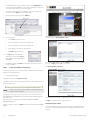
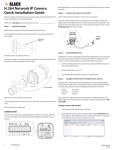
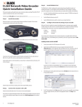
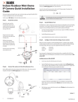
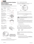
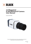
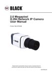
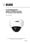
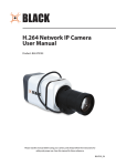
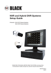
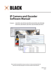
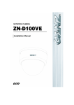
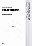
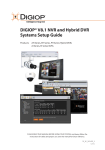
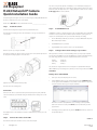
2.0 Megapixel H.264 Network IP Camera Quick Installation Guide Your camera can be powered locally with a 12 V DC adapter, or across the LAN (PoE). If using the power adapter, attach the DC jack adapter cable to the DC 12V power adapter terminals on the back of the camera. Connect the red wire of the adapter cable to the + terminal, and the black (or white) wire to the - terminal. DO NOT apply power to the camera at this time. DC Jack Adapter Cable This document guides you through the basic steps to install and configure your Digiop® Black BLK-IPS102M IP camera. For detailed instructions, refer to the User Manual. Find the camera’s MAC address on the product label and enter it here: __________________ Step 1. Install the camera Install the camera mounting bracket using the instructions provided with the bracket. Step 3. Attach the adapter for mounting the camera to side with the label or to the opposite side with the four screws provided. The IPAdminTool is a utility for configuring the network settings of your Digiop Black cameras and installing new firmware. It can be loaded on a Microsoft Windows XP, Vista or Windows 7 operating system. At a computer on the same LAN (subnet) where your cameras will be installed, do the following: Mounting adapter Install IPAdmin Tool 1. Insert the CD mini disk provided with your camera into your computer’s CD ROM drive and open the CD in a Windows Explorer window. 2. Find the IPAdminTool directory on the CD. 3. Copy the IPAdminTool directory with its contents to your computer hard drive. Remove the protective cap covering the camera CCD. Step 4. Configure the network settings of you camera Attach the lens assembly to the camera by screwing it clockwise onto the camera until it is fully seated. The lens may require a mounting ring adapter to fit onto the camera. When your IP camera is attached to a network and initially powered on, it attempts acquire compatible network settings from a DHCP server. If it cannot find a DHCP server, it configures itself with the following static (fixed) settings, which may or may not be compatible with other devices on the network. IP address: Subnet mask: Gateway: 192.168.0.100 255.255.255.0 192.168.0.1 Your camera must be configured with static network settings that are compatible with the LAN. If your LAN has a DHCP server, use the following sub-step. Otherwise, use the sub-step procedure below for LANs without DHCP. Installing cameras on LANs with DHCP 1. Connect your camera to the LAN, then power on the camera. 2. Open the IPAdminTool directory on your computer, then double click the file IPAdminTool.exe to start the application. When the IPAdmin Tool starts, it will discover all the IP devices it supports that exist on the network. The discovery process may take a few minutes. Tighten the lens set screw with the hex wrench provided. Attach the camera to the mounting bracket. Connections Connections to the camera for audio in and out (microphone and speaker), DI sensor, alarm, and RS‑485 control are made through a 9-pin terminal block. Plug the terminal block into the mating connector on the camera. Review the list of IP devices found by IPAdmin Tool. You can identify your camera by the MAC address. If the camera was not found, click the Refresh button every minute until your camera appears in the list. 3. Attach peripheral devices to the terminal block as needed. For detailed interface specifications, refer to the User Manual. Step 2. Connect the camera to the LAN After finding your camera, right click the entry, then select IP Address from the drop-down list. An IP Setup window will open. Continue Attach the network LAN cable to the Ethernet connector on the camera backpanel. 1 www.digiop.com BLK-IPS102M_CQ 5/27/11 Static Option Check LAN for default IP address compatibility Before connecting your camera to the LAN, check the network to see if IP address 192.168.0.100 is already in use. At a Microsoft Windows computer attached to the LAN where the camera will be connected, open a Command Prompt window and enter: ping 192.168.0.100 4. In the IP Setup window, click the Static option bullet. If you have other compatible network settings you want to apply to the device, enter them in the appropriate locations. Click Setup to save settings. 5. In the Login window, enter the ID and PW (password) for your camera, then click Login. The default administrator values for the ID and PW are root and pass. The “Request timed out” response indicates that the IP address is not in use and the camera can be connected without causing conflicts. If the response from the ping command received a “Reply..”, the IP address is in use. Contact Technical Support for further assistance, if needed. Find network settings (IP addresses) that are not in use 6. In the IPAdmin Tool window, click Refresh. Verify that the entry representing the camera now shows the (new) static IP address. 7. Continue with procedure Step 5. Setup camera Basic Configuration. 1. At your PC, find an IP address on your network that is not in use: a. Write down the EXACT IP address of your PC up to the third/last period. Using the example shown above, this expression is: 192.168.1. After the third period, include any number between 1 and 254 that is different from the one in your PC’s IP address, 168. As a first try, let’s choose 200, which will form the IP address 192.168.1.200. b. Next, use the ping command in the Command Prompt window to see if this IP address is in use on your network. Enter: ping 192.168.1.200. Installing cameras on LANs without DHCP In networks without a DHCP server, cameras must be powered on and reconfigured one at a time to avoid addressing conflicts between other cameras, or possibly with another device on the network. Configuring the network settings of your cameras includes these steps: —— —— —— —— Determine the network settings of your computer. Check the network for compatibility with the default static network settings of your camera. Find an IP address that is not in use and can be assigned to your camera. Attach your camera to the network, power it on, and configuring it with new network settings. Determine the network settings of your computer 1. At a PC attached to the LAN where your camera will be connected, determine the IP address, subnet mask, and default gateway of your PC. To find this information: a. Hold down the Windows key and press r to open the Run dialog box. b. Type cmd in the entry field, then click OK to open the Command Prompt window. c. d. NOTE 2 In the example shown above, the message “Reply from 192.168.1.200: ..” indicates that your PC can reach a device with that IP address, and that address is in use (i.e., you cannot use it for your camera). c. Since the ping test showed that 192.168.1.200 is in use, try another number between 1 and 254. Let’s try to ping 192.168.1.201. At the command prompt, enter: ping 192.168.1.201 d. In this test, the message “Request timed out” indicates that your PC cannot reach the device with that IP address, and that address is probably not in use. If this test showed that this IP address is in use, try other IP addresses using the steps above until an unused address is found. At the command prompt, enter ipconfig. The response will show the your PC’s network settings. Record the IP Address, Subnet Mask, and Default Gateway for your PC’s Ethernet adapter for future reference. The Ethernet adapter data you see by using ipconfig will probably be different from that shown in the example above. If you are using Windows Vista or Windows 7, the IP address is identified as the “IPv4 Address.” www.digiop.com Attach your camera to the network, power it on, and configuring it with new network settings 1. Connect the camera to the LAN and apply power to the camera. Wait until the initialization process completes (2 to 4 minutes) before continuing. © 2011 DIGIOP, Inc. All rights reserved. 2. Open the IPAdminTool directory on your computer, then double click the file IPAdminTool.exe to start the application. When the IPAdmin Tool starts, it will discover all the IP devices it supports that exist on the network. The discovery process may take a few minutes. 3. In the Product list, find the entry with the same MAC address as the camera you installed. If the camera is not shown, click Refresh once a minute to update the list. 4. Right click on the entry for your camera and select IP Address. Static Option 5. In the IP Setup window: a. Select the Static option if it is not selected. b. Enter the new IP address for your camera into the IP Address field. c. Enter the subnet mask of your computer into the Subnet Mask field. d. Enter the gateway of your computer into the Gateway field. e. Click SETUP. A Login window will open. 6. In the Login window, enter the ID and PW (password) for your camera and click Login. The default administrator values for the ID and PW are root and pass. 7. In the IPAdmin Tool window, click Refresh. Verify that the entry representing the camera now shows the new IP address. Step 5. Setup camera Basic Configuration In the SETUP window, go to Basic Configuration > Users. In the User list, click root to highlight it, and then click Modify. Enter a new password and click OK. In the Users screen, click Apply, and then click OK to restart the server. Go to Basic Configuration > Date & Time. To view video images from the camera, at a computer attached to the LAN where the camera is installed, open Microsoft© Internet Explorer and go to: http://<IP address of the camera> If the IP address is 192.168.1.201, enter: http://192.168.1.201 If prompted to install ActiveX controls such as AxAll.cab (publisher Cap Co), AxPTZ, or AxNVC, follow screen prompts to install the software. NOTE To load these ActiveX controls, you may need to adjust the security settings of your browser to accept add-ins from unknown publishers. After logging into your camera, if you cannot see live video from the camera and the message: “Can not Create XMLDOMDocument Install MSXML4.0” appears, download and install the MS XML 4.0 library. This library can be found at: http://www.microsoft.com/downloads/details.aspx?familyid=3144B72B-B4F2-46DA-B4B6C5D7485F2B42&displaylang=en After the camera VIEW screen appears, click SETUP and enter the default User name and Password, root and pass. 3 www.digiop.com On the Date & Time screen, set the Time Zone, Method, and Time Synchronization options. Click Apply. Click VIEW to exit SETUP mode and return to the live viewing screen. Aim and Focus the camera Set focus and zoom while observing video image from the camera. Video is provided through the web browser. Use the documentation provided with your camera mounting bracket and lens to make these adjustments. © 2011 Digiop, Inc. All rights reserved.