1
Sun Fire X4170 M2 Server
Service Manual
Part No. E22369-02
May 2011, Revision A
Copyright © 2010, Oracle and/or its affiliates. All rights reserved.
This software and related documentation are provided under a license agreement containing restrictions on use and disclosure and are protected by
intellectual property laws. Except as expressly permitted in your license agreement or allowed by law, you may not use, copy, reproduce, translate,
broadcast, modify, license, transmit, distribute, exhibit, perform, publish, or display any part, in any form, or by any means. Reverse engineering,
disassembly, or decompilation of this software, unless required by law for interoperability, is prohibited.
The information contained herein is subject to change without notice and is not warranted to be error-free. If you find any errors, please report them to us
in writing.
If this is software or related software documentation that is delivered to the U.S. Government or anyone licensing it on behalf of the U.S. Government, the
following notice is applicable:
U.S. GOVERNMENT RIGHTS. Programs, software, databases, and related documentation and technical data delivered to U.S. Government customers
are "commercial computer software" or "commercial technical data" pursuant to the applicable Federal Acquisition Regulation and agency-specific
supplemental regulations. As such, the use, duplication, disclosure, modification, and adaptation shall be subject to the restrictions and license terms set
forth in the applicable Government contract, and, to the extent applicable by the terms of the Government contract, the additional rights set forth in FAR
52.227-19, Commercial Computer Software License (December 2007). Oracle America, Inc., 500 Oracle Parkway, Redwood City, CA 94065.
This software or hardware is developed for general use in a variety of information management applications. It is not developed or intended for use in any
inherently dangerous applications, including applications which may create a risk of personal injury. If you use this software or hardware in dangerous
applications, then you shall be responsible to take all appropriate fail-safe, backup, redundancy, and other measures to ensure its safe use. Oracle
Corporation and its affiliates disclaim any liability for any damages caused by use of this software or hardware in dangerous applications.
Oracle and Java are registered trademarks of Oracle and/or its affiliates. Other names may be trademarks of their respective owners.
AMD, Opteron, the AMD logo, and the AMD Opteron logo are trademarks or registered trademarks of Advanced Micro Devices. Intel and Intel Xeon are
trademarks or registered trademarks of Intel Corporation. All SPARC trademarks are used under license and are trademarks or registered trademarks of
SPARC International, Inc. UNIX is a registered trademark licensed through X/Open Company, Ltd.
This software or hardware and documentation may provide access to or information on content, products, and services from third parties. Oracle
Corporation and its affiliates are not responsible for and expressly disclaim all warranties of any kind with respect to third-party content, products, and
services. Oracle Corporation and its affiliates will not be responsible for any loss, costs, or damages incurred due to your access to or use of third-party
content, products, or services.
Copyright © 2010, Oracle et/ou ses affiliés. Tous droits réservés.
Ce logiciel et la documentation qui l’accompagne sont protégés par les lois sur la propriété intellectuelle. Ils sont concédés sous licence et soumis à des
restrictions d’utilisation et de divulgation. Sauf disposition de votre contrat de licence ou de la loi, vous ne pouvez pas copier, reproduire, traduire,
diffuser, modifier, breveter, transmettre, distribuer, exposer, exécuter, publier ou afficher le logiciel, même partiellement, sous quelque forme et par
quelque procédé que ce soit. Par ailleurs, il est interdit de procéder à toute ingénierie inverse du logiciel, de le désassembler ou de le décompiler, excepté à
des fins d’interopérabilité avec des logiciels tiers ou tel que prescrit par la loi.
Les informations fournies dans ce document sont susceptibles de modification sans préavis. Par ailleurs, Oracle Corporation ne garantit pas qu’elles
soient exemptes d’erreurs et vous invite, le cas échéant, à lui en faire part par écrit.
Si ce logiciel, ou la documentation qui l’accompagne, est concédé sous licence au Gouvernement des Etats-Unis, ou à toute entité qui délivre la licence de
ce logiciel ou l’utilise pour le compte du Gouvernement des Etats-Unis, la notice suivante s’applique :
U.S. GOVERNMENT RIGHTS. Programs, software, databases, and related documentation and technical data delivered to U.S. Government customers
are "commercial computer software" or "commercial technical data" pursuant to the applicable Federal Acquisition Regulation and agency-specific
supplemental regulations. As such, the use, duplication, disclosure, modification, and adaptation shall be subject to the restrictions and license terms set
forth in the applicable Government contract, and, to the extent applicable by the terms of the Government contract, the additional rights set forth in FAR
52.227-19, Commercial Computer Software License (December 2007). Oracle America, Inc., 500 Oracle Parkway, Redwood City, CA 94065.
Ce logiciel ou matériel a été développé pour un usage général dans le cadre d’applications de gestion des informations. Ce logiciel ou matériel n’est pas
conçu ni n’est destiné à être utilisé dans des applications à risque, notamment dans des applications pouvant causer des dommages corporels. Si vous
utilisez ce logiciel ou matériel dans le cadre d’applications dangereuses, il est de votre responsabilité de prendre toutes les mesures de secours, de
sauvegarde, de redondance et autres mesures nécessaires à son utilisation dans des conditions optimales de sécurité. Oracle Corporation et ses affiliés
déclinent toute responsabilité quant aux dommages causés par l’utilisation de ce logiciel ou matériel pour ce type d’applications.
Oracle et Java sont des marques déposées d’Oracle Corporation et/ou de ses affiliés.Tout autre nom mentionné peut correspondre à des marques
appartenant à d’autres propriétaires qu’Oracle.
AMD, Opteron, le logo AMD et le logo AMD Opteron sont des marques ou des marques déposées d’Advanced Micro Devices. Intel et Intel Xeon sont des
marques ou des marques déposées d’Intel Corporation. Toutes les marques SPARC sont utilisées sous licence et sont des marques ou des marques
déposées de SPARC International, Inc. UNIX est une marque déposée concédée sous licence par X/Open Company, Ltd.
Ce logiciel ou matériel et la documentation qui l’accompagne peuvent fournir des informations ou des liens donnant accès à des contenus, des produits et
des services émanant de tiers. Oracle Corporation et ses affiliés déclinent toute responsabilité ou garantie expresse quant aux contenus, produits ou
services émanant de tiers. En aucun cas, Oracle Corporation et ses affiliés ne sauraient être tenus pour responsables des pertes subies, des coûts
occasionnés ou des dommages causés par l’accès à des contenus, produits ou services tiers, ou à leur utilisation.
Please
Recycle
Contents
Preface
1.
xi
Sun Fire X4170 M2 Server Overview
1.1
Product Description
1.2
Server Chassis Overview
1–1
1–1
1–4
1.2.1
Infrastructure Boards
1–4
1.2.2
Dimensions and Weight
1.2.3
Internal System Cables
1–5
1–6
1.3
Server Front Panel Features
1–6
1.4
Server Back Panel Features
1–7
1.5
Server Status Indicators and LEDs
1–8
1.5.1
Server General Status Indicators
1.5.2
Server Fan LEDs
1.5.3
Storage and Boot Drive LEDs
1.5.4
Power Supply LEDs
1.5.5
Motherboard LEDs
1–9
1–10
1–11
1–11
1–12
1.5.5.1
DDR3 DIMM Fault LEDs
1–12
1.5.5.2
CPU Fault LEDs
1.5.5.3
Fault Remind Super Capacitor Power LED
1.5.5.4
3.3V_STANDBY OK LED
1–12
1–12
1–13
iii
2.
Preparing to Service the System
2.1
Safety Information
2.2
Required Tools
2.3
Obtaining the Chassis Serial Number
2.4
Powering On and Off the Server
2.5
2–1
2–2
2–2
2–3
2.4.1
Power On the Server
2–3
2.4.2
Power Off the Server
2–4
2.4.3
Power Off the Server Using the ILOM SP Command-Line
Interface 2–4
About the BIOS
2.5.1
2–5
BIOS Booting and Setup Considerations
Default BIOS Power-On Self-Test (POST) Events
2.5.1.2
BIOS POST F1 and F2 Errors
2.5.1.3
How BIOS POST Memory Testing Works
2–10
2.5.1.4
Ethernet Port Device and Driver Naming
2–11
2.5.1.5
Ethernet Port Booting Priority
2.5.1.6
Hardware Prefetchers
BIOS Setup Utility Menus
2.5.3
BIOS Setup Utility Hot Keys
2.5.4
Accessing the BIOS Setup Utility Menus
2.5.6
2.5.7
2–7
2–12
2–12
2–14
2–14
Access BIOS Setup Utility Menus
Configuring Support for TPM
2.5.5.1
2–6
2–12
2.5.2
2.5.5
2–6
2.5.1.1
2.5.4.1
2–14
2–17
Configure TPM Support in BIOS
Configuring SP LAN Settings
2–17
2–22
2.5.6.1
Configure LAN Settings for SP
2.5.6.2
Viewing or Setting the ILOM SP IP Address Using the
BIOS Setup Utility 2–24
Configuring Option ROM Settings in BIOS
2.5.7.1
iv
2–1
2–23
2–24
Enable or Disable Option ROM Settings
Sun Fire X4170 M2 Server Service Manual • May 2011
2–25
2.5.8
2.6
2.9
2–29
Filler Panel Purpose
2.8.2
Filler Panel Removal and Installation
2–29
Electrostatic Discharge Safety Measures
Using an Antistatic Wrist Strap
2.9.1.2
Using an Antistatic Mat
Using ESD Handling Precautions
Removing the Top Cover
3.3
2–32
2–32
2–32
2–33
Remove Top Cover
2–33
3–1
Hot-Pluggable Versus Hot-Swappable Devices
3.1.1
Hot-Pluggable Devices
3.1.2
Hot-Swappable Devices
Servicing Storage Drives
3–1
3–1
3–2
3–2
3.2.1
Server Storage Drive Locations
3.2.2
Storage Drive Status LED Reference
3.2.3
Remove Storage Drive
3.2.4
Install Storage Drive
Servicing Fan Modules
2–
2–31
2.9.1.1
Servicing Customer-Replaceable Devices
3.2
2–30
Performing Electrostatic Discharge and Antistatic Prevention Measures
31
2.10.1
3.1
2–28
2.8.1
2.9.2
3.
2–26
2–27
Remove Server From the Rack
Using Server Filler Panels
2.9.1
2.10
2–26
Extend Server to the Maintenance Position
Removing the Server From the Rack
2.7.1
2.8
2–26
Extending the Server to the Maintenance Position
2.6.1
2.7
Updating the BIOS Firmware
3–2
3–3
3–4
3–5
3–7
3.3.1
About Server Fans
3–7
3.3.2
Detecting Fan Module Failure
3–8
Contents
v
3.4
4.
Fan Module Status LEDs
3.3.4
Remove Fan Module
3.3.5
Install Fan Module
Servicing Power Supplies
3–8
3–9
3–10
3–12
3.4.1
Detecting Power Supply Failure
3.4.2
Power Supply LED Reference
3.4.3
Remove Power Supply
3.4.4
Install Power Supply
3–12
3–15
4–1
4.1
Motherboard Component Locations
4.2
Servicing DDR3 DIMMs
4.4
3–12
3–13
Servicing Motherboard Components
4.3
vi
3.3.3
4–2
4–3
4.2.1
DIMM and CPU Physical Layout
4.2.2
DIMM Population Rules
4.2.3
DIMM Rank Classification Labels
4.2.4
Locations of Faulty DIMMs Using ILOM Versus BIOS
4.2.5
Inconsistencies Between DIMM Fault LEDs and the BIOS Mapping
of Faulty DIMMs 4–8
4.2.6
Remove Faulty DDR3 DIMMs
4.2.7
Install DDR3 DIMMs
4.2.8
Error Correction and Parity
Servicing PCIe Risers
4–5
4–7
4–8
4–11
4–13
4–13
4.3.1
Remove PCIe Riser
4.3.2
Install PCIe Riser
Servicing PCIe Cards
4–4
4–14
4–16
4–17
4.4.1
Supported PCIe Cards
4.4.2
PCIe Card Configuration Guidelines
4.4.3
Remove PCIe Card
4.4.4
Install PCIe Card
Sun Fire X4170 M2 Server Service Manual • May 2011
4–18
4–19
4–21
4–19
4–7
4.5
4.6
4.7
4.8
5.
Servicing the Battery
4–23
4.5.1
Remove Battery
4.5.2
Install Battery
Servicing CPUs
4–23
4–24
4–25
4.6.1
Remove CPU
4.6.2
Install CPU
4–25
4–29
4.6.2.1
Replace Faulty CPU
4.6.2.2
Upgrade Server to Two CPUs
Servicing the Motherboard
4.7.1
Remove Motherboard
4.7.2
Install Motherboard
4–34
4–36
Resetting Passwords and Clearing CMOS NVRAM
Overview
4–39
4.8.2
Reset the BIOS Password and Clear the CMOS NVRAM Using the
CLR CMOS Button 4–39
5–1
Infrastructure Component Locations
5.2
Servicing the DVD/USB Module
5.5
4–39
4.8.1
5.1
5.4
4–32
4–33
Servicing Infrastructure Components
5.3
4–30
5–3
5.2.1
Remove DVD/USB Module
5.2.2
Install DVD/USB Module
Servicing the Fan Board
5–3
5–4
5–5
5.3.1
Remove Fan Board
5.3.2
Install Fan Board
5–5
5–7
Servicing the Storage Drive Cage
5–9
5.4.1
Remove Storage Drive Cage
5.4.2
Install Storage Drive Cage
Servicing the Disk backplane
5.5.1
5–2
5–9
5–11
5–12
Remove Disk Backplane
5–13
Contents
vii
5.5.2
5.6
5.7
5.8
5.9
6.
5–14
Servicing the Front Control Panel Light Pipe Assembly
Remove Front Control Panel Light Pipe Assembly
5.6.2
Install Front Control Panel Light Pipe Assembly
Servicing the Power Distribution Board
Remove Power Distribution Board
5.7.2
Install Power Distribution Board
Servicing the Paddle Board
Remove Paddle Board
5.8.2
Install Paddle Board
5–18
5–20
5–22
5–24
5–25
5.9.1
Remove Storage Drive Cables From a SAS Configuration
5.9.2
Install Storage Drive Cables in a SAS Configuration
5.9.3
Remove Storage Drive Cables in a SATA Configuration
5.9.4
Install Storage Drive Cables in a SATA Configuration
5.9.5
Change Storage Drive Cables From SAS to SATA Configuration
33
5.9.6
Change Storage Drive Cables From SATA to SAS
5.9.7
Remove Fan Board Cables
5.9.8
Install Fan Board Cables
5.9.9
Remove Power Distribution Board Cable
5.9.10
Install Power Distribution Board Cable
Installing the Top Cover
5–33
5–34
5–35
5–35
6–1
6–1
Install Top Cover
6–1
Reinstalling the Server in the Rack
6.2.1
6.3
5–17
5–22
5.8.1
Servicing Cables
5–16
5–18
5.7.1
6.1.1
6.2
5–16
5.6.1
Returning the Server to Operation
6.1
viii
Install Disk Backplane
Reinstall Server in Rack
6–3
6–3
Returning the Server to the Normal Rack Position
Sun Fire X4170 M2 Server Service Manual • May 2011
6–4
5–26
5–28
5–29
5–31
5–33
5–
6.3.1
6.4
7.
Return the Server to the Normal Rack Position
Powering On the Server
6–4
6–6
Troubleshooting the Server and Restoring ILOM Defaults
7.1
7.2
Troubleshooting the Server
7–2
7.1.1
Oracle Diagnostic Tools
7.1.2
Diagnostic Tool Documentation
Using the Preboot Menu Utility
7.2.1
7.2.2
7.2.5
7–4
7–5
7–5
7.2.1.1
Prerequisites for Accessing the Preboot Menu
7.2.1.2
Access the Preboot Menu
7.2.1.3
Edit Preboot Menu for Remote Serial Access
7.2.1.4
Edit Mode Settings in Preboot Menu
Restoring ILOM to Default Settings
7–6
7–7
7–8
7–10
7–10
Resetting ILOM Configuration Using the Preboot
Menu 7–10
Restoring ILOM Access to the Serial Console
7.2.3.1
7.2.4
7–2
Accessing the Preboot Menu
7.2.2.1
7.2.3
7–1
7–11
Restore Access to the Serial Console Using the Preboot
Menu 7–11
Restoring the SP Firmware Image
7–12
7.2.4.1
Prerequisite for Restoring SP Firmware Using Preboot
Menu 7–12
7.2.4.2
Restore the SP Firmware Image Using the Preboot
Menu 7–13
Preboot Menu Command Summary
A. Connector Pinouts
7–14
A–1
A.1
Serial Management Port Connector
A–2
A.2
Network Management Port Connector
A.3
Video Connector
A–4
A.4
USB Connectors
A–5
A–3
Contents
ix
A.5
Gigabit Ethernet Connectors
A–6
B. Sun Fire X4170 M2 Server Illustrated Parts Breakdown
B.1
Server Components
C. Configuring BIOS Settings
C–1
C.1
BIOS Setup Screens Overview
C.2
BIOS Setup Utility Menu Screens
C–3
C.2.1
BIOS Main Menu Screens
C–4
C.2.2
BIOS Advanced Menu Screens
C.2.3
BIOS PCI Menu Screen
C.2.4
BIOS Boot Menu Screens
C.2.5
BIOS Security Menu Screen
C–8
C.2.6
BIOS Chipset Menu Screens
C–9
C.2.7
BIOS Exit Menu Screen
▼
Index
x
B–2
C–2
C–6
C–7
C–10
Executing a BIOS Exit Option
Index–1
Sun Fire X4170 M2 Server Service Manual • May 2011
C–5
C-10
B–1
Preface
This service manual provides detailed procedures for removing and replacing
components in the Sun Fire X4170 M2 Server from Oracle®. This document also
includes information about the use and maintenance of the server.
It is written for technicians, system administrators, authorized service providers, and
users who have advanced experience troubleshooting and replacing hardware.
This preface contains the following topics:
■
“Product Information” on page xi
■
“Related Documentation” on page xii
■
“Documentation, Support, and Training” on page xiv
■
“Typographic Conventions” on page xiv
■
“Documentation Comments” on page xiv
Product Information
For information about the Sun Fire X4170 M2 Server, go to the following web site:
http://www.oracle.com/goto/x4170m2
At that site, you can find links and navigate to the following information and
downloads:
■
Product information and specifications
■
Supported operating systems
■
Software and firmware downloads
■
Supported option cards
■
External storage options
xi
■
Power calculator
■
Systems Handbook
Related Documentation
The related documents listed in the following table are available online at:
http://docs.sun.com/app/docs/prod/sf.x4170m2#hic
xii
Title
Content
Part Number
Format
Sun Fire X4170 M2 and X4270
M2 Servers Product Notes
Late-breaking information
about the server
821-0482
PDF
HTML
Sun Fire X4170 M2 and X4270
M2 Servers Getting Started
Guide
Basic installation information
for setting up the server
821-0480
PDF
Print
Sun Fire X4170 M2 and X4270
M2 Servers Installation Guide
Detailed installation
information for setting up the
server
821-0481
PDF
HTML
Print option
Sun Fire X4170 M2 and X4270
M2 Servers Installation Guide
for Linux, Virtual Machine
Software, and Oracle Solaris
Operating Systems
Installation instructions for
the Linux, Oracle VM,
VMware, and Oracle Solaris
operating systems
821-0483
PDF
HTML
Sun Fire X4170 M2 and X4270
M2 Servers Installation Guide
for Windows Operating Systems
Installation instructions for
the Windows Server
operating systems
821-0484
PDF
HTML
Sun Fire X4170 M2 Server
Service Manual
Information and procedures
for maintaining and
upgrading the Sun Fire X4170
M2 Server
821-0486
PDF
HTML
Sun Disk Management
Overview For x64 Sun Fire and
Sun Blade Series Servers
Overview of disk
management for the server
and information for
managing mass-storage
devices on the server
820-6053
PDF
HTML
Sun Fire X4270 M2 Server
Service Manual
Information and procedures
for maintaining and
upgrading the Sun Fire X4270
M2 Server
821-0488
PDF
HTML
Sun Fire X4170 M2 Server Service Manual • May 2011
Title
Content
Part Number
Format
Sun Installation Assistant 2.3
through 2.4 User’s Guide for
x64 Servers
Instructions for using
Oracle’s Sun Installation
Assistant to install the
Windows and Linux
operating systems
821-0694
PDF
HTML
Sun x64 Servers Diagnostics
Guide
Information for diagnosing
and troubleshooting the
server
820-6750
PDF
HTML
Sun Server CLI and IPMItool
2.0 User’s Guide
Instructions for using the Sun
Server Hardware
Management Pack
applications and utilities
821-1600
PDF
HTML
Sun Server Hardware
Management Pack 2.0 User’s
Guide
Instructions for installing the
Sun Server Hardware
Management Pack software
821-1609
PDF
HTML
Sun Server Management Agent
2.0 User’s Guide
Instructions for using the Sun
Server Management Agent
software
821-1601
PDF
HTML
Oracle Integrated Lights Out
Manager (ILOM) 3.0
Documentation Collection
(formerly called Sun
Integrated Lights Out
Manager Documentation
Collection)
ILOM features and tasks that
are common to servers and
server modules that support
ILOM 3.0
820-5523
820-6410
820-6411
820-6412
820-6413
PDF
HTML
Oracle Integrated Lights Out
Manager (ILOM) 3.0
Supplement for Sun Fire X4170
M2 and X4270 M2 Servers
ILOM 3.0 information that is
specific to the Sun Fire X4170
M2 and X4270 M2 Servers
821-0489
PDF
HTML
Sun Fire X4170 M2 and X4270
M2 Servers Safety and
Compliance Guide
Hardware safety and
compliance information for
the server
821-0490
PDF
Sun Flash Accelerator F20 PCIe
Card User’s Guide
Installation, configuration,
and maintenance information
for this server PCIe card
820-7265
PDF
HTML
Important Safety Information
for Sun Hardware Systems
Multilingual hardware safety
and compliance information
for all Sun hardware system
821-1590
Print
Translated versions of some of these documents are available at the web site URL
listed above this table. English documentation is revised more frequently and might
be more up-to-date than the translated documentation.
Preface
xiii
Documentation, Support, and Training
Function
URL
Documentation
http://docs.sun.com
Support
http://www.sun.com/support/
Training
http://www.sun.com/training/
Typographic Conventions
Typeface*
Meaning
Examples
AaBbCc123
The names of commands, files,
and directories; on-screen
computer output
Edit your.login file.
Use ls -a to list all files.
% You have mail.
AaBbCc123
What you type, when contrasted
with on-screen computer output
% su
Password:
AaBbCc123
Book titles, new words or terms,
words to be emphasized.
Replace command-line variables
with real names or values.
Read Chapter 6 in the User’s Guide.
These are called class options.
You must be superuser to do this.
To delete a file, enter rm filename.
* The settings on your browser might differ from these settings.
Documentation Comments
We are interested in improving product documentation and welcome your comments
and suggestions. You can submit comments by clicking the Feedback [+] link at:
http://docs.sun.com/
Please include the title and part number of your document with your feedback:
Sun Fire X4170 M2 Server Service Manual, part number E22369-02
xiv
Sun Fire X4170 M2 Server Service Manual • May 2011
CHAPTER
1
Sun Fire X4170 M2 Server Overview
This chapter provides an overview of server features.
The following topics are covered:
1.1
■
Section 1.1, “Product Description” on page 1-1
■
Section 1.2, “Server Chassis Overview” on page 1-4
■
Section 1.3, “Server Front Panel Features” on page 1-6
■
Section 1.4, “Server Back Panel Features” on page 1-7
■
Section 1.5, “Server Status Indicators and LEDs” on page 1-8
Product Description
The server is an enterprise-class, two-socket, rackmount x86 system powered by the
Intel Xeon processor, packing high-performance and expansion capability into a
compact 1 rack-unit footprint.
The Sun Fire X4170 M2 Server product features are listed in TABLE 1-1.
TABLE 1-1
Sun Fire X4170 M2 Server Product Features
Feature
Description
Processor
• Intel Xeon processor 5600 series
• Supports up to two processors with two Intel processor sockets
Memory
• 18 slots for DDR3 DIMMs: Up to 144 GB of 1333-MHz ECC registered
DDR3 memory
Ethernet ports
Four ports, 10/100/1000 Mbps, auto-negotiating through two separate
controllers
1-1
TABLE 1-1
1-2
Sun Fire X4170 M2 Server Product Features (Continued)
Feature
Description
Internal storage
drives
• Up to six 2.5-inch SATA disk drives or solid-state drives (SSDs) with
on-board SATA controller
Or
• Up to eight 2.5-inch SAS, SATA or SSD drives with optional HW RAID
controller.
Note - When the on-board SATA controller is used, storage drives are not
supported in the drive slots below the DVD drive.
Removable
media
One slimline DVD-R/W drive, supporting CD-R/W, CD+R/W,
DVD-R/W, DVD+R/W formats
USB ports
Five USB 2.0 ports: Two in front, two in rear, and one internal
Service ports
• One RJ-45 serial management port (SER MGT)
(default connection to access service processor)
• One 10/100-Mbps network management port (NET MGT)
(to access service processor)
• One HD-15 VGA video port
Cooling
Four hot-swappable system fan modules
PCIe interfaces
Three riser boards, each having one standard low-profile PCIe slot
• PCIe slot 0: x16 electrical/x16 mechanical
• PCIe slots 1 and 2: x8 electrical/x8 mechanical
Power
• AC power: 100–120/200–240 V AC, 12/6 A, 50–60 Hz
• Up to two hot-swappable 760W power supply units (PSUs) to provide
N+N redundancy, with energy efficient design
Sun Fire X4170 M2 Server Service Manual • May 2011
TABLE 1-1
Sun Fire X4170 M2 Server Product Features (Continued)
Feature
Description
Remote
management
ILOM service processor providing:
• Command-line interface (CLI) over SSH
• Web-based browser interface (BUI) over HTTPS
• IPMI 2.0
• SNMP (v1, v2c, and v3)
• Remote graphical access (remote KVM) over Ethernet
• Remote storage over Ethernet
Operating
system
Supports:
• Oracle Solaris 10 10/09 and subsequent releases
• Oracle Enterprise Linux 5.4 (64-bit)
• Red Hat Enterprise Linux 5.4 (64-bit)
• SUSE Linux Enterprise Server (SLES) 10 SP3 (64-bit)
• SLES 11 (64-bit)
• Oracle Virtual Machine (OVM) Version 2.2.1
• VMware ESX 4.0 Update 1
• VMware ESXi 4.0 Update 1
• Microsoft Windows Server 2008 SP2 (64-bit) Standard
Edition/Enterprise Edition (64-bit)/Datacenter Edition (64-bit)
• Microsoft Windows Server 2008 R2 Standard Edition/Enterprise
Edition/Datacenter Edition
Other software
Java Enterprise System with a 90-day trial license
See the Sun Fire X4170 M2 and X4270 M2 Servers Product Notes for additional information.
Chapter 1
Sun Fire X4170 M2 Server Overview
1-3
1.2
Server Chassis Overview
The following sections provide an overview of the server chassis.
1.2.1
Infrastructure Boards
The server boards are listed in TABLE 1-2.
Infrastructure Boards
TABLE 1-2
Board
Description
Reference
Motherboard
The motherboard includes sockets for 2 CPU modules; slots for
18 DDR3 DIMMs; 1 port for a USB flash drive; and the ILOM
service processor.
The ILOM service processor (SP) controls the host power and
monitors host system events (power and environmental). The
ILOM SP draws 3.3V standby power from the power supply
when AC power is applied (without the host being powered on)
even when the system is turned off.
Section 4.7, “Servicing
the Motherboard” on
page 4-33
Power
The power supplies connect directly to the power distribution
Section 5.7, “Servicing
distribution board board.
the Power Distribution
This board distributes main 12V power from the power supplies Board” on page 5-18
to the rest of the system. It is directly connected to the paddle
board, and to the motherboard via a bus bar and ribbon cable.
The power distribution board also has a connector for connecting
the top-cover interlock (“kill”) switch.
Paddle board
This board serves as the interconnect between the power
distribution board and the fan board, the disk backplane and the
I/O board.
Fan board
This board carries power to the system fan modules. In addition, Section 5.3, “Servicing
the board transfers sensor data for the fan modules.
the Fan Board” on
page 5-5
1-4
Sun Fire X4170 M2 Server Service Manual • May 2011
Section 5.8, “Servicing
the Paddle Board” on
page 5-22
TABLE 1-2
Infrastructure Boards (Continued)
Board
Description
Disk backplane
This board includes the connectors for the storage drives, as well Section 5.5, “Servicing
as the interconnect for the I/O board, Power and Locator
the Disk backplane” on
buttons, and system/component status LEDs. The Sun Fire X4170 page 5-12
M2 Server has an eight-disk backplane. Each storage drive has
LEDs that indicate Power/Activity, Fault, and OK-to-Remove
status.
Front I/O board
This board connects directly to the disk backplane. It is packaged Section 5.2, “Servicing
with the DVD drive as a single unit.
the DVD/USB Module”
on page 5-3
PCIe risers
There are three risers per system, each attached to the rear of the
motherboard.
• Each riser supports one PCIe card.
• All PCIe slots support PCIe Gen 2.
1.2.2
Reference
Section 4.3, “Servicing
PCIe Risers” on
page 4-13
Dimensions and Weight
The chassis form factor dimensions and weight are listed in TABLE 1-3.
TABLE 1-3
Servers Dimensions
Parameter
Sun Fire X4170 M2 Server
Height
1.71 inches/43.43 mm
Width
16.75 inches/425.45 mm
Depth
28.0 inches/711.25 mm
Weight
16.36 kg/36 lb
Chapter 1
Sun Fire X4170 M2 Server Overview
1-5
1.2.3
Internal System Cables
The server internal cables are listed in TABLE 1-4.
TABLE 1-4
1.3
Server Cables
Cable
Connects...
Top cover interlock
Between the top cover interlock and the power distribution board
Ribbon cable
Between the power distribution board and the motherboard
SAS data cables
Between the disk backplane and on-board SATA controller or the
HBA PCI-Express (PCIe) card
Fan board cables
Between the paddle board and fan board
Front panel light pipe
assembly cables
Between the light pipe assembly and the disk backplane
Server Front Panel Features
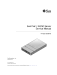
FIGURE 1-1 shows front panel features on the Sun Fire X4170 M2 Server.
FIGURE 1-1
Front Panel Features
Figure Legend
1
Locator LED/Button
6
Product Serial Number (PSN) label and Radio
Frequency Identification (RFID) tag
2
Service Action Required LED (System Level)
7
Power Button
3
DVD Drive ( R/W)
8
Power/OK LED
4
USB ports (2)
9
Service Action Required LEDs (Rear Power Supply,
System Overtemperature, and Top Fan)
5
Disk Configuration Label
1-6
Sun Fire X4170 M2 Server Service Manual • May 2011
1.4
Server Back Panel Features
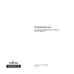
FIGURE 1-2 shows back panel features on the Sun Fire X4170 M2 Server. For more
detailed information about ports and their uses, see the Sun Fire X4170 M2 and X4270
M2 Servers Installation Guide.
FIGURE 1-2
Rear Panel Features
Figure Legend
1
Power Supply Unit (PSU) 0
7
Serial Management Port (SER MGT)
2
Power Supply Unit (PSU) 1
8
Network Management Port (NET MGT)
3
PCIe Slot 0
9
Gigabit Ethernet Ports (0, 1, 2, 3)
4
PCIe Slot 1
10
USB 2.0 Ports (0, 1)
5
PCIe Slot 2
11
HD-15 Video Port
6
Rear Panel System Status LEDs:
Locator LED/Locator button (white)
Service Action Required LED (amber)
Power/OK LED (green)
For a detailed description of PCIe slots, see Section 4.4.2, “PCIe Card Configuration
Guidelines” on page 4-19.
Chapter 1
Sun Fire X4170 M2 Server Overview
1-7
1.5
Server Status Indicators and LEDs
The server provides many status indicators and LEDs to assist you in monitoring and
managing the server.
1-8
■
Section 1.5.1, “Server General Status Indicators” on page 1-9
■
Section 1.5.2, “Server Fan LEDs” on page 1-10
■
Section 1.5.3, “Storage and Boot Drive LEDs” on page 1-11
■
Section 1.5.4, “Power Supply LEDs” on page 1-11
■
Section 1.5.5, “Motherboard LEDs” on page 1-12
Sun Fire X4170 M2 Server Service Manual • May 2011
1.5.1
Server General Status Indicators
There are six system-level indicators, some of which are located on both the server
front panel and the server back panel. These indicators are described in TABLE 1-5.
TABLE 1-5
Server General Status LEDs
Indicator/LED Name
Icon
Color
State Meaning
Power/OK
Green
This LED indicates the operational state of the
chassis. This LED can be in the following states:
• OFF – AC power is not present or the ILOM
boot has not completed.
• STANDY BLINK – Standby power is on, but the
chassis power is off and the ILOM SP is
running.
• SLOW BLINK– Startup sequence has been
initiated on the host. This pattern should begin
soon following powering on the server. This
status indicates either 1)POST diagnostics
running on server host system, or 2) the host is
transitioning from the powered-on state to the
standby state on shutdown.
• STEADY ON – The server is powered on and all
host POST tests have completed. The server is in
one of the following states: 1) the server host is
booting the operating system (OS), 2) the server
host is running the OS.
Service Required
Amber
• OFF – Normal operation
• STEADY ON – Fault present on server. This
indicator lights whenever a fault LED lights for
a server replaceable component.
Note - The lighting of this indicator is always
accompanied by the system console message that
includes a recommended service action.
Locate
White
• OFF – Server is operating normally
• FAST BLINK – Use ILOM to activate this
indicator to enable you to locate a particular
system quickly and easily.
• Pressing the Locate button will toggle LED
FAST BLINK on or off.
Chapter 1
Sun Fire X4170 M2 Server Overview
1-9
TABLE 1-5
Server General Status LEDs (Continued)
Indicator/LED Name
Icon
Color
State Meaning
Top Fan Failure
TOP
FAN
Amber
Indicates that one or more of the internal system
fan modules have failed.
• OFF – Indicates steady state; no service action is
required
• STEADY ON – Indicates service action required;
service the fans.
Rear Power
Supply Failure
REAR
PS
Amber
Indicates that one of the server power supplies has
failed.
• OFF – Indicates steady state; no service action is
required.
• STEADY ON – Indicates service action required;
service the power supply.
Amber
OFF – Normal operation; no service action is
required.
STEADY ON – The system is experiencing an
overtemperature warning condition.
Note - This is a warning indication, not a fatal
overtemperature. Failure to correct this might
result in the system over heating and shutting
down unexpectedly.
Overtemperature
1.5.2
Server Fan LEDs
Each fan module has one bicolored, status LED. The fan LEDs are visible when the
top cover fan door is open. See TABLE 1-6.
TABLE 1-6
1-10
Server Fan Status LEDs
LED Name
Icon
Color
State Meaning
Fan Status
None
Bicolored:
Amber/Green
• Amber – There is a fan fault.
• Green – Fan is properly installed and
functioning correctly. No fan errors
detected.
Sun Fire X4170 M2 Server Service Manual • May 2011
1.5.3
Storage and Boot Drive LEDs
There are three LEDs on each drive. See TABLE 1-7.
TABLE 1-7
LED Name
1.5.4
Server Front Storage Disk LEDs
Icon
Color
State Meaning
Activity
Green
• OFF – Power is off or installed drive is
not recognized by the system.
• STEADY ON – The drive is engaged and
is receiving power.
• STANDBY BLINK – There is disk
activity. LED blinks on and off to
indicate activity.
Service
Required
Amber
• OFF - Normal operation.
• STEADY ON – The system has detected
a fault with the storage drive.
Ready to
Remove
Blue
The storage drive can be removed safely
during a hot-plug operation.
Power Supply LEDs
There are three LEDs on each power supply. These LEDs are visible from the rear of
the server. See TABLE 1-8.
TABLE 1-8
LED Name
Server Power Supply LEDs
Color
State Meaning
DC OK
Green
• STEADY ON – Normal operation. DC output voltage
is within specification.
• OFF: 12V power is disabled.
Service
Required
Amber
• OFF – Normal operation; no service action required.
• STEADY ON – The power supply (PS) has detected a
PS fan failure, PS overtemperature, PS over current, or
PS over/under voltage.
Green
• OFF – No AC power is present.
• STEADY ON – Normal operation. Input power is
above minimum specification.
AC OK
Icon
~AC
Chapter 1
Sun Fire X4170 M2 Server Overview
1-11
1.5.5
Motherboard LEDs
The motherboard contains the several LEDs, which are described in the following
sections:
■
Section 1.5.5.1, “DDR3 DIMM Fault LEDs” on page 1-12
■
Section 1.5.5.2, “CPU Fault LEDs” on page 1-12
■
Section 1.5.5.3, “Fault Remind Super Capacitor Power LED” on page 1-12
■
Section 1.5.5.4, “3.3V_STANDBY OK LED” on page 1-13
Note – A super capacitor provides sufficient power for the motherboard LEDs to be
lit for up to 15 minutes after the removal of the server’s top cover. After 15 minutes,
the capacitor might be discharged enough so that lighting the fault LEDs is not
possible.
1.5.5.1
DDR3 DIMM Fault LEDs
Each of the 18 DDR3 DIMM slots on the motherboard has an amber fault LED
associated with it. If ILOM determines that a DIMM is faulty, pressing the Fault
Remind button on the motherboard signals the service processor to light the fault
LED(s) associated with the faulted DIMM(s).
1.5.5.2
CPU Fault LEDs
The motherboard includes a fault LED adjacent to each of the two CPU sockets.
These LEDs indicate when a CPU is faulty. For example, if on reboot the BIOS detects
that there are uncorrectable CPU errors recorded in the MCA registers apparently left
over from the previous boot, then the BIOS and ILOM work together to record and
diagnose these errors. If it is determined that a CPU is faulty, pressing the Fault
Remind button on the motherboard signals the service processor to light the fault
LED(s) associated with the faulted CPU(s).
1.5.5.3
Fault Remind Super Capacitor Power LED
This LED is located next to the Fault Remind button and is powered from the super
capacitor that powers the fault LEDs on the motherboard. This LED lights to indicate
to the user that the fault remind circuitry is working properly in cases where no
components have failed and, as a result, none of the component fault LEDs
illuminate.
1-12
Sun Fire X4170 M2 Server Service Manual • May 2011
1.5.5.4
3.3V_STANDBY OK LED
The service instructions for all internal components require that all AC power be
removed from the power supplies prior to the server’s top cover being removed. This
green LED is located on the motherboard and it lights to inform a service technician
that the motherboard is receiving standby power from at least one of the power
supplies. This indicator is provided to help prevent service actions on the server’s
internal components while the AC power cords are installed and power is being
supplied to the server.
Chapter 1
Sun Fire X4170 M2 Server Overview
1-13
1-14
Sun Fire X4170 M2 Server Service Manual • May 2011
CHAPTER
2
Preparing to Service the System
This chapter describes how to prepare the server for servicing.
The following topics are covered:
2.1
■
Section 2.1, “Safety Information” on page 2-1
■
Section 2.2, “Required Tools” on page 2-2
■
Section 2.3, “Obtaining the Chassis Serial Number” on page 2-2
■
Section 2.4, “Powering On and Off the Server” on page 2-3
■
Section 2.5, “About the BIOS” on page 2-5
■
Section 2.6, “Extending the Server to the Maintenance Position” on page 2-26
■
Section 2.7, “Removing the Server From the Rack” on page 2-27
■
Section 2.8, “Using Server Filler Panels” on page 2-29
■
Section 2.9, “Performing Electrostatic Discharge and Antistatic Prevention
Measures” on page 2-31
■
Section 2.10, “Removing the Top Cover” on page 2-33
Safety Information
This section describes important safety information that you need to know prior to
removing or installing parts in the Sun Fire X4170 M2 Server.
Caution – Hazardous voltage present. Never attempt to run the server with the top
cover removed.
2-1
Caution – Equipment damage possible. The covers must be in place for proper
airflow.
For your protection, observe the following safety precautions when setting up your
equipment:
2.2
■
Follow all cautions, warnings, and instructions marked on the equipment and
described in the Important Safety Information for Sun Hardware Systems (821-1590).
■
Follow all cautions, warnings, and instructions marked on the equipment and
described in the Sun Fire X4170 M2 and X4270 M2 Servers Safety and Compliance
Guide (821-0490).
■
Ensure that the voltage and frequency of your power source match the voltage
and frequency inscribed on the equipment’s electrical rating label.
■
Follow the electrostatic discharge safety practices as described in this chapter.
Required Tools
The Sun Fire X4170 M2 Server can be serviced with the following tools:
2.3
■
Antistatic wrist strap
■
Antistatic mat
■
4mm Hex wrench
■
No. 2 Phillips screwdriver
■
Straight-edge screwdriver
■
Stylus or pencil (to power the server on and off and press the CLEAR CMOS
button)
Obtaining the Chassis Serial Number
To obtain support for your server, you need your chassis serial number. The chassis
serial number is located on a sticker on the front of the server and on another sticker
on the top of the server.
2-2
Sun Fire X4170 M2 Server Service Manual • May 2011
2.4
Powering On and Off the Server
Refer to the following topics in this section to power on and off a server:
2.4.1
■
Section 2.4.1, “Power On the Server” on page 2-3
■
Section 2.4.2, “Power Off the Server” on page 2-4
■
Section 2.4.3, “Power Off the Server Using the ILOM SP Command-Line Interface”
on page 2-4
Power On the Server
Note – The following procedure assumes that at least one power cord is connected
to the server and power is being supplied to the server’s power supply, and that the
server has been previously powered on according to the installation instructions in
the Sun Fire X4170 M2 and X4270 M2 Servers Installation Guide.
1. Verify that the server is in the standby power state.
In the standby power state, the Power/OK LED on the front panel of the server
blinks (0.1 second on, 2.9 seconds off). The standby power state indicates that the
server SP is active but the server host is powered off.
For the location of the Power/OK LED, see FIGURE 1-1.
2. Apply full power to the server SP and host.
For example:
■
Local server power-on. Press and release the recessed Power button on the
front panel of the server.
For the location of the Power button on the server, see FIGURE 1-1.
■
ILOM SP web interface power-on. Log in to the ILOM web interface for the
server SP and select: Remote Control->Remote Power Control, then
select Power On from the Select Action list box.
■
ILOM SP CLI power on. Log in to the SP ILOM CLI and type: start /SYS
The Power/OK LED illuminates a SLOW BLINK while the system is executing its
BIOS firmware. The Power/OK LED illuminates STEADY ON when the BIOS
firmware completes and the operating system boot begins.
Chapter 2
Preparing to Service the System
2-3
2.4.2
Power Off the Server
To remove main power from the server, use one of the methods shown in the
following table.
TABLE 2-1
Shutdown Procedures
Shutdown
Method
Graceful shutdown
Press and release the Power button on the front panel (FIGURE 1-1). Pressing the
power button causes Advanced Configuration and Power Interface
(ACPI)-enabled operating systems to perform an orderly shutdown of the
operating system. Servers not running ACPI-enabled operating systems will shut
down to standby power mode immediately.
Note - Some operating systems might prompt the user for confirmation of the
shutdown before actually turning off the system.
Emergency shutdown
Press and hold the Power button for at least five seconds until the main power is
off and the server enters standby power mode (FIGURE 1-1).
Caution - All applications and files will be closed abruptly without
saving changes. File system corruption might occur.
ILOM SP CLI shutdown
See Section 2.4.3, “Power Off the Server Using the ILOM SP Command-Line
Interface” on page 2-4.
Caution – To completely power off the server, you must disconnect the AC power cords
from the back panel of the server.
2.4.3
Power Off the Server Using the ILOM SP
Command-Line Interface
You can use the ILOM service processor (SP) to perform a graceful shutdown of the
server and ensure that all of your data is saved and the server is ready for restart.
1. Log in as root. Type:
ssh root@host (Where host is either a hostname, when using DNS, or an
ipaddress.)
Password: root_password (The default password is changeme.)
The ILOM command-line interface (CLI) prompt appears (->).
Depending on the type of problem, you might want to view server status or log
files, or run diagnostics before you shut down the server.
2-4
Sun Fire X4170 M2 Server Service Manual • May 2011
2. Notify affected users that the server will be shut down.
3. Save any open files and quit all running programs.
Refer to your application documentation for specific information.
4. Power down the server. Type:
-> stop /SYS (for a Graceful shutdown as defined in TABLE 2-1)
-> stop -f/SYS (for an Emergency Shut as defined in TABLE 2-1)
For additional information, refer to the Oracle Integrated Lights Out Manager
(ILOM) 3.0 Documentation Collection (formerly called the Sun Integrated Lights Out
Manager).
2.5
About the BIOS
The Basic Input/Output System (BIOS) has a Setup Utility stored in the BIOS flash
memory. The Setup Utility reports system information and can be used to configure
the BIOS settings. The configurable data is provided with context-sensitive help and
is stored in the system's battery-backed CMOS RAM. If the configuration stored in
the CMOS RAM is invalid, the BIOS settings return to their default optimal values.
There are seven menus in the BIOS Setup Utility, which appear in this order: Main,
Advanced, PCI, Boot, Security, Chipset, and Exit. To navigate the menus or options
listed on the menu, use the arrow keys. The options or fields that you can configure
on a menu appear in color. For further instructions on how to navigate and change
settings in the BIOS Setup Utility, refer to the online instructions provided on the
menu.
For additional information about the BIOS operations and menu options available on
your server, refer to the following sections:
■
Section 2.5.1, “BIOS Booting and Setup Considerations” on page 2-6
■
Section 2.5.2, “BIOS Setup Utility Menus” on page 2-12
■
Section 2.5.3, “BIOS Setup Utility Hot Keys” on page 2-14
■
Section 2.5.4, “Accessing the BIOS Setup Utility Menus” on page 2-14
■
Section 2.5.5, “Configuring Support for TPM” on page 2-17
■
Section 2.5.6, “Configuring SP LAN Settings” on page 2-22
■
Section 2.5.7, “Configuring Option ROM Settings in BIOS” on page 2-24
■
Section 2.5.8, “Updating the BIOS Firmware” on page 2-26
Chapter 2
Preparing to Service the System
2-5
2.5.1
BIOS Booting and Setup Considerations
Refer to the following sections for information when booting the BIOS and other
set up considerations:
2.5.1.1
■
Section 2.5.1.1, “Default BIOS Power-On Self-Test (POST) Events” on page 2-6
■
Section 2.5.1.2, “BIOS POST F1 and F2 Errors” on page 2-7
■
Section 2.5.1.3, “How BIOS POST Memory Testing Works” on page 2-10
■
Section 2.5.1.4, “Ethernet Port Device and Driver Naming” on page 2-11
■
Section 2.5.1.5, “Ethernet Port Booting Priority” on page 2-12
■
Section 2.5.1.6, “Hardware Prefetchers” on page 2-12
Default BIOS Power-On Self-Test (POST) Events
At system startup, the BIOS performs a power-on self-test that checks the hardware
on your server to ensure that all components are present and functioning properly.
TABLE 2-2 identifies the events that can occur during BIOS POST, as well as specifies
whether these events can prevent the host from powering-on.
TABLE 2-2
BIOS POST Events
Event
Cause
Boot continues
on host?
User password violation
Attempt to enter password fails three times
No
Setup password violation
Attempt to enter password fails three times
No
Correctable ECC
Memory Correctable ECC (error correction code) error
detected
Does not
apply
Uncorrectable ECC
Memory Uncorrectable ECC error detected
Does not
apply
No system memory
No physical memory detected in the system
No
No usable system memory
All installed memory has experienced an unrecoverable
failure
No
Hard disk controller failure
No disk controller found
Yes
Keyboard failure
Keyboard cannot be initialized
Yes
Boot media failure
No removable boot media is found
Yes
No video device
No video controller is found
No
Firmware (BIOS) ROM corruption
BIOS checksum fails and the boot block is not
corrupted
No
System restart
System boot initiated
Yes
2-6
Sun Fire X4170 M2 Server Service Manual • May 2011
TABLE 2-2
BIOS POST Events (Continued)
Event
Cause
Boot continues
on host?
Initiated by hard reset
Boot process started by hard reset
Yes
Memory initialization
Memory sizing is occurring
System firmware progress
Does not
apply
Primary processor initialization
Primary CPU initialization
System firmware progress
Does not
apply
Initiated by warm reset
Boot process started by warm reset
Does not
apply
Embedded controller management
Management controller initialization
Does not
apply
Secondary processor(s) initialization
Secondary CPU initialization asserted
System firmware progress
Does not
apply
Video initialization
When BIOS initializes keyboard
Does not
apply
Keyboard controller initialization
When BIOS initializes keyboard
Does not
apply
Option ROM initialization
BIOS initializes Option ROMs
System firmware progress
Does not
apply
Option ROM space exhausted
BIOS cannot copy an option to the memory
Yes
User initiated system set up
User initiated access to BIOS Setup Utility
System firmware progress
Does not
apply
User initiated boot to OS
System boot initiated
System firmware progress
Does not
apply
No bootable media
Nothing to boot from
No
PXE server not found
Boot error - PXE server not found
F12 key was pressed but BIOS fails to boot from PXE
server
No
ACPI Power state
Soft-off power applied
Does not
apply
2.5.1.2
BIOS POST F1 and F2 Errors
Each power-on-self-test (POST) diagnostic is a low-level test designed to pinpoint
faults in a specific hardware component. If the POST diagnostic discloses an F1 or F2
error, it typically reports the following information about the error:
■
Type of error detected
Chapter 2
Preparing to Service the System
2-7
■
When or where the error occurred
TABLE 2-3 lists some of the F1 and F2 error messages that could appear during the
POST diagnostics along with instructions for how to possibly resolve the error
reported.
TABLE 2-3
BIOS POST F1 and F2 Error Messages
BIOS POST Error Message
Error Type
Resolution
Uncorrectable Error Detected on Last
Boot:IOH(0) Protocol Error (Please Check SP Log
for more Details)
IOH error
• Press F1 to continue.
• Check the SP event log in ILOM for more
details.
Uncorrectable Error Detected on Last
Boot:IOH(0) QPI [x] Error (Please Check SP Log
for more Details)
IOH error
• Press F1 to continue.
• Check the fault management function and
the SP event log in ILOM for more details.
Note - Where QPI [x] equals 0 for QPI Link 0
or 1 for QPI Link 1.
Uncorrectable Error Detected on Last
Boot:IOH(0) PCI-E [x] Error (Please Check SP
Log for more Details)
IOH error
• Press F1 to continue.
• Check the fault management function and
the SP event log in ILOM for more details.
Note - Where PCI-E [x] port number can
range from 1 to 10 depending on the PCI root
port on IOH.
Uncorrectable Error Detected on Last
Boot:IOH(0) ESI Error (Please Check SP Log for
more Details)
IOH error
• Press F1 to continue.
• Check the fault management function and
the SP event log in ILOM for more details.
Uncorrectable Error Detected on Last
Boot:IOH(0) Thermal Error (Please Check SP
Log for more Details)
IOH error
• Press F1 to continue.
• Check the fault management function and
the SP event log in ILOM for more details.
Uncorrectable Error Detected on Last
Boot:IOH(0) DMA Error (Please Check SP Log
for more Details)
IOH error
• Press F1 to continue.
• Check the SP event log for more details.
Uncorrectable Error Detected on Last
Boot:IOH(0) Miscellaneous Error (Please Check
SP Log for more Details)
IOH error
• Press F1 to continue.
• Check the fault management function and
the SP event log in ILOM for more details.
Uncorrectable Error Detected on Last
Boot:IOH(0) VTd Error (Please Check SP Log for
more Details)
IOH error
• Press F1 to continue.
• Check the SP event log in ILOM for more
details.
BMC Not Responding
ILOM error
• Press F1 to continue.
Note - This error message might display if
during the SP/BIOS communication an
internal error occurs. This error might require
you to restart the SP.
2-8
Sun Fire X4170 M2 Server Service Manual • May 2011
TABLE 2-3
BIOS POST F1 and F2 Error Messages (Continued)
BIOS POST Error Message
Error Type
Resolution
•
•
•
•
IDE/ATAPI
error
• Press F1 to continue.
• Check the SP event log in ILOM for more
details.
Note - These type of error messages are
displayed when the BIOS is attempting to
configure IDE/ATAPI devices in POST.
Timer Error
8254 timer
error
• Press F1 to continue.
• Check the SP event log in ILOM for more
details.
Note - This type of error typically indicates
an error while programming the count
register of channel 2 of the 8254 timer. This
could indicate a problem with system
hardware.
RAM R/W test failed
Memory test
failure
• Press F1 to continue.
• Check the SP event log in ILOM for more
details.
Note - This type of error typically indicates
that the RAM read/write test failed.
KBC BAT Test failed
Keyboard
controller
basic
assurance test
error
• Press F1 to continue.
• Check the SP event log in ILOM for more
details.
Note - Keyboard controller BAT test failed.
This error might indicate a problem with
keyboard controller initialization.
Display memory test failed
Video display • Press F1 to continue.
error
• Check the SP event log in ILOM for more
details.
CMOS Battery Low
CMOS
battery error
• Press F2 to enter BIOS Setup Utility to load
system defaults.
• Check the SP event log in ILOM for more
details.
• If necessary, replace CMOS battery.
• CMOS Checksum Bad
• CMOS Date/Time Not Set
CMOS error
• Press F2 to enter BIOS Setup Utility to load
system defaults.
• Check the SP event log in ILOM for more
details.
Primary Slave Hard Disk Error
Primary Master Hard Disk Error
Secondary Master Hard Disk Error
Secondary Slave Hard Disk Error
Chapter 2
Preparing to Service the System
2-9
TABLE 2-3
BIOS POST F1 and F2 Error Messages (Continued)
BIOS POST Error Message
Error Type
Resolution
Password check failed
Password
check error
• Press F1 to continue.
• Check the SP event log in ILOM for more
details.
Note - This type of error indicates that the
password entered does not match the
password specified in the BIOS Setup Utility.
This condition might occur for both
Supervisor and User password verification.
Keyboard/Interface Error
Keyboard
controller
error
• Press F1 to continue.
• Check the SP event log in ILOM for more
details.
Note - This type of error indicates that the
Keyboard Controller failure. This error might
indicate a problem with system hardware.
S.M.A.R.T error on the drive
S.M.A.R.T
device error
• Press F1 to continue.
• Check the SP event log in ILOM for more
details.
Note - Self-Monitoring, Analysis, and
Reporting Technology (S.M.A.R.T.) failure
messages might indicate the need to replace
the storage device.
2.5.1.3
How BIOS POST Memory Testing Works
The BIOS POST memory testing is performed as follows:
1. The first megabyte of DRAM is tested by the BIOS before the BIOS code is copied
from ROM to DRAM.
2. After exiting out of DRAM, the BIOS performs a simple memory test (where a
write/read of every location with the pattern 55aa55aa is performed).
Note – The simple memory test is performed only if Quick Boot is not enabled from
the Boot Settings Configuration screen. Enabling Quick Boot causes the BIOS to skip
the memory test.
3. The BIOS polls the memory controllers for both correctable and non-correctable
memory errors and logs those errors into the SP.
4. The message, BMC Responding, appears at the end of POST.
2-10
Sun Fire X4170 M2 Server Service Manual • May 2011
2.5.1.4
Ethernet Port Device and Driver Naming
The server supports four 10/100/1000BASE-T Gigabit Ethernet ports on the rear of
the chassis. For port locations, see FIGURE 1-2.
The device naming for the Ethernet interfaces is reported differently by different
interfaces and operating systems. See TABLE 2-4 for the physical (BIOS) and logical
(operating system) naming conventions used for each interface.
TABLE 2-4
Logical Port Naming
Interface
NET0
NET1
NET2
NET3
BIOS
slot 108
slot 109
slot 110
slot 111
Solaris 10 10/09
igb0
igb1
igb2
igb3
RHEL 5.4 (64-bit) eth0*
eth1
eth2
eth3
Oracle Enterprise
Linux (OEL) 5.4
(64-bit)
eth0†
eth1
eth2
eth3
SLES 10 SP3
(64-bit) and
SLES 11 (64-bit)
eth0‡
eth1
eth2
eth3
Windows 2008
net1
net2
net3
net4
Oracle VM 2.2.1
xenbr0
xenbr1
xenbr2
xenbr3
VMware ESX 4.0
and ESXi 4.0
vmnic#**
vmnic#
vmnic#
vmnic#
* If you are using the XEN kernel in RHEl 5, there will be XEN bridge devices associated with each logical
port. The ports for these bridge devices will be named xenbrn, where n is 0-3.
† If you are using the XEN kernel in OEL 5, there will be XEN bridge devices associated with each logical
port. The ports for these bridge devices will be named xenbrn, where n is 0-3.
‡ If you are using the XEN kernel in SLES 10 or SLES 11, there will be XEN bridge devices associated with
each logical port. The ports for these bridge devices will be named xenbrn, where n is 0-3.
** For VMware, the Ethernet port that the user assigns to the service console will be vmnic0. Other ports are
mapped by ascending order of the PCI bus enumerations.
Chapter 2
Preparing to Service the System
2-11
2.5.1.5
Ethernet Port Booting Priority
The order in which the BIOS detects the Ethernet ports during boot time, and the
corresponding drivers that control those ports, are listed below:
1. NET 0 (INTEL NIC 0)
2. NET 1 (INTEL NIC 1)
3. NET 2 (INTEL NIC 2)
4. NET 3 (INTEL NIC 3)
2.5.1.6
Hardware Prefetchers
Hardware prefetchers work well in workloads that traverse array and other regular
data structures. The hardware prefetcher option is disabled by default and should be
disabled when running applications that perform aggressive software prefetching or
for workloads with limited cache. For example, memory-intensive applications with
high bus utilization could see a performance degradation if hardware prefetching is
enabled.
2.5.2
BIOS Setup Utility Menus
TABLE 2-5 provides descriptions for the seven top-level BIOS setup menus.
TABLE 2-5
BIOS Setup Menus Summary
Menu
Description
Main
General product information, including BIOS type, processor, memory,
and time/date.
Advanced
Configuration information for the CPU, memory, IDE, Super IO, trusted
computing, USB, PCI, MPS and other information.
PCI
Configure the server to clear NVRAM during system boot.
Boot
Configure the boot device priority (storage drives and the DVD-ROM
drive).
Security
Set or change the user and supervisor passwords.
Chipset
View the configuration of server chipsets.
Exit
Save changes and exit, discard changes and exit, discard changes, or
load optimal or fail-safe defaults.
See Section C.2, “BIOS Setup Utility Menu Screens” on page C-3 for examples of each
of these screens.
2-12
Sun Fire X4170 M2 Server Service Manual • May 2011
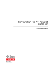
FIGURE 2-1 identifies the sub-menus that you can access from each of the seven
top-level BIOS menus.
FIGURE 2-1
BIOS Configuration Utility Menu Tree
For an example of the options that are available on the BIOS Setup Utility menus, see
Appendix C.
Chapter 2
Preparing to Service the System
2-13
2.5.3
BIOS Setup Utility Hot Keys
TABLE 2-6 provides a description of the BIOS Setup Utility ILOM Remote Console
keys and the corresponding serial connection key combinations.
TABLE 2-6
BIOS Setup Utility ILOM Remote Console Keys and the Corresponding Serial
Connection Key Combinations
ILOM Remote
Console Keys
Serial Connection Hot Key
Combinations
F1
Ctrl+Q (Press and hold the Access the BIOS Setup Utility if there is an
error during the boot process
Control key and type Q)
F2
Ctrl+E
Enter BIOS Setup Utility while the system
is performing the power-on self test (POST)
F7
Ctrl+D
Discard changes, but do not exit
F8
Ctrl+P
Select the BBS Popup menu, which allows
you to select a boot device
F9
Ctrl+O
Load optimal BIOS defaults
F10*
Ctrl+S
Save changes and exit
F12
Ctrl+N
Boot the server from the network (PXE
boot)
Function
* F10 is not supported on the ILOM Remote Console; instead, use the arrow keys to navigate to the Exit menu and
press Enter.
2.5.4
Accessing the BIOS Setup Utility Menus
You can access BIOS Setup Utility screens from the following interfaces:
■
Use a USB keyboard, mouse, and VGA monitor connected directly to the server.
■
Use a terminal (or terminal emulator connected to a computer) through the serial
port on the back panel of the server.
■
Connect to the server using the ILOM Remote Console.
The following procedure describes the steps for accessing the BIOS Setup Utility
menus.
2.5.4.1
Access BIOS Setup Utility Menus
1. Power-on or power-cycle the server.
The Boot Option screen appears (FIGURE 2-2).
2-14
Sun Fire X4170 M2 Server Service Manual • May 2011
FIGURE 2-2
Boot Option Screen
2. To enter the BIOS Setup Utility, do the following:
a. Wait for the last line of the screen output to change to Initializing USB
Controllers..Done
This will take several seconds.
b. When Done appears, immediately press the F2 key.
Note – If there is an error during the boot process, you can press F1 to access the
BIOS Setup Utility.
The BIOS Setup Utility dialog appears (FIGURE 2-3).
Chapter 2
Preparing to Service the System
2-15
FIGURE 2-3
BIOS Setup Utility: Main – System Overview
3. Use the left and right arrow keys to select the different menu options.
4. As you select each menu option, the top-level screen for that menu option
appears.
5. To select an option on a top-level screen, use the up and down arrow keys to
scroll up and down the options presented.
Only options that can be modified are highlighted when you press the up and
down arrow keys.
■
If a field can be modified, as you select the option, user instructions for
modifying the option appear in the right column of the screen.
■
If a field is a link to a sub-screen, an instruction to press the Enter key to access
the sub-screen appears in the right column.
6. Modify the setup field and press the Esc key to save the changes and exit the
screen.
Some screens present a confirmation dialog box that enables unwanted changes to
be retracted.
7. On sub-screens that only provide configuration information and cannot be
modified, press the Esc key to exit the screen.
8. To continue modifying other setup parameters, repeat Step 3 through Step 7.
Otherwise, go to Step 9.
2-16
Sun Fire X4170 M2 Server Service Manual • May 2011
9. Press and release the right arrow key until the Exit menu screen appears.
10. Follow the instructions on the Exit menu screen to save or discard your changes
and exit the BIOS Setup Utility.
2.5.5
Configuring Support for TPM
If you intend to use the Trusted Platform Module (TPM) feature set that is provided
in Windows 2008, you must configure the server to support this feature.
TPM enables you to administer the TPM security hardware in your server. For
additional information about implementing this feature, refer to the Windows
Trusted Platform Module Management documentation provided by Microsoft.
2.5.5.1
Configure TPM Support in BIOS
1. Access the BIOS Setup Utility menus.
For instructions, see Section 2.5.4.1, “Access BIOS Setup Utility Menus” on
page 2-14.
When BIOS is started, the main BIOS Setup Utility top-level System Overview
screen appears (FIGURE 2-4).
FIGURE 2-4
Main - System Overview Screen
Chapter 2
Preparing to Service the System
2-17
2. In the BIOS Setup Utility screen, select the Advanced menu option.
The Advanced Settings screen appears (FIGURE 2-5).
FIGURE 2-5
Advanced Settings Screen
3. In the Advanced Settings screen, select Trusted Computing and press Enter.
The Trusted Computing screen appears (FIGURE 2-6).
2-18
Sun Fire X4170 M2 Server Service Manual • May 2011
FIGURE 2-6
Trusted Computing Screen
4. In the Trusted Computing screen, select the TCG/TPM Support.
A pop-up dialog box appears.
5. In the pop-up dialog box, set the TCG/TPM Support option to Yes and click Ok.
Note – Even if the TCG/TPM Support was already set to Yes in the dialog shown
above, continue on and complete the remaining steps of this procedure to ensure that
all TPM configuration requirements are satisfied.
The updated Trusted Computing dialog appears and shows that the TCG/TPM
Support setting has changed to Yes (FIGURE 2-7).
Chapter 2
Preparing to Service the System
2-19
FIGURE 2-7
Trusted Computing Screen Showing TCG/TPM Support Enabled
Note – In the above screen, the Execute TPM Command setting shows the default,
Don’t Change.
6. In the Trusted Computing screen, select the Execute TPM Command option
setting.
A pop-up dialog box appears.
7. In the pop-up dialog box, set the Execute TPM Command option to Enabled and
click Ok.
The updated Trusted Computing screen appears and shows that the Execute TPM
Command setting has changed to Enabled (FIGURE 2-8).
2-20
Sun Fire X4170 M2 Server Service Manual • May 2011
FIGURE 2-8
Execute TPM Command Setting Enabled
8. Press F10 to save the changes and exit BIOS.
9. To verify that TPM support is configured, do the following:
a. Reboot the server.
b. To enter the BIOS Setup Utility, press the F2 key while the system is
performing the power-on self-test (POST).
When BIOS is started, the main BIOS Setup utility top-level screen appears
(FIGURE 2-4).
c. Select Advanced --> Trusted Computing and press Enter.
The updated Trusted Computing screen appears (FIGURE 2-9).
Confirm that the TCG/TPM Support setting is set to Yes and the TPM
Enabled/Disable Status is set to Enabled.
Chapter 2
Preparing to Service the System
2-21
FIGURE 2-9
Updated TPM Enabled/Disabled Setting
10. Press F10 to exit BIOS.
This completes the TPM configuration.
2.5.6
Configuring SP LAN Settings
You can assign an IP address for the server SP from the BIOS Setup Utility on the
IPMI LAN configuration menu. Alternatively, you can also specify the LAN settings
for the SP using ILOM. For instructions for setting the IP address in ILOM, see the
ILOM Documentation Collection.
For instructions on configuring SP LAN settings using the BIOS Setup Utility, see the
following sections:
2.5.6.1
■
Section 2.5.6.1, “Configure LAN Settings for SP” on page 2-23
■
Section 2.5.6.2, “Viewing or Setting the ILOM SP IP Address Using the BIOS Setup
Utility” on page 2-24
Configure LAN Settings for SP
1. Access the BIOS Setup Utility menus.
For instructions, see Section 2.5.4.1, “Access BIOS Setup Utility Menus” on
page 2-14.
2-22
Sun Fire X4170 M2 Server Service Manual • May 2011
2. In the BIOS Setup Utility menus, use the arrow keys (or Tab key) to navigate to
the Advanced menu.
3. In the Advanced menu, select IPMI Configuration.
4. In the IPMI Configuration menu, select LAN Confutation.
The LAN Configuration screen appears (FIGURE 2-10).
FIGURE 2-10
BIOS Setup Utility: Advanced – LAN Configuration
5. In the LAN Configuration screen, use the arrow keys to select and specify the
appropriate LAN configuration settings.
6. Press F10 to save the changes and exit BIOS.
Chapter 2
Preparing to Service the System
2-23
2.5.6.2
Viewing or Setting the ILOM SP IP Address Using the BIOS
Setup Utility
1. Power on the server (or restart the server if it is running).
2. When the BIOS splash screen or text prompt appears during the power-on
self-test (POST) operation, press F2 to access the BIOS Setup Utility.
3. Using the left and right arrow keys on the keyboard, navigate to the Advanced
tab.
The Advanced Settings screen appears (FIGURE 2-5).
4. Using the up and down arrow keys, select the IPMI Configuration option
and press Enter to go to the subscreen.
The IPMI Configuration subscreen appears.
5. Using the up and down arrow keys, select the Set LAN Configuration option
and press Enter.
The LAN Configuration subscreen appears and shows the current ILOM SP IP
address.
6. To set the IP address:
a. Select Set LAN Configuration, then use the arrow keys to select settings.
b. Specify the appropriate settings, then proceed to Step 7.
7. Select Commit and press Enter.
8. Allow about five seconds for the Commit to complete, then select Refresh and
press Enter.
9. Select Refresh a second time and press Enter to confirm that the IP address
information has been set.
10. Press F10 to save any changes you made and to exit the BIOS Setup Utility.
2.5.7
Configuring Option ROM Settings in BIOS
The BIOS Option ROM is 128 Kbytes. Of these 128 Kbytes, approximately 80 Kbytes
are used by the VGA controller, the disk controller, and the network interface card.
Approximately 48 Kbytes remain to be shared by the Option ROMs on all bootable
PCI-Express plug-in cards.
2-24
Sun Fire X4170 M2 Server Service Manual • May 2011
2.5.7.1
Enable or Disable Option ROM Settings
1. Access the BIOS Setup Utility menus.
For instructions, see Section 2.5.4.1, “Access BIOS Setup Utility Menus” on
page 2-14.
2. In the BIOS Setup Utility menus, use the arrow keys (or Tab key) to navigate to
the Boot menu.
The Boot menu appears (FIGURE 2-11).
FIGURE 2-11
BIOS Setup Utility: Boot - Option ROM Configuration
3. In the Boot menu listing the Option ROM settings, highlight the applicable
Option ROM setting to modify, then press Enter.
A dialog box appears listing the available settings.
4. In the dialog box, do one of the following:
■
Select Enabled to enable the Option ROM setting.
■
Select Disabled to disable the Option ROM setting.
5. Press F10 to save the changes and exit BIOS.
Chapter 2
Preparing to Service the System
2-25
2.5.8
Updating the BIOS Firmware
The BIOS firmware is updated whenever you update the ILOM SP firmware. For
instructions about updating the firmware, refer to the ILOM Documentation
Collection.
2.6
Extending the Server to the Maintenance
Position
The following components can be serviced with the server in the maintenance
position:
■
Storage drives
■
Fan modules
■
Power supplies
■
DVD/USB module
■
Fan board
■
DDR3 DIMMs
■
PCIe Risers
■
PCIe cards
■
Motherboard battery
If the server is installed in a rack with extendable slide rails, use this procedure to
extend the server to the maintenance position.
2.6.1
Extend Server to the Maintenance Position
1. Verify that no cables will be damaged or will interfere when the server is
extended.
Although the cable management arm (CMA) that is supplied with the server is
hinged to accommodate extending the server, you should ensure that all cables
and cords are capable of extending.
2. From the front of the server, release the two slide release latches (FIGURE 2-12).
Squeeze the green slide release latches to release the slide rails.
2-26
Sun Fire X4170 M2 Server Service Manual • May 2011
FIGURE 2-12
Slide Release Latches
3. While squeezing the slide release latches, slowly pull the server forward until
the slide rails latch.
The server is now in the extended maintenance position.
2.7
Removing the Server From the Rack
The server must be removed from the rack to service the following components:
■
Motherboard
■
CPUs
■
Power distribution board
■
Paddle board
■
Storage drive cage
■
Disk backplane
■
Front panel light-pipe assemblies
Chapter 2
Preparing to Service the System
2-27
2.7.1
Remove Server From the Rack
Caution – The server weighs 36 lb (16.36 kg). If necessary, use two people to
dismount and carry the chassis.
1. Disconnect all the cables and power cords from the server.
2. Extend the server to the maintenance position.
See Section 2.6.1, “Extend Server to the Maintenance Position” on page 2-26.
3. Press the metal lever that is located on the inner side of the rail to disconnect
the cable management arm (CMA) from the rail assembly (FIGURE 2-13).
The CMA is still attached to the cabinet, but the server chassis is now
disconnected from the CMA.
FIGURE 2-13
Metal Lever and Cable Management Arm
4. From the front of the server, pull the release tabs forward and pull the server
forward until it is free of the rack rails (FIGURE 2-14).
A release tab is located on each rail.
2-28
Sun Fire X4170 M2 Server Service Manual • May 2011
FIGURE 2-14
Release Tabs on Slide Assembly
5. Set the server on a sturdy work surface.
2.8
Using Server Filler Panels
Each server is shipped with module-replacement filler panels for CPUs, storage
drives, DDR3 memory modules (DDR3 DIMMs), PCIe cards, and power supplies.
These filler panels are installed at the factory and must remain in the server until you
replace them with a purchased option.
As needed, consult the following sections when removing and replacing a server
component:
2.8.1
■
Section 2.8.1, “Filler Panel Purpose” on page 2-29
■
Section 2.8.2, “Filler Panel Removal and Installation” on page 2-30
Filler Panel Purpose
A filler panel is an empty metal or plastic enclosure that does not contain any
functioning system hardware or cable connectors. These panels must remain in any
unused module slots (CPU, storage drives, DDR3 DIMMs, PCIe cards, power
Chapter 2
Preparing to Service the System
2-29
supplies) to ensure proper airflow throughout the system. If you remove a filler
panel and continue to operate your system with an empty module slot, the operating
performance of your system could decline.
2.8.2
Filler Panel Removal and Installation
Before you can install a optional server component into the server, you must remove
the filler panel from the location into which you intend to install the component.
When you remove a CPU, storage drive, DDR3 DIMM, PCIe card, or a power supply
from the server, you must install either a replacement for component removed or a
filler panel.
TABLE 2-7 describes how to remove and install server filler panels.
TABLE 2-7
Server Filler Panel Removal and Installation Procedures
Filler Panel Type
Removal Procedure
Install Procedure
DDR3 DIMM
1. Locate the DDR3 DIMM filler panel to
1. Locate the vacant DDR3 DIMM slot on the
be removed from the motherboard.
motherboard.
2. Simultaneously press down on both
2. Ensure that ejector levers at both ends of the
ejector levers at the ends of the memory
DDR3 DIMM slot are in a fully opened
module slot.
position.
3. Lift the filler panel straight up to remove 3. Align the filler panel with the empty slot,
it from the memory module socket.
then gently press the filler panel into the slot
until both ejector levers close, locking the
filler panel in place.
CPU
Note - CPUs
should only be
removed or
installed by
Oracle qualified
service
personnel.
1. Ensure that the CPU socket release lever and
1. To remove the CPU filler panel in the
socket, pull the release lever away from
bail are in a fully opened position.
the socket into a fully opened position. 2. Gently insert the filler panel onto the exposed
pins in the CPU socket.
2. Lift the bail and then gently lift the filler
panel straight up and out of the CPU
3. After the filler panel is fully seated in the
socket.
socket, close the bail onto the top of the filler
panel, then pivot the release lever down and
into the locked position at the side of the
socket.
2-30
Sun Fire X4170 M2 Server Service Manual • May 2011
TABLE 2-7
Server Filler Panel Removal and Installation Procedures (Continued)
Filler Panel Type
Removal Procedure
Install Procedure
Storage Drive
1. Locate the disk drive filler panel to be
1. Locate the vacant disk drive module slot in
removed from the server.
the server, then ensure that the release lever
on the filler panel is fully opened.
2. To unlatch the disk drive filler panel,
press the release lever button then tilt
2. Slide the filler panel into the vacant slot by
the lever up into a fully opened position.
pressing the middle of the filler panel
faceplate with your thumb or finger.
3. To remove the filler panel from the slot,
hold the opened release lever and gently
The release lever will lower as it makes
slide the filler panel toward you.
contact with the chassis. Do not slide the
filler panel in all the way. Leave the filler
panel out approximately 0.25 to 0.50 inch (6
to 12 mm) from the opening
3. Using your thumb or finger, press on the
middle of the filler panel faceplate until the
release lever engages with the chassis.
4. Close the release lever until it clicks into
place and is flush with the front of the server.
PCI Slot
1. Remove the server top cover.
1. Remove the server top cover.
2. Remove the PCI slot filler panel from the 2. Press the PCI filler panel into the vacant PCI
location into which you intend to install
slot.
the PCIe card.
Power supply
1. To release the filler panel side latches,
use your fingers to press and hold both
sides of the filler panel away from the
sides of the power supply bay.
2. Using fingers on your other hand, grasp
the lip at the bottom of the filler panel
and pull it out of the power supply bay.
2.9
Performing Electrostatic Discharge and
Antistatic Prevention Measures
2.9.1
Electrostatic Discharge Safety Measures
1. Position the filler panel in the power supply
bay so that the closed end is facing inward
and the lip that is used to remove the filler
panel is in the bottom position.
2. Press the filler panel into the power supply
bay until it is flush with the power supply
bay.
Electrostatic discharge (ESD) sensitive devices, such as the motherboards, PCIe cards,
storage drives, and memory cards, require special handling.
Chapter 2
Preparing to Service the System
2-31
Caution – Circuit boards and storage drives contain electronic components that are
extremely sensitive to static electricity. Ordinary amounts of static electricity from
clothing or the work environment can destroy the components located on these
boards and drives. Do not touch the components along their connector edges.
Caution – You must disconnect both power supplies before servicing any of the
components documented in this chapter.
2.9.1.1
Using an Antistatic Wrist Strap
Wear an antistatic wrist strap and use an antistatic mat when handling components
such as storage drive assemblies, circuit boards, or PCIe cards. When servicing or
removing server components, attach an antistatic strap to your wrist and then to a
metal area on the chassis. Following this practice equalizes the electrical potentials
between you and the server.
Note – An antistatic wrist strap is not included in the Accessory Kit for the Sun Fire
X4170 M2 Server. However, antistatic wrist straps are still included with options and
components.
2.9.1.2
Using an Antistatic Mat
Place ESD-sensitive components on an antistatic mat.
2.9.2
Using ESD Handling Precautions
1. Prepare an antistatic surface to set parts on during the removal, installation, or
replacement process.
Place ESD-sensitive components such as the printed circuit boards on an antistatic
mat. The following items can be used as an antistatic mat:
2-32
■
Antistatic bag used to wrap an Oracle replacement part
■
Oracle ESD mat, part number 250-1088
■
A disposable ESD mat (shipped with some replacement parts or optional
system components)
Sun Fire X4170 M2 Server Service Manual • May 2011
2. Attach an antistatic wrist strap.
When servicing or removing server components, attach an antistatic strap to your
wrist and then to a metal area on the chassis.
2.10
Removing the Top Cover
The top cover and fan door are integrated.
Caution – If the top cover is removed without first removing the AC power cords,
then not only will the server host shut down, but also this condition will be flagged
as a system fault (that is, the fault LEDs will light). In this situation, the SP will need
to be power-cycled (remove/reinsert AC power cords) before the server can be
properly returned to service.
Note – Servicing some components requires that the top cover be removed.
2.10.1
Remove Top Cover
1. Ensure that the AC power cords are disconnected from the server power
supplies.
2. Unlatch the fan module door (FIGURE 2-15 [1]).
Pull the two release tabs back to release the door. Rotate the fan door to the open
position and hold it there.
Chapter 2
Preparing to Service the System
2-33
FIGURE 2-15
Removing the Top Cover
3. Press the top cover release button and slide the top cover toward the rear of the
server about a 0.5 inches (12.7 mm) [2].
4. Lift up and remove the top cover [3].
2-34
Sun Fire X4170 M2 Server Service Manual • May 2011
CHAPTER
3
Servicing Customer-Replaceable
Devices
This chapter describes how to replace the hot-swappable and hot-pluggable
customer-replaceable units (CRUs) in the Sun Fire X4170 M2 Server.
The following topics are covered in this section:
3.1
■
Section 3.1, “Hot-Pluggable Versus Hot-Swappable Devices” on page 3-1
■
Section 3.2, “Servicing Storage Drives” on page 3-2
■
Section 3.3, “Servicing Fan Modules” on page 3-7
■
Section 3.4, “Servicing Power Supplies” on page 3-12
Hot-Pluggable Versus Hot-Swappable
Devices
Devices that are hot-pluggable, unlike hot-swappable devices, require actions in
addition to physical removal and replacement.
3.1.1
Hot-Pluggable Devices
Hot-pluggable devices are those devices that you can remove and install while the
server is running. However, you must perform one or more administrative tasks
before and/or after installing the hardware (for example, mounting a storage drive).
3-1
In the Sun Fire X4170 M2 Server, storage drives are hot-pluggable. To hot-plug a
drive you must take the drive offline (to prevent any applications from accessing it
and to remove the logical software links to it) before you can safely remove it. See
Section 3.2, “Servicing Storage Drives” on page 3-2.
3.1.2
Hot-Swappable Devices
Hot-swappable devices are those devices that can be removed and installed while the
server is running without requiring any administrative tasks (for example, fan
modules and power supplies).
In the Sun Fire X4170 M2 Server, the following devices are hot-swappable:
■
Fan modules. See Section 3.3, “Servicing Fan Modules” on page 3-7.
■
Power supplies. See Section 3.4, “Servicing Power Supplies” on page 3-12.
Note – The chassis-mounted storage drives can be hot-swappable, depending on
how they are configured. See Section 3.2, “Servicing Storage Drives” on page 3-2.
3.2
Servicing Storage Drives
The following topics are covered in this section:
3.2.1
■
Section 3.2.1, “Server Storage Drive Locations” on page 3-2
■
Section 3.2.2, “Storage Drive Status LED Reference” on page 3-3
■
Section 3.2.3, “Remove Storage Drive” on page 3-4
■
Section 3.2.4, “Install Storage Drive” on page 3-5
Server Storage Drive Locations
FIGURE 3-1 shows the physical drive locations for a Sun Fire X4170 M2 Server with eight
2.5-inch hard disk drives.
3-2
Sun Fire X4170 M2 Server Service Manual • May 2011
FIGURE 3-1
Storage Drive Locations
Figure Legend
HDD1
HDD3
HDD5
DVD drive and USB Connectors (2)
HDD0
HDD2
HDD4
HDD6
3.2.2
HDD7
Storage Drive Status LED Reference
FIGURE 3-2 shows the storage drive status LEDs.
FIGURE 3-2
Storage Drive Status LEDs
TABLE 3-1
Storage Drive Status LED Descriptions
Legend
LED
Symbol
Color
Lights When...
1
OK to Remove
Blue
The storage drive can be removed
safely during a hot-plug operation.
2
Service Action Required
Amber
The system is running and the
storage drive is faulty. The front and
rear panel Service Action Required
LEDs are also lit if the system detects
a storage drive fault.
3
OK/Activity
Green
Data is being read from or written to
the storage drive.
Chapter 3
Servicing Customer-Replaceable Devices
3-3
3.2.3
Remove Storage Drive
Storage drives can be hot-plugged or cold-plugged (removed when power is off).
Storage drives in the server might be hot-pluggable, depending on the storage drive
configuration.
To hot-plug a drive, you must take the drive offline (to prevent any applications from
accessing it, and to remove the logical software links to it) before you can safely
remove it.
1. Identify the storage drive you wish to remove.
The amber Service Action Required LED might be lit. For specific drive locations,
see Section 3.2.1, “Server Storage Drive Locations” on page 3-2.
2. Determine whether the storage drive can be hot-plugged or cold-plugged.
The following conditions might prevent you from hot-plugging a drive. You must
power off the server, if the storage drive:
■
Contains the operating system, and the operating system is not mirrored on
another drive.
■
Cannot be logically isolated from the online operations of the server.
3. Do one of the following:
■
To hot-plug a drive, unconfigure the storage drive, as required.
You must take the drive offline before you can safely remove it. This removes
the logical software links to the drive and prevents any applications from
accessing it. For information on how to take a storage drive offline, see
TABLE 3-2.
TABLE 3-2
Storage Drive Removal Configuration Information
HBA Controller Type
Refer to...
For Oracle Storage
• Sun Disk Management Overview (820-6350-14)
• LSI MegaRAID SAS Software User’s Guide located at:
http://www.lsi.com/support/sun/
Note - Open the book PDF file and search on “drive offline.”
For LSI MegaRAID
Storage Manager (MSM)
■
• Sun Disk Management Overview (820-6350-14)
Note - Open the book PDF file and search on “drive offline.”
To cold-plug a drive, power off the server.
You must power off the server before you can safely remove the storage drive.
Complete one of the procedures described in Section 2.4.2, “Power Off the
Server” on page 2-4.
3-4
Sun Fire X4170 M2 Server Service Manual • May 2011
4. On the drive you plan to remove, push the storage drive release button to open
the latch (FIGURE 3-3 [1]).
5. Grasp the latch [2] and pull the drive out of the drive slot [3].
Caution – The latch is not an ejector. Do not bend it too far to the right. Doing so
can damage the latch.
Caution – Whenever you remove a storage drive, you should replace it with
another storage drive or a filler panel; otherwise, the server might overheat due to
improper air flow. For instructions for installing a storage drive filler panel, see
Section 2.8.2, “Filler Panel Removal and Installation” on page 2-30.
FIGURE 3-3
3.2.4
Locating the Storage Drive Release Button and Latch
Install Storage Drive
Installing a storage drive into a server is a two-step process. You must first install a
storage drive into the drive slot, and then configure that drive to the server.
1. If necessary, remove the blank panel from the chassis.
The server might have blank panels covering unoccupied storage drive slots.
Chapter 3
Servicing Customer-Replaceable Devices
3-5
2. Determine the drive slot location for the replacement storage drive.
If you removed an existing storage drive from a slot in the server, you must install
the replacement drive in the same slot as the drive that was removed. Storage
drives are physically addressed according to the slot in which they are installed.
See FIGURE 3-1 for storage drive locations.
3. Slide the drive into the drive slot until it is fully seated (FIGURE 3-4).
FIGURE 3-4
Installing a Storage Drive
4. Close the latch to lock the drive in place.
5. Do one of the following:
■
3-6
If you have hot-plugged the drive, configure the storage drive.
Sun Fire X4170 M2 Server Service Manual • May 2011
For configuration information, refer to TABLE 3-3.
TABLE 3-3
Storage Drive Installation Configuration Information
HBA Controller Type
Refer to...
For Oracle Storage
• Sun Disk Management Overview (820-6350-14)
• LSI MegaRAID SAS Software User’s Guide located at:
http://www.lsi.com/support/sun/
Note - Open the book PDF file and search on “drive offline.”
For LSI MegaRAID
Storage Manager (MSM)
■
• Sun Disk Management Overview (820-6350-14)
Note - Open the book PDF file and search on “drive offline.”
If you have cold-plugged the drive:
Restore power to the server. Complete the procedure described in Section 6.4,
“Powering On the Server” on page 6-6.
3.3
Servicing Fan Modules
The following topics are covered in this section:
3.3.1
■
Section 3.3.1, “About Server Fans” on page 3-7
■
Section 3.3.2, “Detecting Fan Module Failure” on page 3-8
■
Section 3.3.3, “Fan Module Status LEDs” on page 3-8
■
Section 3.3.4, “Remove Fan Module” on page 3-9
■
Section 3.3.5, “Install Fan Module” on page 3-10
About Server Fans
The fan modules are located under the top cover door. Each fan module contains
four fans mounted in an integrated, hot-swappable customer replaceable unit (CRU).
The Sun Fire X4170 M2 Server has four fan modules that provide N+1 cooling
redundancy.
Caution – While the fan modules do provide some cooling redundancy, if a fan
module fails, replace it as soon as possible to maintain server availability.
Chapter 3
Servicing Customer-Replaceable Devices
3-7
3.3.2
Detecting Fan Module Failure
The following LEDs indicate the status of the fan modules:
■
Service Action Required LEDs - located on the front and rear of the server.
■
TOP FAN LED - located on the front of the server
■
Fan module status LED located on each fan module. See Section 3.3.3, “Fan
Module Status LEDs” on page 3-8 for more information on the fan module status
LED.
The system Overtemp LED might light if a fan fault causes an increase in system
operating temperature. See Section 1.3, “Server Front Panel Features” on page 1-6 for
more information about identifying and interpreting system LEDs.
3.3.3
Fan Module Status LEDs
Each fan module contains one bicolored LED that is visible when you open the top
cover fan door. FIGURE 3-5 shows the location of each fan module status LEDs.
FIGURE 3-5
3-8
Fan Module LEDs
Sun Fire X4170 M2 Server Service Manual • May 2011
.
TABLE 3-4 describes fan module status LEDs and their functions.
TABLE 3-4
3.3.4
Fan Module Status LED
LED
Color
State Meaning
Fan Status
Bicolored:
Amber/Green
Amber - The fan module is faulty.
The front TOP FAN LED and the front and rear panel
Service Action Required LEDs are also lit if the
system detects a fan module fault.
Green - Indicates that the fan module is correctly
installed and operating within specification.
Remove Fan Module
Caution – Hazardous moving parts. When removing the fans, be careful of the fan
blades.
1. Extend the server into the maintenance position.
See Section 2.6, “Extending the Server to the Maintenance Position” on page 2-26.
2. To access the fans, open the top cover fan door.
To release the fan door, push the top cover release tabs toward the back of the
server and lift the door to the open position.
Note – Close the top cover fan door within 60 seconds to maintain adequate airflow
to properly cool the server. Leaving the door open for more than 60 seconds, while
the server is running, might cause the server to overheat and shut down.
3. Identify the faulty fan module(s).
Each fan module has a status LED on top. If the LED is amber, the fan has failed.
The location of the fan LED status LED is shown in FIGURE 3-5.
4. Remove the faulty fan module(s).
a. Using your thumb and forefinger, grasp the fan module in the finger recesses
located in the white plastic between the fans and compress the fan module
release latch (FIGURE 3-6).
b. Lift the fan module straight up and out of the fan board (FIGURE 3-6).
Chapter 3
Servicing Customer-Replaceable Devices
3-9
Caution – When removing a fan module, do not rock it back and forth. Rocking the
fans module can cause damage to the fan board connectors.
Caution – When changing the fan modules, note that only the fan modules can be
removed or replaced. Do not service any other components in the fan compartment
unless the system is shut down and the power cords are removed.
FIGURE 3-6
3.3.5
Removing a Fan Module
Install Fan Module
1. With the top cover door open, install the replacement fan module into the server
(FIGURE 3-7).
The fan modules are keyed to ensure that they are installed in the correct
orientation.
3-10
Sun Fire X4170 M2 Server Service Manual • May 2011
FIGURE 3-7
Installing a Fan Module
2. Press down on the fan module and apply firm pressure to fully seat the fan
module.
3. Verify that the Fan status LED on the replaced fan module is lit green.
4. Close the top cover door.
5. Verify that the TOP FAN LED on the front of the server and the Service Action
Required LEDs on the front and rear of the server are extinguished.
See Section 1.3, “Server Front Panel Features” on page 1-6 and Section 1.5.1,
“Server General Status Indicators” on page 1-9 for more information about
identifying and interpreting system LEDs.
6. Return the server to the normal rack position.
See Section 6.3, “Returning the Server to the Normal Rack Position” on page 6-4.
Chapter 3
Servicing Customer-Replaceable Devices
3-11
3.4
Servicing Power Supplies
If your server is equipped with two power supplies, then the power supplies are
hot-swappable. This is because the power supplies are redundant, that is, the server
only needs one power supply to operate. Redundant power supplies enable you to
remove and replace a power supply without shutting the server down, provided that
the other power supply is online and working.
Note – If a power supply fails and you do not have a replacement available, to
ensure proper airflow, either leave the failed power supply installed in the server or
remove the failed power supply and install a filler panel. For instructions for
installing filler panels, see Section 2.8.2, “Filler Panel Removal and Installation” on
page 2-30.
See Section 3.4.2, “Power Supply LED Reference” on page 3-12 for specific
information about power supply status LEDs.
The following topics are covered:
3.4.1
■
Section 3.4.1, “Detecting Power Supply Failure” on page 3-12
■
Section 3.4.2, “Power Supply LED Reference” on page 3-12
■
Section 3.4.3, “Remove Power Supply” on page 3-13
■
Section 3.4.4, “Install Power Supply” on page 3-15
Detecting Power Supply Failure
The following LEDs are lit when a power supply fault is detected:
■
Front and rear Service Action Required LEDs
■
Rear PS Failure LED on the bezel of the server
■
Failure LED on the faulty power supply
See Section 1.3, “Server Front Panel Features” on page 1-6 and Section 1.5.1,
“Server General Status Indicators” on page 1-9 for more information about
identifying and interpreting system LEDs.
3.4.2
Power Supply LED Reference
Each power supply contains three status LEDs on the back panel (FIGURE 3-8).
TABLE 3-5 provides a description of the power supply LEDs.
3-12
Sun Fire X4170 M2 Server Service Manual • May 2011
FIGURE 3-8
TABLE 3-5
Power Supply Status LEDs
Power Supply Status LEDs
Legend
LED
1
Color
Lights When...
OK
Green
DC power is available. The power
supply is producing DC power
within specifications.
2
Service Action Required
Amber
The power supply is faulty. The front
REAR PS LED and the front and rear
panel Service Action Required LEDs
the are also lit if the system detects a
power supply fault.
3
AC Present
Green
The power supply is plugged in and
AC power is available, regardless of
system power state.
3.4.3
Symbol
~AC
Remove Power Supply
Caution – Hazardous voltages are present. To reduce the risk of electric shock and
danger to personal health, follow the instructions.
1. Identify which power supply (0 or 1) requires replacement.
A lit Service Action Required LED on a power supply indicates that a failure was
detected.
2. Gain access to the rear of the server where the faulty power supply is located.
Chapter 3
Servicing Customer-Replaceable Devices
3-13
3. Release the cable management arm (CMA) (FIGURE 3-9).
The CMA is located at the rear of the server rack.
FIGURE 3-9
Releasing the Cable Management Arm
a. Press and hold the CMA release tab.
b. Rotate the cable management arm out of the way so that you can access the
power supply.
4. Disconnect the power cord from the faulty power supply.
5. Grasp the power supply handle and press the release latch (FIGURE 3-10).
6. Pull the power supply out of the chassis.
Caution – Whenever you remove a power supply, you should replace it with
another power supply or a filler panel; otherwise, the server might overheat due to
improper airflow. For instructions for installing a power supply filler panel, see
Section 2.8.2, “Filler Panel Removal and Installation” on page 2-30.
3-14
Sun Fire X4170 M2 Server Service Manual • May 2011
FIGURE 3-10
3.4.4
Releasing a Power Supply
Install Power Supply
1. Align the replacement power supply with the empty power supply chassis bay.
2. Slide the power supply into the bay until it is fully seated.
3. Reconnect the power cord to the power supply.
Verify that the AC Present LED is lit.
Note – When AC is applied, the power supply should turn on in less than 3 seconds,
and indicate an OK status to the system in another 500ms. If one power supply is
already on when AC is applied to a second power supply, the time may be reduced
as the secondary side microcontroller will already be running. Finally, there will be a
brief delay before the system reads that the power supply has indicated that it is on.
4. Close the CMA, inserting the end of the CMA into the rear left rail bracket
(FIGURE 3-9).
5. Verify that the following LEDs are extinguished:
■
On power supply: Service Action Required LED
■
On the front of the chassis: Service Action Required and REAR PS LEDs
■
On the rear of the chassis: Service Action Required LED
See Section 1.3, “Server Front Panel Features” on page 1-6 and Section 1.5.1,
“Server General Status Indicators” on page 1-9 for more information about
identifying and interpreting system LEDs.
Chapter 3
Servicing Customer-Replaceable Devices
3-15
3-16
Sun Fire X4170 M2 Server Service Manual • May 2011
CHAPTER
4
Servicing Motherboard Components
This chapter describes how to replace the motherboard and its components. The
server must be powered off to replace the motherboard and its components.
Note – With the exception of the CPUs and motherboard, all components covered in
this chapter are customer-replaceable units (CRUs).
The following topics are covered:
■
Section 4.1, “Motherboard Component Locations” on page 4-2
■
Section 4.2, “Servicing DDR3 DIMMs” on page 4-3
■
Section 4.3, “Servicing PCIe Risers” on page 4-13
■
Section 4.4, “Servicing PCIe Cards” on page 4-17
■
Section 4.5, “Servicing the Battery” on page 4-23
■
Section 4.6, “Servicing CPUs” on page 4-25
■
Section 4.7, “Servicing the Motherboard” on page 4-33
■
Section 4.8, “Resetting Passwords and Clearing CMOS NVRAM” on page 4-39
Note – Hazardous voltage present. Never attempt to run the server with the cover
removed.
Caution – Equipment damage possible. The cover must be in place for proper
airflow.
4-1
4.1
Motherboard Component Locations
The motherboard components that are replaceable are shown in FIGURE 4-1.
FIGURE 4-1
Location of Motherboard Components
Figure Legend
1
DDR3 DIMMs
4
Motherboard
2
PCIe Riser and PCIe Card
5
CPUs
3
Battery
4-2
Sun Fire X4170 M2 Server Service Manual • May 2011
4.2
Servicing DDR3 DIMMs
Caution – These procedures require that you handle components that are sensitive
to static discharge. This sensitivity can cause the component to fail. To avoid damage,
ensure that you follow antistatic practices as described in Section 2.9, “Performing
Electrostatic Discharge and Antistatic Prevention Measures” on page 2-31.
Caution – Ensure that all power is removed from the server before removing or
installing DDR3 DIMMs, or damage to the DDR3 DIMMs might occur. You must
disconnect all power cables from the system before performing this procedure.
The Sun Fire X4170 M2 Server supports a variety of DDR3 DIMM configurations that
can include quad-rank (QR) DIMMs, dual-rank (DR) DIMMs, or single-rank (SR)
DDR3 DIMMs. When replacing or upgrading a DIMM on the server you should
consider the following:
■
DDR3 DIMM and CPU physical layout.
For details, see Section 4.2.1, “DIMM and CPU Physical Layout” on page 4-4.
■
DDR3 DIMM population rules.
For details, see Section 4.2.2, “DIMM Population Rules” on page 4-5.
■
DDR3 DIMM rank classification labels.
For details, see Section 4.2.3, “DIMM Rank Classification Labels” on page 4-7.
■
Locations of Faulty DIMMs Using ILOM Versus BIOS.
For details, see Section 4.2.4, “Locations of Faulty DIMMs Using ILOM Versus
BIOS” on page 4-7.
■
Inconsistencies between DIMM fault LEDs and the BIOS mapping of faulty
DIMMs.
For details, see Section 4.2.5, “Inconsistencies Between DIMM Fault LEDs and the
BIOS Mapping of Faulty DIMMs” on page 4-8.
■
Instructions for removing a faulty DDR3 DIMM.
For details, see Section 4.2.6, “Remove Faulty DDR3 DIMMs” on page 4-8.
■
Instructions for installing a DDR3 DIMM.
For details, see Section 4.2.7, “Install DDR3 DIMMs” on page 4-11.
■
Memory Error Correction and Parity.
For details, see Section 4.2.8, “Error Correction and Parity” on page 4-13.
Chapter 4
Servicing Motherboard Components
4-3
4.2.1
DIMM and CPU Physical Layout
The physical layout of the DIMMs and CPUs is shown in FIGURE 4-2 and TABLE 4-1.
FIGURE 4-2
CPU and DIMM Physical Layout
TABLE 4-1
CPUs and DIMMs Physical Layout
CPUs and DIMMs
Physical Layout
CPU 0 location
CPU 1 location
Channel locations for CPU 0
Three channels per CPU with each channel containing three
color-coded DIMM slots (black, white, and blue).
Channel locations for CPU 1
Three channels per CPU with each channel containing three
color-coded DIMM slots (blue, white and black).
P0:
DIMM slot numbering per CPU; with D8 as the farthest slot
away from CPU.
P1:
4-4
Sun Fire X4170 M2 Server Service Manual • May 2011
4.2.2
DIMM Population Rules
The DIMM population rules for the servers are as follows:
1. Do not populate any DIMM sockets next to an empty CPU socket. Each processor
contains a separate memory controller.
2. Each CPU can support a maximum of:
■
Nine dual-rank (DR) or single-rank (SR) DIMMs; or
■
Six quad-rank (QR) DIMMs with two per memory channel; or
■
Three QR DIMMs with one per channel and three DR or SR DIMMs.
3. Each CPU can support single DIMMs or two DIMMs per channel.
4. Each CPU can support a single DIMM in channel 0, or one DIMM each in channels
0 and 1.
5. A server CPU will support both 1.35v and 1.5v DIMMs, but will default to the
higher voltage.
6. Populate DIMMs by location according to the following rules:
■
Populate the DIMM slots for each memory channel that are the farthest from
the CPU first.
For example, populate D8/D5/D2 first; then D7/D4/D1 second; and finally,
D6/D3/D0. See FIGURE 4-2.
■
Populate QR DIMMs first, followed by SR or DR DIMMs.
■
Populate QR DIMMs in blue sockets (D8/D5/D2) first then white sockets
(D7/D4/D1). See FIGURE 4-2.
Note that QR DIMMs are supported only in white sockets if adjacent blue
socket contains a QR DIMM.
■
Populate QR, SR, or DR DIMMs in sets of three for each CPU, one per
memory channel. See FIGURE 4-2.
7. For maximum performance, apply the following rules:
■
The best performance is ensured by preserving symmetry. For example: adding
3x of same kind of DIMMs, one per memory channel; and, if the server has two
CPUs, ensuring that both CPUs have the same size of DIMMs populated in the
same manner.
Chapter 4
Servicing Motherboard Components
4-5
■
In certain configurations, DIMMs will run slower than their individual
maximum speed. See TABLE 4-2 for further details.
TABLE 4-2
Memory Considerations and Limitations
1
DIMMs are available in two speeds: 1066 MHz and 1333 MHz
2
DIMM speed rules are as follows:
• 3x of the same kind of DIMMs per channel = 800 MHz
• 2x of the same kind of DIMMs per channel = 1333 MHz (for single-rank and
dual-rank DIMMs) or = 800 MHz (for quad-rank DIMMs)
• 1x of the same kind of DIMMs per channel = 1333 MHz (if using 1333 MHz
DIMMs)*
• 1x of the same kind of DIMMs per channel = 1066 MHz (if using 1066 MHz
DIMMs)
3
The system operates all memory only as fast as the slowest DIMM configuration.
* This DIMM configuration requires CPUs supporting 1333 MHz.
4.2.3
DIMM Rank Classification Labels
DIMMs come in a variety of ranks: single, dual, or quad. Each DIMM is shipped with
a label identifying its rank classification. TABLE 4-3 identifies the corresponding rank
classification label shipped with each DIMM.
TABLE 4-3
4.2.4
DIMM Classification Labels
Rank Classification
Label
Quad-rank DIMM
4Rx4
Dual-rank DIMM
2Rx4
Single-rank DIMM
1Rx4
Locations of Faulty DIMMs Using ILOM Versus
BIOS
ILOM and BIOS use different formats to identify the location of a faulty DIMM.
4-6
■
For ILOM, the format is Px/Dx, where x is 0 or 1 for CPUs, and 0 to 8 for DIMMs.
■
For BIOS, the format is CPUx/CHANNELx/DIMMx, where x is 0 or 1 for CPUs,
and 0 to 2 for channels and DIMMs.
Sun Fire X4170 M2 Server Service Manual • May 2011
TABLE 4-4 shows the mapping of faulty DIMM locations as reported by ILOM and
BIOS.
TABLE 4-4
4.2.5
Mapping of Faulty DIMM Locations for ILOM and BIOS
ILOM Mapping
for CPU0
BIOS Mapping for CPU0
ILOM Mapping
for CPU1
BIOS Mapping for CPU1
P0/D0
CPU0/CHANNEL0/DIMM0
P1/D0
CPU1/CHANNEL0/DIMM0
P0/D1
CPU0/CHANNEL0/DIMM1
P1/D1
CPU1/CHANNEL0/DIMM1
P0/D2
CPU0/CHANNEL0/DIMM2
P1/D2
CPU1/CHANNEL0/DIMM2
P0/D3
CPU0/CHANNEL1/DIMM0
P1/D3
CPU1/CHANNEL1/DIMM0
P0/D4
CPU0/CHANNEL1/DIMM1
P1/D4
CPU1/CHANNEL1/DIMM1
P0/D5
CPU0/CHANNEL1/DIMM2
P1/D5
CPU1/CHANNEL1/DIMM2
P0/D6
CPU0/CHANNEL2/DIMM0
P1/D6
CPU1/CHANNEL2/DIMM0
P0/D7
CPU0/CHANNEL2/DIMM1
P1/D7
CPU1/CHANNEL2/DIMM1
P0/D8
CPU0/CHANNEL2/DIMM2
P1/D8
CPU1/CHANNEL2/DIMM2
Inconsistencies Between DIMM Fault LEDs and
the BIOS Mapping of Faulty DIMMs
When a single DIMM is marked as faulty by ILOM (for example,
fault.memory.intel.dimm.training-failed is listed in the SP Event Log),
BIOS might map out the entire memory channel that contains the faulty DIMM as
failing, that is, up to three DIMMs. As a result, the memory available to the operating
system is reduced.
However, when the Fault Remind button is pressed, only the fault LED associated
with the faulty DIMM lights. The fault LEDs for the other two DIMMs in the memory
channel remain off. Therefore, you can correctly identify the faulty DIMM.
When the faulty DIMM is replaced and the DIMM fault is cleared using ILOM, the
memory available to the operating system returns to normal. For instructions for
clearing DIMM faults, see the Oracle Integrated Lights Out Manager (ILOM) 3.0
Supplement for Sun Fire X4170 M2 and X4270 M2 Servers (821-0489).
Chapter 4
Servicing Motherboard Components
4-7
4.2.6
Remove Faulty DDR3 DIMMs
Note – The DDR3 DIMMs are customer-replaceable units (CRUs) and do not require
an authorized service provider for replacement.
1. Prepare the server for service.
a. Power off the server and disconnect the power cord (or cords) from the server
power supply (or supplies).
See Section 2.4.2, “Power Off the Server” on page 2-4.
b. Extend the server into the maintenance position.
See Section 2.6, “Extending the Server to the Maintenance Position” on
page 2-26.
c. Attach an antistatic wrist strap.
See Section 2.9, “Performing Electrostatic Discharge and Antistatic Prevention
Measures” on page 2-31.
d. Remove the top cover.
See Section 2.10, “Removing the Top Cover” on page 2-33.
2. Replace the faulty DIMM(s).
a. To identify the location of the faulty DDR3 DIMMs, press the Fault Remind
button on the motherboard (FIGURE 4-3).
Note – When the Fault Remind button is pressed, a LED located next to the Fault
Remind button lights green to indicate that there is sufficient voltage present in the
fault remind circuit to light any fault LEDs that were set due to a failure. If this LED
fails to light when you press the Fault Remind button, it is likely that the capacitor
powering the fault remind circuit has lost its charge. This can happen if the Fault
Remind button is pressed for a long time with fault LEDs lit or if power has been
removed from the server for more than 15 minutes.
4-8
Sun Fire X4170 M2 Server Service Manual • May 2011
FIGURE 4-3
Fault Remind Button
b. Note the location of faulty DDR3 DIMMs.
Faulty DDR3 DIMMs are identified with a corresponding amber LED on the
motherboard (FIGURE 4-4).
Chapter 4
Servicing Motherboard Components
4-9
FIGURE 4-4
DDR3 DIMM Fault LED Locations
■
If DIMM fault LED is off: DIMM is operating properly.
■
If DIMM fault LED is on (amber): DIMM is faulty and should be replaced.
c. To remove the faulty DIMM do the following:
i. Rotate both DIMM slot ejectors outward as far as they will go.
The DIMM is partially ejected from the socket (FIGURE 4-5).
ii. Carefully lift the DIMM straight up to remove it from the socket.
d. Replace each faulty DIMM with either another DIMM of the same rank size
(quad rank, dual rank, or single rank) or a DIMM filler panel.
For DIMM replacement instructions, see Section 4.2.7, “Install DDR3 DIMMs”
on page 4-11.
Caution – If you are not immediately inserting a replacement DIMM into the empty
DIMM socket, insert a DDR3 DIMM filler panel in the socket to ensure adequate
cooling and reduce the possibility of a system shutdown. For instructions for
installing a DDR3 DIMM filler panel, see Section 2.8.2, “Filler Panel Removal and
Installation” on page 2-30.
4-10
Sun Fire X4170 M2 Server Service Manual • May 2011
FIGURE 4-5
DIMM Socket Release and Alignment
Figure Legend
4.2.7
1
DIMM connector slot
2
DIMM connector key
3
DIMM ejector lever
Install DDR3 DIMMs
1. Unpack the replacement DDR3 DIMMs and place them on an antistatic mat.
2. Ensure that the replacement DDR3 DIMMs match the sizes as the DDR3
DIMMs they are replacing.
You must not replace a dual-rank DIMM with a quad-rank DIMM and vice versa.
If you violate this rule, the performance of the server might be adversely affected.
For DIMM population rules, see Section 4.2.2, “DIMM Population Rules” on
page 4-5.
a. Install the DIMMs
b. Ensure that the ejector tabs are in the open position.Line up the replacement
DIMM with the connector (FIGURE 4-6).
Align the notch in the DIMM with the key in the connector. The notch ensures
that the DIMM is oriented correctly.
Chapter 4
Servicing Motherboard Components
4-11
FIGURE 4-6
Installing DDR3 DIMMs
c. Push the DDR3 DIMM into the connector until the ejector tabs lock the
DIMM in place.
If the DIMM does not easily seat into the connector, verify that the notch in the
DIMM is aligned with the key in the connector as shown in FIGURE 4-6. If the
notch is not aligned, damage to the DIMM might occur.
3. Repeat Step b until all replacement DDR3 DIMMs are installed.
4. Return the server to operation.
a. Install the top cover.
See Section 6.1, “Installing the Top Cover” on page 6-1.
b. Return the server to the normal rack position.
See Section 6.3, “Returning the Server to the Normal Rack Position” on
page 6-4.
c. Reconnect the power cord (or cords) to the server power supply (or supplies)
and power on the server.
See Section 6.4, “Powering On the Server” on page 6-6.
Verify that the AC Present LED is lit.
4-12
Sun Fire X4170 M2 Server Service Manual • May 2011
5. Use ILOM to clear server DDR3 DIMM faults.
For instructions for clearing DDR3 DIMM faults, see the Oracle Integrated Lights
Out Manager (ILOM) 3.0 Supplement for Sun Fire X4170 M2 and X4270 M2 Servers
(821-0489).
4.2.8
Error Correction and Parity
The server’s processor provides parity protection on its internal cache memories and
error-correcting code (ECC) protection of the data. The system can detect and log to
the ILOM event log the following types of errors:
■
Correctable and uncorrectable memory ECC errors
■
Uncorrectable CPU internal errors
Advanced ECC corrects up to 4 bits in error on nibble boundaries, as long as they are
all in the same DRAM. If a DRAM fails, the DDR3 DIMM continues to function.
For instructions for clearing DDR3 DIMM faults, see the Oracle Integrated Lights Out
Manager (ILOM) 3.0 Supplement for Sun Fire X4170 M2 and X4270 M2 Servers.
4.3
Servicing PCIe Risers
PCIe cards are installed on vertical risers. You must remove the relevant riser to
remove and replace a PCIe card. You must remove all three PCIe risers when
replacing the motherboard.
Caution – These procedures require that you handle components that are sensitive
to static discharge. This sensitivity can cause the component to fail. To avoid damage,
ensure that you follow antistatic practices as described in Section 2.9, “Performing
Electrostatic Discharge and Antistatic Prevention Measures” on page 2-31.
Caution – Ensure that all power is removed from the server before removing or
installing risers. You must disconnect the power cables before performing this
procedure.
The following topics are covered in this section:
■
Section 4.3.1, “Remove PCIe Riser” on page 4-14
■
Section 4.3.2, “Install PCIe Riser” on page 4-16
Chapter 4
Servicing Motherboard Components
4-13
4.3.1
Remove PCIe Riser
1. Prepare the server for service.
a. Power off the server and disconnect the power cord (or cords) from the power
supply (or supplies).
See Section 2.4.2, “Power Off the Server” on page 2-4.
b. Extend the server to the maintenance position.
See Section 2.6, “Extending the Server to the Maintenance Position” on
page 2-26.
c. Attach an antistatic wrist strap.
See Section 2.9, “Performing Electrostatic Discharge and Antistatic Prevention
Measures” on page 2-31.
d. Remove the top cover.
See Section 2.10, “Removing the Top Cover” on page 2-33.
2. If you are servicing a PCIe card, locate its position in the system.
3. Disconnect any data cables connected to the PCIe card on the PCIe riser being
removed.
Label the cables to ensure proper connection later.
4. Remove the back panel crossbar (FIGURE 4-7).
a. Loosen the captive Phillips screw on each end of the back panel crossbar [1].
b. Move the crossbar to the rear of the chassis and lift it up to remove it from
the chassis [2].
FIGURE 4-7
4-14
Removing the Back Panel Crossbar
Sun Fire X4170 M2 Server Service Manual • May 2011
5. Disconnect any internal cables connected to the PCIe card installed in the riser.
6. Remove the riser from the system (FIGURE 4-8).
a. Loosen the captive Phillips screw on the end of the riser [1].
b. Lift up the riser and the PCIe card attached to it, if any, as a unit [2].
The server has three PCIe risers. On the Sun Fire X4170 M2 Server, each PCIe
riser can house only one PCIe card.
FIGURE 4-8
4.3.2
Removing a PCIe Riser
Install PCIe Riser
1. Lower the PCIe riser and any cards attached to it into the system (FIGURE 4-9 [1]).
2. Install the screw that secures the riser to the motherboard [2].
3. Install the back panel crossbar.
Slide the crossbar down over the PCIe risers. The crossbar is secured with two
captive Phillips screws.
4. If any cards are attached to the PCIe riser, reconnect the cables that you
unplugged during the removal procedure.
Chapter 4
Servicing Motherboard Components
4-15
FIGURE 4-9
Installing a PCIe Riser
5. Return the server to operation.
a. Install the server top cover.
See Section 6.1, “Installing the Top Cover” on page 6-1.
b. Return the server to the normal rack position.
See Section 6.3, “Returning the Server to the Normal Rack Position” on
page 6-4.
c. Connect any data cables you removed to service the PCIe cards.
d. Reconnect the power cord (or cords) to the power supply (or supplies) and
power on the server.
See Section 6.4, “Powering On the Server” on page 6-6.
Verify that the AC Present LED is lit.to the PCIe card.
6. Use ILOM to clear the server PCIe riser fault.
For instructions for clearing PCIe riser faults, see the Oracle Integrated Lights Out
Manager (ILOM) 3.0 Supplement for Sun Fire X4170 M2 and X4270 M2 Servers
(821-0489).
4.4
Servicing PCIe Cards
See Section 4.4.2, “PCIe Card Configuration Guidelines” on page 4-19 for PCIe card
configuration guidelines.
4-16
Sun Fire X4170 M2 Server Service Manual • May 2011
Caution – These procedures require that you handle components that are sensitive
to static discharge. This sensitivity can cause the component to fail. To avoid damage,
ensure that you follow antistatic practices as described in Section 2.9, “Performing
Electrostatic Discharge and Antistatic Prevention Measures” on page 2-31.
Caution – Ensure that all power is removed from the server before removing or
installing PCIe expansion cards. You must disconnect the power cables before
performing these procedures.
The following topics are covered in this section:
4.4.1
■
Section 4.4.1, “Supported PCIe Cards” on page 4-18
■
Section 4.4.2, “PCIe Card Configuration Guidelines” on page 4-19
■
Section 4.4.3, “Remove PCIe Card” on page 4-19
■
Section 4.4.4, “Install PCIe Card” on page 4-21
Supported PCIe Cards
See TABLE 4-5 for a list of PCIe cards supported and the applicable installation
guide.
TABLE 4-5
Supported PCIe Cards and Applicable Installation Guides
PCIe Card Name and Module Number
Description
Refer to...
Sun Storage 6 Gb SAS RAID PCIe
HBA, Internal
(SGX-SAS6-R-INT-Z)
This card connects to internal
storage devices, that is, devices that
are physically located inside the
system chassis and supports RAID.
The “Hardware Installation and
Removal” chapter in the Sun Storage 6
Gb SAS PCIe RAID HBA, Internal
Installation Guide For HBA Models
SGX-SAS6-R-INT-Z and
SG-SAS6-R-INT-Z (820-7885)
Sun Storage 6 Gb SAS RAID PCIe
HBA, External
(SGX-SAS6-R-EXT-Z)
Connects to external storage devices The “Hardware Installation and
and supports RAID.
Removal” chapter in the Sun Storage 6
Gb SAS PCIe RAID HBA, External
Installation Guide For HBA Models
SGX-SAS6-R-EXT-Z and
SG-SAS6-R-EXT-Z (820-7886)
Chapter 4
Servicing Motherboard Components
4-17
TABLE 4-5
Supported PCIe Cards and Applicable Installation Guides
PCIe Card Name and Module Number
Description
Refer to...
Sun Storage 6 Gb SAS PCIe HBA,
Internal (SGX-SAS6-INT-Z)
Connects to internal storage
devices, that is, devices that are
physically located inside the system
chassis.
Note - This PCIe card does not
support RAID.
The “Hardware Installation and
Removal” chapter in the Sun Storage 6
Gb SAS PCIe HBA, Internal Installation
Guide For HBA Models
SGX-SAS6-INT-Z and SG-SAS6-INT-Z
(820-7889)
Sun Storage 6 Gb SAS PCIe HBA,
External (SGX-SAS6-EXT-Z)
Connects to external storage
devices.
Note - This PCIe card does not
support RAID.
The “Hardware Installation and
Removal” chapter in the Sun Storage 6
Gb SAS PCIe HBA, External
Installation Guide For HBA Models
SGX-SAS6-EXT-Z and
SG-SAS6-EXT-Z (820-7890)
96-GB, Flash-based, PCIe Card
(XTA-FAS-S3IE96GB)
Connects to internal storage
The “Installing the Card” chapter in
devices, that is, devices that are
the Sun Flash Accelerator F20 PCIe Card
physically located inside the system User’s Guide (820-7265)
chassis
Note – Some of the SAS PCIe option cards listed in TABLE 4-5 might not be available
for purchase at the time of this publication. To determine which SAS PCIe option
cards are supported and available for purchase on the Sun Fire X4170 M2 Server, go
to the following web site and navigate to the appropriate page:
http://www.oracle.com/goto/x4170m2.
4.4.2
PCIe Card Configuration Guidelines
The PCI expansion system can be configured using a variety of PCIe cards. The
server supports up to three PCIe cards. See TABLE 4-6 for PCIe card configuration
restrictions.
TABLE 4-6
4-18
PCIE Card Configuration Restrictions
PCIe Card Name
Part Number (Factory
Integration/X-Option)
PCIe Slot Restriction
SAS-2 8-port Internal (2x4),
6Gb, RAID PCIe Gen 2 HBA
SG-SAS6-R-INT-Z/
SGX-SAS6-R-INT-Z
This card cannot be installed in PCIe
slot 1.
SAS-2 8-Port (2x4) External,
6Gb, PCIe Gen 2 HBA
SG-SAS6-INT-Z/
SGX-SAS6-INT-Z
This card cannot be installed in PCIe
slot 1.
96-GB, Flash-based, PCIe Card
TA-FAS-S3IE96GB/
XTA-FAS-S3IE96GB
This card cannot be installed in PCIe
slot 1.
Sun Fire X4170 M2 Server Service Manual • May 2011
You install the PCIe cards on the server’s vertical PCIe risers, which are adjacent to
the PCI slots. For the location of the PCIe slots, see FIGURE 1-2.
In addition to the PCIe card, the PCIe card installation kit includes applicable option
card installation information that you should reference for additional installation
instructions.
Note – Some of the SAS PCIe option cards listed in TABLE 4-6 might not be available
for purchase at the time of this publication. To determine which SAS PCIe option
cards are supported and available for purchase on the Sun Fire X4170 M2 Server, go
to the following web site and navigate to the appropriate page:
http://www.oracle.com/goto/x4170m2.
4.4.3
Remove PCIe Card
1. Prepare the server for service.
a. Power off the server and disconnect the power cord (or cords) from the power
supply (or supplies).
See Section 2.4.2, “Power Off the Server” on page 2-4.
b. Extend the server to the maintenance position.
See Section 2.6, “Extending the Server to the Maintenance Position” on
page 2-26.
c. Attach an antistatic wrist strap.
See Section 2.9, “Performing Electrostatic Discharge and Antistatic Prevention
Measures” on page 2-31.
d. Remove the top cover.
See Section 2.10, “Removing the Top Cover” on page 2-33.
2. Locate the PCIe card that you want to remove, and note its corresponding riser
board.
See Section 1.4, “Server Back Panel Features” on page 1-7 for more information
about PCIe slots and their locations.
3. If necessary, make a note of where the PCIe cards are installed.
4. Unplug all data cables from the PCIe card.
To disconnect the cables from the PCIe card, press the latch, push in toward the
connector, and then pull out the cable to remove the cable.
Note the location of all cables for reinstallation later.
Chapter 4
Servicing Motherboard Components
4-19
5. Remove the Phillips screw that secures the PCIe riser to the motherboard and
remove the riser (FIGURE 4-10 [1]).
See Section 4.3, “Servicing PCIe Risers” on page 4-13.
6. Carefully remove the PCIe card from the PCIe riser connector [2].
7. Place the PCIe card on an antistatic mat.
FIGURE 4-10
Removing a PCIe Card
8. If you are not replacing the PCIe card, install a PCIe card filler panel in the
vacant slot (FIGURE 4-11).
PCIe filler panels are located in the server’ back panel cross bar. For instructions
for installing a PCIe card filler panel, see Section 2.8.2, “Filler Panel Removal and
Installation” on page 2-30.
Caution – Whenever you remove a PCIe card, you should replace it with another
PCIe card or a filler panel; otherwise the server might overheat due to improper
airflow.
4-20
Sun Fire X4170 M2 Server Service Manual • May 2011
FIGURE 4-11
4.4.4
Installing a PCIe Filler Panel
Install PCIe Card
1. Unpack the replacement PCIe card and place it on an antistatic mat.
2. Locate the proper PCIe slot for the card you are replacing.
3. If necessary, review the PCIe card guidelines to plan your installation.
See Section 4.4.2, “PCIe Card Configuration Guidelines” on page 4-19 for
additional information.
4. Remove the PCIe riser.
See Section 4.3, “Servicing PCIe Risers” on page 4-13.
5. Insert the PCIe card into the slot PCIe riser (FIGURE 4-12 [1]).
6. Place the PCIe riser into the motherboard and tighten the captive Phillips screw
securing the riser to the motherboard [2].
7. If necessary, remove the PCI slot filler panel from the back panel crossbar.
Chapter 4
Servicing Motherboard Components
4-21
FIGURE 4-12
Installing a PCIe Card
8. Reconnect the cables to the PCIe card that you unplugged during the removal
procedure.
9. Return the server to operation.
a. Install the top cover.
See Section 6.1, “Installing the Top Cover” on page 6-1.
b. Return the server to the normal rack position.
See Section 6.3, “Returning the Server to the Normal Rack Position” on
page 6-4.
c. Connect any required data cables to the PCIe card.
Route data cables through the cable management arm.
d. Reconnect the power cord (or cords) to the power supply (or supplies) and
power on the server.
See Section 6.4, “Powering On the Server” on page 6-6.
Verify that the AC Present LED is lit.
10. Use ILOM to clear the server PCIe card fault.
For instructions for clearing PCIe card faults, see the Oracle Integrated Lights Out
Manager (ILOM) 3.0 Supplement for Sun Fire X4170 M2 and X4270 M2 Servers
(821-0489).
4-22
Sun Fire X4170 M2 Server Service Manual • May 2011
11. To determine if additional steps are required to complete the installation of the
PCIe card, see the hardware installation guide for the type of PCIe card you
installed.
See TABLE 4-5 for a listing of the PCIe host bus adapter (HBA) cards supported by
the server and references to the applicable installation guide
4.5
Servicing the Battery
The battery maintains system time when the server is powered off and a time server
is unavailable. If the server fails to maintain the proper time when the server is
powered off and not connected to a network, replace the battery.
Caution – Ensure that all power is removed from the server before removing or
installing the battery. You must disconnect the power cables from the system before
performing these procedures.
The following topics are covered:
4.5.1
■
Section 4.5.1, “Remove Battery” on page 4-23
■
Section 4.5.2, “Install Battery” on page 4-24
Remove Battery
1. Prepare the server for service.
a. Power off the server and disconnect the power cord (or cords) from the power
supply (or supplies).
See Section 2.4.2, “Power Off the Server” on page 2-4.
b. Extend the server to the maintenance position.
See Section 2.6, “Extending the Server to the Maintenance Position” on
page 2-26.
c. Attach an antistatic wrist strap.
See Section 2.9, “Performing Electrostatic Discharge and Antistatic Prevention
Measures” on page 2-31.
d. Remove the top cover.
See Section 2.10, “Removing the Top Cover” on page 2-33.
Chapter 4
Servicing Motherboard Components
4-23
2. Remove the battery.
a. Place you finger between the battery and sidewall of the server chassis and
push the battery away from the sidewall (FIGURE 4-13).
b. Twist the battery (either clockwise or counter-clockwise) and lift it out.
FIGURE 4-13
4.5.2
Removing the Battery
Install Battery
1. Unpack the replacement battery.
2. Press the new battery into the battery holder with the positive side (+) facing
the server chassis sidewall.
3. If the service processor is configured to synchronize with a network time server
using the Network Time Protocol (NTP), the ILOM clock will be reset as soon as
the server is powered on and connected to the network. Otherwise, proceed to
the next step.
4. If the service processor is not configured to use NTP, you must reset the ILOM
clock using the ILOM CLI or the web interface. For instructions, see the ILOM
3.0 Documentation Collection.
5. Return the server to operation.
a. Install the top cover.
See Section 6.1, “Installing the Top Cover” on page 6-1.
4-24
Sun Fire X4170 M2 Server Service Manual • May 2011
b. Return the server to the normal rack position.
See Section 6.3, “Returning the Server to the Normal Rack Position” on
page 6-4.
c. Reconnect the power cord (or cords) to the power supply (or supplies) and
power on the server.
See Section 6.4, “Powering On the Server” on page 6-6.
Verify that the AC Present LED is lit.
4.6
Servicing CPUs
The following topics are covered:
■
Section 4.6.1, “Remove CPU” on page 4-25
■
Section 4.6.2, “Install CPU” on page 4-29
Caution – CPUs should be serviced only by an Oracle qualified service technician.
Caution – Ensure that all power is removed from the server before removing or
installing a CPU. You must disconnect the power cables from the system before
performing these procedures.
4.6.1
Remove CPU
1. Prepare the server for service.
a. Power off the server and disconnect the power cord (or cords) from the power
supply (or supplies).
See Section 2.4.2, “Power Off the Server” on page 2-4.
b. Remove the server from the rack.
See Section 2.7, “Removing the Server From the Rack” on page 2-27.
c. Attach an antistatic wrist strap.
See Section 2.9, “Performing Electrostatic Discharge and Antistatic Prevention
Measures” on page 2-31.
Chapter 4
Servicing Motherboard Components
4-25
d. Remove the top cover.
See Section 2.10, “Removing the Top Cover” on page 2-33.
2. Remove the CPU (FIGURE 4-15).
Caution – CPUs should be removed only by an Oracle qualified service technician.
a. To identify the location of the faulty CPU, press the Fault Remind button on
the motherboard (FIGURE 4-3).
Note – When the Fault Remind button is pressed, a LED located next to the Fault
Remind button lights green to indicate that there is sufficient voltage present in the
fault remind circuit to light any fault LEDs that were set due to a failure. If this LED
fails to light when you press the Fault Remind button, it is likely that the capacitor
powering the fault remind circuit has lost its charge. This can happen if the Fault
Remind button is pressed for a long time with fault LEDs lit or if power has been
removed from the server for more than 15 minutes.
b. The fault LED for the faulty CPU lights.
The CPU fault LEDs are located next to the CPUs (FIGURE 4-14).
4-26
Sun Fire X4170 M2 Server Service Manual • May 2011
FIGURE 4-14
CPU Fault LEDs Locations
■
If CPU LED is off: CPU is operating properly.
■
If CPU LED is on (amber): CPU is faulty and should be replaced.
CPU0 is closer to power supply bay (FIGURE 4-15 [1]).
c. Using a hex wrench, unscrew the two screws in the heat sink for the faulty
CPU (FIGURE 4-15 [2]).
Turn the screws alternately one and one half turns until they are fully removed.
d. Twist the heat sink slightly to break the grease seal, lift off the heat sink and
place it upside down on a flat surface to prevent the thermal grease from
contaminating other components.
e. Use an alcohol pad to clean the thermal grease from both the bottom of the
heat sink and the top of the CPU.
Be very careful not to get the thermal grease on your fingers.
Chapter 4
Servicing Motherboard Components
4-27
Caution – Failure to clean the heat sink and the CPU prior to removing the CPU
could result in the accidental contamination of the CPU socket or other components.
Also, be careful not to get the grease on your fingers as this could result in
contamination of components.
f. Disengage the CPU release lever by pushing down and moving it to the side
away from the CPU, and then rotating the lever upward [3].
g. Open the pressure frame and carefully remove the CPU [4].
Caution – Whenever you remove a CPU, you should replace it with another CPU or
a filler panel and reinstall the CPU heat sink; otherwise the server might overheat
due to improper airflow. For instructions for installing a CPU filler panel, see
Section 2.8.2, “Filler Panel Removal and Installation” on page 2-30.
4-28
Sun Fire X4170 M2 Server Service Manual • May 2011
FIGURE 4-15
4.6.2
Removing the CPU
Install CPU
Two procedures are provide here for installing the CPU:
■
A procedure to use when you replace a CPU that has failed.
See Section 4.6.2.1, “Replace Faulty CPU” on page 4-30
■
A procedure for installing a second CPU in a server that previously had only one
CPU, that is, upgrading your server from a single CPU to two CPUs.
Section 4.6.2.2, “Upgrade Server to Two CPUs” on page 4-32
Chapter 4
Servicing Motherboard Components
4-29
4.6.2.1
Replace Faulty CPU
Caution – CPUs should be installed only by an Oracle qualified service technician.
1. Attach an antistatic wrist strap.
See Section 2.9, “Performing Electrostatic Discharge and Antistatic Prevention
Measures” on page 2-31.
2. Unpack the replacement CPU and place it on an antistatic mat.
3. Install the CPU (FIGURE 4-16).
a. Properly orient the CPU with the socket alignment tabs and carefully place
the CPU into the socket [1].
Ensure that the orientation is correct as damage might result if the CPU pins are
not aligned correctly.
FIGURE 4-16
4-30
Installing the CPU
Sun Fire X4170 M2 Server Service Manual • May 2011
b. Lower the pressure frame [2].
Ensure that the pressure frame sits flat around the periphery of the CPU.
c. Engage the release lever by rotating it downward and slipping it under the
catch [2].
d. Use the syringe (supplied with the new or replacement CPU) to apply
approximately 0.1 ml of thermal grease to the center of the top of the CPU.
Do not distribute the grease.
e. Inspect the heat sink for dust and lint. Clean if necessary.
f. Orient the heat sink so that the two screws line up with the mounting studs
[3].
g. Carefully position the heat sink on the CPU, aligning it with the mounting
posts to reduce movement after it makes initial contact with the layer of
thermal grease [3].
Caution – If the heat sink is moved too much during its installation, the layer of
thermal grease may not be distributed evenly, leading to component damage.
h. Tighten the screws alternately one-half turn until fully seated [3].
4. Return the server to operation.
a. Install the top cover.
See Section 6.1, “Installing the Top Cover” on page 6-1.
b. Install the server into the rack.
See Section 6.2, “Reinstalling the Server in the Rack” on page 6-3.
c. Return the server to the normal rack position.
See Section 6.3, “Returning the Server to the Normal Rack Position” on page 6-4
d. Reconnect the power cord (or cords) to the power supply (or supplies) and
power on the server.
See Section 6.4, “Powering On the Server” on page 6-6.
Verify that the AC Present LED is lit.
5. Use ILOM to clear the server CPU fault.
For instructions for clearing CPU faults, see the Oracle Integrated Lights Out
Manager (ILOM) 3.0 Supplement for Sun Fire X4170 M2 and X4270 M2 Servers
(821-0489).
Chapter 4
Servicing Motherboard Components
4-31
4.6.2.2
Upgrade Server to Two CPUs
The server is shipped with at least one preinstalled CPU. The server can support a
maximum of two CPUs. If you ordered a second CPU to upgrade the server to two
CPUs, the kit contains a CPU chip and a heat sink with thermal grease pre-applied.
Caution – CPU options should be installed only by an Oracle qualified service
technician.
1. Attach an antistatic wrist strap.
See Section 2.9, “Performing Electrostatic Discharge and Antistatic Prevention
Measures” on page 2-31.
2. Unpack the CPU kit.
The kit includes a CPU chip and a heat sink with the thermal grease pre-applied.
3. Install the CPU (FIGURE 4-16).
a. Properly orient the CPU with the socket alignment tabs and carefully place
the CPU into the socket [1].
Ensure that the orientation is correct as damage might result if the CPU pins are
not aligned correctly.
b. Lower the pressure frame [2].
Ensure that the pressure frame sits flat around the periphery of the CPU.
c. Engage the release lever by rotating it downward and slipping it under the
catch [2].
d. Orient the heat sink so that the two screws line up with the mounting studs
[3].
Caution – When handling the heat sink, be careful not get the thermal grease on
your fingers so as not to transfer the grease to other server components. To do so
could cause component contamination and/or damage.
e. Carefully position the heat sink on the CPU, aligning it with the mounting
posts to reduce movement after it makes initial contact with the layer of
thermal grease [3].
Caution – If the heat sink is moved too much during its installation, the layer of
thermal grease may not be distributed evenly, leading to component damage.
f. Tighten the screws alternately one-half turn until fully seated [3].
4-32
Sun Fire X4170 M2 Server Service Manual • May 2011
4. Return the server to operation.
a. Install the top cover.
See Section 6.1, “Installing the Top Cover” on page 6-1.
b. Install the server into the rack.
See Section 6.2, “Reinstalling the Server in the Rack” on page 6-3.
c. Return the server to the normal rack position.
See Section 6.3, “Returning the Server to the Normal Rack Position” on page 6-4
d. Reconnect the power cord (or cords) to the power supply (or supplies) and
power on the server.
See Section 6.4, “Powering On the Server” on page 6-6.
Verify that the AC Present LED is lit.
4.7
Servicing the Motherboard
You must remove the motherboard to access and remove the following components:
■
Power distribution board
■
Paddle board
If you are removing the motherboard merely to access the power distribution board
or the paddle board, you do not have to remove any of the following components
from the motherboard:
■
PCIe riser(s) and attached PCIe card(s)
■
DDR3 DIMMs
■
CPUs
Caution – The motherboard should be serviced only by an Oracle qualified service
technician.
Caution – Ensure that all power is removed from the server before removing or
installing the motherboard assembly. You must disconnect the power cables from the
system before performing these procedures.
Chapter 4
Servicing Motherboard Components
4-33
Caution – These procedures require that you handle components that are sensitive
to electrostatic discharge. This discharge can cause server components to fail. To
avoid damage, ensure that you follow the antistatic practices as described in
Section 2.9, “Performing Electrostatic Discharge and Antistatic Prevention Measures”
on page 2-31.
Caution – This procedure requires removing the server from the
rack. The server is heavy. Two people are required to remove it
from the rack.
4.7.1
Remove Motherboard
Caution – The motherboard should be removed only by an Oracle qualified service
technician.
1. Prepare the server for service.
a. Power off the server and disconnect the power cord (or cords) from the power
supply (or supplies).
See Section 2.4.2, “Power Off the Server” on page 2-4.
b. Remove the server from the rack.
See Section 2.7, “Removing the Server From the Rack” on page 2-27.
c. Attach an antistatic wrist strap.
See Section 2.9, “Performing Electrostatic Discharge and Antistatic Prevention
Measures” on page 2-31.
d. Remove the top cover from the server.
See Section 2.10, “Removing the Top Cover” on page 2-33.
2. Disconnect the SAS cables from the SAS PCIe card or the on-board SATA
connectors on the motherboard.
Caution – The SAS cables are delicate. Ensure they are safely out of the way when
servicing the motherboard.
3. If you are removing the motherboard because it has failed and needs to be
replaced, remove the following components from the motherboard:
4-34
Sun Fire X4170 M2 Server Service Manual • May 2011
■
DDR3 DIMMs. For instructions, see Section 4.2.6, “Remove Faulty DDR3
DIMMs” on page 4-8.
■
PCIe risers and attached PCIe cards. For instructions, see Section 4.3.1,
“Remove PCIe Riser” on page 4-14.
■
CPUs. For instructions, see Section 4.6.1, “Remove CPU” on page 4-25.
4. Remove the motherboard (FIGURE 4-17).
a. Disconnect the power distribution board ribbon cable [1].
b. Remove the four screws that secure the motherboard to the bus bar [2].
Use a No. 2 Phillips screwdriver.
c. Loosen the green captive screw on the front of the motherboard that secures
the motherboard to the chassis [2].
d. Using the finger loop just below the four screws that secure the motherboard
to the bus bar [2], carefully slide the motherboard to the rear of the chassis
[3], lift it out of the chassis, and place it on an antistatic mat.
e. Remove the screw that secures the finger loop/air plenum to the motherboard
and set the it aside [4].
Note – Because replacement motherboards come with an air plenum that is twice the
height of the air plenum used in the Sun Fire X4170 M2 Server, you have to reuse the
air plenum you removed in Step 4e above on the replacement motherboard.
Chapter 4
Servicing Motherboard Components
4-35
FIGURE 4-17
4.7.2
Removing the Motherboard
Install Motherboard
Caution – The motherboard should be installed only by an Oracle qualified service
technician.
1. Attach an antistatic wrist strap.
See Section 2.9, “Performing Electrostatic Discharge and Antistatic Prevention
Measures” on page 2-31.
2. Install the motherboard (FIGURE 4-18).
a. Install the finger loop/air plenum that you removed from the old
motherboard on the replacement motherboard just below the four screw
holes that are used to secure the motherboard to the bus bar [1].
4-36
Sun Fire X4170 M2 Server Service Manual • May 2011
b. Place the motherboard into the chassis [2].
Position the motherboard carefully.
FIGURE 4-18
Installing the Motherboard
c. Install the four screws that secure the motherboard to the bus bar [3].
Use a No. 2 Phillips screwdriver.
d. Tighten the green captive screw on the front of the motherboard that secures
the motherboard to the chassis [3].
3. If you are replacing the motherboard because it failed and needed to be
replaced, you can now reinstall the reusable components.
Reusable motherboard components are as follows:
■
DDR3 DIMMs. For instructions, see Section 4.2.7, “Install DDR3 DIMMs” on
page 4-11.
Chapter 4
Servicing Motherboard Components
4-37
Note – Only install the DDR3 DIMMs in the slots (connectors) from which they were
removed.
■
PCIe risers and attached PCIe cards. For instructions, see Section 4.3.2, “Install
PCIe Riser” on page 4-16.
■
CPUs. For instructions, see Section 4.6.2, “Install CPU” on page 4-29.
4. Carefully connect the power distribution board ribbon cable to the motherboard
[4].
Ensure that the ribbon cable connector is seated properly.
5. Reconnect the SAS storage drive cables to the SAS PCIe card or the on-board
SATA connectors located on the motherboard.
For instructions on how to route the SAS storage drive cables, see Section 5.9.4,
“Install Storage Drive Cables in a SATA Configuration” on page 5-31.
Caution – The storage drive data cables are delicate. Carefully connect them and
ensure that they are seated properly when servicing the motherboard.
6. Return the server to operation.
a. Install the top cover.
See Section 6.1, “Installing the Top Cover” on page 6-1.
b. Install the server into the rack.
See Section 6.2, “Reinstalling the Server in the Rack” on page 6-3.
c. Return the server to the normal rack position.
See Section 6.3, “Returning the Server to the Normal Rack Position” on
page 6-4.
d. Reconnect the power cord (or cords) to the power supply (or supplies) and
power on the server.
See Section 6.4, “Powering On the Server” on page 6-6.
Verify that the AC Present LED is lit.
4-38
Sun Fire X4170 M2 Server Service Manual • May 2011
4.8
Resetting Passwords and Clearing
CMOS NVRAM
Caution – These procedures require that you handle components that are sensitive
to electrostatic discharge. This discharge can cause server components to fail. To
avoid damage, ensure that you follow the antistatic practices as described in
Section 2.9, “Performing Electrostatic Discharge and Antistatic Prevention Measures”
on page 2-31.
The following topics are covered:
4.8.1
■
Section 4.8.1, “Overview” on page 4-39
■
Section 4.8.2, “Reset the BIOS Password and Clear the CMOS NVRAM Using the
CLR CMOS Button” on page 4-39
Overview
You can clear the CMOS NVRAM and BIOS password by pressing the CLR CMOS
button, which is located on the motherboard. When this button is pressed, the CMOS
memory will be re-initialized by BIOS on the next boot. You can also reset the BIOS
passwords from the BIOS Setup Utility.
4.8.2
Reset the BIOS Password and Clear the CMOS
NVRAM Using the CLR CMOS Button
1. Prepare the server for operation.
a. Power off the server and disconnect the power cord (or cords) from the power
supply (or supplies).
See Section 2.4.2, “Power Off the Server” on page 2-4.
b. Extend the server to the maintenance position.
See Section 2.6, “Extending the Server to the Maintenance Position” on
page 2-26.
Chapter 4
Servicing Motherboard Components
4-39
c. Attach an antistatic wrist strap.
See Section 2.9, “Performing Electrostatic Discharge and Antistatic Prevention
Measures” on page 2-31.
d. Remove the top cover from the server.
See Section 2.10, “Removing the Top Cover” on page 2-33.
2. Press and release the CLR CMOS button (FIGURE 4-19).
FIGURE 4-19
Location of the CLR CMOS Button
3. Install the top cover.
See Section 6.1, “Installing the Top Cover” on page 6-1.
4. Return the server to the normal rack position.
See Section 6.3, “Returning the Server to the Normal Rack Position” on page 6-4.
5. Power on the server and boot until a message appears that indicates that
NVRAM has been cleared.
See Section 6.4, “Powering On the Server” on page 6-6.
The BIOS password is reset to the default and the CMOS NVRAM is cleared.
Verify that the AC Present LED is lit.
4-40
Sun Fire X4170 M2 Server Service Manual • May 2011
CHAPTER
5
Servicing Infrastructure
Components
This chapter describes how to replace infrastructure components in the Sun Fire
X4170 M2 Server.
Note – All components covered in this chapter are customer-replaceable units
(CRUs).
The following topics are covered:
■
Section 5.1, “Infrastructure Component Locations” on page 5-2
■
Section 5.2, “Servicing the DVD/USB Module” on page 5-3
■
Section 5.3, “Servicing the Fan Board” on page 5-5
■
Section 5.4, “Servicing the Storage Drive Cage” on page 5-9
■
Section 5.5, “Servicing the Disk backplane” on page 5-12
■
Section 5.6, “Servicing the Front Control Panel Light Pipe Assembly” on page 5-16
■
Section 5.7, “Servicing the Power Distribution Board” on page 5-18
■
Section 5.8, “Servicing the Paddle Board” on page 5-22
■
Section 5.9, “Servicing Cables” on page 5-25
Caution – Hazardous voltage present. Never attempt to run the server with the top
cover removed.
Caution – Equipment damage possible. The top cover must be in place for proper
airflow.
5-1
5.1
Infrastructure Component Locations
FIGURE 5-1 shows the infrastructure components that are replaceable.
FIGURE 5-1
Location of Infrastructure Components
Figure Legend
1
DVD/USB Module
5
Front control Panel Light Pipe Assembly
2
Fan Board
6
Power Distribution Board
3
Storage Drive Cage
7
Paddle Board
4
Disk backplane
5-2
Sun Fire X4170 M2 Server Service Manual • May 2011
5.2
Servicing the DVD/USB Module
The DVD-ROM drive and front USB connector board are mounted in a removable
module that is accessible from the front panel of the system. The DVD/USB module
must be removed from the storage drive cage in order to service the disk backplane.
5.2.1
Remove DVD/USB Module
1. Remove media from the drive.
2. Power off the server.
See Section 2.4.2, “Power Off the Server” on page 2-4.
3. Attach an antistatic wrist strap.
See Section 2.9, “Performing Electrostatic Discharge and Antistatic Prevention
Measures” on page 2-31.
4. Remove the server storage drive located below and to the right the DVD/USB
module (FIGURE 5-2).
See Section 3.2.1, “Server Storage Drive Locations” on page 3-2 for illustrations of
the storage drive locations for the Sun Fire X4170 M2 Server.
5. Release the DVD/USB module from the disk backplane.
Grasp the release tab under the DVD/USB module and pull it out to release the
module from the disk backplane (FIGURE 5-2).
6. Slide the DVD/USB module out of the storage drive cage.
7. Place the module on an antistatic mat.
Chapter 5
Servicing Infrastructure Components
5-3
FIGURE 5-2
5.2.2
Removing the DVD/USB Module
Install DVD/USB Module
1. Push the DVD/USB module release tab back into the system.
2. Slide the DVD/USB module into the storage drive cage until it seats (FIGURE 5-3).
3. Install the storage drive you removed during the DVD/USB module removal
procedure.
4. Power on the server.
See Section 6.4, “Powering On the Server” on page 6-6.
Verify that the Power/OK LED is lit.
5-4
Sun Fire X4170 M2 Server Service Manual • May 2011
FIGURE 5-3
5.3
Installing the DVD/USB Module
Servicing the Fan Board
Caution – Ensure that all power is removed from the server before removing or
installing the fan board. You must disconnect the power cables before performing
these procedures.
5.3.1
Remove Fan Board
1. Prepare the server for service.
a. Power off the server and disconnect the power cord (or cords) from the power
supply (or supplies).
See Section 2.4.2, “Power Off the Server” on page 2-4.
Chapter 5
Servicing Infrastructure Components
5-5
b. Extend the server to the maintenance position.
See Section 2.6, “Extending the Server to the Maintenance Position” on
page 2-26.
Note – If you are removing the fan board to access the paddle board or storage drive
cage, you must remove the server from the rack. See Section 2.7, “Removing the
Server From the Rack” on page 2-27.
c. Attach an antistatic wrist strap.
See Section 2.9, “Performing Electrostatic Discharge and Antistatic Prevention
Measures” on page 2-31.
d. Remove the top cover.
See Section 2.10, “Removing the Top Cover” on page 2-33.
2. Remove the fan board (FIGURE 5-4).
a. Remove the four fan modules.
See Section 3.3.4, “Remove Fan Module” on page 3-9.
b. Disconnect the storage drive cables from the disk backplane.
To disconnect each cable, press the latch, push in toward the connector, and
then pull out to remove the cable.
c. Disconnect the fan power cable and the fan ribbon cable (FIGURE 5-4 [1].
d. Remove the Phillips screw that secures the fan board to the chassis [2].
e. Press the two release tabs and pull the fan board toward the front of the
server to disengage the fan board from the mushroom standoffs [2].
There are eight mushroom standoffs in the chassis for the fan board.
f. Remove the fan board from the server chassis and place it on an antistatic
mat [3].
5-6
Sun Fire X4170 M2 Server Service Manual • May 2011
FIGURE 5-4
5.3.2
Removing the Fan Board
Install Fan Board
1. Lower the fan board over the mushroom standoffs in the chassis floor
(FIGURE 5-5 [1]).
Chapter 5
Servicing Infrastructure Components
5-7
FIGURE 5-5
Installing the Fan Board
2. Slide the fan board toward the rear of the server to engage the mushroom
standoffs [2].
3. Install the Phillips screw to secure the fan board to the chassis [2].
4. Reconnect the fan ribbon cable and the fan power cable between the paddle
board to the fan board [3].
5. Reinstall the fan modules.
See Section 3.3.5, “Install Fan Module” on page 3-10.
6. Reconnect the storage drive cables to the disk backplane.
7. Return the server to operation.
a. Install the top cover.
See Section 6.1, “Installing the Top Cover” on page 6-1.
5-8
Sun Fire X4170 M2 Server Service Manual • May 2011
b. Return the server to the normal rack position.
See Section 6.3, “Returning the Server to the Normal Rack Position” on
page 6-4.
c. Reconnect the power cord (or cords) to the power supply (or supplies) and
power on the server.
See Section 6.4, “Powering On the Server” on page 6-6.
Verify that the AC Present LED is lit.
5.4
Servicing the Storage Drive Cage
You must remove the storage drive cage to access the following components:
■
Disk backplane
■
Front control panel light pipe assemblies
Caution – Ensure that all power is removed from the server before removing or
installing the storage drive cage. You must disconnect the power cables before
performing this procedure.
5.4.1
Remove Storage Drive Cage
1. Prepare the server for service.
a. Power off the server and disconnect the power cord (or cords) from the power
supply (or supplies).
See Section 2.4.2, “Power Off the Server” on page 2-4.
b. Remove the server from the rack.
See Section 2.7, “Removing the Server From the Rack” on page 2-27.
c. Attach an antistatic wrist strap.
See Section 2.9, “Performing Electrostatic Discharge and Antistatic Prevention
Measures” on page 2-31.
d. Remove the top cover.
See Section 2.10, “Removing the Top Cover” on page 2-33.
Chapter 5
Servicing Infrastructure Components
5-9
2. Remove all storage drives.
See Section 3.2.3, “Remove Storage Drive” on page 3-4.
Note – Record the drive locations before removing them from the system. You will
need to install the storage drives in the correct locations when reassembling the
system.
3. If you are servicing the disk backplane, remove the DVD/USB module.
See Section 5.2.1, “Remove DVD/USB Module” on page 5-3.
4. Remove the storage drive cage (FIGURE 5-6).
a. Remove the four No. 2 Phillips screws securing the storage drive cage to the
chassis [1].
Two screws secure the disk cage to each side of the chassis.
b. To disconnect the cables connected to the disk backplane, grasp the cable
connector, press the latch, push in toward the disk backplane, and then pull
out to remove the cable [2].
c. Slide the storage drive cage forward to disengage the backplane from the
paddle board, then lift the cage up and out of the chassis [3].
d. Set the storage drive cage on an antistatic mat.
5-10
Sun Fire X4170 M2 Server Service Manual • May 2011
FIGURE 5-6
5.4.2
Removing the Storage Drive Cage
Install Storage Drive Cage
1. Install the storage drive cage (FIGURE 5-6).
a. Position the storage drive cage in the chassis over the standoffs in the chassis
side walls [3].
b. Slide the storage drive cage back until the disk backplane engages with the
paddle board connector [3].
Chapter 5
Servicing Infrastructure Components
5-11
c. Connect the storage drive cables [2].
Press the connector into its socket until it snaps into place.
d. Replace the four No. 2 Phillips screws securing the storage drive cage to the
chassis [1].
Two screws secure the storage drive cage to each side of the chassis.
2. Return the server to operation.
a. Install the top cover.
See Section 6.1, “Installing the Top Cover” on page 6-1.
b. Install the server into the rack.
See Section 6.2, “Reinstalling the Server in the Rack” on page 6-3.
c. Install the storage drives.
See Section 3.2.4, “Install Storage Drive” on page 3-5.
Note – Ensure that you are installing the storage drives in the correct drive bays.
d. Install the DVD/USB module.
See Section 5.2.2, “Install DVD/USB Module” on page 5-4.
e. Return the server to the normal rack position.
See Section 6.3, “Returning the Server to the Normal Rack Position” on
page 6-4.
f. Reconnect the power cord (or cords) to the power supply (or supplies) and
power on the server.
See Section 6.4, “Powering On the Server” on page 6-6.
Verify that the AC Present LED is lit.
5.5
Servicing the Disk backplane
Before you can service the disk backplane, you must remove the storage drive cage.
Caution – Ensure that all power is removed from the server before removing or
installing the disk backplane. You must disconnect the power cables before
performing this procedure.
5-12
Sun Fire X4170 M2 Server Service Manual • May 2011
5.5.1
Remove Disk Backplane
1. Prepare the server for service.
a. Power off the server and disconnect the power cord (or cords) from the power
supply (or supplies).
See Section 2.4.2, “Power Off the Server” on page 2-4.
b. Remove the server from the rack.
See Section 2.7, “Removing the Server From the Rack” on page 2-27.
c. Attach an antistatic wrist strap.
See Section 2.9, “Performing Electrostatic Discharge and Antistatic Prevention
Measures” on page 2-31.
d. Remove the top cover.
See Section 2.10, “Removing the Top Cover” on page 2-33.
2. Remove all of the storage drives and the DVD/USB drive from the disk drive
cage.
See Section 5.2, “Servicing the DVD/USB Module” on page 5-3.
3. Remove the storage drive cage.
See Section 5.4.1, “Remove Storage Drive Cage” on page 5-9.
4. Remove the two No. 2 Phillips screws securing the disk backplane to the
storage drive cage (FIGURE 5-7).
Chapter 5
Servicing Infrastructure Components
5-13
FIGURE 5-7
Removing the Disk Backplane
5. Slide the backplane down and off the storage drive cage retention hooks.
6. Place the disk backplane on an antistatic mat.
5.5.2
Install Disk Backplane
1. Slide the backplane under the retention hooks on the storage drive cage
(FIGURE 5-8 [1, 2]).
2. Install the two No. 2 Phillips screws that secure the backplane to the storage
drive cage [3].
3. Install the storage drive cage.
See Section 5.4.2, “Install Storage Drive Cage” on page 5-11.
4. Install the storage drives and the DVD/USB drive.
See Section 5.2, “Servicing the DVD/USB Module” on page 5-3.
5-14
Sun Fire X4170 M2 Server Service Manual • May 2011
FIGURE 5-8
Installing the Disk Backplane
5. Return the server to operation.
a. Install the top cover.
See Section 6.1, “Installing the Top Cover” on page 6-1.
b. Install the server into the rack.
See Section 6.2, “Reinstalling the Server in the Rack” on page 6-3.
c. Return the server to the normal rack position.
See Section 6.3, “Returning the Server to the Normal Rack Position” on
page 6-4.
d. Reconnect the power cord (or cords) to the power supply (or supplies) and
power on the server.
See Section 6.4, “Powering On the Server” on page 6-6.
Verify that the AC Present LED is lit.
Chapter 5
Servicing Infrastructure Components
5-15
5.6
Servicing the Front Control Panel Light
Pipe Assembly
You must remove the disk backplane to service the front control panel light pipe
assemblies.
Caution – Ensure that all power is removed from the server before removing or
installing the light pipe assembly. You must disconnect the power cables before
performing this procedure.
5.6.1
Remove Front Control Panel Light Pipe Assembly
There are two light pipe assemblies; one on each side of the storage drive cage.
1. Prepare the server for service.
a. Power off the server and disconnect the power cord (or cords) from the power
supply (or supplies).
See Section 2.4.2, “Power Off the Server” on page 2-4.
b. Remove the server from the rack.
See Section 2.7, “Removing the Server From the Rack” on page 2-27.
c. Attach an antistatic wrist strap.
See Section 2.9, “Performing Electrostatic Discharge and Antistatic Prevention
Measures” on page 2-31.
d. Remove the top cover.
See Section 2.10, “Removing the Top Cover” on page 2-33.
2. Remove the storage drive cage.
See Section 5.4.1, “Remove Storage Drive Cage” on page 5-9.
3. Remove the disk backplane.
See Section 5.5.1, “Remove Disk Backplane” on page 5-13.
4. Remove the two No. 2 Phillips screws securing the front control panel light pipe
assembly to the storage drive cage (FIGURE 5-9 [1]).
5. Remove the light pipe assembly from the storage drive cage (FIGURE 5-9 [1]).
5-16
Sun Fire X4170 M2 Server Service Manual • May 2011
FIGURE 5-9
5.6.2
Removing the Light Pipe Assembly
Install Front Control Panel Light Pipe Assembly
1. Align the light pipe assembly with the mounting holes on the storage drive
cage (FIGURE 5-9 [1]).
2. Secure the light pipe assembly with the two No. 2 Phillips screws (FIGURE 5-9
[1]).
3. Install the disk backplane.
See Section 5.5.2, “Install Disk Backplane” on page 5-14.
4. Install the storage drive cage.
See Section 5.4.2, “Install Storage Drive Cage” on page 5-11.
5. Return the server to operation.
a. Install the top cover.
See Section 6.1, “Installing the Top Cover” on page 6-1.
b. Install the server into the rack.
See Section 6.2, “Reinstalling the Server in the Rack” on page 6-3.
Chapter 5
Servicing Infrastructure Components
5-17
c. Return the server to the normal rack position.
See Section 6.3, “Returning the Server to the Normal Rack Position” on
page 6-4.
d. Reconnect the power cord (or cords) to the power supply (or supplies) and
power on the server.
See Section 6.4, “Powering On the Server” on page 6-6.
Verify that the AC Present LED is lit.
5.7
Servicing the Power Distribution Board
It is easier to service the power distribution board (PDB) with the bus bar attached. If
you are replacing a faulty PDB, you must remove the bus bar from the old board and
attach it to the new PDB.
You must remove the power distribution board to access and remove the paddle
board.
Caution – The system supplies power to the power distribution board even when
the server is powered off. To avoid personal injury or damage to the server, you must
disconnect power cords before servicing the power distribution board.
5.7.1
Remove Power Distribution Board
1. Prepare the server for service.
a. Power off the server and disconnect the power cord (or cords) from the power
supply (or supplies).
See Section 2.4.2, “Power Off the Server” on page 2-4.
b. Remove the server from the rack.
See Section 2.7, “Removing the Server From the Rack” on page 2-27.
c. Attach an antistatic wrist strap.
See Section 2.9, “Performing Electrostatic Discharge and Antistatic Prevention
Measures” on page 2-31.
d. Remove the top cover.
See Section 2.10, “Removing the Top Cover” on page 2-33.
5-18
Sun Fire X4170 M2 Server Service Manual • May 2011
2. Remove the motherboard.
See Section 4.7.1, “Remove Motherboard” on page 4-34.
3. Remove the power supplies.
See Section 3.4.3, “Remove Power Supply” on page 3-13.
4. Remove the power distribution board (FIGURE 5-10).
a. Disconnect the top cover chassis intrusion switch cable from the power
distribution board [1].
b. Remove the No. 2 Phillips screw securing the power distribution board to the
chassis [2].
c. Grasp the bus bar and pull the power distribution board bus bar assembly to
the right to disengage the power distribution board’s edge connector from
the paddle board [3].
d. Lift the power distribution board bus bar assembly up and out of the system
[3].
5. Place the power distribution board bus bar assembly on an antistatic mat.
Chapter 5
Servicing Infrastructure Components
5-19
FIGURE 5-10
5.7.2
Removing the Power Distribution Board
Install Power Distribution Board
1. Lower the power distribution board bus bar assembly into the chassis
(FIGURE 5-11 [1]).
The power distribution board fits over a series of mushroom standoffs in the floor
of the chassis.
2. Slide the power distribution board bus bar assembly to the left, until it plugs
into the paddle board [2].
3. Install the No. 2 Phillips screw to secure the power distribution board to the
chassis [3].
4. Connect the top cover chassis intrusion switch cable to the power distribution
board [3].
5-20
Sun Fire X4170 M2 Server Service Manual • May 2011
FIGURE 5-11
Installing the Power Distribution Board
5. Install the power supplies.
See Section 3.4.4, “Install Power Supply” on page 3-15.
6. Install the motherboard.
See Section 4.7.2, “Install Motherboard” on page 4-36.
7. Return the server to operation.
a. Install the top cover.
See Section 6.1, “Installing the Top Cover” on page 6-1.
b. Install the server into the rack.
See Section 6.2, “Reinstalling the Server in the Rack” on page 6-3.
c. Return the server to the normal rack position.
See Section 6.3, “Returning the Server to the Normal Rack Position” on
page 6-4.
Chapter 5
Servicing Infrastructure Components
5-21
d. Reconnect the power cord (or cords) to the power supply (or supplies) and
power on the server.
See Section 6.4, “Powering On the Server” on page 6-6.
Verify that the AC Present LED is lit.
Note – The product serial number used for service entitlement and warranty
coverage might need to be reprogrammed on the power distribution board by
authorized service personnel with the correct product serial number located on the
chassis EZ label.
5.8
Servicing the Paddle Board
The paddle board includes the top cover interlock switch.
Caution – The system supplies power to the paddle board even when the server is
powered off. To avoid personal injury or damage to the server, you must disconnect
power cords before servicing the paddle board.
5.8.1
Remove Paddle Board
1. Prepare the server for service.
a. Power off the server and disconnect the power cord (or cords) from the power
supply (or supplies).
See Section 2.4.2, “Power Off the Server” on page 2-4.
b. Remove the server from the rack.
See Section 2.7, “Removing the Server From the Rack” on page 2-27.
c. Attach an antistatic wrist strap.
See Section 2.9, “Performing Electrostatic Discharge and Antistatic Prevention
Measures” on page 2-31.
d. Remove the top cover.
See Section 2.10, “Removing the Top Cover” on page 2-33.
5-22
Sun Fire X4170 M2 Server Service Manual • May 2011
2. Remove the motherboard.
See Section 4.7.1, “Remove Motherboard” on page 4-34.
3. Remove the power distribution board.
See Section 5.7.1, “Remove Power Distribution Board” on page 5-18.
4. Remove the paddle board (FIGURE 5-12).
a. For ease of access to the paddle board, remove the fan module located next to
the paddle board.
See Section 3.3.4, “Remove Fan Module” on page 3-9.
b. Disconnect the fan signal cable and the fan power cable from the paddle
board (FIGURE 5-4).
c. Remove the two No. 2 Phillips screws securing the paddle board and its
support bracket to the chassis mid wall (FIGURE 5-12 [1]).
FIGURE 5-12
Removing the Paddle Board
d. Slide the paddle board and bracket toward the rear of the server to disengage
the paddle board’s edge connector from the disk backplane [2].
e. Lift the paddle board and its support bracket up and out of the chassis [2].
f. To remove the paddle board from its support bracket, remove the two
Phillips screws that secure the paddle board to the bracket [2].
Chapter 5
Servicing Infrastructure Components
5-23
g. Place the paddle board on an antistatic mat.
5.8.2
Install Paddle Board
1. Attach the paddle board to the support bracket with two Phillips screws
(FIGURE 5-13 [1]).
2. Lower the paddle board and its support bracket into the server chassis and slide
it forward to plug it into the disk backplane [1].
3. Secure the paddle board and its support bracket to the chassis mid wall with
two No. 2 Phillips screws [2].
4. Reconnect the fan power cable and the fan signal cable to the paddle board
(FIGURE 5-5).
5. Replace the fan module located next to the paddle board.
Section 3.3.5, “Install Fan Module” on page 3-10.
FIGURE 5-13
Installing the Paddle Board
6. Install the power distribution board.
See Section 5.7.2, “Install Power Distribution Board” on page 5-20.
5-24
Sun Fire X4170 M2 Server Service Manual • May 2011
7. Install the motherboard.
See Section 4.7.2, “Install Motherboard” on page 4-36.
8. Return the server to operation.
a. Install the top cover.
See Section 6.1, “Installing the Top Cover” on page 6-1.
b. Install the server into the rack.
See Section 6.2, “Reinstalling the Server in the Rack” on page 6-3.
c. Return the server to the normal rack position.
See Section 6.3, “Returning the Server to the Normal Rack Position” on
page 6-4.
d. Reconnect the power cord (or cords) to the power supply (or supplies) and
power on the server.
See Section 6.4, “Powering On the Server” on page 6-6.
Verify that the AC Present LED is lit.
5.9
Servicing Cables
The following topics are covered:
■
Section 5.9.1, “Remove Storage Drive Cables From a SAS Configuration” on
page 5-26
■
Section 5.9.2, “Install Storage Drive Cables in a SAS Configuration” on page 5-28
■
Section 5.9.3, “Remove Storage Drive Cables in a SATA Configuration” on
page 5-29
■
Section 5.9.4, “Install Storage Drive Cables in a SATA Configuration” on page 5-31
■
Section 5.9.5, “Change Storage Drive Cables From SAS to SATA Configuration” on
page 5-33
■
Section 5.9.6, “Change Storage Drive Cables From SATA to SAS” on page 5-33
■
Section 5.9.7, “Remove Fan Board Cables” on page 5-33
■
Section 5.9.8, “Install Fan Board Cables” on page 5-34
■
Section 5.9.9, “Remove Power Distribution Board Cable” on page 5-35
■
Section 5.9.10, “Install Power Distribution Board Cable” on page 5-35
Chapter 5
Servicing Infrastructure Components
5-25
Caution – The system supplies power to the cables even when the server is powered
off. To avoid personal injury or damage to the server, you must disconnect power
cords before servicing the cables.
5.9.1
Remove Storage Drive Cables From a SAS
Configuration
1. Prepare the server for service.
a. Power off the server and disconnect the power cord (or cords) from the power
supply (or supplies).
See Section 2.4.2, “Power Off the Server” on page 2-4.
b. Extend the server to the maintenance position.
See Section 2.6, “Extending the Server to the Maintenance Position” on
page 2-26.
c. Attach an antistatic wrist strap.
See Section 2.9, “Performing Electrostatic Discharge and Antistatic Prevention
Measures” on page 2-31.
d. Remove the top cover.
See Section 2.10, “Removing the Top Cover” on page 2-33.
2. Remove the storage drive cables (FIGURE 5-14).
a. Untwist the cable tie downs to release the cable(s).
b. To remove the air plenum, remove the Phillips screw that secures it to the
motherboard and remove it (FIGURE 4-17 [4]).
c. Using a hex wrench, unscrew the two screws from both CPU heat sinks and
remove the heat sinks (FIGURE 4-15 [2]).
Turn the screws alternately one and one half turns until they are fully removed.
d. Twist the heat sinks slightly to break the grease seal, lift off the heat sinks
and place them upside down on a flat surface to prevent the thermal grease
from contaminating other components.
e. Use an alcohol pad to clean the thermal grease from the bottom of the heat
sinks and the top of the CPUs.
Be very careful not to get the thermal grease on your fingers.
5-26
Sun Fire X4170 M2 Server Service Manual • May 2011
Caution – Failure to clean the heat sinks and the CPU could result in the accidental
contamination of the CPU socket or other components. Also, be careful not to get the
grease on your fingers as this could result in contamination of components.
f. To disconnect the cables from the host bus adapter (HBA) PCIe card, press
the latch, push in toward the connector, and then pull out to remove the
cables.
FIGURE 5-14
Removing the Storage Drive Cables From SAS Configuration
Chapter 5
Servicing Infrastructure Components
5-27
g. To disconnect each cable at the disk backplane, press the latch, push in
toward the connector, and then pull out to remove the cable.
It is not necessary to remove any of the fan modules to remove the cables.
h. Remove the cables from the chassis.
5.9.2
Install Storage Drive Cables in a SAS
Configuration
To install the two storage drive cables—disk 0-3 cable and disk 4-7 cable—in a SAS
configuration, do the following (FIGURE 5-14).
1. Install the disk 0-3 cable first.
a. Install the cable connector into the disk backplane.
The connector is on the left side when viewing from the front of the server.
b. Route the cable between the fan modules and between CPU1 and the DDR3
DIMMs.
There is a trough between the fan modules for routing the cable.
c. Plug the cable connector into the connector on the left side of HBA card (the
connector that is farther from the power supplies).
2. Install the disk 4-7 cable.
a. Plug the backplane connector(s) into the disk backplane.
The connector is on the right side when viewing from the front of the server.
b. Route the cable between the fan modules and between CPU0 and the DDR3
DIMMs.
There is a trough between the fan modules for routing the cable.
c. Plug the cable connector into the connector on the right side of the HBA card
(the connector that is closer to the power supplies).
3. Place the cables into the cable tie downs, and secure them with the tie downs.
4. Install the CPU heat sinks (FIGURE 4-16).
a. Use the thermal grease syringe to apply approximately 0.1 ml of thermal
grease to the center of the top of the CPU. Do not distribute the grease.
b. Inspect the heat sinks for dust and lint. Clean if necessary.
c. Orient the heat sinks so that the two screws line up with the mounting studs
[3].
5-28
Sun Fire X4170 M2 Server Service Manual • May 2011
d. Carefully position the heat sinks on each CPU, aligning them with the
mounting posts to reduce movement after they makes initial contact with the
layer of thermal grease [3].
Caution – If the heat sink is moved too much during its installation, the layer of
thermal grease may not be distributed evenly, leading to component damage.
e. Tighten the heat sink screws alternately one-half turn until fully seated.
5. Return the server to operation.
a. Install the top cover.
See Section 6.1, “Installing the Top Cover” on page 6-1.
b. Return the server to the normal rack position.
See Section 6.3, “Returning the Server to the Normal Rack Position” on
page 6-4.
c. Reconnect the power cord (or cords) to the power supply (or supplies) and
power on the server.
See Section 6.4, “Powering On the Server” on page 6-6.
Verify that the Power/OK LED is lit.
5.9.3
Remove Storage Drive Cables in a SATA
Configuration
1. Prepare the server for service.
a. Power off the server and disconnect the power cord (or cords) from the power
supply (or supplies).
See Section 2.4.2, “Power Off the Server” on page 2-4.
b. Extend the server to the maintenance position.
See Section 2.6, “Extending the Server to the Maintenance Position” on
page 2-26.
c. Attach an antistatic wrist strap.
See Section 2.9, “Performing Electrostatic Discharge and Antistatic Prevention
Measures” on page 2-31.
d. Remove the top cover.
See Section 2.10, “Removing the Top Cover” on page 2-33.
Chapter 5
Servicing Infrastructure Components
5-29
2. (Optional) Remove the PCIe card in the PCIe slot 1 riser for better access to the
cables.
3. Remove the cables (FIGURE 5-15).
a. Untwist the cable tie downs to release the cables.
b. Using a hex wrench, unscrew the two screws from both CPU heat sinks and
remove the heat sinks (FIGURE 4-17 [2]).
Turn the screws alternately one and one half turns until they are fully removed.
c. Twist the heat sinks slightly to break the grease seal, lift off the heat sinks
and place them upside down on a flat surface to prevent the thermal grease
from contaminating other components.
d. Use an alcohol pad to clean the thermal grease from the bottom of the heat
sinks and the top of the CPUs.
Be very careful not to get the thermal grease on your fingers.
Caution – Failure to clean the heat sinks and the CPU could result in the accidental
contamination of the CPU socket or other components. Also, be careful not to get the
grease on your fingers as this could result in contamination of components.
e. Press the latch on the single headed cable and then disconnect the cables
from the SATA on-board connectors at the rear of the server.
The SATA connectors are on the motherboard.
f. Disconnect each cable at the disk backplane by pressing the latch, pushing in
toward the connector, and then pulling out to remove the cable.
g. Remove the cables from the chassis.
5-30
Sun Fire X4170 M2 Server Service Manual • May 2011
FIGURE 5-15
5.9.4
Removing the Storage Drive Cables From SATA Configuration
Install Storage Drive Cables in a SATA
Configuration
To install two storage drive cables, disk 0-3 and disk 4-5 in SATA configuration, do
the following (FIGURE 5-15):
1. Install the disk 0-3 cable.
a. Install the cable connector into the left-side connector on the disk backplane.
The connector is on the left side when viewing from the front of the server.
Chapter 5
Servicing Infrastructure Components
5-31
b. Route the cable between the fan modules and between CPU1 and the DDR3
DIMMs.
There is a trough between the fan modules for routing the cable.
c. Plug the other end of the cable into the rear-most, SATA on-board connector
on the motherboard.
2. Install the disk 4-5 cable.
a. Install the cable connector into the right-side connector on the disk
backplane.
The connector is on the right side when viewing from the front of the server.
b. Route the cable between the fan modules and between CPU0 and the DDR3
DIMMs.
There is a trough between the fan modules for routing the cable.
c. Plug the other end of the cable into the front-most, SATA on-board connector
on the motherboard.
3. Place the cables in the cable tie downs, and secure them using the tie downs.
4. Install the CPU heat sinks (FIGURE 4-16).
a. Use the thermal grease syringe to apply approximately 0.1 ml of thermal
grease to the center of the top of the CPU. Do not distribute the grease.
b. Inspect the heat sinks for dust and lint. Clean if necessary.
c. Orient the heat sinks so that the two screws line up with the mounting studs
[3].
d. Carefully position the heat sinks on each CPU, aligning them with the
mounting posts to reduce movement after they makes initial contact with the
layer of thermal grease [3].
Caution – If the heat sink is moved too much during its installation, the layer of
thermal grease may not be distributed evenly, leading to component damage.
e. Tighten the heat sink screws alternately one-half turn until fully seated [3].
5. Return the server to operation.
a. Install the top cover.
See Section 6.1, “Installing the Top Cover” on page 6-1.
5-32
Sun Fire X4170 M2 Server Service Manual • May 2011
b. Return the server to the normal rack position.
See Section 6.3, “Returning the Server to the Normal Rack Position” on
page 6-4.
c. Reconnect the power cord (or cords) to the power supply (or supplies) and
power on the server.
See Section 6.4, “Powering On the Server” on page 6-6.
Verify that the AC Present LED is lit.
5.9.5
Change Storage Drive Cables From SAS to SATA
Configuration
1. Remove the storage drive cables from the SAS configuration.
See Section 5.9.1, “Remove Storage Drive Cables From a SAS Configuration” on
page 5-26.
2. Remove the SAS HBA card.
3. Install either a different PCIe card or a PCIe filler panel in the slot from which
the HBA card was removed.
4. Install the storage drive cables in the SATA configuration.
See Section 5.9.4, “Install Storage Drive Cables in a SATA Configuration” on
page 5-31.
5.9.6
Change Storage Drive Cables From SATA to SAS
1. Remove the storage drive cables from the SATA configuration.
See Section 5.9.3, “Remove Storage Drive Cables in a SATA Configuration” on
page 5-29.
2. Install the SAS HBA card in the PCIe slot (any vacant slot other than slot 1).
3. Install the storage drive cables in the SAS configuration.
See Section 5.9.2, “Install Storage Drive Cables in a SAS Configuration” on
page 5-28.
5.9.7
Remove Fan Board Cables
1. Prepare the server for service.
Chapter 5
Servicing Infrastructure Components
5-33
a. Power off the server and disconnect the power cord (or cords) from the power
supply (or supplies).
See Section 2.4.2, “Power Off the Server” on page 2-4.
b. Extend the server to the maintenance position.
See Section 2.6, “Extending the Server to the Maintenance Position” on
page 2-26.
c. Attach an antistatic wrist strap.
See Section 2.9, “Performing Electrostatic Discharge and Antistatic Prevention
Measures” on page 2-31.
d. Remove the top cover.
See Section 2.10, “Removing the Top Cover” on page 2-33.
e. Viewing the server from the front, remove the fan from the right-most
position.
See Section 3.3.4, “Remove Fan Module” on page 3-9
2. Remove the fan board cables (FIGURE 5-4 [1]).
a. Disconnect and remove the fan power cable.
The fan power cable connects between the paddle board and the fan board.
b. Disconnect and remove the fan signal cable.
The fan signal cable connects between the paddle board and the fan board.
5.9.8
Install Fan Board Cables
1. Install the fan board cables (FIGURE 5-4 [1]).
a. Connect the fan power cable.
The fan power cable connects between the paddle board and the fan board.
b. Connect the fan signal cable.
The fan signal cable connects between the paddle board and the fan board.
c. Viewing the server from the front, install the fan in the right-most position.
See Section 3.3.5, “Install Fan Module” on page 3-10
2. Return the server to operation.
a. Install the top cover.
See Section 6.1, “Installing the Top Cover” on page 6-1.
5-34
Sun Fire X4170 M2 Server Service Manual • May 2011
b. Return the server to the normal rack position.
See Section 6.3, “Returning the Server to the Normal Rack Position” on
page 6-4.
c. Reconnect the power cord (or cords) to the power supply (or supplies) and
power on the server.
See Section 6.4, “Powering On the Server” on page 6-6.
Verify that the Power/OK LED is lit.
5.9.9
Remove Power Distribution Board Cable
1. Prepare the server for service.
a. Power off the server and disconnect the power cord (or cords) from the power
supply (or supplies).
See Section 2.4.2, “Power Off the Server” on page 2-4.
b. Extend the server to the maintenance position.
See Section 2.6, “Extending the Server to the Maintenance Position” on
page 2-26.
c. Attach an antistatic wrist strap.
See Section 2.9, “Performing Electrostatic Discharge and Antistatic Prevention
Measures” on page 2-31.
d. Remove the top cover.
See Section 2.10, “Removing the Top Cover” on page 2-33.
2. Remove the existing power distribution board cable (FIGURE 4-17).
The power distribution board cable connects between the power distribution
board and the motherboard.
a. Release the latches on both sides of the cable connector on the power
distribution board and pull the cable straight up [1].
b. Release the latches on both sides of the cable connector on the motherboard
and pull the cable straight up [1].
5.9.10
Install Power Distribution Board Cable
The power distribution board cable connects between the power distribution
board and the motherboard.
Chapter 5
Servicing Infrastructure Components
5-35
1. Install the power distribution board cable (FIGURE 4-18).
a. Ensure that the latches on the power distribution board connector are in the
open position and connect ribbon cable to the connector [4].
Ensure that the ribbon cable connector is seated properly.
b. Ensure that the latches on the motherboard connector are in the open
position and connect ribbon cable to the connector [4].
Ensure that the ribbon cable connector is seated properly.
2. Return the server to operation.
a. Install the top cover.
See Section 6.1, “Installing the Top Cover” on page 6-1.
b. Return the server to the normal rack position.
See Section 6.3, “Returning the Server to the Normal Rack Position” on
page 6-4.
c. Reconnect the power cord (or cords) to the power supply (or supplies) and
power on the server.
See Section 6.4, “Powering On the Server” on page 6-6.
Verify that the AC Present LED is lit.
5-36
Sun Fire X4170 M2 Server Service Manual • May 2011
CHAPTER
6
Returning the Server to Operation
This chapter describes how to return the Sun Fire X4170 M2 Server to operation after
you have performed service procedures.
The following topics are covered:
■
Section 6.1, “Installing the Top Cover” on page 6-1
■
Section 6.2, “Reinstalling the Server in the Rack” on page 6-3
■
Section 6.3, “Returning the Server to the Normal Rack Position” on page 6-4
■
Section 6.4, “Powering On the Server” on page 6-6
Caution – Hazardous voltage present. Never attempt to run the server with the
covers removed.
Caution – Equipment damage possible. Covers must be in place for proper airflow.
6.1
Installing the Top Cover
If you removed the top cover, perform the following procedure to replace it.
6.1.1
Install Top Cover
1. Place the top cover on the chassis (FIGURE 6-1).
a. Set the cover down so that it hangs over the rear of the server by about 1 inch
(25.4 mm) [1].
6-1
b. Ensure that the rear interlocks on both sides of the server’s cover engage the
slots on both sides of the sever’s chassis [1].
The interlocks will engage the server’s chassis sidewall and ensure that the
cover is secure when you slide the cover forward.
FIGURE 6-1
Installing the Top Cover on the Sun Fire X4170 M2 Server
2. Slide the top cover forward until it seats [2].
3. Close the fan cover door [3].
6-2
Sun Fire X4170 M2 Server Service Manual • May 2011
6.2
Reinstalling the Server in the Rack
If you removed the server chassis from the rack, perform these steps.
Caution – The servers are heavy. Two people might be required to
carry the chassis and install it in the rack.
6.2.1
Reinstall Server in Rack
1. Push the slide-rails into the slide-rail assemblies in the rack as far as possible.
2. Raise the server so that the rear ends of the mounting brackets are aligned with
the slide-rail assemblies that are mounted in the rack (FIGURE 6-2).
3. Insert the mounting brackets into the slide-rails, then push the server into the
rack until the mounting brackets encounter the slide-rail stops (approximately
12 inches, or 30 cm).
The server is now in the extended maintenance position.
Chapter 6
Returning the Server to Operation
6-3
FIGURE 6-2
6.3
Returning the Server to the Rack
Returning the Server to the Normal Rack
Position
If you extended the server to the maintenance position, use this procedure to return
the server to the normal rack position.
6.3.1
Return the Server to the Normal Rack Position
1. Release the slide rails from the fully extended position by pushing the release
tabs on the side of each rail (FIGURE 6-3).
6-4
Sun Fire X4170 M2 Server Service Manual • May 2011
FIGURE 6-3
Release Tabs on Rails
2. Simultaneously push and hold the slide-rail release buttons on each mounting
bracket while you push the server into the rack.
Ensure that the cables do not get in the way.
3. Continue pushing until the slide-rail locks (on the front of the mounting
brackets) engage the slide-rail assemblies.
You will hear an audible click when the server is in the normal rack position.
4. Reconnect the cables to the back of the server.
If the cable management arm (CMA) is in the way, disconnect the left CMA release
and swing the CMA open.
5. Reconnect the CMA.
Swing the CMA closed and latch it to the left rack rail.
Chapter 6
Returning the Server to Operation
6-5
6.4
Powering On the Server
Before powering on your server for the first time, follow the installation and cabling
instructions provided in the Sun Fire X4170 M2 and X4270 M2 Servers Installation
Guide (821-0481), which is optionally shipped with the system and is also available
online at:
http://docs.sun.com/app/docs/prod/sf.x4170m2#hic
To connect power cords and apply power to the server:
1. Connect the power cord (or cords) to the power supply (or supplies) on the rear
panel (FIGURE 6-4).
FIGURE 6-4
Rear Panel Power Supplies
2. Verify that standby power is on.
In standby power mode, the Power/OK LED on the front panel next to the Power
button flashes.
3. Press and release the recessed Power button on the server front panel.
When the main power is applied to the server, the Power/OK LED lights and
remains lit, as shown in FIGURE 1-1.
6-6
Sun Fire X4170 M2 Server Service Manual • May 2011
CHAPTER
7
Troubleshooting the Server and
Restoring ILOM Defaults
This chapter introduces the diagnostic tools you can use to troubleshoot or monitor
the performance of your server. It also includes information about how to restore the
service processor (SP) password and serial connection defaults in Oracle Integrated
Lights Out Manager (ILOM), as well as how to restore your ILOM SP firmware.
Note – Oracle Integrated Lights Out Manager formerly was called Sun Integrated
Lights Out Manager.
■
■
Section 7.1, “Troubleshooting the Server” on page 7-2
■
Section 7.1.1, “Oracle Diagnostic Tools” on page 7-2
■
Section 7.1.2, “Diagnostic Tool Documentation” on page 7-4
Section 7.2, “Using the Preboot Menu Utility” on page 7-5
■
Section 7.2.1, “Accessing the Preboot Menu” on page 7-5
■
Section 7.2.2, “Restoring ILOM to Default Settings” on page 7-10
■
Section 7.2.3, “Restoring ILOM Access to the Serial Console” on page 7-11
■
Section 7.2.4, “Restoring the SP Firmware Image” on page 7-12
■
Section 7.2.5, “Preboot Menu Command Summary” on page 7-14
7-1
7.1
Troubleshooting the Server
The server and its accompanying software and firmware contain many diagnostic
tools and features that can help you:
■
Isolate problems when a failure occurs on a replaceable unit (CRU)
■
Monitor the status of a functioning system
■
Exercise the system to disclose more subtle problems that might be hardware
related
Oracle provides a suite of diagnostic tools, each of which has its own specific
strengths and applications. For more information about which tool might be best to
use for your purpose, and where to locate information about these tools, see:
7.1.1
■
Section 7.1.1, “Oracle Diagnostic Tools” on page 7-2
■
Section 7.1.2, “Diagnostic Tool Documentation” on page 7-4
Oracle Diagnostic Tools
Oracle provides a wide selection of diagnostic tools for use with your server. These
tools range from the SunVTS™ software, a comprehensive validation test suite, to log
files in ILOM that might contain clues helpful in identifying the possible sources of a
problem, and the fault management function in ILOM that enables you to identify a
faulted component as soon as the fault occurs.
The diagnostic tools range from standalone software packages, to firmware-based
tests like power-on self-test (POST), U-Boot tests, or Pc-Check tests, to hardware
LEDs that tell you when the system components are operating.
7-2
Sun Fire X4170 M2 Server Service Manual • May 2011
TABLE 7-1 summarizes the variety of diagnostic tools that you can use when
troubleshooting or monitoring your server.
TABLE 7-1
Summary of Oracle Diagnostic Tools
Diagnostic Tool
Type
What It Does
Accessibility
Remote Capability
Integrated Lights
Out Manager
(ILOM)
SP
firmware
Monitors environmental
conditions, generates alerts,
performs fault isolation, and
provides remote console
access.
Can function on standby
power and when the
operating system is not
running.
Designed for
remote and local
access.
Preboot Menu
SP
firmware
Enables you to restore some of
ILOM defaults (including
firmware) when ILOM is not
accessible.
Can function on standby
power and when
operating system is not
running.
Local access, but
can be accessed
remotely from a
console running
terminal
emulation
software.
LEDs
Hardware
and SP
firmware
Indicate status of overall
system and particular
components.
Available any time when
system power is
available.
Local, but sensor
and indicators are
accessible from
ILOM web
interface or
command-line
interface (CLI).
POST
Host
firmware
Tests core components of
system: CPUs, memory, and
motherboard I/O bridge
integrated circuits.
Runs on startup.
Available when the
operating system is not
running.
Local, but can be
accessed through
ILOM Remote
Console.
U-Boot
SP
firmware
Initializes and test aspects of
the service processor (SP)
prior to booting the ILOM SP
operating system. Tests SP
memory, SP, network devices
and I/O devices.
Can function on standby
power and when
operating system is not
running.
Local or remote
access through a
serial connection.
Chapter 7
Troubleshooting the Server and Restoring ILOM Defaults
7-3
TABLE 7-1
Summary of Oracle Diagnostic Tools (Continued)
Diagnostic Tool
Type
What It Does
Accessibility
Remote Capability
Pc-Check
SP
firmware
DOS-based utility that tests all
motherboard components
(CPU, memory, and I/O),
ports, and slots.
Can function on standby
power and when
operating system is not
running.
Remote access
through Oracle
ILOM Remote
Console.
Oracle Solaris
commands
Operating
system
software
Displays various kinds of
system information.
Display various kinds of
system information.
Local, and over
network
SunVTS
Diagnostic
tool
standalone
software
Exercises and stresses the
system, running tests in
parallel.
Requires operating
system. Install SunVTS
software separately.
View and control
over network
7.1.2
Diagnostic Tool Documentation
TABLE 7-2 identifies where you can find more information about Oracle diagnostic
tools.
TABLE 7-2
Summary of Documentation for Oracle Diagnostic Tools
Diagnostic Tool
Where to Find Information
ILOM
• Oracle ILOM 3.0 Documentation Collection.
• Oracle Integrated Lights Out Manager (ILOM) 3.0 Supplement for Sun Fire X4170 M2 and
X4270 M2 Servers
Locate the latest version of these guides at:
http://docs.sun.com/app/docs/prod/sf.x4170m2#hic
Preboot Menu
• Section 7.2, “Using the Preboot Menu Utility” on page 7-5
LEDs;
or
System indicators
and sensors
•
•
•
•
POST
• Section 2.5.1.1, “Default BIOS Power-On Self-Test (POST) Events” on page 2-6
• Section 2.5.1.2, “BIOS POST F1 and F2 Errors” on page 2-7
7-4
Section 1.3, “Server Front Panel Features” on page 1-6
Section 1.4, “Server Back Panel Features” on page 1-7
Oracle ILOM 3.0 Documentation Collection.
Oracle Integrated Lights Out Manager (ILOM) 3.0 Supplement for Sun Fire X4170 M2 and
X4270 M2 Servers
Locate the latest version of these guides at:
http://docs.sun.com/app/docs/prod/sf.x4170m2#hic
Sun Fire X4170 M2 Server Service Manual • May 2011
TABLE 7-2
Summary of Documentation for Oracle Diagnostic Tools (Continued)
Diagnostic Tool
Where to Find Information
U-Boot
or
Pc-Check
• Oracle x64 Servers Diagnostics Guide
Locate the latest copy of this guide at:
http://docs.sun.com/app/docs/prod/sf.x4170m2#hic
Oracle Solaris
commands
Locate the latest Oracle Solaris command information for Solaris 10 at:
http://docs.sun.com/app/docs/doc/817-0550/eqxqt?a=view
SunVTS
Download the SunVTS software at:
• http://sunsolve.com
Locate the latest documentation for SunVTS at:
http://www.sun.com/oem/products/vts/index.html
7.2
Using the Preboot Menu Utility
You can use the Preboot Menu utility installed on your server to make changes to
some of the ILOM settings while ILOM is not currently running. The Preboot Menu
also enables you to reset ILOM to its default settings, as well as restore the SP
firmware image on your system.
For more information about how to use the Preboot Menu Utility, see these sections:
7.2.1
■
Section 7.2.1, “Accessing the Preboot Menu” on page 7-5
■
Section 7.2.2, “Restoring ILOM to Default Settings” on page 7-10
■
Section 7.2.3, “Restoring ILOM Access to the Serial Console” on page 7-11
■
Section 7.2.4, “Restoring the SP Firmware Image” on page 7-12
■
Section 7.2.5, “Preboot Menu Command Summary” on page 7-14
Accessing the Preboot Menu
To access the Preboot Menu, you must reset the SP and interrupt the boot process.
You can interrupt the ILOM boot process by either:
■
Using the Locate button on the local server.
For details about the requirements for this local access method, see Section 7.2.1.1,
“Prerequisites for Accessing the Preboot Menu” on page 7-6.
Or
■
Typing xyzzy during a pause in the ILOM boot process from a remote serial
terminal.
Chapter 7
Troubleshooting the Server and Restoring ILOM Defaults
7-5
For details about the requirements for this remote access method, see
Section 7.2.1.1, “Prerequisites for Accessing the Preboot Menu” on page 7-6.
Some Preboot Menu settings must be configured first, and until they are, you must
use the Locate button method to access the Preboot Menu.
For detailed instructions for accessing the Preboot Menu from a local or remote
connection, see the following sections:
7.2.1.1
■
Section 7.2.1.1, “Prerequisites for Accessing the Preboot Menu” on page 7-6
■
Section 7.2.1.2, “Access the Preboot Menu” on page 7-7
■
Section 7.2.1.3, “Edit Preboot Menu for Remote Serial Access” on page 7-8
Prerequisites for Accessing the Preboot Menu
Ensure that the applicable requirements are met prior to accessing the Preboot Menu
from either a local or remote connection.
■
For local access to the Preboot Menu (using Locate button)
You must connect a terminal or computer running terminal emulation software to
the server.
For more information about how to attach local devices to the server, see the Sun
Fire X4170 M2 and X4270 M2 Servers Installation Guide (821-0481).
For instructions for accessing the Preboot Menu by using the Locate button, see
Section 7.2.1.2, “Access the Preboot Menu” on page 7-7.
■
For remote access to the Preboot Menu (typing xyzzy during the ILOM boot
process)
Prior to accessing the Preboot Menu remotely, you must set the bootdelay and
check_physical_presence settings in the Preboot Menu to enable remote
access. To configure these settings for the first time, you need to:
a. Access the Preboot Menu using the Locate button on the local server as
described in Section 7.2.1.2, “Access the Preboot Menu” on page 7-7.
b. Edit the settings in the Preboot Menu to enable remote access as described in
Section 7.2.1.3, “Edit Preboot Menu for Remote Serial Access” on page 7-8.
c. Use a remote serial terminal or console running terminal emulation software to
access the Preboot Menu remotely.
Note – You cannot use an SSH, or a remote KVMS session to access the Preboot
Menu remotely.
7-6
Sun Fire X4170 M2 Server Service Manual • May 2011
7.2.1.2
Access the Preboot Menu
1. Ensure that the requirements in Section 7.2.1.1, “Prerequisites for Accessing the
Preboot Menu” on page 7-6 are met.
2. Reset ILOM.
For example:
■
From the server SP ILOM, enter the command:
-> reset /SP
ILOM reboots and messages begin scrolling on the screen.
3. To interrupt the ILOM boot process, perform one of the following actions when
the SP is resetting:
■
Press and hold the Locate button on the server front panel, until the Preboot
Menu appears.
Or
■
Type in xyzzy when you see the message:
Booting linux in n seconds...
Note – You cannot interrupt the ILOM boot process by typing xyzzy until you have
configured the settings as described in Section 7.2.1.3, “Edit Preboot Menu for
Remote Serial Access” on page 7-8.
The ILOM Preboot Menu appears.
Booting linux in 10 seconds...
ILOM Pre-boot Menu
-----------------Type "h" and [Enter] for a list of commands, or "?" [Enter] for
command-line key bindings. Type "h cmd" for summary of 'cmd'
command.
Warning: SP will warm-reset after 300 seconds of idle time.
Set 'bootretry' to -1 to disable the time-out.
Preboot>
4. You can perform any of the following tasks or type boot to exit the Preboot
Menu.
■
Enable remote access to the Preboot Menu.
For instructions, see Section 7.2.1.3, “Edit Preboot Menu for Remote Serial
Access” on page 7-8.
Chapter 7
Troubleshooting the Server and Restoring ILOM Defaults
7-7
■
Restore ILOM settings to their defaults.
For instructions, see Section 7.2.2.1, “Resetting ILOM Configuration Using the
Preboot Menu” on page 7-10.
■
Restore the serial connection between ILOM and a host console.
For instructions, see Section 7.2.3.1, “Restore Access to the Serial Console Using
the Preboot Menu” on page 7-11.
■
Restore the SP firmware image.
For instructions, see Section 7.2.4.2, “Restore the SP Firmware Image Using the
Preboot Menu” on page 7-13.
■
Review the commands supported in the Preboot Menu.
For command details, see Section 7.2.5, “Preboot Menu Command Summary”
on page 7-14.
7.2.1.3
Edit Preboot Menu for Remote Serial Access
1. Access the Preboot Menu as described in Section 7.2.1.2, “Access the Preboot
Menu” on page 7-7.
2. At the Preboot> prompt, type edit.
The Preboot Menu enters edit mode.
In edit mode, the Preboot Menu displays its selections one-by-one, offering you a
chance to change each one.
■
To change a setting, type the new value, then press Enter.
■
To skip to the next setting, press Enter.
3. Press Enter to move through the settings until the bootdelay setting appears.
4. To change the bootdelay setting, type 3, 10, or 30, then press Enter.
This value (3, 10, or 30) specifies the number of seconds the SP boot process
delays while waiting for your input.
The Preboot Menu redisplays the bootdelay setting with the new value.
5. Press Enter to return to Preboot Menu selections.
The Preboot Menu selections appear.
6. Press Enter to move through the settings until the check_physical_presence
setting appears.
To change the check_physical_presence setting, type no, then press Enter.
The Preboot Menu displays the check_physical_presence setting with the
new value.
7-8
Sun Fire X4170 M2 Server Service Manual • May 2011
7. Press Enter for the new value to take effect.
The Preboot Menu asks you to confirm your changes.
Enter ‘y[es]’ to commit changes: [no]
8. Type y to save your changes and exit the edit session.
If you want to exit the edit session without saving your changes, type n.
9. To exit the Preboot Menu, type boot.
The following example shows an edit session where the
check_physical_presence settings are changed.
Note – For a list of other settings you can edit in the Preboot Menu, see
Section 7.2.1.4, “Edit Mode Settings in Preboot Menu” on page 7-10.
Preboot> edit
Press Enter by itself to reach the next question.
Press control-C to discard changes and quit.
Values for baudrate are {[ 9600 ]| 19200 | 38400 | 57600 | 115200 }.
Set baudrate?
[9600]
Values for serial_is_host are {[ 0 ]| 1 }.
Set serial_is_host?
[0]
Values for bootdelay are { -1 | 3 | 10 | 30 }.
Set bootdelay?
[3] 10
Set bootdelay?
[10]
Values for bootretry are { -1 | 30 | 300 | 3000 }.
Set bootretry?
[-1]
Values for diags_mode are {[ Normal ]| Quick | Extended | Skip }.
Set diags_mode?
[Normal]
Values for preferred are {[ 0 ]| 1 }.
Set preferred?
[<not set>]
Values for preserve_conf are {[ yes ]| no }.
Set preserve_conf?
[yes]
Values for check_physical_presence are {[ yes ]| no }.
Set check_physical_presence? [yes] no
Set check_physical_presence? [no]
Enter ’y[es]’ to commit changes: [no] y
Summary: Changed 2 settings.
Preboot>
Chapter 7
Troubleshooting the Server and Restoring ILOM Defaults
7-9
7.2.1.4
Edit Mode Settings in Preboot Menu
In addition to changing the settings required in the Preboot Menu to enable remote
access, you can also change other edit mode settings in the Preboot Menu. For a list
of these settings, see TABLE 7-3.
TABLE 7-3
Edit Mode Preboot Menu Command Settings
Setting
Description
baudrate
Sets the baudrate of the serial port. Selections include 9600,19200, 38400,
57600, and 115200.
serial_is_host If this is set to 0, the serial port connects to ILOM. If this is set to 1, the
serial port connects to the host. For more details, see Section 7.2.3,
“Restoring ILOM Access to the Serial Console” on page 7-11.
bootdelay
The number of seconds the ILOM boot process waits for the user to enter
xyzzy before booting the SP. Selections include 3, 10, or 30.
bootretry
The number of seconds the Preboot Menu waits for user input before
timing out and booting the SP. Set to -1 to disable the timeout.
diags_mode
Sets the diagnostic level executed when the server powers on.
preferred
Unused
preserve_conf
Setting this to no duplicates the function of the unconfig ilom_conf
command, which resets many ILOM configuration settings.
check_physical If this is set to Yes, you must press and hold the Locate button to
_presence
interrupt the SP boot process. If it is set to No, the boot process prompts
you to interrupt it. See Section 7.2.1.3, “Edit Preboot Menu for Remote
Serial Access” on page 7-8 for details.
7.2.2
Restoring ILOM to Default Settings
You can use the Preboot Menu to restore ILOM settings to their defaults.
7.2.2.1
Resetting ILOM Configuration Using the Preboot Menu
1. Access the Preboot Menu as described in Section 7.2.1.2, “Access the Preboot
Menu” on page 7-7.
2. At Preboot Menu prompt, type:
Preboot> unconfig ilom_conf
Setting ‘preserve_conf’ to ‘no’ for the next boot of ILOM.
7-10
Sun Fire X4170 M2 Server Service Manual • May 2011
3. Reset the SP by typing:
Preboot> boot
The Preboot Menu exits and the SP restarts.
After restarting the ILOM SP, the value for ILOM settings revert to their defaults.
7.2.3
Restoring ILOM Access to the Serial Console
In the event that the serial connection between ILOM and a host becomes
unavailable, you can restore access to the serial port connection by reconfiguring the
host as the external serial port owner in either the ILOM web interface or CLI, or in
the Preboot Menu.
To determine which interface is best to use when restoring the serial connection
between ILOM and a host console, consider the following:
■
If a network connection is available, you should use the ILOM web interface or
CLI to restore ILOM’s access to the serial console.
For instructions, see the ILOM 3.0 Documentation Collection.
■
7.2.3.1
If a network connection is unavailable, you should use the procedure in
Section 7.2.3.1, “Restore Access to the Serial Console Using the Preboot Menu” on
page 7-11 to restore ILOM access to the serial console.
Restore Access to the Serial Console Using the Preboot Menu
1. Access the Preboot Menu as described in Section 7.2.1, “Accessing the Preboot
Menu” on page 7-5.
2. At the Preboot> prompt, type edit.
The Preboot Menu enters edit mode.
In edit mode, the Preboot Menu displays its selections one-by-one, offering you a
chance to change each one.
■
To change a setting, type the new value, then press Enter.
■
To skip to the next setting, press Enter.
3. Press Enter to move through the settings until the serial_is_host setting
appears.
To change the serial_is_host setting, type 0, and then press Enter.
The Preboot Menu appears with the new value for the serial_is_host setting.
4. Press Enter to display the Preboot Menu selections.
The Preboot Menu settings appear.
Chapter 7
Troubleshooting the Server and Restoring ILOM Defaults
7-11
5. Press Enter to scroll through the settings until the Preboot Menu asks you to
confirm your changes.
Enter ‘y[es]’ to commit changes: [no]
6. Type y to confirm your change and exit the edit session.
The Preboot Menu displays this message:
Summary: Changed 1 settings
Preboot>
7. To exit the Preboot Menu, type:
boot
7.2.4
Restoring the SP Firmware Image
If ILOM is available, you should always use the ILOM web interface or CLI to restore
(update) the firmware image. For instructions about how to restore the SP firmware
image using either the ILOM web interface or CLI, refer to the ILOM 3.0
Documentation Collection. If ILOM is unavailable, you can use the Preboot Menu or
IPMIflash to restore the ILOM firmware image.
Note – If you are unable to access ILOM to update the SP firmware image using
either the ILOM interfaces or IPMIflash, you should contact a service representative
for assistance.
Caution – To restore the SP firmware image using the Preboot Menu, you must be a
qualified service technician.
To use the Preboot Menu to restore the SP firmware image on the server, see the
following sections:
7.2.4.1
■
Section 7.2.4.1, “Prerequisite for Restoring SP Firmware Using Preboot Menu” on
page 7-12
■
Section 7.2.4.2, “Restore the SP Firmware Image Using the Preboot Menu” on
page 7-13
Prerequisite for Restoring SP Firmware Using Preboot Menu
The following requirements must be met prior to restoring the SP firmware on your
server using the Preboot Menu.
■
7-12
You must be a qualified service technician to perform this procedure.
Sun Fire X4170 M2 Server Service Manual • May 2011
■
You must have a valid .flash firmware image file on a TFTP server.
Note – Restore the SP firmware using the Preboot Menu requires a .flash file
instead of a.pkg file that is typically used to update the SP using the ILOM
interfaces.
7.2.4.2
Restore the SP Firmware Image Using the Preboot Menu
1. Access the Preboot Menu as described in Section 7.2.1, “Accessing the Preboot
Menu” on page 7-5.
Caution – The use of the net flash command is reserved for use by service
personnel only.
2. At the Preboot> prompt, type:
net flash IPaddress path/name.flash
Where:
■
IPaddress is the IP address of a TFTP server
■
path is the path to the file relative to /tftpboot
■
name is the first part of the .flash file file name
For example:
net flash 10.8.173.25 images/system-rom.flash
After a series of messages, the Preboot Menu prompt appears.
Preboot>
3. At the Preboot> prompt, type the reset command to restart the SP.
For example:
Preboot> reset
The Preboot Menu exits and ILOM restarts.
Chapter 7
Troubleshooting the Server and Restoring ILOM Defaults
7-13
7.2.5
Preboot Menu Command Summary
TABLE 7-4 identifies the Preboot Menu commands.
TABLE 7-4
Preboot Menu Commands
Command
Description
boot
Boots ILOM. The Preboot Menu exits and ILOM restarts.
Note - This command executes a modified boot sequence that does not
offer the choice to select the diagnostic level, or to interrupt the boot
sequence and return to the Preboot Menu. To execute the normal boot
sequence, use the reset warm command instead.
vers
Displays version information including the hardware type, board revision,
ILOM revision, revisions of Preboot software (PBSW) and recovery
U-Boot. Shows the checksum integrity of the images, and the preference
between redundant images.
help
Displays a list of commands and parameters.
show
Displays a list of SP settings.
edit
Starts an interactive dialog that prompts and changes settings one-by-one.
See Section 7.2.1.3, “Edit Preboot Menu for Remote Serial Access” on
page 7-8 for details.
diag
Runs the U-Boot diagnostic tests in manual mode. See the Oracle X64
Servers Diagnostics Guide (820-6750) for more on U-Boot diagnostic tests.
host
Initiates various activities related to the host.
• clearcmos – Clears CMOS and BIOS passwords.
• console – Connects SP console to host serial console.
Note - Type Ctrl \ q to quit.
• show – Shows information about the host state.
• enable-on – Enables the front-panel Power button, which is usually
disabled unless ILOM is running.
Caution - If you start the host when ILOM is off, the BIOS does not send
error events, or power messages to the SP. This can cause the server
to lose power.
• hard-off – Turns the host off.
7-14
Sun Fire X4170 M2 Server Service Manual • May 2011
TABLE 7-4
Preboot Menu Commands (Continued)
Command
Description
net
{ config | dhcp | ping | flash }
• config – Starts a dialog that enables you to change the ILOM network
settings.
• dhcp – Changes the network addressing from static to DHCP.
Note - You must set ipdiscovery = dhcp using the net config
command first.
• ping – Sends a ping.
• flash – Downloads an ILOM firmware image. See Section 7.2.4,
“Restoring the SP Firmware Image” on page 7-12 for details.
Type the help net command for more details on these commands.
reset
{ warm | cold }
• warm – Resets the SP without affecting a running host.
• cold – Resets the SP and the host. It has the effect of powering off the
server.
unconfig
{ ilom_conf | most | all }
Causes ILOM to erase any configuration information and returns the
values to defaults the next time ILOM boots.
• ilom_conf – Resets configuration settings but preserves SP network
and baudrate, preferred, and check_physical_presence.
• most– Resets the SP data storage, but preserves SP network and
baudrate, preferred, and check_physical_presence settings.
• all – Resets all SP data storage and settings.
Booting ILOM restores other defaults.
Note - None of these options erases the dynamic FRU PROMs.
Chapter 7
Troubleshooting the Server and Restoring ILOM Defaults
7-15
7-16
Sun Fire X4170 M2 Server Service Manual • May 2011
APPENDIX
A
Connector Pinouts
This appendix provides reference information about the Sun Fire X4170 M2 Server
back panel ports and pin assignments.
The following topics are covered:
■
Section A.1, “Serial Management Port Connector” on page A-2
■
Section A.2, “Network Management Port Connector” on page A-3
■
Section A.3, “Video Connector” on page A-4
■
Section A.4, “USB Connectors” on page A-5
■
Section A.5, “Gigabit Ethernet Connectors” on page A-6
For the locations of the back panel ports on the server, see FIGURE 1-2.
A-1
A.1
Serial Management Port Connector
The serial management connector (labeled SER MGT) is an RJ-45 connector located
on the back panel. This port is the default connection to the system console.
FIGURE A-1
Serial Management Connector Diagram
Figure Legend
1
Request to Send
5
Ground
2
Data Terminal Ready
6
Receive Data
3
Transmit Data
7
Data Set Ready
4
Ground
8
Clear to Send
A-2
Sun Fire X4170 M2 Server Service Manual • May 2011
A.2
Network Management Port Connector
The network management connector (labeled NET MGT) is an RJ-45 connector
located on the motherboard and can be accessed from the back panel. This port needs
to be configured prior to its use.
FIGURE A-2
Network Management Connector Diagram
Figure Legend
1
Transmit Data +
5
Common Mode Termination
2
Transmit Data –
6
Receive Data –
3
Receive Data +
7
Common Mode Termination
4
Common Mode Termination
8
Common Mode Termination
Appendix A
Connector Pinouts
A-3
A.3
Video Connector
The video connector (VGA) is an HD-15 connector that can be accessed from the back
panel.
FIGURE A-3
Video Connector Diagram
Figure Legend
1
Red Video
9
[KEY]
2
Green Video
10
Sync Ground
3
Blue Video
11
Monitor ID - Bit 1
4
Monitor ID - Bit 2
12
Monitor ID - Bit 0
Horizontal Sync
5
Ground
13
6
Red Ground
14
Vertical Sync
7
Green Ground
15
N/C (Reserved)
8
Blue Ground
A-4
Sun Fire X4170 M2 Server Service Manual • May 2011
A.4
USB Connectors
Two Universal Serial Bus (USB) ports are located on the motherboard and can be
accessed from the server back panel.
FIGURE A-4
USB Connector Diagram
Figure Legend
USB 0-1
+5 V (fused)
USB 1-1
+5 V (fused)
USB 0-2
USB0/1-
USB 1-2
USB2/3-
USB 0-3
USB0/1+
USB 1-3
USB2/3+
USB 0-4
Ground
USB 1-4
Ground
Appendix A
Connector Pinouts
A-5
A.5
Gigabit Ethernet Connectors
Four RJ-45 Gigabit Ethernet connectors (NET0, NET1, NET2, NET3) are located on
the system motherboard and can be accessed from the back panel. The Ethernet
interfaces can operate at 10 Mbit/sec, 100 Mbit/sec, and 1000 Mbit/sec.
FIGURE A-5
Gigabit Ethernet Connector Diagram
Figure Legend
1
Transmit/Receive Data 0 +
5
Transmit/Receive Data 2 –
2
Transmit/Receive Data 0 –
6
Transmit/Receive Data 1 –
3
Transmit/Receive Data 1 +
7
Transmit/Receive Data 3 +
4
Transmit/Receive Data 2 +
8
Transmit/Receive Data 3 –
A-6
Sun Fire X4170 M2 Server Service Manual • May 2011
APPENDIX
B
Sun Fire X4170 M2 Server Illustrated
Parts Breakdown
The following illustrations provide exploded views of the Oracle Sun Fire X4170 M2
Server components. Use these illustrations to identify parts in the server.
B-1
B.1
Server Components
FIGURE B-1
Chassis and Storage Components
Figure Legend
B-2
1
Top Cover
4
Hard/Solid State Drives
2
Left Control Panel Light Pipe Assembly
5
DVD/USB Module
3
Storage Drive Cage
6
Right Control Panel Light Pipe Assembly
Sun Fire X4170 M2 Server Service Manual • May 2011
FIGURE B-2
Power Distribution and Fan Module Components
Figure Legend
1
Fan Modules
4
Power Distribution Board/Bus Bar Assembly
2
Fan Board
5
Power Supplies
3
Paddle Board
Appendix B
Sun Fire X4170 M2 Server Illustrated Parts Breakdown
B-3
B-4
Sun Fire X4170 M2 Server Service Manual • May 2011
APPENDIX
C
Configuring BIOS Settings
This appendix describes how to view and/or modify the Basic Input/Output System
(BIOS) settings on the server. The BIOS Setup Utility reports system information and
can be used to configure the server BIOS settings.
Note – The BIOS menus shown in this appendix are examples. The BIOS version
numbers, menu information, and menu selections are subject to change over the life
of the product.
BIOS has a Setup Utility stored in the BIOS flash memory. The configured data is
provided with context-sensitive Help and is stored in the system's battery-backed
CMOS RAM. If the configuration stored in the CMOS RAM is invalid, the BIOS
settings default to the original state specified at the factory.
The following topics are covered:
■
Section C.1, “BIOS Setup Screens Overview” on page C-2
■
Section C.2, “BIOS Setup Utility Menu Screens” on page C-3
For information on accessing BIOS, see Section 2.5, “About the BIOS” on page 2-5.
C-1
C.1
BIOS Setup Screens Overview
TABLE C-1 contains summary descriptions of the top-level BIOS setup screens.
TABLE C-1
BIOS Setup Screens Summary
Screen
Description
See This Section
Main
General product information, including
BIOS type, processor, memory, and
time/date.
Section C.2.1, “BIOS Main
Menu Screens” on page C-4
Advanced
Configuration information for the CPU,
memory, IDE, Super IO, trusted computing,
USB, PCI, MPS and other information.
Section C.2.2, “BIOS
Advanced Menu Screens” on
page C-5
PCI
Configure the server to clear NVRAM
during system boot.
Section C.2.3, “BIOS PCI Menu
Screen” on page C-6
Boot
Configure the boot device priority (storage
drives and the DVD-ROM drive).
Section C.2.4, “BIOS Boot
Menu Screens” on page C-7
Security
Set or change the user and supervisor
passwords.
Section C.2.5, “BIOS Security
Menu Screen” on page C-8
Chipset
View the configuration of server chipsets.
Section C.2.6, “BIOS Chipset
Menu Screens” on page C-9
Exit
Save changes and exit, discard changes and
exit, discard changes, or load optimal or
fail-safe defaults.
Section C.2.7, “BIOS Exit
Menu Screen” on page C-10
See Section C.2, “BIOS Setup Utility Menu Screens” on page C-3 for examples of each
of these screens.
C-2
Sun Fire X4170 M2 Server Service Manual • May 2011
C.2
BIOS Setup Utility Menu Screens
This section shows samples of the BIOS Setup Utility screens. All screens reflect the
optimal defaults at startup.
Note – The screens shown are examples. The version numbers and the screen
content and selections shown are subject to change over the life of the product.
The following topics are covered:
■
Section C.2.1, “BIOS Main Menu Screens” on page C-4
■
Section C.2.2, “BIOS Advanced Menu Screens” on page C-5
■
Section C.2.3, “BIOS PCI Menu Screen” on page C-6
■
Section C.2.4, “BIOS Boot Menu Screens” on page C-7
■
Section C.2.5, “BIOS Security Menu Screen” on page C-8
■
Section C.2.6, “BIOS Chipset Menu Screens” on page C-9
■
Section C.2.7, “BIOS Exit Menu Screen” on page C-10
Appendix C
Configuring BIOS Settings
C-3
C.2.1
BIOS Main Menu Screens
The BIOS Main screens provide general product information, including BIOS,
processor, system memory, and system time/date. FIGURE C-1 shows the BIOS Main
top-level screen.
FIGURE C-1
C-4
BIOS Setup Utility: Main – System Overview
Sun Fire X4170 M2 Server Service Manual • May 2011
C.2.2
BIOS Advanced Menu Screens
The BIOS Advanced screens provide detailed configuration information for the CPU,
memory, IDE, Super IO, trusted computing, USB, PCI, MPS and other system
information. FIGURE C-2 shows the BIOS Advanced top-level screen.
FIGURE C-2
BIOS Setup Utility: Advanced – Advanced Settings
Appendix C
Configuring BIOS Settings
C-5
C.2.3
BIOS PCI Menu Screen
The BIOS PCI screen enables you to configure the server to clear NVRAM during
system boot. FIGURE C-3 shows the BIOS PCI screen.
FIGURE C-3
C-6
BIOS Setup Utility: PCI – Advanced PCI Settings
Sun Fire X4170 M2 Server Service Manual • May 2011
C.2.4
BIOS Boot Menu Screens
The BIOS Boot screens enable you to configure the boot device priority (storage
drives and the DVD-ROM drive). FIGURE C-4 shows the BIOS Boot top-level screen.
FIGURE C-4
BIOS Setup Utility: Boot – Boot Settings
Appendix C
Configuring BIOS Settings
C-7
C.2.5
BIOS Security Menu Screen
The BIOS Security screen enables you to set or change the supervisor and user
passwords. FIGURE C-5 shows the BIOS Security screen.
FIGURE C-5
C-8
BIOS Setup Utility: Security – Security Settings
Sun Fire X4170 M2 Server Service Manual • May 2011
C.2.6
BIOS Chipset Menu Screens
The BIOS Chipset screens enable you to set the chipset parameters. FIGURE C-6 shows
the BIOS Chipset top-level screen.
FIGURE C-6
BIOS Setup Utility: Chipset – Advanced Chipset Settings
Appendix C
Configuring BIOS Settings
C-9
C.2.7
BIOS Exit Menu Screen
The BIOS Exit options enable you to save changes and exit, discard changes and exit,
discard changes, or load optimal defaults. FIGURE C-7 shows the BIOS Exit screen.
FIGURE C-7
BIOS Setup Utility: Exit – Exit Options
▼ Executing a BIOS Exit Option
1. Use the up and down arrow keys to scroll up and down the BIOS Exit options.
2. Press Enter to select the option.
A confirmation dialog box appears that enables you to save the changes and exit
the Setup Utility or cancel the exit option (FIGURE C-8).
Note – The confirmation dialog box is only shown below for the Save Changes and
Exit option screen. The other exit confirmation screens work in a similar way.
C-10
Sun Fire X4170 M2 Server Service Manual • May 2011
FIGURE C-8
BIOS Setup Utility: Exit – Save Configuration Changes and Exit Confirmation
Appendix C
Configuring BIOS Settings
C-11
C-12
Sun Fire X4170 M2 Server Service Manual • May 2011
Index
A
antistatic mat, 2-32
antistatic wrist strap, 2-31, 2-32
B
BIOS
Advanced Menu screen, 2-12
Boot Menu screen, 2-12
boot option screen, 2-15
booting and setup considerations, 2-6
Chipset Menu screen, 2-12
configuring, 2-5, C-1
Ethernet port booting priority, 2-12
Exit Menu screen, 2-12
firmware
updating, 2-26
Main Menu screen, 2-12
menu tree, 2-13
Option ROM settings
configuring, 2-24
overview, 2-5
PCIPnP Menu screen, 2-12
POST memory test, 2-10
power-on self test, 2-6
sample setup menu screens, C-3
Security Menu screen, 2-12
setup screens, C-2
setup screens summary, 2-12, C-2
Setup Utility menus, 2-12
accessing, 2-14
Setup Utility screens, C-3
SP LAN settings
configuring, 2-22
special considerations, 2-6
updating, 2-26
BIOS password
resetting, 4-39
C
cable management arm, 3-14
cables
servicing, 5-25
cabling diagrams
SAS configuration, 5-27
SATA configuration, 5-31
CLR CMOS button, 4-39
CMOS NVRAM
clearing, 4-39
configuring BIOS, 2-5, C-1
CPUs
installation requirement, 4-25, 4-26, 4-30, 4-32, 433, 4-34, 4-36
installing, 4-29
maximum DIMMs supported, 4-5
memory controller, 4-5
physical layout, 4-4
removing, 4-25
customer-replaceable units (CRUs), 3-1
D
DIMMs
available speeds, 4-6
considerations and limitations, 4-6
ECC errors, 4-13
error correction, 4-13
Index-1
Fault Remind button, 4-9
parity, 4-13
physical layout, 4-4
population rules, 4-5
for maximum performance, 4-6
speed rules, 4-6
supported configurations, 4-5
disk backplane
installing, 5-14
removing, 5-12
disk configuration
label, 1-6
documentation
feedback, -xiv
languages available in, -xiii
related documents, -xii
support, -xiv
DVD/USB module
installing, 5-4
removing, 5-3
E
ECC errors
DIMM errors, 4-13
electrostatic discharge, 2-31
electrostatic discharge (ESD), 2-31
emergency shutdown, 2-4
Ethernet driver naming, 2-11
Ethernet port
booting priority, 2-12
naming, 2-11
Ethernet ports
booting priority, 2-12
device and driver naming, 2-11
F
fan board
installing, 5-7
removing, 5-5
Fan Fault LED, 3-8
fan module
status LEDs, 3-8
Fault Remind button, 4-9
DIMMs, 4-9
filler panels
CPU, 2-30
Index-2
description, 2-29
disk drive, 2-31
memory module, 2-30
power supply, 2-31
purpose, 2-29
removal and replacement, 2-30
firmware image
recovering using preboot menu, 7-12
front panel, 2-4
G
graceful shutdown, 2-4
H
hardware prefetcher, 2-12
hot-pluggable, 3-1
hot-pluggable devices, 3-1
hot-plugging
storage drives, 3-5
hot-swappable, 3-1
hot-swappable devices, 3-2
hot-swapping
fan module, 3-8
power supply, 3-12
storage drives, 3-2
I
ILOM
root password, 7-10
serial connection, 7-11
ILOM firmware
recovering using preboot menu, 7-12
important safety information, 2-2
installing
CPUs, 4-29
DIMMs, 4-11
disk backplane, 5-14
DVD/USB module, 5-4
fan board, 5-7
fan module, 3-10
motherboard, 4-36
PCIe cards, 4-21
power supply, 3-15
storage drives, 3-5
Sun Fire X4170 M2 Server Service Manual • May 2011
L
label
disk configuration, 1-6
product serial number, 1-6
latch
slide rail, 2-26
storage drives, 3-5
LEDs
Fan Fault, 3-8
Locator, 1-6, 1-7
Overtemperature, 1-6
power supply failure, 3-12
Power/OK, 1-6, 1-7
rear panel system status, 1-7
Rear Power Supply, 1-6
Rear Power Supply Failure, 3-12
Service Action Required, 1-6, 1-7, 3-11, 3-12
Top Fan, 1-6, 3-11
Locator
LED, 1-7
M
maintenance position, 2-26, 2-28
memory controller, 4-5
memory modules
available speeds, 4-6
considerations and limitations, 4-6
physical layout, 4-4
population rules, 4-5
See also DIMMs
speed rules, 4-6
motherboard
installing, 4-36
removing, 4-34
O
Oracle support, -xiv
P
PCIe cards
installing, 4-21
removing, 4-19
power supply
servicing, 3-12
power supply failure LED, 3-12
Power/OK
LED, 1-7
Power/OK LED, 1-6
powering off the server
Using the Power button, 2-4
preboot menu
using to recover ILOM firmware, 7-12
product serial number label, 1-6
PSN
label, 1-6
R
radio frequency identification tag, 1-6
rear panel system status
LEDs, 1-7
Rear Power Supply Failure LED, 3-12
recovering ILOM firmware using preboot menu, 712
reinstalling server in rack, 6-3
related documents, -xii
removing
battery, 4-23
CPUs, 4-25
disk backplane, 5-12
DVD/USB module, 5-3
fan board, 5-5
fan module, 3-9
motherboard, 4-34
PCIe cards, 4-19
power distribution board, 5-18
server from rack, 2-27
storage drives, 3-4
required tools, 2-2
RFID tag, 1-6
root password
resetting, 7-10
S
sample BIOS setup screens, C-3
serial connection to ILOM
restoring, 7-11
server
cable management arm, 2-28
extending to the maintenance position, 2-26
reinstalling into a rack, 6-3
removing from the rack, 2-27
returning to the normal rack position, 6-4
top cover
Index-3
removing, 2-33
Service Action Required
LED, 1-6
Service Action Required LED, 1-7, 3-11, 3-12
Service Required LED, 3-8
servicing
battery, 4-23
cables, 5-25
control panel light pipe assemblies, 5-16
CPUs, 4-25, 4-39
DIMMs, 4-3
disk backplane, 5-12
DVD/USB module, 5-3
fan board, 5-5
motherboard, 4-33
paddle board, 5-22
PCIe cards, 4-17
PCIe risers, 4-13
power distribution board, 5-18
storage drive cage, 5-9
setup screens
BIOS, C-2
Setup Utility screens
BIOS, C-3
slide rail latch, 2-26
special considerations, BIOS, 2-6
status LEDs
fan modules, 3-8
Power/OK, 1-6
storage drives, 3-3
storage drives
addressing, 3-6
hot-plugging, 3-5
installing, 3-5
latch, 3-5
location of release button and latch, 3-5
locations, 3-2
release button, 3-5
removing, 3-4
servicing, 3-2
status LEDs, 3-3
where to find, -xiv
Trusted Platform Module
See TPM
T
Top Fan LED, 3-8, 3-11
TPM support
configuring, 2-17
training
Index-4
Sun Fire X4170 M2 Server Service Manual • May 2011