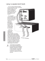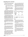
1
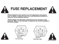
High Resolution Series Subwoofer HRS-8, HRS-1 0, and HRS-12 L...-------------~ User's Manual ~ ~ RISK OF ELECTRIC SHOCK DONOTOPEN ;j\ ~ CAUTION: TO REDUCE THE RISK OF ELECTRIC SHOCK DO NOT REMOVE COVER (OR BACK) NO USER-SERVICEABLE PARTS INSIDE REFER SERVICING TO QUALIFIED SERVICE PERSONNEL Important Safety Instructions 1. Read Instructions 2. Keep these Instructions 3. Heed all Warnings. 4. Follow all Instructions 5. Do not use this apparatus near water. 6. Clean only with dry cloth. 7. Do not install near any heat sources such as radiators, heat registers, stoves, or other apparatus (including amplifiers) that produce heat. 8. Unplug this apparatus during lightning storms or when unused for long periods of time. 9. Refer all servicing to qualified service personnel. Servicing is required when the apparatus has been damaged in any way, such as a power-supply cord or plug is damaged, liquid has been spilled or objects have fallen into the apparatus, the apparatus has been exposed to rain or moisture, does not operate normally, or has been dropped. 10. Ventilation -The apparatus should be situated so that its location or position does not interfere with its proper ventilation. For example, the apparatus should not be situated on a bed, sofa, rug, or similar surface that may block any ventilation openings; or placed in a built-in installation such as a bookcase, cabinet, or closed equipment rack that may impede the flow of air through ventilation openings. 11. Power Sources - The apparatus should be connected to a power supply only of the type described in these operation instructions or as marked on the apparatus. 12. Power Cord Protection - Power-supply cords should be routed so that they are not likely to.,be walked upon or pinched by items placed upon or against them, paying particular attention to cords at plugs, convenience The lightning flash with arrowhead symbol within an equilateral triangle is intended to alert the user to the presence of uninsulated "dangerous voltage" within the product's enclosure, that may be of sufficient magnitude to constitute a risk of electric shock to persons. The exclamation point within an equilateral triangle is intended to alert the user of the presence of important operating and maintenance (servicing) instructions in the literature accompanying the appliance. receptacles, and the point where they exit the apparatus. 13. Non-use Periods-The power cord of the apparatus should be unplugged from the outlet when unused for a long period of time. 14. Object and Liquid Entry - Care should be taken so that objects do not fall into and liquids are not spilled into the inside of the apparatus. 15. Servicing -The user should not attempt to service the apparatus beyond those means described in this operating manual. All other servicing should be referred to qualified service personnel. 16. To Prevent Electric Shock, do not use this polarized plug with an extension cord, receptacle or other outlet unless the blades can be fully inserted to prevent blade exposure. Pour preevenir les chocs electriques ne pas utiliser cette fiche polarisee avec un prolongateur, un prise de courant ou une autre sortie de courant, sauf si les lames peuvent etre inserees a fond sans laisser aucune pariie a decouvert. 17. Grounding or Polarization- Precautions should be taken so that the grounding or polarization means of the Component is not defeated. This apparatus does not exceed the Class A/Class 8 (whichever is applicable) limits for radio noise emissions from digital apparatus as set out in the radio interference regulations of the Canadian Department of Communications. ATTENTION - Le present appareil numerique n'emet pas de bruits radioelectriques depassant las limites applicables aux appareils numeriques de class A/de class 8 (selon le cas) prescrites dans le reglement sur le brouillage radioelectrique edicte par les ministere des communications du Canada: 11 • 2 - - " " * " " - - - - - - - - - - - - - - - - - - - - - - - - SUJ'!fire User's Manual 18. This equipment has been tested and found to comply with the limits for a Class B digital device, pursuant to Part15 of the FCC Rules. These limits are designed to provide reasonable protection against harmful interference in a residential installation. This equipment generates, uses and can radiate radio frequency energy and, if not installed and used in accordance with the instructions, may cause harmful interference to radio communications. However, there is no guarantee that interference will not occur in a particular installation. If this equipment does cause harmful interference to radio or television reception, which can be determined by turning the equipment off and on, the user is encouraged to try to correct the interference by one or more of the following measures: Reorient or relocate the receiving antenna. Increase the separation between the equipment and receiver. Connect the equipment into an outlet on a circuit different from that to which the receiver is connected. Consult the dealer or an experienced radio/TV technician for help. 19. Caution: Changes or modifications not expressly approved by Sunfire could void the user's authority to operate this equipment. WARNING:THIS SUBWOOFER IS CAPABLE OF PRODUCING VERY HIGH SOUND PRESSURE LEVELS. YOU MUST TAKE EVERY PRECAUTION TO PROTECT YOUR HEARING FROM PERMANENT DAMAGE. Contents Safety lnstructions ......................................... 2 Introduction ................................................... 4 Control Panel Features ................................. 6 Installation ..................................................... 8 System Configurations ................................ 11 Adjusting the Controls ................................. 15 Specifications .............................................. 16 Troubleshooting Guide ................................ 17 Limited Warranty ......................................... 19 Service Assistance ...................................... 19 To find out more about this and other Sunfire products, please visit our website: www.sunfire.com Surifjre User's Manual - - - - - - - - - - - - - - - - - - - - - - " * " - - 3 Introduction Thank you for purchasing a Sunfire High Resolution Series Subwoofer. We hope you enjoy it and the music it makes as much as we have enjoyed creating it for you. The big breakthrough features of the subwoofer are its uncanny 1,OOOW Tracking Downconverter amplifier, and its long throw, High Back-emf woofer. These powerful forces combine to produce as much bass as several 15 inch drivers mounted in a cabinet the size of a small refrigerator! And, the High Resolution Series' extended frequency response means that your subwoofer is the perfect match to virtually any loudspeaker. Unpacking Your Sunfire subwoofer should reach you in perfect condition. If you do notice any shipping damage, please contact your Sunfire Dealer immediately. Gently lift out the unit and remove all the packing material. It is important to save all the packing materials and the box in case your subwoofer ever needs to be moved or shipped for repair. Make sure that you keep your sales receipt. It is the only way to establish the duration of your Limited Warranty and it may come in useful for insurance purposes. Features • Patented high-pressure, High Backemf, extra-long-throw design • High efficiency Tracking Downconverter amplifier • Low distortion • Premium quality driver • Extremely compact size • Automatic signal-sensing turn-on and standby mode • Line-level inputs • Speaker-level binding post inputs • Line-le~el • Phase control • Crossover frequency control • Volume control • Soft clipping circuit allows graceful overload and prevents speaker damage due to clipping high-pass outputs Care To maintain the speaker cabinet's finish, first unplug the power cord and then use a soft cloth to clean the surfaces. If your Sunfire subwoofer needs servicing, please read the troubleshooting section on page 17. If a problem persists, contact your nearest authorized Sunfire Dealer. Please take a moment to fill out and mail the Sunfire Customer Response . card. Also read the serial number located on the control panel and record it here: Serial Number: Purchased from: Date: 4 - - r - - - - - - - - - - - - - - - - - - - - - - SUJ?fire User's Manual Overview The Sunfire HRS subwoofers are designed to give you the best possible low-frequency sound quality for your Home Theater and music playback experience. They incorporate a tremendously powerful built-in amplifier to produce tight, seismic, denture-rumbling bass that you can feel as well as hear. There are three models in the high resolution series: the HRS-8, HRS-1 0, and the HRS-12. (The number represents the driver diameter in inches.) The control panel, connections and operation are the same for each subwoofer model, and this manual covers all three models. If the input signal is driven even further, a 'soft clipping' circuit is enabled. This allows the driver to put more sound into the room to satiate the power hungry user, but without distortion or damage to the driver. This produces extremely high sound pressure levels (SPL) in your room without the driver banging against its mechanical stops. Sub/LFE In this manual, the term "Sub/LFE" is used to denote the subwoofer or Low Frequency Effects output, commonly found on Home Theater processors and receivers. Each subwoofer has controls for adjusting the crossover frequency, phase, and volume. They also have line-level and speaker-level inputs for easy incorporation into existing systems, or as part of a subwoofer/satellite speaker combination. The Driver To have lots of bass requires the movement of lots of air. To achieve this, the subwoofer's driver has been designed to travel back and forth approximately five times further than a normal driver. This gives lots of air movement and massive bass performance. The Tracking Downconverter Amplifier The large movement range of the driver generates greater air pressure inside the box than a conventional driver. In order to create this range of movement, we designed a drive amplifier that is much more powerful than an ordinary amplifier. A signal compressor circuit kicks in automatically if the input signal level reaches a level that would overload the driver. This maintains a ceiling on the output without clipping. Stuiflre User's Manual _ _ _ _ _ _ _ _ _ _ _ _ _ _ _ _ _ _ _ _ _____.,_ _ 5 Control Panel Features 5 1° 1-1®1_1_1_®------.. . -PHASE- VOLUME--- SPEAKER-LEVEL INPUTS - - I N P U T S ·CDCD· 0 ~e ® 9 10 6 7 8 e: NORMAL • • • ;:: __')(\. . ;. _ 1 -OOH- BYPASS 30HZ Sw?fire· HRS-8 8" Powered Subwoofer o· 110" MIN MAX DIM-ST~Y ~~· ~ ®[DJ:, ~ nsVT4AL210VACIOHZ ~ 1. Power Indicator This light is bright when the subwoofer is on, and dim when the subwoofer is in standby mode. 2. Power Switch Press the top of this rocker switch to turn on the subwoofer. The subwoofer has an automatic signal-detection circuit. After approximately fifteen minutes with no signal, the subwoofer will go into its quiet standby mode. The presence of an audio signal will turn it back on. Normally you can leave the switch on, and let the subwoofer turn on when a signal is present, or off when it's not. At night, or if you go out, or on vacation, you can press the bottom of the power switch to turn the subwoofer off. 230V TZ.&AL 250 VAC 50/BO HZ 250WATTS REPLACE FUSE W1TH SAME TYPE AND RATING \C) \C) 3 2 4 4. AC Line Fuse The subwoofer is supplied with a conservative slow-blow type fuse to protect the .electronics. If this fuse fails, replace it with the exact same type and current rating for your local AC voltage, as marked on the control panel near the fuse holder. Note: Always unplug the power cord from your AC outlet before removing the fuse. To replace or inspect the fuse, use a small flatended screwdriver to gently pry out the fuseholder and fuse. The AC voltage of the subwoofer is determined by the orientation of the fuseholder. Make sure the fuseholder is replaced in the correct orientation if the fuse is changed. 3. IEC Power Connector The subwoofer comes with a detachable linecord that attaches here. Make sure it is firmly pushed into place. Connect the other end to an AC outlet that is properly configured for the type of plug and has the correct voltage for your model. 6 - - * " " " " - - - - - - - - - - - - - - - - - - - - - SUJ?/ire User's Manual 5. Speaker-Level Inputs If you are using a receiver that only has speaker-level outputs, connect it using the speaker-level inputs (see the hookup diagram on page 14). They can accept bare wire, banana, or dual-banana connectors. If you experience excessive noise or· hum using the line-level inputs, try using the speaker-level inputs. This may lower the background noise level. 6. Line-Level Inputs These connect with RCA type cables from the line-level outputs of your receiver or preamp. Here are two examples: If your processor or receiver has a single subwoofer output, connect it to the subwoofer's left input jack (see page 11 ). There is no need to use the subwoofer's right input jack. If your processor does not have a subwoofer output, use "Y" adapters at the processor outputs (see page 12). In this way, you can send the processor's full-range output signals to your main amplifier and to the subwoofer at the same time. 7. High-Pass Outputs Signals from these output jacks are a direct copy of the signals going into the input jacks of the subwoofer, with the exception that the bass below 70 Hz has been removed by a fixed high-pass crossover circuit. This handy feature lets the subwoofer control all the bass in your system, and you can use an external amplifier and smaller satellite speakers to control the mids and highs. (See the hookup diagram on page 13.) We recommend using this high-pass function with small main/satellite speakers that are not designed to reproduce low frequencies. If you are used to the sound from smaller speakers, this option will really bring your system alive. If your main speakers are capable of operating full range, you will not need to use the high-pass function. 8. Crossover Frequency This controls the crossover frequency between 30 Hz and 100 Hz. If it is set to 30 Hz for example, the subwoofer will reproduce those frequencies below 30 Hz. Rotating the control clockwise will smoothly increase this frequency range up to 100 Hz. In the bypass position, the crossover control has no effect. You should set this to bypass if your processor has its own subwoofer crossover frequency control. If your processor does not have its own subwoofer crossover frequency control, rotate this control until the bass sounds natural. If the mid-bass sounds natural but you want more low bass, turn the crossover frequency down a little, then turn the volume up by about the same amount. This increases the low-bass output while leaving the mid-bass output the same. 9. Phase This controls the relative phase of the subwoofer with respect to your other speakers. Use this to help blend the subwoofer with the rest of your system. Adjust the control in small increments as you Iisten for the most bass at your listening position. As a final trim, readjust the crossover frequency and volume controls after the phase control has been set. 10.Volume This control lets you match the output level of the subwoofer to the level of your satellite/main speakers. The subwoofer output will increase as this control is rotated clockwise. When installing your system, turn this down first before turning on your subwoofer, to prevent any loud surprises. Sunjire User's Manual ----------------------~--7 Installation Observe the following general precautions and read the safety instructions on pages 2 and 3 before using your Subwoofer. Never open the cabinet or remove the metal control panel as this might result in an electrical shock to you or damage to the unit. Protect the subwoofer from prolonged exposure to direct sunlight and other direct sources of heat, such as heating vents and radiators. To prevent fire or shock, do not expose the unit to rain or moisture. If fluid or a foreign object should enter the unit, immediately turn off the power and contact your Dealer. Avoid excessive exposure to extreme cold or dust. Do not place heavy objects on top of the unit. Do not place the subwoofer with its control panel against the floor. Heat AC Power Considerations Ensure that the subwoofer is plugged into an outlet capable of supplying the correct voltage specified for your model. Unplug your subwoofer's power cord from the electrical outlet whenever you leave the subwoofer unused for a long period of time. II\ ~ Note: Never remove the ground pin from any power cords. This is very dangerous. Route the power supply cord away from areas where it is likely to be walked on, or pinched by items placed upon it or against it, especially near the AC wall socket, any multi power strips, or near where the IEC cord attaches to the component. Magnetic Fields We recommend that you place your subwoofer further than two feet away from your TV, VCR, tape deck or computer, so the speaker's magnet won't distort the colors of your TV picture or erase your video tapes, audio tapes or computer discs. Allow adequate ventilation around the metal control panel of the subwoofer. Let nothing come into contact with the panel and keep it at least two inches away from any walls. The metal control plate serves as the amplifier heat sink, and also removes internal heat to the outside and into the atmosphere. It can reach temperatures of 60 degrees C, which feels hot to the touch. 8 --~---------------------- Surifjre User's Manual Connections Please consider the following when setting up your new system: Choose reliable, high quality interconnect cables. They should be fully shielded and as short as possible for the job. The longest cable in your system will likely be to the subwoofer, so choose a good quality brand. Before making or changing any connections, ALWAYS make sure that the subwoofer and your other components are turned OFF. Turn down the volume control of both the subwoofer and your processor or receiver. Some cables can be a very tight fit and there is usually a preferred method of removing them. Some have to be removed with a twisting action. Be gentle, as twisting may cause damage to the jacks of the subwoofer or your other components. Tape Deck DVD Preamplifier Speaker-level connections The subwoofer's speaker-level inputs can accept speaker wires with banana, dual-banana, or bare wire. If you have banana-type connectors on your speaker wire, tighten the binding posts before inserting. Power strip Amplifier Make sure that the negative speaker wires never touch the positive wires. This will short out and possibly damage your amplifier or receiver. / AC outlets on the same circuit breaker Subwoofer • This diagram shows all the low power components sharing a power strip which is connected to the same outlet used by the main power amplifier. The subwoofer's two negative posts are joined internally (comman-grounded). Your amplifier or receiver must also be internally common-grounded or you cannot use this connection. Contact the manufacturer of your amplifier or receiver to make sure its outputs are common grounded. The subwoofer is connected to an outlet on the same circuit breaker, provided that the total system current draw does not exceed the breaker current rating. Whenever possible, keep the power cords away from the signal cables or speaker wires to prevent hum or interference. SUJ?fire User's Manual ----------------------~-- 9 Location Here is a neat trick to find the best subwoofer location for your room: 1. Start by placing it right on the seat of your favorite couch or easy chair. (This method is odd, but it is based on principles of acoustic physics). 2. If the subwoofer is part of a Home Theater system you can use the calibration test tone (pink noise) usually found in the processor/ receiver's setup menu; or you can simply plug the outputs from a CD player directly into the subwoofer's line-level inputs, remembering to turn down the volume level on the subwoofer first, and then playing some of your favorite music samples containing heavy bass. 3. Walk around the room listening. Stand in all the locations where you might place the subwoofer. Try crouching down, particularly in the corners. Find the place where the subwoofer's bass output sounds the loudest. 4. Turn off the subwoofer and disconnect it from the power and from your processor/receiver or CD player. Next, install the subwoofer in the location you have just determined is best and remake all your connections. Magnetic Fields Remember to keep the subwoofer at least two or three feet away from any TV screen, computer, VCR or magnetic tapes and discs. This will reduce the chance of the magnetic fields upsetting the TV screen or erasing your magnetic media. Using two Subwoofers If you wish to use two subwoofers, the sound output will double (an increase of 6 dB). Locate the subwoofers with one in each corner and experiment with the location and phase control to achieve the best bass response. Always drive each subwoofer through the left line-level input even though you are driving one subwoofer with a right channel drive and the other with a left channel drive. If your preamplifier has a single sub/LFE output, use a Y cable to split it into two outputs. Although low frequencies are non-directional, factors such as room reflections, standing waves, resonance and absorption will strongly affect your subwoofer's performance. Moving the subwoofer from one location to another can have a major effect on the bass response. 1Q- - " ' * - - - - - - - - - - - - - - - - - - - - - - - Surifjre User's Manual System Configurations The following pages show some typical connections that you might make in your installation. They show how the inputs and outputs of the Sunfire Subwoofer are connected to your preamplifier or receiver. Connections to a preamplifier's subwoofer output If your processor or receiver has a subwoofer output (Sub/LFE), it should be connected to the subwoofer's Left input as shown. This is the simplest and recommended connection. If you have a Home Theater processor or receiver, it probably has an independent subwoofer volume and crossover control. If so, you should set the subwoofer's volume control to 0 dB, set the crossover to Bypass, and use the processor's subwoofer level and frequency controls for adjustments. + - TO FRONT SPEAKERS SUJ?fire User's Manual - - - - - - - - - - - - - - - - - - - - - . . . . . - - 1 1 Connections using Y cables If your processor does not have a Sub/LFE output, you can use "Y" cables (or Y adaptors) to send its left and right main outputs to both the subwoofer and your amplifier. The subwoofer will play the low frequency range, and your front speakers will play the full range. Although bass is commonly distributed evenly between left and right channels (L +R bass), movie soundtracks often contain differential (L-R) bass. If this is not preserved, the bass in these scenes sounds anemic. The subwoofer utilizes differential gain on the left and right inputs to retain both the L +R and L-R information. Systems that do not have a dedicated Sub/LFE output should use both the left and the right inputs as shown, for the greatest bass impact. + - TO FRONT SPEAKERS 12 __. . . ___________ __________ _ Sunjire User's Manual Using the line-level high-pass outputs If you are using a receiver or processor which does not have a Sub/LFE output, you can send its left and right front output into the subwoofer's Line-Level inputs and then connect the subwoofer's High-Pass outputs to the inputs of your amplifier. The subwoofer will play the low frequencies, and your amplifier and front speakers will play the frequency range· above the subwoofer's fixed (70 Hz) high-pass crossover point. The signals coming out of the subwoofer's high-pass outputs are not affected by any of the controls. They are just a copy of the signals going into the subwoofer except that the low bass is filtered out. This uses the subwoofer's passive crossover network, set at 70 Hz, rather than the active network and other controls. This is an excellent method if your speakers are small satellites or minimonitors, and/or your power amplifier is + of limited power, such as a tube amp. TO FRONT SPEAKERS For the ultimate in computer sound systems, connect the left and right audio output from your computer sound card into the subwoofer inputs. Connect the sub's high-pass outputs to the inputs of your powered speakers. You may need some RCA-to-mini plug adaptors to make the connections. Adjust the sub's volume control to match low-powered speakers. See the note about magnetic fields on page 10. Sunjire User's Manual ----------------------~--13 Using the speaker-level inputs If you are using a receiver that does not have a subwoofer output or line-level outputs (pre-outs), you can connect its speaker outputs to the subwoofer's speaker-level inputs. The front speakers can still be connected to your receiver. The subwoofer's internal amplifier supplies the power to reproduce the low frequency range. It receives a sample of the signal going to your front speakers. (An insignificant fraction of your receiver's power is transferred to the subwoofer). There is no need to use the speaker-level inputs if you are using a separate preamplifier/ processor and a power amplifier. Such systems are best connected using the line-level inputs as shown in the previous diagrams. However, if you are using the line-level inputs and there is a excessive amount of noise or hum present, using the speaker-level inputs may yield a lower background noise level. + TO FRONT SPEAKERS The subwoofer's two negative posts are joined internally (common-grounded). Your receiver/power amplifer must also be internally common-grounded or you cannot use this connection. Contact the manufacturer of your receiver to make sure its outputs are common grounded. 14 __..,._________ _______ _______ _ SUJ?fire User's Manual Adjusting the controls There are two main methods for adjusting the volume, crossover frequency and phase controls to match a system: Preferred method: By listening and making the adjustments to suit your taste. Laboratory method: By measuring the output with a microphone and adjusting for a flat frequency response. Excellent results can be obtained if you make the adjustments based on simply listening. This is our preferred method as it allows the system to be voiced based on what sounds the best, whereas laboratory-flat frequency response can often be clinical and less than exciting. The following procedure is for those who prefer a more methodical and scientific approach. This excerpt is from "The Audio Critic," issue 24, page 31, written by contributing editor David Rich, and is reprinted here with their kind permission. You will need a test CD with low-frequency warble tones, and a sound pressure-level meter. The Radio Shack® SPL meter will do fine, as will the Stereophife® test CD. "Step 1. Disconnect the subwoofer and run the main speaker with a tone in its passband (80-1 00 Hz). Measure the level. Step 2. Disconnect the main speaker and reconnect the subwoofer. Set the subwoofer to its highest crossover frequency. Set the volume control of the subwoofer to give the same sound pressure level with the .same tone you used in Step 1. Step 3. With both the subwoofer and the main speaker connected, measure the level of the tones at the available frequencies. Because the crossover is set too high, you will have a peaked response. Adjust the crossover control to get the smoothest response. Step 4. Use the phase control to make the response even smoother. It has its biggest effect at the crossover frequency. You can iterate between the crossover and the phase controls. Keep your hands off the volume control! It was set correctly in step 2. Step 5. Listen to the subwoofer. Resist all temptations to turn up the volume control. Play something with really deep bass to confirm that your subwoofer is working." Record your favorite settings here: CROSSOVER FREQUENCY NORMAL 65HZ PHASE VOLUME 90° 0 dB ffiOOHffi ffi 30 HZ BYPASS 0° 180° MIN MAX Note: Some Home Theater processors and receivers have an internal crossover adjustment which allows you to vary how much of the bass frequency range is sent to the su bwoofer. In these systems, it is recommended that you set your subwoofer's own crossover control to maximum frequency, or "Bypass." You can then make any crossover frequency adjustments using your Home Theater processor or receiver controls. If the subwoofer's internal crossover is set to a frequency lower than the one on your Home Theater processor or receiver, there would be a hole in the mid-bass, and bass information would be missing. SUJ?fire User's Manual - - - - - - - - - - - - - - - - - - - - - - * - - - 1 5 Specifications Amplifier Output 1 ,000 watts rms High Cut Filter 30 Hz - 100 Hz adjustable. The crossover can be bypassed by rotating the crossover frequency control fully clockwise. Frequency Response HRS-8 HRS-10 HRS-12 22Hz-100Hz 20Hz-100Hz 18Hz-100Hz Power Line Voltage 115 VAC 50/60 Hz version 230 VAC 50/60 Hz version Dimensions HRS-8 HRS-10 HRS-12 10.0" (254 mm) cubed 11.5" (292.1 mm) cubed 13.5" (343 mm) cubed Weight HRS-8 HRS-10 HRS-12 Input sensitivity for full output: 240 mVrms from left input with volume control at 0 dB, 90 mVrms with volume control fully clockwise. 0.48 Vrms from right input with volume control at 0 dB, 180 mVrms with volume control fully clockwise. Input impedance: 30 KQ for Line-Level inputs 5.6 KQ for speaker or Hi-Level inputs Drivers: HRS-8 HRS-10 HRS-12 8" (203.2 mm) 10" (254 mm) 12" (304.8 mm) Extra-large magnet and long throw mechanical design yields very high back-emf. The result is extraordinarily high operating efficiency- that is, more acoustic output for each watt of input. Internal system gain: 28 lbs (12. 7 kg) 34 lbs (15.4 kg) 38 llbs (17.2 kg) Finish High-gloss black cabinet, black anodized amp plate, black fabric grill. 42 dB from left input jack to subwoofer with volume control at OdB. 54 dB with control fully clockwise. 36 dB from right input jack to subwoofer with volume control at OdB, 48 dB with control fully clockwise. Line power consumption: 600 watts average, at maximum continu- . ous output, 18 to 100 Hz. 2,000 watts peak, time limited basis. Output levels: Peak SPL HRS-8 HRS-10 HRS-12 (including room gain): 102dB 105 dB 108 dB © 2009 Sunfire, a division of Elan Home Systems, LLC. All rights reserved. Sunfire reserves the right to improve its products at any time. Therefore, specifications are subject to change without notice. Manual 913-140-00 Rev D 16 -~E-------------------- SU1?/ire User's Manual Troubleshooting This subwoofer has been designed and built to provide years of trouble-free performance. Most problems that occur can usually be solved by checking your setup, or by making sure that the components connected to the amplifier are on and fully operational. The following information will help you deal with common problems you may experience during normal use. If a problem persists, please contact your Dealer for assistance. Not enough bass • Check that your processor's outputs are connected to the subwoofer's line-level inputs and not to the line-level high pass outputs. If they are connected to the outputs by mistake, the bass will be weak but the subwoofer will still function. • If your processor has a single subwoofer/ LFE output jack, make sure it connects to the subwoofer's Left input. If the bass is still not enough after checking all the remaining points, use a Y cable to connect the processor's single subwoofer/LFE output to the subwoofer's left and right inputs. • Try moving the subwoofer to a different location. See Location on page 10. Placing it in a corner will maximize the bass output and give the smoothest possible response. • Home Theater processors usually have a way of adjusting the level of the subwoofer/LFE output, either using a remote control or with a small volume knob on the back panel. Make sure that this is adjusted correctly. Not enough bass in a 5.1 system • 5.1 Home Theater processors usually have a bass management system which allows the bass to be redirected among your speakers. For example, the bass normally present in the front speakers can be redirected to play in the subwoofer, or the subwoofer can play the bass from all the speakers, in addition to its dedicated LFE (low frequency effects) channel. Make sure that all of the bass management options are correctly set. The processor may have a way of turning the subwoofer output off entirely, so check that it is always on. • Check that the processor calibration procedure is correctly adjusted. Usually, the preamp will send a test tone through all the speakers in your system, allowing you to adjust (trim) the volume of each channel until they are all playing at the same level. • If the bass is weak only when playing 5.1 surround sources, check that your processor is correctly set to decode the 5.1 surround modes, such as Dolby Digital or DTS. • Some DVD discs have a menu which allows you to select which soundtrack to play. Check that the correct 5.1 surround audio soundtrack is selected, otherwise it may just play stereo into your preamp and you won't get the true LFE signal into the subwoofer. • Check that your processor or receiver's sub output is turned on. Some systems only have a sub output signal when the front speakers are set to "small." • If the processor's Sub/LFE output has an adjustable crossover frequency, make sure that the subwoofer's own crossover point is set to Bypass or part of the bass range may be missing. SUJ?/ire User's Manual - - - - - - - - - - - - - - - - - - - - - - - + - - 1 7 Hum Adding any component such as a subwoofer to an existing system will often give rise to a hum which wasn't there before. Your first thought may be that the subwoofer has a problem, but this is more than likely caused by a "ground-loop" in your system. Follow these steps to isolate the main cause of the ground-loop hum (there may even be more than one cause). • Try to have all of your equipment on the same electrical outlet or circuit, provided that the total current draw does not exceed the current safety rating of the outlet or circuit. • If your subwoofer is a fair distance away from your other equipment, you may use a 15 amp extension cord as long as it has a ground connection. • Turn off all components in your system, including the subwoofer, amplifiers and the processor, before disconnecting or connecting cables. • First remove every connection from the subwoofer to the rest of your system. Plug the subwoofer power cord back in and check for the hum. If it is still there, try plugging it into a different outlet in case it is picking up interference on the AC line. • If you have followed the above guidelines for the power connections and a hum is still present, then there is one very common problem to consider: a "ground-loop" introduced by connecting a cable TV line to a VCR or TV, which is then connected to the preamp. This can be addressed as follows: • Disconnect all cables which come from outside the room, such as cable TV, satellite TV, or roof top antennas. Make sure that they are disconnected where they first enter the room, so they are making no connection to your processor, TV, or any other component. If the hum is caused by the cable TV line, then you will need a "ground-loop isolator." This is an inexpensive device fitted in line with the coaxial cable feed. • If the hum persists, disconnect all the source components one at a time from the back of the processor until you identify the problem. • If you are using the subwoofer's line-level inputs and there is a excessive amount of noise or hum present, try using the speaker-level inputs as they may yield a lower background noise level. • Ground-loop isolators are available for audio lines and video. Once you have identified which components are causing a problem, you can fit the isolators between the component and the preamp. No auto turn off • The subwoofer should turn itself off after approximately fifteen minutes with no audio signal present. If not, check there is no background hum. The subwoofer may sense hum as a small signal and stay on. See the above hints to eliminate the hum. No auto turn on • The subwoofer's volume control may be turned down, or no signal is received from your processor. • Check the input connections. • Check on surround systems to be certain that a bass signal is being sent to the subwoofer. DECLARATION OF CONFORMITY, ACCORDING TO EN 45014 Sunfire Manufacturer's name: Manufacturer's address: 1300 E. New Circle Rd., Suite 150, Lexington, KY USA Declares that the products listed on this declaration: Product name(s): Amplified subwoofer speaker Product Model Number(s): HRS-8, HRS-10, HRS-12 Conform to the following product specifications: IEC 60065:2001 JEN 60065:2002 Safety: EN 55013:2001 +AI:2003+A2: 2006 EMC: EN 55020:2002 + Al:2003 + A2:2005 EN 61000-3-2:2000 + A2:2005 EN 61000-3-3:1995 + Al:2001 +A2:2005 The product hereinwith complies with the provisions of the following European Directives and carries the CE mark accordingly: Low voltage directive 73/231 EEC, as amended Electromagnetic Compatibility Directive 89J3361 EEC, as amended Supplementary information: The product was tested in a typical configuration Signed: Date 05/18/09 Mark Weisenberg General Manager 18 - - - + - - - - - - - - - - - - - - - - - - - - - - - - SUJ?fire User's Manual Sunfire Limited Warranty Sunfire, a division of Elan Home Systems, LLC, is proud of its products which have been built with care using advanced technology and premium component parts. Your unit has been crafted to perform properly for many years. Sunfire offers the following Warranty to you, the owner of a new Sunfire product: Sunfire warrants the HRS subwoofer to be free from defects in materials and workmanship for the period of ONE year from the date of purchase. If within the applicable warranty period above purchaser discovers such item was not as warranted above and promptly notifies Sunfire in writing, Sunfire shall repair or replace the items at the company's option. This warranty shall not apply: (a) to equipment not manufactured by Sunfire. THE FOREGOING WARRANTIES ARE EXCLUSIVE AND IN LIEU OF ALL OTHER EXPRESSED AND IMPLIED WARRANTIES EXCEPT WARRANTIES OF TITLE, INCLUDING BUT NOT LIMITED TO IMPLIED WARRANTIES OF MERCHANTABILITY AND FITNESS FOR A PARTICULAR PURPOSE. ATTENTION: TO OUR VALUED CONSUMERS To insure that consumers obtain quality pre-sale and after-sale support and service, Sunfire products are sold exclusively through authorized dealers. Sunfire products are not sold online. The warranties on Sunfire products are NOT VALID if the products have been purchased from an unauthorized dealer or an online E-tailer. To determine if your Sunfire re-seller is authorized, please call Sunfire at (859) 514-8290. (b) to equipment which shall have been installed by other than an authorized Sunfire installer. Service Assistance (c) to installed equipment which is not installed to Sunfire's specifications. We suggest that you read the Limited Warranty completely to fully understand your Warranty/Service coverage. (d) to equipment which shall have been repaired or altered by others than Sunfire. If your Sunfire product ever requires service, write to us or call: (e) to equipment which shall have been subjected to negligence, accident, or damSunfire, age by circumstances beyond Sunfire's 1300 E New Circle Road, Suite 150 control, including, but not limited to, Lexington, KY 40505 lightning, flood, electrical surge, tornado, Phone 859-514-8290 earthquake, or any other catastrophic Fax: 859-269-7972 events beyond Sunfire's control, or to You will be directed to an authorized Sunfire improper operation, maintenance or Service Station or receive instructions to storage, or to other than normal use of ship the unit to the factory. Please save the service. original shipping carton and packing materiWith respect to equipment sold by, but not als in case shipping is required. Please do manufactured by Sunfire, the warranty not ship Parcel Post. obligations of Sunfire shall in all respects conform and be limited to the warranty actu- NOTE: Before sending in your unit for repair, ) ally extended to Sunfire by its supplier. The you must call Sunfire for return authorization. foregoing warranties do not cover reimbursement for labor, transportation, removal, Include a complete description of the probinstallation, or other expenses which may lem, indicating how you have it connected, be incurred in connection with repair or the associated equipment in your system replacement. and a copy of your purchase receipt. Initial Except as may be expressly provided and shipping costs are not paid by Sunfire; authorized in writing by Sunfire, Sunfire shall return ground shipping costs will be prepaid not be subject to any other obligations or if repairs were covered by the scope of this liabilities whatsoever with respect to equipWarranty. ment manufactured by Sunfire or services rendered by Sunfire. I SUJ?!fre User's Manual ----------------------~--19 --IRS~ High Resolution Series Subwoofer HRS-8, HRS-1 0, and HRS-12 Sunfire 1300 E New Circle Road Suite 150, Lexington, KY 40505 Phone: 859-514-8290 Fax: 859-269-7972 www.sunfire.com Manual part number 913-140-00 Rev 0 FUSE REPLACEMENT Always unplug the power cord from your AC outlet before removing the fuse. To replace or inspect the fuse, use a small flatended screwdriver to gently pry out the fuseholder and fuse. The AC voltage of the subwoofer is determined by the orientation of the fuseholder. Make sure the fuseholder is replaced in the corr~ct orientation if the fuse is changed. ~~~ .... 220-240 USE ONLY WITH A 250V FUSE EMPLOYER UNIQUEMENT AVEC UN FUSIBLE DE 250V Set for 110-120 VAC ~~~ .&on-ott AOSZ 30 3191Sn;j Nn )3A't/ lN3W3nOINn H3AOldW3 3Sn;j AOSZ 't/ HliMAlNO 3Sn Set for 220-240 VAC •' P/N 913-161-00 REV: A · =--=XT CUSTOMER RESPONSE CARD Thank you for purchasing one of our products. Please complete this form to register, or visit us online at sunfire.com. ~heredidyoufirstlearnaboutourproducts?~~~~~~~~~~~~~~~~ ~hat factors convinced you to purchase this p r o d u c t ? - - - - - - - - - - - - ~hat other components would you like to see us produce? ~~~~~~~~~~- ~hen did you purchase your product? Purchase Price?~~~~~- ~here did you purchase your product?------------------~ ~as this product installed by a professional installer? D Yes D No Model: ~~~~~~-~~~~- Serial Number: Comments: - - - - - - - - - - - - - - - - - - - - - - - - - - - - - Name: Age: E-mail: _ _ _ _ _ _ _ _ _ _ _ __ Address: - - - - - - - - - - - - - - - - - - - - - - - - - - - - - - - - - - - - - - D Please contact me via e-mail regarding Sunfire product information and promotions. From: AFFIX STAMP HERE Sunfire 1300 E New Circle Road Suite 150, Lexington, KY 40505