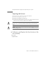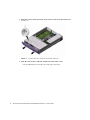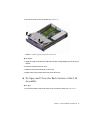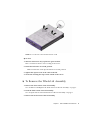
1
Sun Fire V210 and V240 Servers
Parts Replacement Manual
Sun Microsystems, Inc.
4150 Network Circle
Santa Clara, CA 95054 U.S.A.
650-960-1300
Part No. 817-0743-10
January 2003, Revision A
Send comments about this document to: [email protected]
Copyright 2002 Sun Microsystems, Inc., 4150 Network Circle, Santa Clara, CA 95054 U.S.A. All rights reserved.
This product or document is distributed under licenses restricting its use, copying, distribution, and decompilation. No part of this product or
document may be reproduced in any form by any means without prior written authorization of Sun and its licensors, if any. Third-party
software, including font technology, is copyrighted and licensed from Sun suppliers.
Parts of the product may be derived from Berkeley BSD systems, licensed from the University of California. UNIX is a registered trademark in
the U.S. and other countries, exclusively licensed through X/Open Company, Ltd.
Sun, Sun Microsystems, the Sun logo, AnswerBook2, docs.sun.com, and Solaris are trademarks, registered trademarks, or service marks of Sun
Microsystems, Inc. in the U.S. and other countries. All SPARC trademarks are used under license and are trademarks or registered trademarks
of SPARC International, Inc. in the U.S. and other countries. Products bearing SPARC trademarks are based upon an architecture developed by
Sun Microsystems, Inc. The Energy Star logo is a registered trademark of EPA.
The OPEN LOOK and Sun™ Graphical User Interface was developed by Sun Microsystems, Inc. for its users and licensees. Sun acknowledges
the pioneering efforts of Xerox in researching and developing the concept of visual or graphical user interfaces for the computer industry. Sun
holds a non-exclusive license from Xerox to the Xerox Graphical User Interface, which license also covers Sun’s licensees who implement OPEN
LOOK GUIs and otherwise comply with Sun’s written license agreements.
Federal Acquisitions: Commercial Software—Government Users Subject to Standard License Terms and Conditions.
DOCUMENTATION IS PROVIDED “AS IS” AND ALL EXPRESS OR IMPLIED CONDITIONS, REPRESENTATIONS AND WARRANTIES,
INCLUDING ANY IMPLIED WARRANTY OF MERCHANTABILITY, FITNESS FOR A PARTICULAR PURPOSE OR NON-INFRINGEMENT,
ARE DISCLAIMED, EXCEPT TO THE EXTENT THAT SUCH DISCLAIMERS ARE HELD TO BE LEGALLY INVALID.
Copyright 2002 Sun Microsystems, Inc., 4150 Network Circle, Santa Clara, CA 95054 Etats-Unis. Tous droits réservés.
Ce produit ou document est distribué avec des licences qui en restreignent l’utilisation, la copie, la distribution, et la décompilation. Aucune
partie de ce produit ou document ne peut être reproduite sous aucune forme, par quelque moyen que ce soit, sans l’autorisation préalable et
écrite de Sun et de ses bailleurs de licence, s’il y en a. Le logiciel détenu par des tiers, et qui comprend la technologie relative aux polices de
caractères, est protégé par un copyright et licencié par des fournisseurs de Sun.
Des parties de ce produit pourront être dérivées des systèmes Berkeley BSD licenciés par l’Université de Californie. UNIX est une marque
déposée aux Etats-Unis et dans d’autres pays et licenciée exclusivement par X/Open Company, Ltd.
Sun, Sun Microsystems, le logo Sun, AnswerBook2, docs.sun.com, et Solaris sont des marques de fabrique ou des marques déposées, ou
marques de service, de Sun Microsystems, Inc. aux Etats-Unis et dans d’autres pays. Toutes les marques SPARC sont utilisées sous licence et
sont des marques de fabrique ou des marques déposées de SPARC International, Inc. aux Etats-Unis et dans d’autres pays. Les produits portant
les marques SPARC sont basés sur une architecture développée par Sun Microsystems, Inc.
L’interface d’utilisation graphique OPEN LOOK et Sun™ a été développée par Sun Microsystems, Inc. pour ses utilisateurs et licenciés. Sun
reconnaît les efforts de pionniers de Xerox pour la recherche et le développement du concept des interfaces d’utilisation visuelle ou graphique
pour l’industrie de l’informatique. Sun détient une licence non exclusive de Xerox sur l’interface d’utilisation graphique Xerox, cette licence
couvrant également les licenciés de Sun qui mettent en place l’interface d’utilisation graphique OPEN LOOK et qui en outre se conforment aux
licences écrites de Sun.
Achats fédéraux : logiciel commercial - Les utilisateurs gouvernementaux doivent respecter les conditions du contrat de licence standard.
LA DOCUMENTATION EST FOURNIE “EN L’ETAT” ET TOUTES AUTRES CONDITIONS, DECLARATIONS ET GARANTIES EXPRESSES
OU TACITES SONT FORMELLEMENT EXCLUES, DANS LA MESURE AUTORISEE PAR LA LOI APPLICABLE, Y COMPRIS NOTAMMENT
TOUTE GARANTIE IMPLICITE RELATIVE A LA QUALITE MARCHANDE, A L’APTITUDE A UNE UTILISATION PARTICULIERE OU A
L’ABSENCE DE CONTREFAÇON.
Please
Recycle
Contents
Contents
1.
iii
Figures
vii
Preface
ix
Parts Installation and Removal
Replaceable Components
3
Controlling Server Power
3
1
▼
To Power On the Server
3
▼
To Power Off the Server
4
Avoiding Electrostatic Discharge
5
▼
To Avoid Electrostatic Discharge While Working on the Back of the
Server 5
▼
To Avoid Electrostatic Discharge While Working on the Front of the
Server 6
Opening the Server
7
▼
To Remove and Replace the Front Section of the Lid Assembly
▼
To Open and Close the Back Section of the Lid Assembly
▼
To Remove the Whole Lid Assembly
Location of Components
Front Bezel Assembly
7
9
11
12
15
Contents
iii
▼
To Replace the Bezel Assembly
Hard Disk Drives
▼
15
To Remove and Replace a Hard Disk Drive
System Configuration Card Reader
▼
15
15
17
To Remove and Replace the System Configuration Card Reader
Power Supply Unit
19
▼
To Replace the PSU in a Sun Fire V210 Server
▼
To Replace a PSU in a Sun Fire V240 Server
20
20
Power Distribution Board (Sun Fire V240 Server Only)
▼
▼
24
To Add or Remove Memory
Cooling Fans
22
24
Memory Configuration Rules
▼
22
To Remove and Replace the Power Distribution Board
Adding Memory
17
25
26
To Remove and Replace a Fan
CPU Heatsink Assembly
26
27
CPU and System Board Assembly
29
▼
To Remove the System Board
▼
To Install a System Board
29
32
Upper and Lower Interface Board Assemblies
32
▼
To Remove and Replace an Upper Interface Board Assembly (Sun Fire
V240 Server Only) 32
▼
To Remove and Replace a Lower Interface Board Assembly
PCI Cards
▼
36
To Add or Replace a PCI Card
37
PCI Riser Card (Sun Fire V240 Server Only)
▼
38
To Remove and Replace the PCI Riser Card Assembly
Hardware Cryptographic Module
▼
34
38
40
To Remove and Replace the Hardware Cryptographic Module
40
Contents
iv
Battery
▼
41
To Replace the RTC Battery
Keyswitch Assembly
Index
41
42
45
Contents
v
vi
Sun Fire V210 and V240 Servers Parts Replacement Manual • January 2003
Figures
FIGURE 1-1
Grounding Point in the Back of the Servers (Sun Fire V240 shown) 6
FIGURE 1-2
Location of Screws on the Front Section of the Lid
FIGURE 1-3
Removing the Front Section of the Lid 9
FIGURE 1-4
Location of Captive Screw and Side Catches on Back Section of Lid
FIGURE 1-5
Location of Catch on Back Section of Lid 11
FIGURE 1-6
Removing the U-Channel 12
FIGURE 1-7
Location Of Major Components in a Sun Fire V210 Server
FIGURE 1-8
Exploded View of Components in a Sun Fire V240 Server 14
FIGURE 1-9
Removing a Hard Disk Drive
FIGURE 1-10
Location of Plugs on the System Configuration Card Reader 18
FIGURE 1-11
Removing the System Configuration Card Reader 19
FIGURE 1-12
Power Supply Unit Lever on a Sun Fire V240 Server
FIGURE 1-13
Removing a PSU on a Sun Fire V240 Server 21
FIGURE 1-14
Location of PDB Connectors on the System Board
FIGURE 1-15
Removing the Power Distribution Board (Sun Fire V240 Only) 23
FIGURE 1-16
Inserting Memory
FIGURE 1-17
Disconnecting a Fan Power Cable (Sun Fire V240 server shown) 26
FIGURE 1-18
Removing Fans (Sun Fire V240 server shown)
FIGURE 1-19
Removing a Processor Fan and Heat Sink Assembly 28
FIGURE 1-20
Accessing the System Board to Remove It 30
8
10
13
16
21
23
25
27
Figures
vii
viii
FIGURE 1-21
Removing the System Board from the Chassis 31
FIGURE 1-22
Removing Lid Assembly and Hard Disk Drives to Access Interface Boards 33
FIGURE 1-23
Removing the Interface Boards
FIGURE 1-24
Lower Interface Board Standoff and Screw Locations
FIGURE 1-25
Location of PCI Lockdown Screw
FIGURE 1-26
Removing a PCI Card on a Sun Fire V240 Server
FIGURE 1-27
Location of PCI Riser Card Screws 39
FIGURE 1-28
Removing the PCI Riser Card Assembly
FIGURE 1-29
Removing the Hardware Cryptographic Module 41
FIGURE 1-30
Disconnecting the Keyswitch Wiring Harness 43
FIGURE 1-31
Removing the Keyswitch Locknut 43
FIGURE 1-32
Removing the Keyswitch Assembly
34
36
37
38
40
44
Sun Fire V210 and V240 Servers Parts Replacement Manual • January 2003
Preface
The Sun Fire V210 and V240 Servers Parts Replacement Manual is for the use of
qualified service personnel only. It provides detailed instructions about service
procedures for the Sun Fire V210 and V240 servers.
Before You Read This Book
This book does not cover server installation and rackmounting. For detailed
information on those topics, refer to the Sun Fire V210 and V240 Servers Installation
Guide.
Before following any of the procedures described in this book, ensure you have read
the Sun Fire V210 and V240 Servers Compliance and Safety Manual.
Using UNIX Commands
This document does not contain information on basic UNIX® commands and
procedures such as shutting down the system, booting the system, and configuring
devices.
See one or more of the following for this information:
■
■
Solaris Handbook for Sun Peripherals
Other software documentation that you received with your system
ix
Typographic Conventions
Typeface
Meaning
Examples
AaBbCc123
The names of commands, files,
and directories; on-screen
computer output
Edit your.login file.
Use ls -a to list all files.
% You have mail.
AaBbCc123
What you type, when contrasted
with on-screen computer output
% su
Password:
AaBbCc123
Book titles, new words or terms,
words to be emphasized.
Replace command-line variables
with real names or values.
Read Chapter 6 in the User’s Guide.
These are called class options.
You must be superuser to do this.
To delete a file, type rm filename.
Shell Prompts
x
Shell
Prompt
C shell
machine-name%
C shell superuser
machine-name#
Bourne shell and Korn shell
$
Bourne shell and Korn shell superuser
#
ALOM shell
sc>
OpenBoot PROM shell
ok
Sun Fire V210 and V240 Servers Parts Replacement Manual • January 2003
Related Documentation
Application
Title
Part Number
Latest information
Sun Fire V210 and V240 Servers
Product Notes
816-4828-xx
Compliance and Safety
Sun Fire V210 and V240 Servers
Compliance and Safety Manual
816-4827-xx
Unpacking
Sun Fire V210 and V240 Servers
Quick Start Guide
816-4824-xx
Installation
Sun Fire V210 and V240 Servers
Installation Guide
816-4825-xx
Administration
Sun Fire V210 and V240 Servers
Administration Guide
816-4826-xx
Lights-Out Management
Advanced Lights-Out Manager Online
Help
817-0076-xx
Read the Sun Fire V210 and V240 Servers Compliance and Safety Guide before
performing any of the procedures documented in this manual.
Accessing Sun Documentation Online
You can view, print, or purchase a broad selection of Sun documentation, including
localized versions, at:
http://www.sun.com/documentation
Sun Welcomes Your Comments
Sun is interested in improving its documentation and welcomes your comments and
suggestions. You can email your comments to Sun at:
[email protected]
Preface
xi
Please include the part number (817-0743-10) of your document in the subject line of
your email.
xii
Sun Fire V210 and V240 Servers Parts Replacement Manual • January 2003
CHAPTER
1
Parts Installation and Removal
This chapter contains procedures for replacing the server’s internal hardware
components.
Caution – The procedures in this section are for the attention of qualified service
engineers only.
Caution – Read “Avoiding Electrostatic Discharge” on page 5, and wear a properly
grounded antistatic strap, before you carry out any of the procedures in this book.
The chapter contains the following sections:
■
“Replaceable Components” on page 3
■
“Controlling Server Power” on page 3
■
“Avoiding Electrostatic Discharge” on page 5
■
“Opening the Server” on page 7
■
“Location of Components” on page 12
■
“Front Bezel Assembly” on page 15
■
“Hard Disk Drives” on page 15
■
“System Configuration Card Reader” on page 17
■
“Power Supply Unit” on page 19
■
“Power Distribution Board (Sun Fire V240 Server Only)” on page 22
■
“Adding Memory” on page 24
■
“Cooling Fans” on page 26
■
“CPU Heatsink Assembly” on page 27
■
“CPU and System Board Assembly” on page 29
■
“Upper and Lower Interface Board Assemblies” on page 32
1
2
■
“PCI Cards” on page 36
■
“PCI Riser Card (Sun Fire V240 Server Only)” on page 38
■
“Hardware Cryptographic Module” on page 40
■
“Battery” on page 41
■
“Keyswitch Assembly” on page 42
Sun Fire V210 and V240 Servers Parts Replacement Manual • January 2003
Replaceable Components
Replaceable components in the front section of the server are:
■
■
■
■
■
■
Bezel assembly
Hard disk drive
System configuration card reader
Lower interface board
Upper interface board (Sun Fire V240 server only)
Keyswitch assembly (Sun Fire V240 server only)
The remaining replaceable components are in the back section of the server.
Caution – Printed circuit boards and hard disk drives contain electronic
components that are extremely sensitive to static electricity. Ordinary amounts of
static from your clothes or the work environment can destroy components.
Do not touch the components or any metal parts without taking proper antistatic
precautions.
Before you carry out the procedures covered in this book, the server must be
powered down. To do this you must remove the power cable. Follow the
instructions in “To Power Off the Server” on page 4.
Controlling Server Power
The On/Standby button cannot power off the server. It toggles the server between
on and standby.
▼
To Power On the Server
Caution – Never move the system when the system power is on. Movement can
cause catastrophic disk drive failure. Always power off the system before moving it.
1. Connect the server to an AC power source.
Once connected, the server automatically goes into Standby power mode.
Chapter 1
Parts Installation and Removal
3
2. Turn on power to any peripherals and external storage devices you have connected
to the server.
Read the documentation supplied with the device for specific instructions.
3. Open the bezel.
4. Sun Fire V240 server only: insert the system key into the keyswitch and set it to
the Normal or Diagnostics position.
5. Press the On/Standby switch.
6. Sun Fire V240 server only:
a. Turn the key switch to the Locked position.
This prevents anyone from accidentally powering off the system.
b. Remove the system key from the keyswitch and secure it in the clip inside
bezel.
7. Close the bezel.
▼
To Power Off the Server
1. Notify users that the system will be powered down.
2. Back up system files and data.
3. Sun Fire V240 server only: ensure that the keyswitch is in the Normal or
Diagnostics position.
4. Press and release the On/Standby switch behind the bezel.
The system begins an orderly software system shutdown.
Note – Pressing and releasing the On/Standby switch initiates an orderly software
shutdown. Pressing and holding the switch for four seconds causes an immediate
hardware shutdown. Whenever possible, initiate an orderly shutdown. Forcing an
immediate hardware shutdown can corrupt the disk drive and cause loss of data.
5. Wait for the front panel green LED to go out.
6. Sun Fire V240 server only: remove the system key from the keyswitch and secure
it in the clip inside the bezel.
7. Disconnect the power cable.
This is the only way to remove power from the server. Electrical power is present
when the server is in Standby mode.
4
Sun Fire V210 and V240 Servers Parts Replacement Manual • January 2003
Caution – As long as the power cord is connected, potentially hazardous energy is
present inside the server.
Avoiding Electrostatic Discharge
Whenever you work with the server’s internal components, follow this procedure to
prevent damage caused by static electricity.
You need the following items:
■
■
▼
Antistatic wrist or foot strap
Antistatic mat
To Avoid Electrostatic Discharge While Working
on the Back of the Server
1. Power off the system.
See “Controlling Server Power” on page 3.
2. Open the back section of the lid.
See “Opening the Server” on page 7.
Chapter 1
Parts Installation and Removal
5
3. Attach one end of the antistatic strap to the grounding stud located on the
partition inside the server, and the other end to your wrist.
FIGURE 1-1
▼
Grounding Point in the Back of the Servers (Sun Fire V240 shown)
To Avoid Electrostatic Discharge While Working
on the Front of the Server
1. Power off the system.
See “Controlling Server Power” on page 3.
2. Either:
● Attach one end of the antistatic strap to a grounding point on the rack and the
other to your wrist, or
a. Remove the server from the rack.
b. Place the server on an antistatic mat or other suitable antistatic surface.
Suitable antistatic surfaces include:
6
■
Sun electrostatic discharge (ESD) mat, Sun part number 250-1088 (available
through your Sun sales representatives)
■
The bag or shipping container used to package Sun replacement parts
Sun Fire V210 and V240 Servers Parts Replacement Manual • January 2003
■
Disposable ESD mat, shipped with replacement parts or options
Opening the Server
The lid of the server is split into two sections, front and back.
■
The back section hinges to provide access.
■
The front section detaches to provide access.
■
The whole lid assembly detaches to provide access to both front and back sections
of the server. This is necessary to replace some components.
Caution – Disconnect the power cord before carrying out this procedure. As long as
the power cord is connected, potentially hazardous energy is present inside the
server.
Caution – After servicing, replace and fasten the lid before plugging in the power
cords or turning power on.
▼
To Remove and Replace the Front Section of the
Lid Assembly
● To remove:
1. Open the bezel.
Chapter 1
Parts Installation and Removal
7
2. Undo the screws which fasten the front section of the lid to the chassis (see
FIGURE 1-2).
FIGURE 1-2
Location of Screws on the Front Section of the Lid
3. Slide the front section of the lid towards the front of the server.
Use the indentations in the lid to provide grip if necessary.
8
Sun Fire V210 and V240 Servers Parts Replacement Manual • January 2003
4. Lift off the front section of the lid (see FIGURE 1-3).
FIGURE 1-3
Removing the Front Section of the Lid
● To replace:
1. Align the clips on the bottom of the lid with the corresponding slots in the server
chassis.
2. Press the lid down into the slots.
3. Slide the lid towards the back of the server.
4. Replace the screws which fasten the lid to the server.
▼
To Open and Close the Back Section of the Lid
Assembly
● To open:
1. Locate the latches at the back of the server, and release them (see FIGURE 1-4).
Chapter 1
Parts Installation and Removal
9
2. Undo the captive Phillips screw in the catch on top of the server (see FIGURE 1-4).
FIGURE 1-4
Location of Captive Screw and Side Catches on Back Section of Lid
3. Pull the lever to release the catch and lift the lid up, pulling from the center and
one corner of the lid.
The lid hinges forward to lay flush against the front section of the server.
4. Sun Fire V240 server only: unscrew and remove the green air duct.
The air duct is not a part of the lid assembly, but you must remove it to gain access
to components in the back section of the server.
10
Sun Fire V210 and V240 Servers Parts Replacement Manual • January 2003
FIGURE 1-5
Location of Catch on Back Section of Lid
● To close:
1. Sun Fire V240 server only: replace the green air duct.
This is essential to ensure correct cooling of the server.
2. Rotate the lid back to its closed position.
Make sure that the catch clips the lid into its closed position.
3. Tighten the captive screw in the catch on the lid.
4. Secure the lid using the clips on the outside of the server.
▼
To Remove the Whole Lid Assembly
1. Remove the front section of the lid assembly.
See “To Remove and Replace the Front Section of the Lid Assembly” on page 7.
2. Undo the back section of the lid assembly.
See “To Open and Close the Back Section of the Lid Assembly” on page 9.
3. Remove the back section of the lid assembly.
Chapter 1
Parts Installation and Removal
11
4. Sun Fire V240 server only: unscrew and remove the green air duct.
5. Unclip the u-channel that runs across the server and remove it.
You must remove this bar to be able to reach the cables that connect the front of the
server to the rear. See FIGURE 1-6.
FIGURE 1-6
Removing the U-Channel
Location of Components
The internal components of the server are located as in FIGURE 1-7 and FIGURE 1-8.
12
Sun Fire V210 and V240 Servers Parts Replacement Manual • January 2003
Hardware cryptographic module
(under PCI card)
PCI card
CPU heatsink assembly
Memory
Lower interface board
Power supply unit
System configuration
card reader
FIGURE 1-7
Location Of Major Components in a Sun Fire V210 Server
Chapter 1
Parts Installation and Removal
13
U-channel
Air duct
PCI riser card
PCI card
CPU heatsink assembly
hardware cryptographic module
Fan assembly
Hard disk drives
Power distribution board
Upper interface board
System configuration card reader
On/Standby switch
Keyswitch
FIGURE 1-8
14
Exploded View of Components in a Sun Fire V240 Server
Sun Fire V210 and V240 Servers Parts Replacement Manual • January 2003
Front Bezel Assembly
The front bezel assembly includes the bezel, the front server status indicators, and
the hinges. It is replaced as a single unit.
▼
To Replace the Bezel Assembly
1. Power off the server.
See “Controlling Server Power” on page 3.
2. Ensure the server is properly grounded.
See the instructions in “Avoiding Electrostatic Discharge” on page 5.
3. Hold the bezel firmly at both ends and rotate it down to its open position.
4. Disconnect the cable connecting the bezel assembly to the server.
5. Unscrew the bezel hinges and remove them from the server.
6. Locate the new bezel and hinges onto the server and screw them to the server.
7. Reconnect the bezel cable.
Hard Disk Drives
For information on removing a hard disk drive while the operating system is
running, see the Sun Fire V210 and V240 Servers Administration Guide.
▼
To Remove and Replace a Hard Disk Drive
● To remove:
1. Ensure you are properly grounded.
See “Avoiding Electrostatic Discharge” on page 5.
2. Open the front bezel.
Chapter 1
Parts Installation and Removal
15
3. Check that the blue indicator LED is lit on the hard disk drive.
The blue LED comes on when the hard disk drive is ready to remove.
4. Slide the catch at the front of the hard disk drive to the right.
This releases the handle on the front of the hard disk drive. See FIGURE 1-9.
5. Pull the handle and remove the hard disk drive from the server by sliding it out
from its bay.
Slide catch to release
handle
Pull handle to remove
hard disk drive
FIGURE 1-9
Removing a Hard Disk Drive
● To replace:
1. Slide the catch on the front of the hard disk to the right.
This releases the handle on the front of the hard disk drive. The lever must be open
before you insert the hard disk drive into the server. If it is not, the hard disk drive
will not engage with the server correctly.
2. Slide the hard disk drive into its bay at the front of the server.
Push it in firmly until the metal lever starts to close. This indicates that the hard disk
drive has engaged with its connector in the server.
3. Push the metal lever until the disk drive clicks into place.
4. Close the bezel.
16
Sun Fire V210 and V240 Servers Parts Replacement Manual • January 2003
System Configuration Card Reader
For more information on the function of the system configuration card, see the Sun
Fire V210 and V240 Servers Administration Guide.
▼
To Remove and Replace the System
Configuration Card Reader
● To remove:
1. Power off the server.
See “Controlling Server Power” on page 3.
2. Ensure the server is properly grounded.
See “Avoiding Electrostatic Discharge” on page 5.
3. Remove the front section of the lid assembly.
See “Opening the Server” on page 7.
4. Remove the system configuration card.
Chapter 1
Parts Installation and Removal
17
5. Disconnect the cable leading to the lower interface board from the configuration
card reader. See FIGURE 1-10.
Interface board
connector
FIGURE 1-10
Keyswitch connector
(Sun Fire V240 server
only)
Location of Plugs on the System Configuration Card Reader
6. Sun Fire V240 server only: disconnect the keyswitch assembly wiring harness. See
FIGURE 1-10.
18
Sun Fire V210 and V240 Servers Parts Replacement Manual • January 2003
7. Unclip the system configuration card reader. See FIGURE 1-11.
Hold the reader board firmly and unclip one corner at a time by pulling up. Take
care not to damage the On/Standby switch when you remove the assembly.
FIGURE 1-11
Removing the System Configuration Card Reader
● To replace:
1. Position the new configuration card reader board by lining up the fixing holes
with the clips in the top of the DVD-ROM drive enclosure.
2. Press the new reader board firmly onto the clips to secure it in place.
3. Reconnect the system configuration card reader power cable.
4. Sun Fire V240 server only: reconnect the keyswitch cable.
5. Replace the system configuration card.
Power Supply Unit
Note – The Sun Fire V240 server has dual redundant power supplies. For
information on removing a power supply unit while the server is in operation, refer
to the Sun Fire V210 and V240 Servers Administration Guide.
Chapter 1
Parts Installation and Removal
19
▼
To Replace the PSU in a Sun Fire V210 Server
1. Power off the server.
See “Controlling Server Power” on page 3.
2. Ensure the server is properly grounded.
See “Avoiding Electrostatic Discharge” on page 5.
3. Remove the lid assembly.
See “Opening the Server” on page 7.
4. Disconnect the cables leading to the system board and interface board.
5. Undo the nuts on the back panel of the server.
6. Move the PSU towards the front of the system to release it from the locating tab
on the base of the server.
7. Lift the PSU out of the chassis.
8. Position the new PSU over the location tab and slide it towards the back of the
server.
9. Replace and tighten the two fixing nuts.
10. Connect the power supply wiring harness to the connectors on the system board
and interface board.
11. Replace the lid assembly.
▼
To Replace a PSU in a Sun Fire V240 Server
1. Power off the server.
See “Controlling Server Power” on page 3.
2. Disconnect the power cable.
3. Pull the lever on the back of the power supply unit down.
This disconnects the PSU from the power distribution board inside the server.
20
Sun Fire V210 and V240 Servers Parts Replacement Manual • January 2003
pull lever
FIGURE 1-12
Power Supply Unit Lever on a Sun Fire V240 Server
4. Slide the PSU out of the server’s chassis by pulling on the PSU lever.
FIGURE 1-13
Removing a PSU on a Sun Fire V240 Server
Chapter 1
Parts Installation and Removal
21
5. Locate the replacement PSU in the PSU bay.
6. Slide the PSU into the server until you feel it locates onto the power distribution
board inside.
Ensure that the lever does not return to a vertical position until the PSU engages
with the power distribution board. If it does, the PSU will not engage correctly.
7. Press the lever home until it clicks.
Returning the lever to a vertical position engages the PSU with the power
distribution board inside the server.
Power Distribution Board (Sun Fire V240
Server Only)
The power distribution board (PDB) takes power to components in the front and
rear compartments of the Sun Fire V240 server.
▼
To Remove and Replace the Power Distribution
Board
● To remove:
1. Power off the server.
See “Controlling Server Power” on page 3.
2. Ensure the server is properly grounded.
See “Avoiding Electrostatic Discharge” on page 5.
3. Remove the lid assembly.
See “Opening the Server” on page 7.
22
Sun Fire V210 and V240 Servers Parts Replacement Manual • January 2003
4. Disconnect the PDB wiring harness from the three plugs on the system board.
PDB connectors
FIGURE 1-14
Location of PDB Connectors on the System Board
5. Disconnect the PDB cable from the interface board in the front section of the
server.
6. Withdraw the PSU or PSUs from the chassis far enough to unplug them from the
PDB. See FIGURE 1-15.
7. Unscrew the retaining screws which hold the PDB assembly in place. See
FIGURE 1-15.
location of PDB retaining screws
FIGURE 1-15
Removing the Power Distribution Board (Sun Fire V240 Only)
Chapter 1
Parts Installation and Removal
23
8. Press the plastic retaining clip holding the wiring harness out of the dividing wall
in the server.
9. Remove the PDB assembly.
● To replace:
1. Locate the replacement PDB in the server’s chassis.
2. Replace and tighten the retaining screws.
3. Reconnect all cables.
4. Reconnect the PSU/s.
See “To Replace a PSU in a Sun Fire V240 Server” on page 20 for the correct way to
do this.
5. Replace the lid.
Adding Memory
There are four memory module sockets per processor on the server’s system board.
Memory is supplied by Sun in paired DIMMS. Ensure that you use the DIMM pairs
as supplied and do not mix them.
For a list of the available memory options, see the Sun Fire V210 and V240 Server
Administration Guide.
Memory Configuration Rules
Memory is shipped in matched pairs for use on the Sun Fire V210 and V240 servers.
Use memory only in these matched pairs - do not mix memory modules.
When you install memory into a Sun Fire V210 and V240 server, follow the
configuration rules below.
■
■
■
■
■
24
DIMMs must be identical
Install two DIMMs at a time, per CPU
Maintain an equal amount of memory for each CPU
Use a minimum of two matched DIMMs per CPU
Do not mix DIMM capacities
Sun Fire V210 and V240 Servers Parts Replacement Manual • January 2003
▼
To Add or Remove Memory
1. Power down the server and disconnect the power cable.
See “Controlling Server Power” on page 3.
1. Open the rear cover.
See “To Open and Close the Back Section of the Lid Assembly” on page 9.
2. To insert memory:
a. Locate the correct DIMM socket.
b. Ensure that the retaining clips are open.
c. Press the memory module in the DIMM socket.
d. Press down until the clips snap into place.
FIGURE 1-16
Inserting Memory
3. To remove memory:
a. Open the latches at the sides of the socket.
b. Remove the module.
4. Close the rear cover.
Chapter 1
Parts Installation and Removal
25
Cooling Fans
The Sun Fire V210 server has four 40mm fans mounted side by side. Three of these
cool the system board, while the fourth cools the PCI card area.
The Sun Fire V240 server has three 60mm fans mounted side by side to cool the
system board and PCI card areas.
All of these fans plug into the system board individually, and are available as single
replaceable units. They can be removed from the server without the use of tools.
Note – Each CPU has two dedicated fans built into the CPU heatsink module. For
more information on replacing these, see “CPU Heatsink Assembly” on page 27.
▼
To Remove and Replace a Fan
● To remove:
1. Open the back section of the lid.
See “Opening the Server” on page 7.
2. Disconnect the fan’s power cable from the system board. See FIGURE 1-17.
FIGURE 1-17
26
Disconnecting a Fan Power Cable (Sun Fire V240 server shown)
Sun Fire V210 and V240 Servers Parts Replacement Manual • January 2003
3. Push back the fan retaining tab.
4. Lift the fan out of the chassis. See FIGURE 1-18.
Pull on the tab on top of the fan assembly.
FIGURE 1-18
Removing Fans (Sun Fire V240 server shown)
● To replace:
5. Insert the replacement fan.
6. Connect the fan’s power cable to the system board.
7. Replace the back section of the lid.
CPU Heatsink Assembly
The processor fan and heatsink assembly is replaced as one unit.
Caution – The assembly may be very hot. Let it cool before continuing with this
procedure.
Chapter 1
Parts Installation and Removal
27
1. Power off the server.
See “Opening the Server” on page 7.
2. Ensure the server is properly grounded.
See the instructions in “Avoiding Electrostatic Discharge” on page 5.
3. Open the back section of the lid.
See the instructions in “Opening the Server” on page 7.
4. Disconnect the CPU fan cables from the system board.
5. Press down on the tabs to release the rear clips.
6. Slide the heatsink assembly to release the front clips.
See FIGURE 1-19.
7. Lift the CPU heatsink up and away from the CPU.
FIGURE 1-19
28
Removing a Processor Fan and Heat Sink Assembly
Sun Fire V210 and V240 Servers Parts Replacement Manual • January 2003
CPU and System Board Assembly
The CPU and system board is replaced as a single assembly.
To perform the steps in this section, you need a 5mm nut-spinner to remove and
replace the SCSI pillars and the DB-9 jackposts.
▼
To Remove the System Board
1. Power off the server.
See “Controlling Server Power” on page 3.
2. Ensure the server is properly grounded.
See “Avoiding Electrostatic Discharge” on page 5.
3. Open the back section of the lid.
See “Opening the Server” on page 7.
4. Sun Fire V240 server only: remove the air duct.
5. Disconnect the power supply wiring harness from the system board.
6. Disconnect the interface board SCSI and IDE cables from the system board.
7. If any PCI cards are fitted, remove them.
See “To Add or Replace a PCI Card” on page 37.
8. Sun Fire V240 only: remove the PCI riser board.
See “PCI Riser Card (Sun Fire V240 Server Only)” on page 38
9. Remove the PCI slider assembly.
10. Remove the system fan assembly.
Chapter 1
Parts Installation and Removal
29
11. Unscrew and remove the DB-9 and SCSI jackposts on the server’s back panel.
U-channel
Air duct
PCI riser board
PCI card
Fan assembly
FIGURE 1-20
Accessing the System Board to Remove It
12. Unscrew the system board.
The system board is secured to the chassis by ten screws.
13. Slide the system board towards the front of the chassis so that the SCSI, Ethernet
and serial connectors come free from the chassis.
30
Sun Fire V210 and V240 Servers Parts Replacement Manual • January 2003
14. Lift the system board out of the chassis.
FIGURE 1-21
Removing the System Board from the Chassis
Chapter 1
Parts Installation and Removal
31
▼
To Install a System Board
1. Insert the new system board and locate it so that the SCSI, Ethernet, and serial
connectors are firmly positioned in their slots at the rear of the chassis.
2. Insert all system board fixing screws loosely. Do not put any screws in the holes
for the PCI card slide retainer (these holes are identified by a circle printed
around their circumference).
3. Replace the PCI riser card assembly.
4. Replace the PCI slider assembly.
The arrow embossed on the slider should point to the rear of the server.
5. Replace any PCI cards you removed.
6. Reconnect all system board cables and wiring harnesses.
7. Replace the server’s cover and tighten the screws.
Upper and Lower Interface Board
Assemblies
The interface board assemblies handle the connections between the system board
and the components in the front section of the server. They are positioned in the
front section of the server, behind the hard disk drives and system configuration
card reader assembly.
▼
■
The Sun Fire V210 server has a Lower Interface Board (LIB) assembly only.
■
The Sun Fire V240 server has a LIB and an Upper Interface Board (UIB) assembly.
To gain access to the LIB, you must first remove the UIB.
To Remove and Replace an Upper Interface
Board Assembly (Sun Fire V240 Server Only)
● To remove:
1. Power off the server.
See “Controlling Server Power” on page 3.
32
Sun Fire V210 and V240 Servers Parts Replacement Manual • January 2003
2. Ensure the server is properly grounded.
See “Avoiding Electrostatic Discharge” on page 5.
3. Remove the lid assembly.
See “Opening the Server” on page 7
4. Remove the upper hard disk drives if installed.
See FIGURE 1-22.
FIGURE 1-22
Removing Lid Assembly and Hard Disk Drives to Access Interface Boards
5. Disconnect the cable connecting the UIB to the LIB.
6. Disconnect the PDB cable.
7. Unscrew the seven screws which secure the UIB.
Chapter 1
Parts Installation and Removal
33
8. Lift the UIB out of the server’s chassis.
Upper interface board (Sun Fire
V240 server only)
Lower interface
board
FIGURE 1-23
Removing the Interface Boards
● To replace:
1. Locate the new UIB using the two shouldered stand-offs as guides.
2. Screw the UIB into place.
3. Attach the LIB, PDB and system board connection cables.
4. Replace the lid.
▼
To Remove and Replace a Lower Interface Board
Assembly
● To remove:
1. Power off the server.
See “Controlling Server Power” on page 3.
34
Sun Fire V210 and V240 Servers Parts Replacement Manual • January 2003
2. Ensure the server is properly grounded.
See “Avoiding Electrostatic Discharge” on page 5.
3. Remove all hard disk drives.
4. Remove DVD-ROM drive if fitted.
5. Remove the lid assembly.
See “Opening the Server” on page 7.
6. Sun Fire V240 server only: remove UIB.
See “To Remove and Replace an Upper Interface Board Assembly (Sun Fire V240
Server Only)” on page 32.
7. Disconnect the system board cable.
8. Disconnect the PSU cable.
9. Disconnect the system configuration card reader cable.
10. Unscrew the three screws and five stand-offs that secure the LIB to the server’s
chassis.
11. Lift the LIB assembly part of the way out of the server chassis.
12. Disconnect the cable from the bezel assembly.
13. Remove the LIB from the server.
● To replace:
14. Locate the new LIB assembly using the screw holes at each corner as guides.
The LIB PCB blind-mates to its connectors.
Chapter 1
Parts Installation and Removal
35
15. Screw the LIB into place.
On the Sun Fire V210 server, the LIB is held in place with screws. On the Sun Fire
V240 server, it is held in place with a mixture of screws, standoffs and shouldered
standoffs. See FIGURE 1-24 for the location of each.
shouldered standoff
standoff
screw
FIGURE 1-24
Lower Interface Board Standoff and Screw Locations
16. Attach the bezel PCB, PSU and system board cables.
17. Replace the lid assembly.
PCI Cards
The PCI slot on the Sun Fire V210 server:
■
■
supports one 64-bit PCI card running at 33 MHz or 66 MHz
is 3.3V
The PCI card riser assembly in the Sun Fire V240 server allows you to stack three
PCI cards. The PCI slots on the Sun Fire V240 server:
■
■
■
support three 64-bit PCI cards running at 33 MHz or 66 MHz
are 3.3V (PCI 0) and 5V (PCI 1-2)
can support a maximum of 25W per card, but no more than 45W spread over all
three slots
The PCI cards are not hot-swappable on either server.
36
Sun Fire V210 and V240 Servers Parts Replacement Manual • January 2003
Note – When adding PCI cards to the Sun Fire V240 server, add them in the order
PCI 0-2. This corresponds to populating the PCI slots from bottom to top.
For information on the PCI cards that are available for the server, see the Sun Fire
V210 and V240 Servers System Administration Guide.
▼
To Add or Replace a PCI Card
1. Power off the server.
See “Controlling Server Power” on page 3.
2. Ensure the server is properly grounded.
See “Avoiding Electrostatic Discharge” on page 5.
3. Open the back section of the server.
See “Opening the Server” on page 7.
4. Unscrew the PCI lockdown screw on the back of the server.
FIGURE 1-25
Location of PCI Lockdown Screw
5. Remove the PCI lockdown bracket on the inside of the server.
Chapter 1
Parts Installation and Removal
37
6. Slide the PCI card support clear of the PCI card.
Pull up on the riser card support handle to slide it to another position.
7. Disconnect and remove the PCI card.
FIGURE 1-26
Removing a PCI Card on a Sun Fire V240 Server
● To replace:
1. Locate the PCI card in the appropriate slot and press it firmly into its connector.
2. Locate the PCI card support so that it supports the back of the card.
3. Reattach the PCI lockdown bracket and tighten the PCI lockdown screw.
PCI Riser Card (Sun Fire V240 Server
Only)
▼
To Remove and Replace the PCI Riser Card
Assembly
● To remove:
38
Sun Fire V210 and V240 Servers Parts Replacement Manual • January 2003
1. Power off the server.
See “Opening the Server” on page 7.
2. Ensure the server is properly grounded.
See “Avoiding Electrostatic Discharge” on page 5.
3. Open the back section of the server.
See “Opening the Server” on page 7.
4. Unscrew the two captive screws which secure the PCI riser card to the system
board. See FIGURE 1-27.
Captive screws
FIGURE 1-27
Location of PCI Riser Card Screws
5. Pull riser card assembly vertically to detach it from the system board.
See FIGURE 1-28.
Chapter 1
Parts Installation and Removal
39
FIGURE 1-28
Removing the PCI Riser Card Assembly
● To replace:
1. Locate replace ment riser card and press it home firmly.
2. Screw it in place.
Hardware Cryptographic Module
The hardware cryptographic module clips onto the server’s system board. For more
information, see the Sun Crypto-Accelerator 500 User’s Guide.
▼
To Remove and Replace the Hardware
Cryptographic Module
● To remove:
1. Locate the clip that secures the cryptographic module onto the system board.
2. Squeeze the clip to compress it.
40
Sun Fire V210 and V240 Servers Parts Replacement Manual • January 2003
3. Lift the cryptographic module away from the chassis.
FIGURE 1-29
Removing the Hardware Cryptographic Module
● To replace:
1. Press the standoff into the motherboard.
2. Locate the cryptographic module onto the standoff and connector on the
motherboard.
3. Press it home.
For information on configuring and using the hardware cryptographic module, see
the Sun Crypto Accelerator 500 Installation and User’s Guide.
Battery
The battery powers the server’s inbuilt real time clock.
▼
To Replace the RTC Battery
1. Power off the server.
See “Controlling Server Power” on page 3.
Chapter 1
Parts Installation and Removal
41
2. Ensure the server is properly grounded.
See “Avoiding Electrostatic Discharge” on page 5.
3. Open the back section of the lid.
See “Opening the Server” on page 7.
4. Unclip the battery from its housing on the system board.
Push the retaining clip to one side to release the battery.
5. Locate the new battery in the housing and press down to secure it in place.
Keyswitch Assembly
The keyswitch is a feature of the Sun Fire V240 server.
● To remove:
1. Power off the server.
See “Controlling Server Power” on page 3.
2. Ensure the server is properly grounded.
See “Avoiding Electrostatic Discharge” on page 5.
3. Remove the front section of the lid assembly.
See “Opening the Server” on page 7.
42
Sun Fire V210 and V240 Servers Parts Replacement Manual • January 2003
4. Disconnect the wiring harness from the back of the keyswitch assembly.
Twist the plastic cradle to disconnect it.
FIGURE 1-30
Disconnecting the Keyswitch Wiring Harness
5. Remove the locknut on the back of the keyswitch assembly.
FIGURE 1-31
Removing the Keyswitch Locknut
Chapter 1
Parts Installation and Removal
43
6. Remove the keyswitch assembly through the server’s front panel.
FIGURE 1-32
Removing the Keyswitch Assembly
● To replace:
1. Locate the new keyswitch assembly through the server’s front panel.
2. Tighten the locknut onto the back of the keyswitch.
3. Reconnect the wiring harness.
44
Sun Fire V210 and V240 Servers Parts Replacement Manual • January 2003
G
grounding stud 6
H
hard disk drive 15
hardware cryptographic module 40
Index
I
A
installation
memory card reader 17
new system board 32
interface board assemblies 32
air duct 10
K
B
battery 41
bezel assembly 15
C
cooling fans 26
CPU and system board assembly 29
CPU heatsink 27
crypto-accelerator 500 40
keyswitch assembly 42
L
lid 7
location of components 12
M
memory 24
moving the system, precautions 3
D
disk drive
caution 3
O
E
P
electrostatic discharge (ESD) precautions 5
PCI cards 36
PCI lockdown screw 37
PCI riser card assembly 38
power
controlling server power 3
the on/standby switch 3
F
fans 26
Opening the Server 7
Index
45
power distribution board 22
R
removal
memory card reader 17
system board 29
S
system configuration card
replacing the memory card reader 17
system configuration card reader 17
system control switch
Diagnostics position 4
Locked position 4
Normal position 4
U
u-channel 12
46
Sun Fire V210 and V240 Servers Parts Replacement Manual • January 2003