1
Russound Controllers
RNET™ Protocol & Specifications
RS-232 Communication
Document version 1.00.01
1
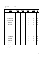
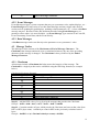
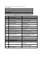
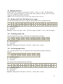
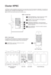
Quick Reference Guide
Feature
CAS44
CAA66
CAM6.6
CAV6.6
Pg.
Keypad Events
●
●
●
●
13
●
●
●
14
●
●
●
19
●
●
19
Source Control Events
Set Zone On/Off
●
Set All Zones On
Set All Zones Off
●
●
●
●
19
Zone Source
●
●
●
●
20
Zone Volume
●
●
●
●
21
Bass
●
●
●
●
22
Treble
●
●
●
●
23
Loudness
●
●
●
●
24
Balance
●
●
●
●
25
Turn On Volume
●
●
●
●
26
Background Color
●
●
27
Do Not Disturb
●
●
28
Party Mode
●
●
29
All Zone Info
○
○
●
●
30
Displaying a String
●
●
●
●
31
Display Messages
●
●
●
●
33
○= Partially Supported Feature
●= Fully Supported Feature
2
1
INTRODUCTION..............................................................................................................................................5
2
OVERVIEW .......................................................................................................................................................5
3
COM PORT........................................................................................................................................................5
3.1
3.2
4
COM S ETTINGS ........................................................................................................................................... 5
C ONNECTOR TYPE / P IN-OUT .......................................................................................................................5
RNET™ MESSAGE PACKET FORMAT......................................................................................................7
4.1
M ESSAGE HEADER ......................................................................................................................................7
4.1.1
Start of Message Character ...................................................................................................................7
4.1.2
Target Device ID ...................................................................................................................................7
4.1.2.1
4.1.2.2
4.1.2.3
4.1.3
Target Controller ID ............................................................................................................................................7
Target Zone (Port) ID ..........................................................................................................................................8
Target Keypad ID ................................................................................................................................................ 8
Source Device ID...................................................................................................................................9
4.1.3.1
4.1.3.2
4.1.3.3
Source Controller ID ...........................................................................................................................................9
Source Zone (Port) ID ......................................................................................................................................... 9
Source Keypad ID ............................................................................................................................................... 9
4.1.4
Message Type.........................................................................................................................................9
4.2
M ESSAGE B ODY ........................................................................................................................................10
4.2.1
The Invert Character ...........................................................................................................................10
4.2.2
Event Messages....................................................................................................................................11
4.2.3
Data Messages.....................................................................................................................................11
4.3
M ESSAGE TRAILER ....................................................................................................................................11
4.3.1
Checksum .............................................................................................................................................11
4.3.2
End of Message Character ..................................................................................................................12
5
BUTTONS AND KEYCODES........................................................................................................................13
5.1
5.2
KEYPAD EVENTS .......................................................................................................................................13
S OURCE CONTROL EVENTS .......................................................................................................................14
6
USING REQUEST MESSAGES ....................................................................................................................18
7
ZONES ..............................................................................................................................................................19
7.1
7.1.1
7.1.2
7.1.3
7.2
7.2.1
7.2.2
7.3
7.3.1
7.3.2
7.4
7.4.1
7.4.2
7.4.3
7.5
7.5.1
7.5.2
7.5.3
7.6
7.6.1
7.6.2
7.6.3
7.7
7.7.1
7.7.2
ON/OFF ....................................................................................................................................................19
Set State ...............................................................................................................................................19
Get State ..............................................................................................................................................19
Set All Zones On/Off State ...................................................................................................................19
S OURCE SELECT ........................................................................................................................................20
Set Source ............................................................................................................................................20
Get Source ...........................................................................................................................................20
VOLUME SELECT .......................................................................................................................................21
Set Volume ...........................................................................................................................................21
Get Volume ..........................................................................................................................................21
B ASS .........................................................................................................................................................22
Bass Up/Bass Down.............................................................................................................................22
Set Bass................................................................................................................................................22
Get Bass ...............................................................................................................................................22
TREBLE .....................................................................................................................................................23
Treble Up/Treble Down .......................................................................................................................23
Set Treble .............................................................................................................................................23
Get Treble ............................................................................................................................................23
LOUDNESS .................................................................................................................................................24
Loudness Toggle On/Off ......................................................................................................................24
Set Loudness ........................................................................................................................................24
Get Loudness .......................................................................................................................................24
B ALANCE ..................................................................................................................................................25
Balance Left or Balance Right.............................................................................................................25
Set Balance ..........................................................................................................................................25
3
7.7.3
Get Balance .........................................................................................................................................25
7.8
TURN ON VOLUME ....................................................................................................................................26
7.8.1
Increase or Decrease Turn On Volume ...............................................................................................26
7.8.2
Set Turn On Volume.............................................................................................................................26
7.8.3
Get Turn On Volume............................................................................................................................26
7.9
B ACKGROUND C OLOR ...............................................................................................................................27
7.9.1
Background Color Off/Amber/Green toggle........................................................................................27
7.9.2
Set Background Color..........................................................................................................................27
7.9.3
Get Background Color.........................................................................................................................27
7.10
DO NOT DISTURB ......................................................................................................................................28
7.10.1
Do Not Disturb On/Off Toggle........................................................................................................28
7.10.2
Set Do Not Disturb..........................................................................................................................28
7.10.3
Get Do Not Disturb.........................................................................................................................28
7.11
P ARTY MODE ............................................................................................................................................29
7.11.1
Party Mode On, Party Mode Master, and Party Mode Off.............................................................29
7.11.2
Set Party Mode................................................................................................................................29
7.11.3
Get Party Mode...............................................................................................................................29
7.12
GET ALL ZONE INFO ..................................................................................................................................30
7.12.1
Get State..........................................................................................................................................30
8
DISPLAYING A STRING ..............................................................................................................................31
8.1
8.2
9
ON ALL KEYPADS .....................................................................................................................................31
ON A SPECIFIC KEYPAD ............................................................................................................................31
DISPLAY MESSAGES ...................................................................................................................................33
9.1
9.2
9.3
R EADING DIRECT DISPLAY F EEDBACK .....................................................................................................33
R EADING SOURCE B ROADCAST DISPLAY FEEDBACK ................................................................................34
R EADING MULTI-F IELD B ROADCAST DISPLAY FEEDBACK M ESSAGES .....................................................35
10
USING THE ACKNOWLEDGE MESSAGE (HANDSHAKING) .............................................................35
11
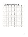
ASCII CHARACTER SET TO HEX CONVERSION CHART ..................................................................37
12
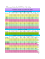
RUSSOUND CONTROLLERS RS-232 HEX CODE LISTING .................................................................38
4
1 Introduction
This document describes how to control and interpret data from Russound controllers. Remote
access is provided through the RS-232 serial port found on the front (CAV only) or rear of the
controller using the following RNET™ communications protocol. It is assumed that the reader
is familiar with the features and operation of the controller being used. All commands use
Hexadecimal or HEX values. In descriptive text these are indicated by preceding the value with a
0x. Zero-based values are also used in certain areas and are noted as such. This means that a
value of 0x00 = 1, 0x01 = 2, and 0x02 = 3 etc…Throughout this document all bytes within
message packets not in bold must be referenced exactly as they appear.
2 Overview
Russound controllers use a comprehensive communications protocol called RNET™ which has
been extended to the RS-232 port. Through this port, virtually all aspects of the device operation
can be performed. This document provides detailed descriptions of messages required to perform
basic device operation, as well as instructions on how to interpret display feedback messages.
3 COM Port
3.1 COM Settings
• 19200 baud rate
• 1 Start bit
• 1 Stop bit
• No flow control
• No parity
3.2 Connector Type / Pin-out
Connector: Female DB-9
• Pin 1: NC
• Pin 2: Transmit
• Pin 3: Receive
• Pin 4: NC
• Pin 5: Ground
• Pin 6: NC
• Pin 7: NC
• Pin 8: NC
• Pin 9: NC
5
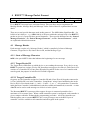
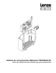
4 RNET™ Message Packet Format
0xF0
Header
Target Device ID
Source Device ID
Type
Body
Body
Trailer
Checksum
0xF7
Every RNET™ message has a consistent format. There are three major components; the
Message Header, Message Body and Message Trailer. Each of these is explained here in some
detail.
There are several special characters used in this protocol. The MSB (Most Significant Bit – far
left bit of an 8-bit byte – e.g., 0b00010001) of all bytes within the message body of an RNET™
packet are low (0), except for these special characters. These special characters are the “Start of
Message Character”, the “End of Message Character”, and the “Invert Character”, which
are explained within this document.
4.1 Message Header
Each message consists of a “Message Header” which is compiled of a Start of Message
Character, Target Device ID, Source Device ID, and the Message Type.
4.1.1 Start of Message Character
0xF0 is the special HEX value that indicates the beginning of a new message.
4.1.2 Target Device ID
The Target Device ID defines to which device we are sending the message. Every device on an
RNET™ system has a unique "Device ID" that allows messages to be sent to it. Each Device ID
consists of a Controller ID, a Zone (Port) ID and a Keypad ID. In the case of a Controller with
zone keypads, the purpose of each Device ID field is apparent.
4.1.2.1 Target Controller ID
On power up, the Controller assigns its Controller ID and a Zone ID to all keypads connected to
it. The Controller ID is set in the Controllers “Setup Menu” using 1 based numbering but in the
Device ID it is Zero-based (0x00 = 1, 0x01 = 2, 0x02 = 3, etc…). All systems have a controller
0x00 (the Root Controller) with additional controllers added (and numbered) as needed. A value
of 0x7F can be used to send messages to all devices in the system.
The Russound RNET™ system provides support for up to 6 connected controllers for a
maximum of 36 separate zones. When a multi-controller system is configured, each controller is
given a unique controller ID through the programming procedure. All of the controllers are
linked together onto a common RNET™ bus, so any messages sent to the RS232 port of
controller 1 will be available to all controllers and all keypads in the system.
7
All of the messages described in this document can be sent to any of the controllers in the system
by simply changing the Target Controller ID to match the controller you would like to send the
message to.
The following examples show the Volume Up command being sent to the same zone (Zone 1)
but on different controllers using Keypad Event messages:
Byte # 1 2 3 4 5 6 7 8 9 10 11 12 13 14 15 16 17 18 19 20 21
Value F0 00 00 7F 00 01 70 05 02 02 00 00 7F 00 00 00 00 00 01 7C F7
Byte # 1 2 3 4 5 6 7 8 9 10 11 12 13 14 15 16 17 18 19 20 21
Value F0 01 00 7F 00 01 70 05 02 02 00 00 7F 00 00 00 00 00 01 7D F7
Byte # 1 2 3 4 5 6 7 8 9 10 11 12 13 14 15 16 17 18 19 20 21
Value F0 05 00 7F 00 01 70 05 02 02 00 00 7F 00 00 00 00 00 01 01 F7
Byte #2 shows the Controller ID (Zero Based) that the message is being sent to.
NOTE: Remember to recalculate the checksum or the message will be rejected by the controller.
4.1.2.2 Target Zone (Port) ID
Zone ID defines the zone for a particular device. For keypads, this defines which zone port on
the Controllers rear panel that the keypad is connected to. The following special Zone ID values
have been defined:
Here is a list of special Target Zone (Port) ID values:
Value (Hex)
7F
7E
7D
7C
Description
Reserved
Controller Link
Peripheral Device (Internal Tuner, ST2-XM, etc...)
Trace
Aside from these values and those for the actual ports on the back of a controller, 0x00 – 0x03
for 4 zone controllers and 0x00 – 0x05 for 6 zone controllers, and 0x7D for a Peripheral Device,
any value can be used for the Zone ID field.
4.1.2.3 Target Keypad ID
Keypad ID identifies particular Keypads sharing a single zone on the controller or the Source
Number of an Internal Tuner (AM/FM or XM for CAM only) when the Zone ID is set as
Peripheral. For keypads, these are numbered 0x00 – 0x05. For Peripheral Tuners, these are also
numbered 0x00 – 0x05. The following values have specific meaning in the system:
Value (Hex)
7F
Description
The Controller Itself
8
7E
7D
Reserved
Targets all Keypads on a particular zone or all
Sources for connected Peripheral Devices
A special ID used by Keypads when they are
requesting an ID (Keypad ID) from the Controller
This message is a Source Broadcast Display
Feedback message
7C
79
All other keypad IDs have not been formally assigned so they can be used as needed.
4.1.3 Source Device ID
The “Source” Device ID is the identification of the device that is sending the message. For
external devices controlling the system, like an automation and control system, these can be any
value that is a unique value among devices attached to the system. The recommend Device ID
for external control systems is Controller ID: 0x00, Zone ID: 0x00, and Keypad ID: 0x70.
4.1.3.1 Source Controller ID
rd
For 3 party devices, this should be set to a value of ‘0x00’.
4.1.3.2 Source Zone (Port) ID
For 3rd party devices, this should be set to a unique value among devices attached to the system.
4.1.3.3 Source Keypad ID
The recommend Keypad ID for external control systems is 0x70, which is a Keypad ID other
than those used in the system.
4.1.4 Message Type
This value defines the type of message that is being sent. The most important Message Types are
as follows:
Value (Hex)
00
01
02
05
Message Type
Set Data
Request Data
Handshake
Event
Description
Sets a parameter’s value
Requests a parameter’s value
Acknowledges a data send
Triggers a system response that may
set a parameter value, update displays,
etc…
9
In some cases, setting parameter values can be done in two ways. A Set Data message can be
sent directly to the parameter, or an Event message can be sent to trigger the Controller to set the
value instead. Event messages are a little easier to use, and may trigger other desired results
(such as updating Keypad displays, updating related parameters, etc…) where a Set Data
message may not. Because of this, this document describes using Event messages to set
parameter values where it is most desirable.
4.2 Message Body
The message body contains specific data which varies in value and byte count depending on the
particular Message Type being sent. Refer to the particular messages.
4.2.1 The Invert Character
The Invert Character is used in special cases as part of the Message Body. If the data in an
RNET™ message body includes any byte values that have the MSB set to 1 (they have a Hex
value greater than 0x7F) the byte will be rejected as only the lower 7 bits are used to hold data.
In order to allow values greater than 0x7F to be accepted, the byte must first be bitwise inverted
(e.g., 10010101 = 01101010), and the special Invert Character (0xF1) is inserted just prior to
the inverted byte. When an RNET™ packet is received, the system must detect the 0xF1 invert
character. The 0xF1 character is then discarded and the following byte is inverted back to its
original value (e.g., 01101010 = 10010101).
Invert Character Usage Example:
Sent message with inverted character:
Value (Hex)
F0
00
67
7C
F1
6A
34
F7
Notes
Start of message character
Special Invert Character
Inverted Character (actual value 0x95)
Checksum
End of message character
Received message after re-inverting character:
Value (Hex)
F0
00
67
7C
95
XX
Notes
Start of message character
After re-inversion
Checksum (Discarded)
10
F7
End of message character
4.2.2 Event Messages
Event Messages trigger a system response that may set a parameter value, update displays, etc…
Event Messages are a little easier to use then Data Messages and may trigger other desired
results (such as updating Keypad displays, updating related parameters, etc…) where a Set Data
message may not. Because of this, this document describes using Event Messages to set
parameter values where it is most desirable. An Event Message Type consists of an Event ID,
Event Timestamp, Event Data, and the Event Priority.
4.2.3 Data Messages
A Set Data message can be sent directly to the parameter to set a parameter’s value.
4.3 Message Trailer
The Message Trailer consists of the Checksum and End of Message Character. The
Checksum value changes and needs to be re-calculated whenever any one of the preceding
characters in the message is changed. The Checksum is always followed by the End of
Message Character.
4.3.1 Checksum
All messages include a Checksum that helps protect the integrity of the message. The
Checksum is a single byte that can be calculated using the following formula (see example
below):
Checksum Calculation Example:
Value (Hex)
F0
00
67
7C
F1
0F
59
F7
Notes
Start of Message Character
Checksum
End of Message Character
Step #1 - Add the HEX value of every byte in the message that precedes the Checksum:
Example - 0xF0 + 0x00 + 0x67 + 0x7C + 0xF1 + 0x0F = 0x02D3
Step #2 - Count the number of bytes which precede the Checksum and convert that value from
DEC to HEX (byte count). Add the byte count in HEX to the previously calculated sum of
bytes:
Example - 0x02D3 + 6 (6 = Decimal value byte count) = 0x02D9
11
Step #3 - This value is then AND-ed with the HEX value 0x007F (7F is the highest BIN value
for 7 bits = 1111111). The Checksum itself and the End of Message Character are not
included in the calculation. Only the low 7 bits are used so overflow is discarded:
Example - 0x02D9 AND 0x007F = 0x59 = Checksum
4.3.2 End of Message Character
The End of Message Character (0xF7) is the special HEX value that indicates the end of the
message.
12
5
Buttons and Keycodes
This section describes how to send various events associated with the Buttons found on the
keypads and/or the IR remote
The method for transmitting these button events falls into two categories:
-Keypad Events: The Keypad Events are the events that the keypad is capable of sending.
-Source Control Events: All others (Source Control Events) are only available via the IR
Remote.
Note: all values are in HEX.
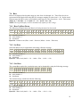
5.1 Keypad Events
Here is a list of UNO Keypad Event values and a description of which buttons they apply to:
Value (Hex)
64
67
68
69
6A
6B
6C
6D
6E
6F
70
73
7F
80
Description
Setup Button
Previous
Next
Plus
Minus
Source (source toggle button)
Power
Stop
Pause
Favorite 1
Favorite 2
Play
Volume Up
Volume Down (because this value is > 7F, the
special F1 character must be used)
Here are some examples of some Keypad Events:
Zone 1, Volume Up
F0 00 00 7F 00 00 70 05 02 02 00 00 7F 00 00 00 00 00 01 7B F7
Zone 2, Play
F0 00 00 7F 00 01 70 05 02 02 00 00 73 00 00 00 00 00 01 70 F7
Zone 3, Favorite 1
F0 00 00 7F 00 02 70 05 02 02 00 00 6F 00 00 00 00 00 01 6D F7
13
Here is a break out of the Zone1, Volume Up message (using above example of Keypad Event)
Value
F0
00
00
7F
00
00
70
Field
Start of Message
Target Controller ID
Target Zone ID
Target Keypad ID
Source Controller ID
Source Zone ID
Source Keypad ID
05
02
02
00
00
7F
00
00
00
00
00
01
Message Type
Target Path, Num Levels
Target Path, Level 1
Target Path, Level 2
Source Path, Num Levels
Event ID Lo Byte
Event ID Hi Byte
Event Timestamp Lo Byte
Event Timestamp Hi Byte
Event Data Lo Byte
Event Data Hi Byte
Event Priority
7B
Checksum
F7
End of Message
Description
Controller 1
The Controller itself
Zone affected
Arbitrary Keypad ID (not otherwise
used by the system
Event Message
Root Menu
Run Menu
No Source Path is used
Volume Up
unused
unused
unused
unused
Low Priority (does not generate a
handshake)
Recalculate when a preceding
byte value is changed
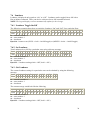
5.2 Source Control Events
Source Control Events are unique to the System Remote and are all sent using the special
“Remote Control Key” Event type with the actual Keycode passed in as the Data for the Event.
Here is a list of the Source Control Events (Keycodes):
Value (Hex)
01
02
03
04
Description
“1” Button
“2” Button
“3” Button
“4” Button
14
05
06
07
08
09
0A
0B
0C
0D
0E
0F
10
11
12
13
14
15
16
17
18
19
1A
1B
1C
1D
1E
1F
20
21
22
23
24
25
26
27
28
29
2A
“5” Button
“6” Button
“7” Button
“8” Button
“9” Button
“0” Button
Volume Up
Volume Down
Mute (for zone, not source)
Channel Up
Channel Down
Power
Enter
Previous Channel
TV/Video
TV/VCR
A/B
TV/DVD
TV/LD
Input
TV/DSS
Play
Stop
Search Forward
Search Rewind
Pause
Record
Menu
Menu Up
Menu Down
Menu Left
Menu Right
Select
Exit
Display
Guide
Page Up
Page Down
15
2B
2C
2D
2E
2F
30
31
32
33
34
35
36
37
38
39
3A
3B
3C
3D
3E
3F
40
41
42
43
44
45
46
47
48
49
4A
4B
Disk
Plus 10
Open/Close
Random
Track Forward
Track Reverse
Surround On/Off
Surround Mode
Surround Up
Surround Down
PIP
PIP Move
PIP Swap
Program
Sleep
On
Off
11
12
13
14
15
16
Bright
Dim
Close
Open
Stop 2
AM/FM
Cue
Disk Up
Disk Down
Info
16
Here are some examples of some Source Control Events:
Zone 1, Menu
F0 00 00 7F 00 00 70 05 02 02 00 00 F1 40 00 00 00 20 00 01 4E F7
Zone 2, Mute
F0 00 00 7F 00 01 70 05 02 02 00 00 F1 40 00 00 00 0D 00 01 3C F7
Zone 3, Record
F0 00 00 7F 00 02 70 05 02 02 00 00 F1 40 00 00 00 1F 00 01 49 F7
Here is a break out of the Zone1, Menu message used in the above example:
Value
F0
00
00
7F
00
00
70
Field
Start of Message
Target Controller ID
Target Zone ID
Target Keypad ID
Source Controller ID
Source Zone ID
Source Keypad ID
05
02
02
00
00
F1
40
Message Type
Target Path, Num Levels
Target Path, Level 1
Target Path, Level 2
Source Path, Num Levels
Invert
Event ID Lo Byte
00
00
00
20
00
01
Event ID Hi Byte
Event Timestamp Lo Byte
Event Timestamp Hi Byte
Event Data Lo Byte
Event Data Hi Byte
Event Priority
7B
Checksum
F7
End of Message
Description
Controller 1
The Controller itself
Zone affected
Arbitrary Keypad ID (not otherwise
used by the system
Event Message
Root Menu
Run Menu
No Source Path is used
Invert the next byte
40 = 0xBF inverted = Remote
Control Key Release
unused
unused
Menu (Keycode)
unused
Low Priority (does not generate a
handshake)
Recalculate when a preceding
byte value is changed
17
6 Using Request Messages
The Request Data message is used to receive parameter data from the Controller. This may be
used to receive Zone Power State, Volume Level, etc. When a Request Data message is sent to
the Controller, a Set Data message is generated by the Controller and sent back to the Request
Message sender. Since the Set Data message is of high priority, an Acknowledge message must
be sent back to the Controller to acknowledge it received the Request message. Failure to send
the Acknowledge message will result in a system delay of approximately 2.5 seconds. This is
due to the Controller trying to re-send the Data.
Data can be requested discretely for each zone parameter, or all of the Zone information can be
requested in a single message.
18
7 Zones
This section will provide information in regards to messages that only apply to Zone commands.
This will include controlling the Zones as well as sending Request messages to “Get” the State of
the Zones. Zero-based values are used for the Zone Numbers (i.e. 0 = 1, 1 = 2, and 2 = 3 etc…)
7.1 ON/OFF
The simplest way to explicitly turn a Zone On or turn a Zone Off is by using the discrete Zone
On/Off Event. The Event Data fields determine the Zone and On/Off state. This example shows
using the Zone On/Off Event message to execute a Zone On command for Zone 1 of Controller
1. Refer to the Buttons section for information on toggling zone On/Off (“Power” command
found under Keypad Events).
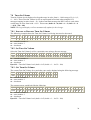
7.1.1 Set State
Turn a specific Zone ON or OFF using a discrete message.
Byte # 1 2 3 4 5 6 7 8 9 10 11 12 13 14 15 16 17 18 19 20 21 22
Value F0 cc 00 7F 00 00 70 05 02 02 00 00 F1 23 00 ## 00 zz 00 01 xx F7
cc = controller number -1
zz = zone number -1
xx = checksum
Byte #16 = 0x00 (off) or 0x01(on)
7.1.2 Get State
This is the Request message for the On/Off State of the selected Zone.
Byte # 1 2 3 4 5 6 7 8 9 10 11 12 13 14 15 16 17
Value F0 cc 00 7F 00 00 70 01 04 02 00 zz 06 00 00 xx F7
cc = controller number -1
zz = zone number -1
xx = checksum
The return message would look like the following.
Byte # 1 2 3 4 5 6 7 8 9 10 11 12 13 14 15 16 17 18 19 20 21 22 23
Value F0 00 00 70 cc 00 7F 00 00 04 02 00 zz 06 00 00 01 00 01 00 ## xx F7
cc = controller number -1
zz = zone number -1
xx = checksum
Byte #21 = 0x00 (off) or 0x01(on)
7.1.3 Set All Zones On/Off State
The RNET™ system can be sent a single message to issue an “All On” or “All Off” Event. The
Controllers have the ability to enable or disable the All On/All Off state control per zone. See
19
the Product Manual for instructions on programming each zone for “System On Enable” or
“System On Disable”.
Turn All Zones ON or OFF using a discrete message (all zones enabled in programming).
Byte # 1 2 3 4 5 6 7 8 9 10 11 12 13 14 15 16 17 18 19 20 21 22
Value F0 7E 00 7F 00 00 70 05 02 02 00 00 F1 22 00 00 ## 00 00 01 xx F7
xx = checksum
Byte #17 = 0x00 (all off) or 0x01(all on)
7.2 Source Select
The simplest way to explicitly select a Source per Zone is by using the discrete Source Select
Event. The Event Data fields determine the Source being selected. Refer to the Buttons section
for information on stepping through Sources (“Source Toggle” command found under Keypad
Events). Zero-based values are used for the Source Numbers (i.e. 0 = 1, 1 = 2, and 2 = 3 etc…)
7.2.1 Set Source
Select the Source for a particular zone using a discrete message.
Byte # 1 2 3 4 5 6 7 8 9 10 11 12 13 14 15 16 17 18 19 20 21 22
Value F0 cc 00 7F 00 zz 70 05 02 00 00 00 F1 3E 00 00 00 ## 00 01 xx F7
cc = controller number -1
zz = zone number -1
xx = checksum
Byte #18 = selected source number -1
7.2.2 Get Source
This is the Request message for what Source is selected on a particular Zone.
Byte # 1 2 3 4 5 6 7 8 9 10 11 12 13 14 15 16 17
Value F0 cc 00 7F 00 00 70 01 04 02 00 zz 02 00 00 xx F7
cc = controller number -1
zz = zone number -1
xx = checksum
The return message would look like the following.
Byte # 1 2 3 4 5 6 7 8 9 10 11 12 13 14 15 16 17 18 19 20 21 22 23
Value F0 00 00 70 cc 00 7F 00 00 04 02 00 zz 02 00 00 01 00 01 00 ## xx F7
cc = controller number -1
zz = zone number -1
xx = checksum
Byte #21 = source number -1
20
7.3 Volume Select
The simplest way to explicitly select a Volume level per Zone is by using the discrete Volume
Select Event. The Even Timestamp fields determine the Volume Level. The Event Data fields
determine the Zone affected by the Volume being selected. Refer to the Buttons section for
information on stepping through Volume levels (“Volume Up” and “Volume Down” commands
found under UNO Keypad Events). Volume levels displayed on UNO keypads range in value
from 0 – 100 in steps of 2 (i.e. 0, 2, 4, 6, etc…). These Volume levels are represented in
Decimal when using RS-232 messages ranging in value from 0 – 50 (i.e. 0 = 0, 1 = 2, … 2 = 4).
In the actual Data message the HEX value is used which would range in value from 0x00 – 0x32.
This means (0x00 = 0 = 0, 0x01 = 1 = 2, 0x02 = 2 = 4 … 0x32 = 50 = 100)
7.3.1 Set Volume
Select the Volume for a particular zone using a discrete message.
Byte # 1 2 3 4 5 6 7 8 9 10 11 12 13 14 15 16 17 18 19 20 21 22
Value F0 cc 00 7F 00 00 70 05 02 02 00 00 F1 21 00 ## 00 zz 00 01 xx F7
cc = controller number -1
zz = zone number -1
xx = checksum
Byte #16 = volume level (0x00 - 0x32, 0x00 = 0 Displayed … 0x32 = 100 Displayed)
7.3.2 Get Volume
This is the Request message for what Volume level is selected on a particular Zone.
Byte # 1 2 3 4 5 6 7 8 9 10 11 12 13 14 15 16 17
Value F0 cc 00 7F 00 00 70 01 04 02 00 zz 01 00 00 xx F7
cc = controller number -1
zz = zone number -1
xx = checksum
The return message would look like the following.
Byte # 1 2 3 4 5 6 7 8 9 10 11 12 13 14 15 16 17 18 19 20 21 22 23
Value F0 00 00 70 cc 00 7F 00 00 04 02 00 zz 01 00 00 01 00 01 00 ## xx F7
cc = controller number -1
zz = zone number -1
xx = checksum
Byte #21 = Volume Level -1
21
7.4 Bass
Bass levels displayed on keypads range in value from -10 through +10. These Bess levels are
represented in Decimal when using RS-232 messages ranging in value from 0 - 20. In the actual
Data message the HEX value is used which would range in value from 0x00 – 0x14. This means
(0x00 = 0 = -10, 0x01 = 1 = -9, 0x02 = 2 = -8 … 0x14 = 20 = +10).
NOTE: The keypad displays will not automatically update for this change.
7.4.1 Bass Up/Bass Down
The following example shows the Bass level being increased or decreased.
Byte # 1 2 3 4 5 6 7 8 9 10 11 12 13 14 15 16 17 18 19 20 21 22 23 24
Value F0 cc 00 7F 00 00 70 05 05 02 00 zz 00 00 00 ## 00 00 00 00 00 01 xx F7
cc = controller number -1
zz = zone number -1
xx = checksum
Byte #16 = button event (Plus = 0x69 = Increase, Minus = 0x6A = Decrease)
7.4.2 Set Bass
Select the Bass level for a particular zone using a discrete message.
Byte # 1 2 3 4 5 6 7 8 9 10 11 12 13 14 15 16 17 18 19 20 21 22 23 24
Value F0 cc 00 7F 00 00 70 00 05 02 00 zz 00 00 00 00 00 01 00 01 00 ## xx F7
cc = controller number -1
zz = zone number -1
xx = checksum
Byte #22 = Bass level (0x00 = -10 … 0x0A = Flat … 0x14 = +10)
7.4.3 Get Bass
The current Bass setting for a particular zone can be obtained by using the following message.
Byte # 1 2 3 4 5 6 7 8 9 10 11 12 13 14 15 16 17 18
Value F0 cc 00 7F 00 00 70 01 05 02 00 zz 00 00 00 00 xx F7
cc = controller number -1
zz = zone number -1
xx = checksum
The return message would look like the following.
Byte # 1 2 3 4 5 6 7 8 9 10 11 12 13 14 15 16 17 18 19 20 21 22 23 24
Value F0 00 00 70 cc 00 7F 00 00 05 02 00 zz 00 00 00 00 01 00 01 00 ## xx 7F
cc = controller number -1
zz = zone number -1
xx = checksum
Byte #22 = Bass level (0x00 = -10 … 0x0A = Flat … 0x14 = +10)
22
7.5 Treble
Treble levels displayed on keypads range in value from -10 through +10. These Treble levels are
represented in Decimal when using RS-232 messages ranging in value from 0 - 20. In the actual
Data message the HEX value is used which would range in value from 0x00 – 0x14. This means
(0x00 = 0 = -10, 0x01 = 1 = -9, 0x02 = 2 = -8 … 0x14 = 20 = +10).
NOTE: The keypad displays will not automatically update for this change.
7.5.1 Treble Up/Treble Down
The following example shows the Treble level being increased or decreased.
Byte # 1 2 3 4 5 6 7 8 9 10 11 12 13 14 15 16 17 18 19 20 21 22 23 24
Value F0 cc 00 7F 00 00 70 05 05 02 00 zz 00 01 00 ## 00 00 00 00 00 01 xx F7
cc = controller number -1
zz = zone number -1
xx = checksum
Byte #16 = button event (Plus = 0x69 = Increase, Minus = 0x6A = Decrease)
7.5.2 Set Treble
Select the Treble level for a particular zone using a discrete message.
Byte # 1 2 3 4 5 6 7 8 9 10 11 12 13 14 15 16 17 18 19 20 21 22 23 24
Value F0 cc 00 7F 00 00 70 00 05 02 00 zz 00 01 00 00 00 01 00 01 00 ## xx F7
cc = controller number -1
zz = zone number -1
xx = checksum
Byte #22 = Treble level (0x00 = -10 … 0x0A = Flat … 0x14 = +10)
7.5.3 Get Treble
The current Treble setting for a particular zone can be obtained by using the following message.
Byte # 1 2 3 4 5 6 7 8 9 10 11 12 13 14 15 16 17 18
Value F0 cc 00 7F 00 00 70 01 05 02 00 zz 00 01 00 00 xx F7
cc = controller number -1
zz = zone number -1
xx = checksum
The return message would look like the following.
Byte # 1 2 3 4 5 6 7 8 9 10 11 12 13 14 15 16 17 18 19 20 21 22 23 24
Value F0 00 00 70 cc 00 7F 00 00 05 02 00 zz 00 01 00 00 01 00 01 00 ## xx F7
cc = controller number -1
zz = zone number -1
xx = checksum
Byte #22 = Treble level (0x00 = -10 … 0x0A = Flat … 0x14 = +10)
23
7.6 Loudness
Loudness is displayed on keypads as “On” or “Off”. Loudness can be toggled On or Off with a
Plus or Minus command. There can also be a discrete On or Off command selected.
NOTE: The keypad displays will not automatically update for this change.
7.6.1 Loudness Toggle On/Off
The following example shows how to toggle the Loudness “On” and “Off” for a particular Zone.
Byte # 1 2 3 4 5 6 7 8 9 10 11 12 13 14 15 16 17 18 19 20 21 22 23 24
Value F0 cc 00 7F 00 00 70 05 05 02 00 zz 00 02 00 ## 00 00 00 00 00 01 xx F7
cc = controller number -1
zz = zone number -1
xx = checksum
Byte #16 = button event (PLUS = 0x69 = On/Off toggle) or (MINUS = 0x6A = On/Off toggle)
7.6.2 Set Loudness
Turn Loudness On or Off for a particular zone using a discrete message.
Byte # 1 2 3 4 5 6 7 8 9 10 11 12 13 14 15 16 17 18 19 20 21 22 23 24
Value F0 cc 00 7F 00 00 70 00 05 02 00 zz 00 02 00 00 00 01 00 01 00 ## xx F7
cc = controller number -1
zz = zone number -1
xx = checksum
Byte #22 = Loudness setting (0x00 = OFF, 0x01 = ON )
7.6.3 Get Loudness
The current Loudness setting for a particular zone can be obtained by using the following
message.
Byte # 1 2 3 4 5 6 7 8 9 10 11 12 13 14 15 16 17 18
Value F0 cc 00 7F 00 00 70 01 05 02 00 zz 00 02 00 00 xx F7
cc = controller number -1
zz = zone number -1
xx = checksum
The return message would look like the following.
Byte # 1 2 3 4 5 6 7 8 9 10 11 12 13 14 15 16 17 18 19 20 21 22 23 24
Value F0 00 00 70 cc 00 7F 00 00 05 02 00 zz 00 02 00 00 01 00 01 00 ## xx F7
cc = controller number -1
zz = zone number -1
xx = checksum
Byte #22 = Loudness setting (0x00 = OFF, 0x01 = ON )
24
7.7 Balance
Balance levels displayed on keypads range in value from “Left 10” to “Center” to “Right 10”.
These Balance levels are represented in Decimal when using RS-232 messages ranging in value
from 0 - 20. In the actual Data message the HEX value is used which would range in value from
0x00 – 0x14. This means (0x00 = 0 = Left 10 … 0x0A = 10 = Center … 0x14 = 20 = Right
10).
NOTE: The keypad displays will not automatically update for this change.
7.7.1 Balance Left or Balance Right
The following example shows the Balance level being drawn More Left or More Right.
Byte # 1
2
3
4
5 6
7 8
9 10 11 12 13 14 15 16 17 18 19 20 21 22 23 24
Value F0 cc 00 7F 00 00 70 05 05 02 00 zz 00 03 00 ## 00 00 00 00 00 01 xx F7
cc = controller number -1
zz = zone number -1
xx = checksum
Byte #16 = button event (Plus = 0x69 = More Left, Minus = 0x6A = More Right)
7.7.2 Set Balance
Select the Balance level for a particular zone using a discrete message.
Byte # 1 2 3 4 5 6 7 8 9 10 11 12 13 14 15 16 17 18 19 20 21 22 23 24
Value F0 cc 00 7F 00 00 70 00 05 02 00 zz 00 03 00 00 00 01 00 01 00 ## xx F7
cc = controller number -1
zz = zone number -1
xx = checksum
Byte #22 = Balance level (0x00 = More Left … 0x0A = Center … 0x14 = More Right)
7.7.3 Get Balance
The current Balance setting for a particular zone can be obtained using the following message.
Byte # 1 2 3 4 5 6 7 8 9 10 11 12 13 14 15 16 17 18
Value F0 cc 00 7F 00 00 70 01 05 02 00 zz 00 03 00 00 xx F7
cc = controller number -1
zz = zone number -1
xx = checksum
The return message would look like the following.
Byte # 1 2 3 4 5 6 7 8 9 10 11 12 13 14 15 16 17 18 19 20 21 22 23 24
Value F0 00 00 70 cc 00 7F 00 00 05 02 00 zz 00 03 00 00 01 00 01 00 ## xx F7
cc = controller number -1
zz = zone number -1
xx = checksum
Byte #22 = Balance level (0x00 = More Left … 0x0A = Center … 0x14 = More Right)
25
7.8 Turn On Volume
Turn On Volume levels displayed on keypads range in value from 0 – 100 in steps of 2 (i.e. 0, 2,
4 … 100). These Turn On Volume levels are represented in Decimal when using RS-232
messages ranging in value from 0 - 50. In the actual Data message the HEX value is used which
would range in value from 0x00 – 0x32. This means (0x00 = 0 = 0, 0x01 = 1 = 2, 0x02 = 2 = 4
… 0x32 = 50 = 100)
NOTE: The keypad displays will not automatically update for this change.
7.8.1 Increase or Decrease Turn On Volume
The following example shows the Turn On Volume level being increased or decreased.
Byte # 1
2
3
4
5 6
7 8
9 10 11 12 13 14 15 16 17 18 19 20 21 22 23 24
Value F0 cc 00 7F 00 00 70 05 05 02 00 zz 00 04 00 bb 00 00 00 00 00 01 xx F7
cc = controller number -1
zz = zone number -1
xx = checksum
7.8.2 Set Turn On Volume
Select the Turn On Volume level for a particular zone using a discrete message.
Byte # 1 2 3 4 5 6 7 8 9 10 11 12 13 14 15 16 17 18 19 20 21 22 23 24
Value F0 cc 00 7F 00 00 70 00 05 02 00 zz 00 04 00 00 00 01 00 01 00 ## xx F7
cc = controller number -1
zz = zone number -1
xx = checksum
Byte #22 = Turn On Volume level (0x00 - 0x32, 0x00 = 0 … 0x32 = 100)
7.8.3 Get Turn On Volume
The current Turn On Volume for a particular zone can be obtained using the following message.
Byte # 1 2 3 4 5 6 7 8 9 10 11 12 13 14 15 16 17 18
Value F0 cc 00 7F 00 00 70 01 05 02 00 zz 00 04 00 00 xx F7
cc = controller number -1
zz = zone number -1
xx = checksum
The return message would look like the following.
Byte # 1 2 3 4 5 6 7 8 9 10 11 12 13 14 15 16 17 18 19 20 21 22 23 24
Value F0 00 00 70 cc 00 7F 00 00 04 02 00 zz 01 00 00 00 01 00 01 00 ## xx F7
cc = controller number -1
zz = zone number -1
xx = checksum
Byte #22 = Turn On Volume level (0x00 - 0x32, 0x00 = 0 … 0x32 = 100)
26
7.9 Background Color
Background Color is displayed on keypads as “Amber”, “Green”, or “Off”. The Background
Color can be toggled through these selections with a Plus or Minus command. There can also be
a discrete command selected for each choice.
NOTE: The keypad displays WILL automatically update for this selection.
7.9.1 Background Color Off/Amber/Green toggle
The following example shows how to toggle the Background Color for a particular Zone.
Byte # 1
2
3
4
5 6 7 8
9 10 11 12 13 14 15 16 17 18 19 20 21 22 23 24
Value F0 00 00 7F 00 00 70 05 05 02 00 zz 00 05 00 ## 00 00 00 00 00 01 xx F7
cc = controller number -1
zz = zone number -1
xx = checksum
Byte #16 = button event (Plus = 0x69 = Off/Color toggle) or (Minus = 0x6A = Off/Color toggle)
7.9.2 Set Background Color
Select the Background Color for a particular zone using a discrete message.
Byte # 1 2 3 4 5 6 7 8 9 10 11 12 13 14 15 16 17 18 19 20 21 22 23 24
Value F0 00 00 7F 00 00 70 00 05 02 00 zz 00 05 00 00 00 01 00 01 00 ## xx F7
cc = controller number -1
zz = zone number -1
xx = checksum
Byte #22 = Background Color (0x00 = Off, 0x01 = Amber, 0x02 = Green)
7.9.3 Get Background Color
The current Background Color for a particular zone can be obtained using the following
message.
Byte # 1 2 3 4 5 6 7 8 9 10 11 12 13 14 15 16 17 18
Value F0 cc 00 7F 00 00 70 01 05 02 00 zz 00 05 00 00 xx F7
cc = controller number -1
zz = zone number -1
xx = checksum
The return message would look like the following.
Byte # 1 2 3 4 5 6 7 8 9 10 11 12 13 14 15 16 17 18 19 20 21 22 23 24
Value F0 00 00 70 cc 00 7F 00 00 05 02 00 zz 00 05 00 00 01 00 01 00 ## xx F7
cc = controller number -1
zz = zone number -1
xx = checksum
Byte #22 = Background Color (0x00 = Off, 0x01 = Amber, 0x02 = Green)
27
7.10 Do Not Disturb
Do Not Disturb is displayed on keypads as “On” or “Off”. DND can be toggled On or Off with a
Plus or Minus command. There can also be a discrete On or Off command selected.
7.10.1 Do Not Disturb On/Off Toggle
The following example shows how to toggle Do Not Disturb “On” and “Off” for a particular
Zone.
Byte # 1 2 3 4 5 6 7 8 9 10 11 12 13 14 15 16 17 18 19 20 21 22 23 24
Value F0 00 00 7F 00 00 70 05 05 02 00 zz 00 06 00 ## 00 00 00 00 00 01 xx F7
cc = controller number -1
zz = zone number -1
xx = checksum
Byte #16 = button event (Plus = 0x69 = On/Off toggle) or (Minus = 0x6A = On/Off toggle)
7.10.2 Set Do Not Disturb
Turn DND On or Off for a particular zone using a discrete message.
Byte # 1 2 3 4 5 6 7 8 9 10 11 12 13 14 15 16 17 18 19 20 21 22 23 24
Value F0 00 00 7F 00 00 70 00 05 02 00 zz 00 06 00 00 00 01 00 01 00 ## xx F7
cc = controller number -1
zz = zone number -1
xx = checksum
Byte #22 = Do Not Disturb setting (0x00 = OFF, 0x01 = ON )
7.10.3 Get Do Not Disturb
The current DND setting for a particular zone can be obtained by using the following message.
Byte # 1 2 3 4 5 6 7 8 9 10 11 12 13 14 15 16 17 18
Value F0 cc 00 7F 00 00 70 01 05 02 00 zz 00 06 00 00 xx F7
cc = controller number -1
zz = zone number -1
xx = checksum
The return message would look like the following.
Byte # 1 2 3 4 5 6 7 8 9 10 11 12 13 14 15 16 17 18 19 20 21 22 23 24
Value F0 00 00 70 cc 00 7F 00 00 05 02 00 zz 00 06 00 00 01 00 01 00 ## xx F7
cc = controller number -1
zz = zone number -1
xx = checksum
Byte #22 = Do Not Disturb setting (0x00 = OFF, 0x01 = ON )
28
7.11 Party Mode
Party Mode is displayed on keypads as “On”, “Off”, or “Master”. Party Mode can be toggled to
“On” or “Master” with the Plus command. The Minus command will toggle Party Mode “Off”.
There can also be a discrete On, Off, or Master command sent.
7.11.1Party Mode On, Party Mode Master, and Party Mode Off
NOTE: If Party Mode is Off, then “Plus” will issue a “Master” command. If a Zone is turned
on while the rest of the system has Party Mode On and a different Zone is the Master, then
“Plus” from a non-active Zone will issue an “On” command first and then a “Master”
command second. If Party Mode is On and a different Zone is Master, then “Plus” from an
active zone will issue a “Master” command. Minus will always issue an “Off” command.
The following example shows how to toggle Party Mode for a particular Zone.
Byte # 1 2 3 4 5 6 7 8 9 10 11 12 13 14 15 16 17 18 19 20 21 22 23 24
Value F0 00 00 7F 00 00 70 05 05 02 00 zz 00 07 00 ## 00 00 00 00 00 01 xx F7
cc = controller number -1
zz = zone number -1
xx = checksum
Byte #16 = button event (Plus = 0x69 = On/Off toggle) or (Minus = 0x6A = On/Off toggle)
7.11.2 Set Party Mode
Select Party Mode “Master”, “On”, or “Off” for a particular zone using a discrete message.
Byte # 1 2 3 4 5 6 7 8 9 10 11 12 13 14 15 16 17 18 19 20 21 22 23 24
Value F0 00 00 7F 00 00 70 00 05 02 00 zz 00 07 00 00 00 01 00 01 00 ## xx F7
cc = controller number -1
zz = zone number -1
xx = checksum
Byte #22 = Party Mode setting (0x00 = OFF, 0x01 = ON, 0x02 = Master)
7.11.3 Get Party Mode
The current Party Mode state for a particular zone can be obtained using the following message.
Byte # 1 2 3 4 5 6 7 8 9 10 11 12 13 14 15 16 17 18
Value F0 cc 00 7F 00 00 70 01 05 02 00 zz 00 07 00 00 xx F7
cc = controller number -1
zz = zone number -1
xx = checksum
The return message would look like the following.
Byte # 1 2 3 4 5 6 7 8 9 10 11 12 13 14 15 16 17 18 19 20 21 22 23 24
Value F0 00 00 70 cc 00 7F 00 00 05 02 00 zz 00 07 00 00 01 00 01 00 ## xx F7
cc = controller number -1
zz = zone number -1
xx = checksum
Byte #22 = Party Mode setting (0x00 = OFF, 0x01 = ON, 0x02 = Master)
29
7.12 Get All Zone info
As stated previously, a message can be used to request all of a particular Zone's parameter values
at once. This can be very useful for updating panel displays. The following is an example of
how to request Zone information for a particular Zone and what the return message would look
like.
7.12.1 Get State
This is the Request message for the parameter values of the selected Zone.
Byte # 1 2 3 4 5 6 7 8 9 10 11 12 13 14 15 16 17
Value F0 cc 00 7F 00 00 70 01 04 02 00 zz 07 00 00 xx F7
cc = controller number -1
zz = zone number -1
xx = checksum
The return message would look like the following.
Byte # 1 2 3 4 5 6 7 8 9 10 11 12 13 14 15 16 17 18 19 20 21 22 23
Value F0 00 00 70 cc 00 7F 00 00 04 02 00 zz 07 00 00 01 00 0C 00 ## ## ##
Byte # 24 25 26 27 28 29 30 31 32 33 34
Value ## ## ## ## ## ## ## ## 00 xx F7
cc = controller number -1
zz = zone number -1
xx = checksum
The parameter values are depicted in bytes 21 – 31. These values will change depending on the
state of the selected Zone. The above example shows the parameter values for a Zone
configured and being used as follows:
Byte #21 = Current Zone On/Off state (0x00 = OFF or 0x01 = ON)
Byte #22 = Current Source selected -1
Byte #23 = Current Volume level (0x00 - 0x32, 0x00 = 0 Displayed … 0x32 = 100 Displayed)
Byte #24 = Current Bass level (0x00 = -10 … 0x0A = Flat … 0x14 = +10)
Byte #25 = Current Treble level (0x00 = -10 … 0x0A = Flat … 0x14 = +10)
Byte #26 = Current Loudness (0x00 = OFF, 0x01 = ON )
Byte #27 = Current Balance level (0x00 = More Left … 0x0A = Center … 0x14 = More Right)
Byte #28 = Current System On state (0x00 = All Zones Off, 0x01 = Any Zone is On)
Byte #29 = Current Shared Source (0x00 = Not Shared 0x01 = Shared with another Zone)
Byte #30 = Current Party Mode state (0x00 = OFF, 0x01 = ON, 0x02 = Master)*
Byte #31 = Current Do Not Disturb state (0x00 = OFF, 0x01 = ON )*
*NOTE: Unsupported Features, information not available for CAS44 and CAA66 controllers
30
8 Displaying a String
Since the keypad contains a text display, we’ve provided a message that will allow you to send
text messages to All Keypads simultaneously or a Specific Keypad individually.
“Alignment” – When sending a message to display text on a Keypad the first Data byte sets
your Alignment (0x00 = Centered, 0x01 = Left justified).
“Flash Time” – Messages can be displayed constant or they can be flashed on the display for a
brief time. When sending a message to display text on a Keypad the second and third Data bytes
set the Flash Time. Flash Time defines how long the string is displayed. This is measured in
10ms increments with a value of 0x00 being constant.
“Null character” – A value of 0x00 used as a Data byte will be a text character of Null. A Null
text character is always used after the last text character in the display string. With a 12
th
character text message you would use a Null character as the 13 text character. A Null
character is also used for each unused text character at the end of the text display message if the
maximum number of Data bytes are not all used.
8.1 On All Keypads
The following example shows how to display a text message on All Keypads (or other devices
with a text display) in the system.
Byte # 1 2 3 4 5 6 7 8 9 10 11 12 13 14 15 16 17 18 19 20 21 22 23 24
Value F0 7F 00 00 00 00 70 00 02 01 01 00 00 00 01 00 10 00 ## ## ## ## ## ##
Byte # 25 26 27 28 29 30 31 32 33 34 35 36
Value ## ## ## ## ## ## ## ## ## ## xx F7
cc = Controller Number -1 (0x7F = All Devices = All Keypads)
zz = Zone Number -1
kk = Keypad Number -1
xx = Checksum
Byte #19 = Alignment (0x00 = Centered, 0x01 = Left justified)
Byte #20 = Low Byte of Flash Time
Byte #21 = High Byte of Flash Time
Byte #22 – #34 = ASCII text characters (Section 11 ASCII Character Set)
8.2 On A Specific Keypad
The following example shows how to display a text message on a Specific Keypad in the system.
This is accomplished by setting the Target Device ID for the particular keypad in question.
Byte # 1 2 3 4 5 6 7 8 9 10 11 12 13 14 15 16 17 18 19 20 21 22 23 24
Value F0 cc zz kk 00 00 70 00 02 01 01 00 00 00 01 00 10 00 ## ## ## ## ## ##
Byte # 25 26 27 28 29 30 31 32 33 34 35 36
Value ## ## ## ## ## ## ## ## ## ## xx F7
cc = Controller Number -1
zz = Zone Number -1
kk = Keypad Number -1
xx = Checksum
31
Byte #19 = Alignment (0x00 = Centered, 0x01 = Left justified)
Byte #20 = Low Byte of Flash Time
Byte #21 = High Byte of Flash Time
Byte #22 – #34 = ASCII text characters (Section 11 ASCII Character Set)
9 Display Messages
The following section describes how to read Display Messages. These include Direct Display
Feedback messages, Source Broadcast Display Feedback messages, and Multi-Field Broadcast
Display Feedback messages.
NOTE: In order to fully support the display capabilities, Direct Display feedback messages,
Source Broadcast Feedback messages and Multi-Field Broadcast Messages, should be
supported. (Multi-Field Broadcast messages are only used with XM.)
9.1
Reading Direct Display Feedback
This section describes how to read Direct Display Feedback Messages. These Feedback
messages are usually sent in direct response to a received command (e.g., If the current
frequency of a Russound tuner is “102.7 MHz FM”, sending the “Frequency Up” command will
trigger the Tuner to send a Display message back to the sender to update the frequency Display
to "102.9 MHz FM"). The Direct Display Feedback message is sent directly to the Target
Device ID of the message sender. The message can be displayed for a constant amount of time,
or a "Flash" display with a specified length of time (Flash Time is in increments of 10ms).
NOTE: It is possible that some display messages will include the special "Invert" control
character (0xF1).
NOTE: Some of the other bytes within this message may vary. Only the ones necessary to
interpret the message are highlighted.
NOTE: This message shows a text payload of 16 characters. Some devices may have a text
payload of 12 characters.
This is what the Direct Display Feedback message would look like using the above example.
Byte # 1 2 3 4 5 6 7 8 9 10 11 12 13 14 15 16 17 18 19 20 21 22 23 24
Value F0 00 00 70 00 7D 00 00 02 01 01 02 01 01 00 00 01 00 14 00 01 00 00 31
Byte # 25 26 27 28 29 30 31 32 33 34 35 36 37 38 39 40 41 42
Value 30 32 2E 39 20 4D 48 7A 20 46 4D 00 00 00 00 00 7F F7
Byte #2 – #4 = Target Device ID (This message should be displayed if the target Device ID
matches the Device ID of your device.)
Byte #19 = Overall Payload Size
Byte #22 = Flash Time low byte (Flash time is in 10ms increments, 0x00 = Constant)
Byte #23 = Flash Time high byte
Byte #24 – #40 = Text (“102.9 MHz FM” used in above example)
Byte #41 = Calculated Checksum
33
9.2
Reading Source Broadcast Display Feedback
This section describes how to read Source Broadcast Display Feedback messages. These
Feedback messages are sent to update all devices monitoring a given Source’s status. These
messages may be sent as a direct result of a sent command or as a general update. The Display
Feedback message is sent with the source number of the Source attached. The attached source
number indicates which Source the update is intended. The message can be displayed for a
constant amount of time, or a "Flash" display with a specified length of time (Flash Time is in
increments of 10ms).
NOTE: It is possible that some display messages will include the special "Invert" control
character (0xF1).
NOTE: Some of the other bytes within this message may vary. Only the ones necessary to
interpret the message are highlighted.
NOTE: This message shows a text payload of 16 characters. Some devices may have a text
payload of 12 characters.
This example shows a Source Broadcast Display Feedback message with text "102.9 MHz FM".
Byte # 1 2 3 4 5 6 7 8 9 10 11 12 13 14 15 16 17 18 19 20 21 22 23 24
Value F0 7D 00 79 00 7D 00 00 02 01 01 02 01 01 00 00 01 00 14 00 10 00 00 31
Byte # 25 26 27 28 29 30 31 32 33 34 35 36 37 38 39 40 41 42
Value 30 32 2E 39 20 4D 48 7A 20 46 4D 00 00 00 00 00 14 F7
Byte #4 = Target Keypad ID (NOTE: A value of 0x79 in the Target Keypad ID field indicates
that this message is a Source Broadcast Display Feedback message.)
Byte #19 = Overall Payload Size
Byte #21 = Message type and Source Number = (0x10 (Source Broadcast Display Type) bit-wise
OR-ed with the source number (e.g. source 1 = 0x10, source 3 = 0x12))
Byte #22 = Flash Time low byte (Flash time is in 10ms increments, 0x00 = Constant)
Byte #23 = Flash Time high byte
Bytes #24 – #40 = Text ("102.9 MHz FM")
Byte #41 = Calculated Checksum
34
9.3
Reading Multi-Field Broadcast Display Feedback Messages
Multi-Field Broadcast Display Feedback messages are sent to update all devices monitoring the
Source’s status. These Feedback messages are sent to update all devices monitoring a given
Source’s status. These messages may be sent as a direct result of a sent command or as a general
update. The Display Feedback message is sent with the source number of the Source attached.
A “Field ID” is included with the message to indicate which item is being updated (see table
below). The message can be displayed for a constant amount of time, or a "Flash" display with a
specified length of time (Flash Time is in increments of 10ms).
This example shows a Multi-Field Broadcast Display Feedback message text "49: Fine Tuning".
Byte # 1 2 3 4 5 6 7 8 9 10 1 1 12 13 14 15 16 17 18 19 20 21 22 2 3 24
Value F0 7D 00 79 00 7D 00 0 0 02 01 0 1 02 01 01 00 00 01 00 14 00 20 07 1C 34
Byte # 25 2 6 27 28 29 3 0 31 3 2 33 34 3 5 36 37 38 39 40 41 4 2
Value 39 3A 46 69 6E 6 5 54 7 5 6E 69 6E 67 00 00 00 00 09 F 7
Byte #4 = Target Keypad ID (NOTE: A value of 0x79 in the Target Keypad ID field indicates
that this message is a Source Broadcast Display Feedback message.)
Byte #19 = Overall Payload Size
Byte #21 = Message type and Source Number = (0x20 (Multi-Field Display Type) bit-wise ORed with the source number (e.g., source 1 = 0x20, source 3 = 0x22.))
Byte #22 = Field ID bit and Flash Bit = (bits 0 – 6 = Field Id (i.e., 0x07 = 7 = Channel Name),
Bit 7 – Ignore. Invert control character (0xF1) will be inserted before this byte if Bit 7 is set.
Bytes #24 – #40 = Text (“49: Fine Tuning”)
Byte #41 = Calculated Checksum
10 Using the Acknowledge Message (Handshaking)
When the controller sends a Return message in response to a Request message, the sender of the
Request message must send an Acknowledge message in response to the Return message.
Failure to send the Acknowledge message will result in a system delay of approximately 2.5
seconds while the controller tries to re-send the data. The controller will also send an
Acknowledge message in response to a Set Data message that it is sent. It is not necessary to
process the incoming Acknowledge message from the controller.
NOTE: A Peripheral Source does not require Handshaking when the keypad ID used to send
data is 0x70. If using a keypad ID of 0x70, and therefore no Handshaking, it is best to leave
approximately 100ms between messages to ensure that all messages are processed correctly. If
Handshaking is desired, it is recommended to use a keypad ID of 0x60. In this case, the
Peripheral Source will send an Acknowledge message in response to any high priority event
messages sent. Acknowledge messages can be (and normally are) used to trigger the release of
any additional messages that may be in the sender's queue.
This example shows sending a Frequency Up (Tune Up) event to a Russound Tuner: In this case
the event priority byte is set to 0x00 (high) and the sender Keypad ID is 0x60. This means that
the Internal Tuner will send an Acknowledge message in response.
35
Byte # 1 2 3 4 5 6 7 8 9 10 11 12 13 14 15 16 17 18 19 20 21 22 23
Value F0 00 7D 00 00 00 60 05 02 01 00 02 01 00 2F 00 70 00 00 00 00 0C F7
Byte #4 = Source Number - 1 (Zero-based)
Byte #7 = Sender Keypad ID - 0x60 (0x60 indicates that this message requires a handshake
message if the event is high priority)
Byte #15 = Event ID (TUNE UP)
Byte #17 = Return Keypad Id - 0x70 (This is the keypad ID that the ST2 will send any resulting
direct display message to. If this byte is set to 0x70, it will not require you to send a handshake
message in response to the display message. If the original Sender keypad ID of 0x60 is used
here, you will need to send a handshake message when the direct display message comes back.
Failure to send the handshake message will result in a system delay of approximately 2.5
seconds, while the ST2 tries to re-send the data. It is recommended to leave this byte as 0x70.)
Byte #19 = Source Number - 1 (Zero-based)
Byte #21 = Event Priority (0 = high, 1 = low)
Byte #22 = Calculated Checksum
Handshake message returned to sender to acknowledge a high priority event message
Byte # 1 2 3 4 5 6 7 8 9 10 11
Value F0 00 00 60 00 7D 00 02 06 5E F7
Byte #7 = Source Number of Event Recipient - 1 (Zero-based)
Byte #8 = Message Type (HANDSHAKE)
Byte #9 = Handshake Type (EVENT HANDSHAKE)
Byte #10 = Calculated Checksum
36
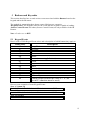
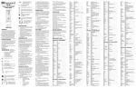
11 ASCII Character Set to HEX Conversion Chart
37
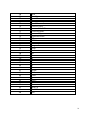
12 Russound Controllers RS-232 Hex Code Listing
38
39
40
41