1
HAL
Crestron Control Systems Guide
Halogen Software
Crestron Control Systems Guide Version 4
Crestron® is a registered trademark of Crestron Electronics, Inc.
Table of Contents
CHAPTER 1: Overview
1
About This Document
1
Using the HAL System Documentation
1
Getting Started
3
CHAPTER 2: Introduction to Using External Control Systems with HAL
4
Configuring External Controls in Halogen
4
Connecting to a Halogen/HAL Control Server
4
Communicating with a Halogen/HAL Control Server
5
Using a Telnet Client to Test and Monitor the System
5
CHAPTER 3: Example HAL1x Configuration
Creating the Example Configuration
Configuration Summary
CHAPTER 4: Integrating Crestron Control Systems with HAL
6
6
15
16
Overview
16
Checklist
17
Getting Started
17
Configuring IP Addresses
19
Ethernet Units
20
XPanel
22
Ethernet Communication Symbols
23
Signal Names
25
Toggles
26
Toggle Presets
29
Wall Toggles
32
Commands
Command Presets
Levels
Sliders
34
35
37
39
ii
CRESTRON CONTROL SYSTEMS GUIDE
Selectors
Source Selector
44
Preset Selector
46
Troubleshooting
APPENDIX A: HAL External Control Message Protocol
Details of external control messages
iii
40
47
49
49
All Controls
50
Level Controls
50
Toggle Controls
52
Selector Controls
54
Command Controls
57
Communications Monitoring
58
APPENDIX B: Using PuTTY to Test External Control Systems
59
APPENDIX C: Crestron Source Code
65
Trademarks
67
CHAPTER 1: Overview
About This Document
This guide explains how to use a HAL DSP Processor with Crestron control systems. It is divided into three major
sections:
l
"Introduction to Using External Control Systems with HAL" on page 4 (Chapter 2)
l
"Example HAL1x Configuration" on page 6 (Chapter 3)
l
"Integrating Crestron Control Systems with HAL" on page 16 (Chapter 4)
Chapter 2 explains the general approach for configuring a HAL for use with any external control system and how
to connect and communicate with the HAL Control Server. The second section, Chapter 3, walks you through the
construction of an example Halogen configuration that includes one or two common uses for each type of external
control. Chapter 4 shows you how to set up and program a Crestron control system to work with a HAL that is running the example configuration.
The appendices provide helpful reference information about the HAL external control message protocol and how
to use a telnet client to monitor and troubleshoot the operation of a control system at the message protocol level.
Using the HAL System Documentation
A variety of documentation is available to help you get started with and use your HAL System:
Halogen Help System
A comprehensive help system is installed with the Halogen software. It contains all the information you need
to work with the system. There are several ways to access the Help System:
l
Click the Help icon on the application toolbar:
Clicking the icon itself opens the Help System.
Clicking the down arrow displays a list of options including such things as access to the Rane website, checking for updates to the Halogen software, and sending an email to Rane.
l
Click the Help icon
that appears in the upper right corner of Halogen dialog boxes. Clicking this
icon opens the Help topic related to the specific dialog box. From there you can access the entire Help
System, if needed.
l
Right-click on different elements in the user interface. A Help option appears in the context menu.
Click this option to open the relevant Help topic. Pressing F1 when an area of the user interface has
focus also displays its relevant Help topic.
l
To search for information within the Help System, you can use the tabs on the Help Viewer's left pane
to search the index (click the Index tab) or perform a full-text search (click the Search tab). You can
also use the Quick search box in the Help System toolbar to search for text within the currently displayed topic:
HAL System Design Guide
This guide is offered as a PDF file and contains a product overview, details about the HAL System's key features, and best practices for designing a HAL audio system. Note that the information in this guide is also
available in the Halogen Help System. You can find this guide on the Rane website (http://rane.com/hal) as
1
CRESTRON CONTROL SYSTEMS GUIDE
well as on the product DVD.
HAL System Installation Guide
This guide is offered as a PDF file and includes step-by-step instructions on installing the HAL hardware,
loading a configuration, and testing the system. This information is also included in the Halogen Help System. You can find this guide on the Rane website (http://rane.com/hal) as well as on the product DVD.
AMX Control Systems Guide
This guide, includes an introduction to using external control systems with HAL. It also discusses an example HAL1 configuration and how to set up an AMX controller and touch panel to communicate with a Halogen/HAL Control Server. In addition, an appendix is included with reference information on the
HAL external control message protocol and how to use a telnet client to monitor and troubleshoot the operation of a control system at the message protocol level.
The guide is designed to be used in conjunction with the files found in the AMX Support Package. The contents of this support package include:
l
AMXControlSystems_Guide.pdf - The AMX Guide pdf file
l
ControlSystemSample.hal - Halogen configuration file intended for loading in Halogen or your
HAL1x
l
Rane_HAL.apw - NetLinx Studio program project file
l
Main.axs - NetLinx program source file
l
Rane_HAL_TP.TP4 - TPDesign4 touch panel project file
The AMX Support Package is installed with the Halogen software and can be accessed from the Windows
Start Menu under Rane Corporation -> Halogen -> Guides -> AMX. If you want to access the files directly
they are available on the product DVD or from the Halogen install directory:
l
Windows 8, 7 or Vista - C:\Program Files (x86)\Rane Corporation\Halogen\Guides\Support Packages\AMX directory
l
Windows XP - C:\Program Files\Rane Corporation\Halogen\Guides\Support Packages\AMX directory.
You can also download the most up-to-date version of this support package from the Rane website
(http://rane.com/hal).
Crestron Control Systems Guide
This guide, includes an introduction to using external control systems with HAL. It also discusses an example HAL1x configuration and how to set up a Crestron controller and virtual touch panel to communicate
with a Halogen/HAL Control Server. In addition, an appendix is included with reference information on the
HAL external control message protocol and how to use a telnet client to monitor and troubleshoot the operation of a control system at the message protocol level.
The guide is designed to be used in conjunction with the files found in the Crestron Support Package. The
contents of this support package include:
2
l
CrestronControlSystems_Guide.pdf - The Crestron Guide pdf file
l
ControlSystemSample.hal - Halogen configuration file intended for loading in Halogen or your
HAL1x
l
Rane_HAL.smw - SIMPL Windows program project file
l
Rane_HAL_TP.vtp - VisionTools Pro-e touch panel project file
CHAPTER 1: Overview
l
Rane HAL Level Processor.usp - SIMPL+ user module source file
l
Rane HAL Level Processor.ush - Compiled user module
The Crestron Support Package is installed with the Halogen software and can be accessed from the Windows
Start Menu under Rane Corporation -> Halogen -> Guides -> Crestron. If you want to access the files directly
they are available on the product DVD or from the Halogen install directory:
l
Windows 8, 7 or Vista - C:\Program Files (x86)\Rane Corporation\Halogen\Guides\Support Packages\Crestron directory
l
Windows XP - C:\Program Files\Rane Corporation\Halogen\Guides\Support Packages\Crestron directory.
You can also download the most up-to-date version of this support package from the Rane website
(http://rane.com/hal).
Stardraw Control Systems Guide
This guide, includes an introduction to using external control systems with HAL. It also discusses an example HAL1 configuration and an example Stardraw Control application and driver that communicates with a
Halogen/HAL Control Server. In addition, an appendix is included with reference information on the
HAL external control message protocol and how to use a telnet client to monitor and troubleshoot the operation of a control system at the message protocol level.
The guide is designed to be used in conjunction with the files found in the Stardraw Control Support Package. The contents of this support package include:
l
StardrawControlSystems_Guide.pdf - The Stardraw Control Guide pdf file
l
ControlSystemSample.hal - Halogen configuration file intended for loading in Halogen or your
HAL1x
l
HAL1 Stardraw Example Project.s03 - Stardraw Control Project
l
HAL1 Example Driver.cs - Stardraw HAL1 driver source code. This is part of the Stardraw Control
Project but is included separately here for reference.
The Stardraw Control Support Package is installed with the Halogen software and can be accessed from the
Windows Start Menu under Rane Corporation -> Halogen -> Guides -> Stardraw Control. If you want to
access the files directly they are available on the product DVD or from the Halogen install directory:
l
Windows 8, 7 or Vista - C:\Program Files (x86)\Rane Corporation\Halogen\Guides\Support Packages\Stardraw Control directory
l
Windows XP - C:\Program Files\Rane Corporation\Halogen\Guides\Support Packages\Stardraw Control directory.
You can also download the most up-to-date version of this support package from the Rane website
(http://rane.com/hal).
Getting Started
Read this document in sequence if you are completely new to learning about and using external control systems
with HAL and the Halogen software. Chapters 2 and 3 appear in other control systems guides so you can skip
these if you’ve already read them. The Crestron example in chapter 4 refers to the example HAL1 configuration
often, so you may want to familiarize yourself by reading chapter 3 before starting on chapter 4.
3
CHAPTER 2: Introduction to Using External
Control Systems with HAL
This section is a brief overview of the support that the HAL system provides for external controls and how your
system can connect to and use these controls. For more information on this topic, please see the Halogen Online
Help.
Configuring External Controls in Halogen
Halogen provides the ability to configure controls for use with external control systems. These controls can be of
any of the four types that Halogen supports: Level, Toggle, Selector, and Command. Once you create an external
control in Halogen using the Control Systems dialog, you can then link it to any other linkable control of the
same type in your Halogen configuration. This lets your external control system set and monitor any linkable
parameter in your HAL configuration. Since the external controls can link to any other linkable control in a configuration, you have tremendous flexibility in the access that you provide to end users and seamless integration of
your control system with internal controls, such as those in DSP block parameters and Rane Digital Remotes.
Each control that you configure for external access includes a unique number that allows external control systems
to identify each control. For example, you might define a level control to be number 1 while a toggle control is
number 2.
Connecting to a Halogen/HAL Control Server
The HAL system contains a Control Server to provide a way for your control system to connect and use the configured external controls. To integrate your external control system with a HAL system, your control system simply
connects to the Control Server over TCP/IP. In the spirit of allowing you to configure and test your HAL system as
much as possible without needing actual HAL hardware present, there are two ways that you can connect to a
HAL Control Server to develop, test and use your external control system.
First, when developing and testing your system, the Halogen software includes the Control Server, which runs
whenever Halogen is not connected to a HAL. Even though the configured HAL system hardware is not present,
using the Control Server built into Halogen allows you develop your configuration, including all of the external
controls, and test them with your external control system. Of course, because the actual hardware is not present,
you cannot process audio or use physical devices such as Digital Remotes.
To use the Control Server built into Halogen, connect to port 4996 on the TCP/IP address of the PC
that is running Halogen.
NOTE:
The other way to use the Control Server is to connect to a HAL DSP Processor itself. This server is always available on a HAL at port 4996 on any of its TCP/IP addresses. Once you have created and applied a HAL configuration that contains external controls, these controls are available to your external control system via the
Control Server. We recommend that you configure a static IP address on your HAL when using the HAL Control
Server, so that the server is always available to your control system at a stable address.
NOTE:
To use the Control Server built into HAL, connect to port 4996 on the TCP/IP address of the HAL.
4
CRESTRON CONTROL SYSTEMS GUIDE
Communicating with a Halogen/HAL Control Server
Once connected to either the Control Server built into Halogen or to the server in an actual HAL, your external
control system communicates with the Control Server using the HAL system External Control Message Protocol.
This is an ASCII text based protocol that allows one or more control systems to access the external controls in
your HAL configuration. Appendix A "HAL External Control Message Protocol" on page 49 fully defines these
messages, but an example would be: <L&4&510>. This message is a ‘set level’ message that tells the HAL to set
external level control number 4 to a new value of 51.0%. The protocol provides similar messages for getting and
setting values for each of the four control types.
In addition to responding to messages it receives, the Halogen/HAL Control Server also sends messages to connected control systems whenever one of the external controls configured in HAL changes. This helps all of the connected external control systems remain up to date as values or links change.
Using a Telnet Client to Test and Monitor the System
Because the message protocol is ASCII text, you can use a standard telnet client to connect to a Halogen or HAL
Control Server and send/receive messages. This can be a great way to initially test your control system and to troubleshoot any problems that occur while developing and deploying your system. Appendix B "Using PuTTY to
Test External Control Systems" on page 59 provides complete information for you to use a simple public domain
Windows telnet client, PuTTY, with the Halogen/HAL Control Server.
5
CHAPTER 3: Example HAL1x Configuration
The external control system example uses a HAL1x configuration that includes a set of external controls linked to
processing block and preset controls that demonstrate some common uses of the end user external controls. There is
at least one control of each type: Command, Level, Selector, and Toggle. We’ve also constructed this configuration
using only inputs and outputs available on the HAL1x so that you can load and apply this configuration to any
HAL1x without having to attach and configure other devices such as RADs or DRs.
"Creating the Example Configuration" below shows how to build the complete configuration from scratch. Of
course, we also provide the configuration file for you so you don’t have to go through all of the work, but it’s
your choice. You can either follow the directions below to create the configuration or open the file we provide
and use the instructions below to learn about what’s in the configuration.
Alternatively, you can just read the "Configuration Summary" on page 15 to learn what external controls this configuration provides.
Creating the Example Configuration
To get started, all of the work is done in the processing workspace, so click on the Processing tab in the upper
right section of the Halogen application.
Click on the tab for the I/O palette and drag the first five HAL1x Mic/Line inputs from the palette and drop them
on the left side of the processing map. In a similar way, drag the first three HAL1x Line Outputs from the palette
and drop them on the right side of the processing map.
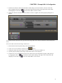
Next, fill in the middle processing area by clicking on the DSP palette tab and dragging four processing blocks to
the processing map: Parametric EQ, Distributed Program Bus, Room Combine, and Selector. For the selector block,
create one additional input and set the input names to Classical, Jazz, and Reggae. Also, delete room C from the
Room Combine Processor by clicking the red ‘X’ in room C. Wire these together with your I/O blocks so that your
processing map looks like this:
6
CRESTRON CONTROL SYSTEMS GUIDE
The top row of blocks provides audio for a lounge that has three program source inputs and some PEQ processing
and the bottom row is a simple room combine configuration.
Next, we’ll add some external controls using the External Control Systems dialog and link them to some of the
controls available in the processing blocks we are using.
First, we’ll create a control for the lounge input program selector:
1. Just above the upper left of the Processing Workspace, click on the Control Systems button then select
External Controls to open the External Control Systems property dialog.
2. In the External Control Systems dialog, click on the Select tab.
3. Create a new Selector control by clicking on the
button.
4. Change the name of this new control by clicking the edit icon
and entering Source Selector Control
followed by the Enter key.
5. Set its number to 1.
6. Double click the Selector block in the Processing Map to open its property dialog
7
CHAPTER 3: Example HAL1x Configuration
7. Link the new Selector control in the External Control dialog to the selector block’s selector control. Do
this by dragging the link icon
in the External Control Systems dialog to the right of the control name
and dropping it on the link icon
for the Selector Block’s selector control.
8. Change the Label in the Source Selector Control to "Source". Together, the selector property dialogs are as
follows:
Your external control system can now get and set the lounge input source using the External Control Message Protocol.
Next, we’ll add a control for the lounge volume level:
1. In the External Control Systems dialog, click on the Level tab.
2. Create a new Level control by clicking on the
button.
3. Change the name of this new control to Lounge Level Control and set its number to 6.
4. Open the property dialog for the lounge output block, HAL1x Line Output (1).
5. Link the new Level external control to the level control in the Line Output block property dialog. Do this
by dragging the link icon
in the External Control Systems dialog to the right of the control name and
dropping it on the link icon
for the Line Output Block’s level control.
8
CRESTRON CONTROL SYSTEMS GUIDE
6. Change the Label for the Lounge Level Control "Lounge Volume". The dialogs appear below as follows:
In a Room Combine application, end users typically need to let the audio system know when they open or close a
movable wall. To create a Toggle control for this:
1. Open the Room Combine Processor property dialog.
2. Drag both Room A and Room B onto the Layout & Control area and arrange them so that they are next
to each other.
3. Add a movable wall between them by dragging the movable wall icon between the rooms until the wall
highlights, then dropping the wall to create a wall toggle control.
4. In the External Control Systems dialog, click on the Toggle tab.
5. Add a new Toggle control by clicking on the
button.
6. Change the name of the new control to Wall Toggle Control and set its number to 5.
7. Link the new Toggle external control to the wall toggle control in the Room Layout & Control area. Do
this by dragging the link icon
in the External Control Systems dialog to the right of the control name
and dropping it on the link icon
for the wall toggle control between the two rooms.
9
CHAPTER 3: Example HAL1x Configuration
8. Change the Label for the Wall Toggle Control to "Wall Toggle". The dialogs appear below as follows:
At this point, your external control system has access to three controls – a selector to get and set the lounge input
program source, a level to control the lounge volume and a toggle to open and close the room combine wall.
Now we’ll add some controls and link them to presets of various kinds to show how you can provide access to presets to your external control system.
First, we’ll add a toggle control to mute all of the outputs in our configuration:
1. On the Processing Workspace Toolbar, click on the Presets button to open the All Presets property
dialog.
2. In the All Presets dialog, click on the Toggle tab.
3. Add a new toggle preset by clicking on the +Preset button.
4. Rename this preset to Mute All Preset.
5. In the External Control Systems dialog, click on the Toggle tab if it is not already displaying the toggle
controls.
6. Add a new Toggle external control by clicking on the
7. Rename this new control to Mute All Toggle Control.
button and set its number to 4.
10
CRESTRON CONTROL SYSTEMS GUIDE
8. Link the new Mute All Toggle Control to the toggle control for the Mute All Preset. Do this by dragging
the link icon
in the External Control Systems dialog to the right of the control name and dropping it
on the link icon
for the Mute All Preset’s toggle control.
9. Change the Label for the Mute All Toggle Control to "Mute All". The dialogs appear below as follows:
10. Open the three HAL1x output blocks, set each of the mute checkboxes to checked (muted) and set their
level controls all the way down (Off).
11. Add the three HAL1x output blocks to the Mute All Preset. To do this, hover your mouse over the
HAL1x output block for the lounge. Drag the blue preset icon
that appears and drop it on the blue
rectangle for the Mute All Preset in the All Presets dialog. Repeat for the other two HAL1x output blocks.
11
CHAPTER 3: Example HAL1x Configuration
12. Test this by activating and deactivating the Mute All Preset from the All Presets dialog. All three HAL1x
output blocks mute when the preset is active and un-mute when the preset is not active.
Now, we’ll add a Command control to reset all outputs to a default operating state:
1. In the All Presets dialog, click on the Command tab.
2. Create a new command preset by clicking on the +Preset button.
3. Rename this new preset to Default Level Preset.
4. In the External Control Systems dialog, change to the Toggle tab if it is not already selected.
5. Make sure the Mute All Toggle Control toggle Value is un-checked.
6. Open the three HAL1x output blocks and set the level for each to -20.0 dB and un-check the mute toggle
control.
7. Add the three HAL1x output blocks to the new Default Level Preset by dragging the blue preset icon
next to each HAL1x output block and dropping them on the blue rectangle for the Default Level Preset in
the All Presets dialog.
8. In the External Control Systems dialog, drag the blue preset icon for the Mute All Toggle Control and
drop it on the blue rectangle for the Default Level Preset in the All Presets dialog. This ensures that the
Mute All toggle is reset (unmuted) when the Default Level Preset is asserted.
9. In the External Control Systems dialog click on the Command tab.
10. Add a new Command external control by clicking on the
button.
11. Rename this new control to Default Command Control and set its number to 3.
12. Link the Default command control to the Default Level Preset’s Assert button. Do this by dragging the
link icon
in the External Control Systems dialog to the right of the control name and dropping it on
the link icon
for the Default Level Preset’s Assert button.
12
CRESTRON CONTROL SYSTEMS GUIDE
13. Change the Default Command Control's Label to "Default Level". The dialogs appear below as follows:
Finally, we’ll create a selector preset to provide three options for the PEQ settings in the lounge
1. In the All Presets dialog, click on the Selector tab.
2. Create a new Selector preset by clicking on the +Selector button.
3. Rename this selector preset to PEQ Preset Selector.
4. Add three presets to this selector by clicking the +Preset button three times.
5. Change the names of these presets to Soften Vocals, Smooth, and Boost Bass.
6. Activate the Soften Vocals preset by clicking on the radio button to the left of its name in the All Presets
dialog. Then uncheck the Include 'No Selector' checkbox at the bottom of the PEQ Selector Preset.
7. Open the property dialog for the PEQ block and set the Gain to -15.0 and the Frequency to 3276.
8. Add the PEQ block to the Soften Vocals preset – that is the first preset in the selector preset. To do this,
drag the blue Preset icon next to the PEQ block in the processing map and drop it on the blue ‘<Add>’
rectangle for the Soften Vocals preset.
9. Set the PEQ frequency to 1589 and add the PEQ block to the Smooth preset.
10. Set the PEQ frequency to 393, the Gain to +12.0 and add the PEQ block to the Boost Bass preset.
11. Test the preset selector by clicking on the Active radio buttons and observing the PEQ change.
12. In the External Control Systems dialog click on the Select tab.
13. Create a new Selector external control by clicking on the
button.
14. Rename this new control to PEQ Selector Control and set its number to 2.
13
CHAPTER 3: Example HAL1x Configuration
15. Link the PEQ Selector Control to the PEQ Preset Selector control in the All Presets dialog. Do this by
dragging the link icon
in the External Control Systems dialog to the right of the control name and
dropping it on the link icon
for the PEQ Preset Selector control.
16. Change the PEQ Selector Control's Label to "Tone". The dialogs appear below as follows:
Wow, that’s the whole configuration. Be sure to save your configuration before quitting Halogen.
14
CRESTRON CONTROL SYSTEMS GUIDE
Configuration Summary
The example configuration provides the following external controls:
1. A Selector for lounge program source – control number 1
There are three selections: Classical, Jazz, and Reggae
2. A Selector for lounge tone (PEQ) – control number 2
There are three selections: Soften Vocals, Smooth, and Boost Bass.
3. A Level for lounge volume – control number 6
This changes the output block’s level for the lounge.
4. A Toggle to mute all audio outputs – control number 4
This mutes all output blocks and sets their levels to Off. While setting the levels is not necessary, we’ve
included it here to cause the lounge output level to change so the Halogen/HAL Control Server will send
a ‘set level’ message.
5. A Toggle to open and close the wall of a room combine block – control number 5
6. A Command to reset audio outputs to default levels – control number 3
This sets the three outputs to -20.0dB and un-mutes them. In addition, it sets the Mute All toggle control
to unchecked so the state is consistent with the outputs being un-muted.
15
CHAPTER 4: Integrating Crestron
Control Systems with HAL
Overview
This guide describes how to setup a Crestron controller and virtual touch panel to communicate with a Halogen/HAL Control Server. It is designed to be used in conjunction with the files found in the Crestron Support
Package. The contents of this support package include:
l
CrestronControlSystems_Guide.pdf - The guide you are reading now
l
ControlSystemSample.hal - Halogen configuration file intended for loading in Halogen or your HAL1x
l
Rane_HAL.smw - SIMPL Windows program project file
l
Rane_HAL_TP.vtp - VisionTools Pro-e touch panel project file
l
Rane HAL Level Processor.usp - SIMPL+ user module source file
l
Rane HAL Level Processor.ush - Compiled user module
The Crestron Support Package is installed with the Halogen software and can be accessed from the Windows Start
Menu under Rane Corporation -> Halogen -> Guides -> Crestron. If you want to access the files directly they are
available on the product DVD or from the Halogen install directory:
l
Windows 7 or Vista - C:\Program Files (x86)\Rane Corporation\Halogen\Guides\Support Packages\Crestron
directory
l
Windows XP - C:\Program Files\Rane Corporation\Halogen\Guides\Support Packages\Crestron directory.
You can also download the most up-to-date version of this support package from the Rane website
(http://rane.com/hal).
You do not need to connect your controller to an actual HAL in order to test your control system. A
PC running Halogen can simulate all the feedback your controller would get from a HAL running the same
configuration.
NOTE:
This guide walks you through the configuration of a Crestron TCP/IP client, e-Control and XPanel. It then
describes how to wire logic symbols for serial communications with a Halogen/HAL Control Server using a Serial
Buffer and Serial I/O. After explaining our general communications strategy, we then turn our attention to the
HAL’s specific control types.
The HAL system has four types of controls: toggles, commands, levels and selectors. All four are accessible to
external TCP/IP clients like a Crestron controller. This guide covers each of these control types in depth one-byone. First we dive into the logic symbols and signal flow for the control type. Then we use the control type in
some touch panel applications. The applications are:
l
Toggle button to activate and deactivate a preset.
l
Toggle button to open and close a wall in a room combine block.
l
Command button to assert a preset.
l
Slider to adjust the level on an output.
16
CHAPTER 4: Integrating Crestron Control Systems with HAL
l
Radio buttons to select between input sources.
l
Radio buttons to select between presets.
The guide concludes with a troubleshooting section that covers the most common problems encountered when configuring a target system for the examples.
Checklist
To use the files from the Crestron Support Package and follow along with the examples you will need:
l
A Windows desktop or laptop with an Ethernet port and the latest Rane Halogen (1.1.0 or higher) and Crestron SIMPL Windows and Vision Tools Pro-e software installed.
l
A Crestron controller with Ethernet. The example project is configured for an MC2E but you can replace
this with another Crestron Ethernet controller.
l
An Ethernet switch and cables for the PC and controller.
Although you will ultimately connect a HAL to your control system all of the integration and testing can be
accomplished without a HAL.
This guide assumes that the reader has had some exposure to Crestron programming and is able to navigate the
Crestron software. A typical workflow for developing a Crestron application is:
• Configure your Crestron controller, touch panel[s] and TCP/IP connections to other devices in the SIMPL Windows Configuration Manager.
• Add logic symbols to the SIMPL Windows Program View and name their signals so that the routing results in
the desired program.
• Compile the program and transfer it to your controller.
• Draw a custom touch panel user interface in Vision Tool Pro-e.
• Join button and slider numbers in the user interface with digital and analog inputs and outputs in the program.
• Compile the user interface and transfer it to your touch panel[s].
Once your application is running you can use the SIMPL debugger in Crestron Toolbox to pinpoint mistakes in
your program by watching how signal states change as you interact with your touch panel[s].
Getting Started
This section shows how to set up your system so that you can get the most out of the examples. The principal components of your system are the Windows PC and Crestron controller. Both should reside on the same network so
that they can communicate easily. Configure their IP settings and plug them into the Ethernet switch using the Ethernet cables.
Launch Halogen on the PC so that it can pretend to be a HAL. A virtual HAL starts running on your PC when
you launch Halogen. This process goes away when you exit Halogen. Make sure to have the right configuration
file open in Halogen when testing your system. Use the ControlSystemSample.hal file that came with the Crestron
Support Package when working with the examples.
17
CRESTRON CONTROL SYSTEMS GUIDE
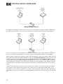
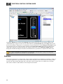
Minimal Example Network
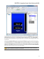
In addition to substituting for a HAL, the PC will also act as a touch panel by using the standalone XPanel desktop application generated by Vision Tools Pro-e. The XPanel executable should be targeted for Windows PCs.
Later on you can choose to run the XPanel on a different PC to simulate a more realistic installation environment.
For now, run Halogen and the XPanel on the same PC as shown in the Minimal Example Network diagram.
Run the example program on the controller so that it can talk to Halogen Control Server and the XPanel. Open the
Rane_HAL.smw program file in SIMPL Windows. Switch to the Configuration Manager. If your controller is not
an MC2E, right-click on the MC2E node in the lower System Views pane and select Replace “MC2E” from the
context menu to bring up the Select New Device dialog. Select the model of your controller from that dialog and
click the OK button. Change the server address of the TCP/IP client and the IP address of the XPanel so that they
both match your PC’s IP address. Compile the program and transfer the resulting Rane_HAL.spz file to your controller.
Compile and run the XPanel on the PC so that it can talk to the controller. User interface widgets on the XPanel
are assigned to specific outputs in the program so the two depend on each other. Open the Rane_HAL_TP.vtp
project file in Vision Tools Pro-e and hit F12 to compile it. This will generate a Rane_HAL_TP.exe folder in the
same directory as the project. Double-click the LaunchXPanel.exe file located in this new directory to run the XPanel.
18
CHAPTER 4: Integrating Crestron Control Systems with HAL
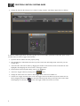
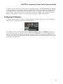
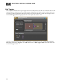
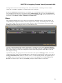
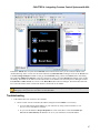
You know all of the components of your system are communicating properly when the Connected status indicator
in the upper right corner of the XPanel is blue. If the XPanel fails to connect to the controller on startup, an error
pop-up dialog saying “Control System Connection: Disconnected” will eventually appear. If this dialog does not
come up but the connected status indicator is still blacked out then the controller is not connecting to Halogen.
Refer to "Troubleshooting" on page 47 if you find yourself struggling to establish communications.
Configuring IP Addresses
A Crestron controller connects to a HAL or PC running Halogen via TCP/IP. The easiest way to accomplish this
connectivity is by assigning the HAL or PC a static IP address.
You configure a HAL’s static IP addresses from the Host Device Settings dialog in the Hardware workspace. To
access this dialog, connect to your HAL, hover your mouse over the HAL bar at the top of the Hardware Map,
then click on the gear icon that appears. The Host Device Settings dialog is only available when Halogen is connected to a HAL. Host Device Settings like static IP assignments reside solely on that HAL and do not travel with
the Halogen configuration file.
19
CRESTRON CONTROL SYSTEMS GUIDE
PCs are frequently setup to use dynamic IPs but a static IP is preferable if you want to use your PC in place of a
HAL during development. The controller tries to connect to a TCP server (your PC in this case) at a specific IP
address. If your PC has a dynamic IP address assigned to it that address may change if it is disconnected from the
network or the DHCP lease expires. You also probably do not want to configure your PC with the same static IP
as your HAL in the event that both are connected to the same network.
Control system networks are typically private networks with no direct route to the Internet except through a gateway or proxy server. Certain IP address ranges are reserved for private networks. 10.0.0.0 to 10.255.255.255 is one
of those address ranges. Start with a small self-contained network. Plug your Halogen PC, controller, XPanel PC
and HAL into the same Ethernet switch and assign each one a unique static IP in the 10.0.0.0 network.
Ethernet Units
This section shows you how to set up the Ethernet Units in the Crestron system configuration so that the examples
work.
20
CHAPTER 4: Integrating Crestron Control Systems with HAL
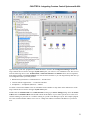
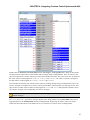
Open the Rane_HAL.smw program file in SIMPL Windows. Switch to the Configuration Manager. Below the
large controller device block in the upper System Views pane you will see a row of Ethernet Units. The row contains the following device icons: TCP/IP Client, e-control PC Interface and XPanel. These devices originated
from different folders in the Device Library tree. Here are their locations so you can drag and drop them into system configurations that you build yourself.
l
Ethernet Intersystems/Device Communication -> TCP/IP Client
l
Crestron Software Applications -> e-Control PC Interface
l
Touchpanels -> Touchpanels (Ethernet) -> XPanel
To add an e-Control and XPanel to the list of Ethernet Units remember to drop them on the Ethernet slot of the
large controller device block in the upper System Views pane.
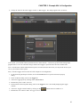
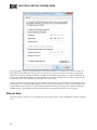
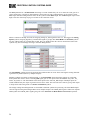
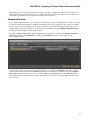
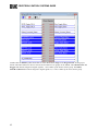
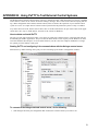
Double-click the TCP/IP Client icon in Ethernet Units to bring up its Device Settings dialog. Select the IP Net
Address tab. The Default Address field should contain the IP address of your control systems server. This server
could be running on your HAL or it could be running on your PC when Halogen is open. The example program
file comes with the Default Address set to 10.0.0.6. Change this address to match the IP address of your PC for
now.
21
CRESTRON CONTROL SYSTEMS GUIDE
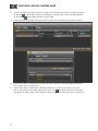
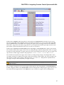
Double-click on the e-Control PC Interface icon in Ethernet Units to bring up its Device Settings dialog. Select
the IP Net Address tab. The Default Address field should be set to 127.0.0.1. This is the loopback address of any
PC so there should be no reason to ever change it. An e-control is what enables a PC to act like an Ethernet touch
panel. Remember the e-control’s IP ID of 4. You will need it for the XPanel Project Properties dialog in Vision
Tools Pro-e.
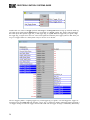
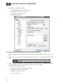
Double-click the XPanel icon in Ethernet Units to bring up its Device Settings dialog. Select the IP Net Address
tab. The Default Address field should contain the IP address of the PC where the XPanel is going to be executed.
The example program comes with the Default Address set to 10.0.0.6. Change this address to match the IP address
of your PC. For now, this should be the same PC running Halogen. You can change it again later if you decide
you want to try running the XPanel from a different PC.
XPanel
This section shows you how to set up the XPanel executable’s communication settings so that the examples work.
Have the IP address of your controller and the IP ID of the e-control handy before proceeding.
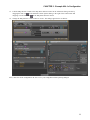
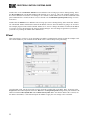
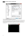
Open the Rane_HAL_TP.vtp project file in Vision Tools Pro-e. Right-click on the Rane_HAL_TP project in the
Project View and select Properties. Select the Web tab in the Project Properties dialog. Enter your controller’s IP
address for both Control System Info and e-control Gateway Info. Make sure that the IP ID of the e-control, not
the IP ID of the XPanel, is selected. Recompile the XPanel to apply the new settings to the executable.
22
CHAPTER 4: Integrating Crestron Control Systems with HAL
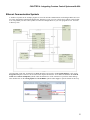
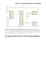
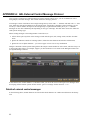
Ethernet Communication Symbols
A number of symbols in the example program are wired for TCP/IP communications with Halogen/HAL and e-control. Trace through the TCP/IP Serial Signal Flow diagram to get an overview of how these symbols work together.
You will probably use these same symbols to connect to Halogen/HALs in your own programs so now let’s look
at them up close.
Open the Rane_HAL.smw program file in SIMPL Windows and switch to the Program Manager. Click on the
Program View pane so that it is in focus and select Expand All from the View menu. Double-click the TCP/IP
Client and e-control Touchpanel symbols under the Ethernet slot of the controller to open their details dialogs.
Then double-click on the Analog Equate and Serial Buffer symbols under Logic to open the details for those up.
23
CRESTRON CONTROL SYSTEMS GUIDE
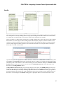
The Port parameter for a TCP/IP Client connecting to a HAL should always be set to 4996. The same goes for a
client connecting to a PC that is impersonating a HAL. Data gets sent to Halogen/HAL via the symbol’s serial
TX$ input. Data from Halogen/HAL comes out the symbol’s serial RX$ output. The Connect digital input is held
high so that the client keeps trying to reconnect if the connection is lost.
When a connection attempt succeeds, the outgoing analog IP_STAT signal becomes a 2. This triggers the Analog
Equate symbol’s outgoing digital IP_CONNECTED signal to go high. The Serial Buffer and Serial/IO symbols
are only enabled when IP_CONNECTED is high. They are disabled when the client is disconnected since both
symbols only deal with strings traveling to and from Halogen/HAL.
The Serial Buffer symbol protects the program from problems that can occur when serial signals coming from Halogen/HAL are jammed (driven by multiple outputs).
Multiple symbols send strings to Halogen/HAL, so the Serial Buffer keeps them from stepping on each other.
Each symbol that wants to write to the TO_DSP signal gets its own input on the Serial Buffer: TO_DSP1, TO_
DSP2, TO_DSP3, etc. The Serial Buffer routes these inputs to the same TO_DSP output. If multiple inputs are
issued simultaneously the output is generated in successive order. The end result is the same as giving each output
a unique name and routing them to a Serial Concatenation symbol.
The strings coming from Halogen/HAL are forwarded to different symbols for processing. The Serial Buffer duplicates the signal coming from Halogen/HAL across multiple outputs. The FROM_DSP signal is forked into separate
FROM_DSP1 and FROM_DSP2 signals going out to the Serial I/O and Rane HAL Level Processor symbols.
24
CHAPTER 4: Integrating Crestron Control Systems with HAL
The e-control PC interface enables an XPanel to connect to the LAN that its PC host is on. The e-control Touchpanel symbol looks just like an Ethernet Touchpanel symbol in terms of ins and outs. All of the signals that are
on the XPanel symbol should be applied to the same inputs and outputs on the e-control Touchpanel. This allows
signals to flow out from the XPanel through the e-control over the LAN to the controller and vice versa.
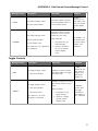
Signal Names
A few signal naming conventions are used throughout the example program. It helps to familiarize yourself with
them before delving further into the logic and signal flow of the program.
A button press signal from a touch panel output has the _Button suffix at the end of its name. A button feedback
signal to a touch panel input has the _fb suffix at the end of its name. Take the Wall Open button that appears on
the XPanel for example. The signal from its press2 output is named Wall_Toggle_Button and the signal to its fb2
input is named Wall_Toggle_ON_fb.
The _ON and _Off substrings appear in the names of some of the digital signals used for toggles. A toggle button
press could be turning a toggle on or off depending on its previous state. A press signal is transient so other signals are needed to capture and maintain the toggle’s state. When a signal with an _ON suffix goes high that
always indicates a toggle ON event. When a signal with an _Off suffix goes high that always indicates a toggle
Off event.
Several touch panel button press signals have a _Radio_Button suffix at the end of their name. The suffix is
intended for radio buttons that operate together as members of a group. Take the Source selector group of radio buttons on the XPanel for example. If the Classical radio button is selected then the Jazz and Reggae radio buttons
must be deselected. Because they are so closely related the signals for radio buttons belonging to the same group
are arranged close to one another throughout the program.
A _sel substring is used in digital signal names to indicate that signal is part of a selector. It takes the place of the
Radio_Button suffix in selector signals that aren’t driven by the touch panel. Take the Source selector as an example. The Serial I/O has outgoing CLASSICAL_sel, JAZZ_sel and REGGAE_sel signals for the three different source
selector positions that can come from Halogen/HAL. The _sel substring also appears in the names of certain toggle
25
CRESTRON CONTROL SYSTEMS GUIDE
signals. In that context the toggle is viewed as a 2-way selector with a toggle ON selection and a toggle Off selection.
Toggles
This section explains how to integrate HAL toggle controls with buttons on an XPanel by examining a couple of
touch panel applications: a preset toggle button and a wall toggle button. We start by breaking down the logic
symbols and signal flow for the HAL toggle controls. Then we examine how to bind the HAL toggle controls to
toggle buttons in the touch panel user interface.
Toggles in a HAL system have only an on or off state. They are represented as checkboxes in the Halogen software and DR remotes. Because toggles only have two states, they are modeled as digital signals in SIMPL. The
example program has symbols to deal with toggle button presses on a touch panel and toggle messages from a Halogen/HAL. Trace through the Toggle Control Signal Flow diagram to get an overview of how these symbols work
together before we look at them up close.
Open the Rane_HAL.smw program file in SIMPL Windows. There are two HAL toggle controls in this program
uniquely identified by HAL control numbers 4 and 5. These HAL control numbers appear in the Toggle tab of Halogen’s External Control Systems dialog as Mute Toggle Control and Wall Toggle Control.
26
CHAPTER 4: Integrating Crestron Control Systems with HAL
Double-click the XPanel symbol under Slot-05 of the MC2E in the Program View. The Mute Toggle Control
maps to the digital fb1 input and press1 output on the XPanel. The Wall Toggle Control maps to the digital fb2
input and press2 output on the XPanel. The outgoing press signals for the two toggle buttons on the XPanel are
named Mute_Toggle_Button and Wall_Toggle_Button. A press signal from an XPanel goes high when that touch
panel button is pressed and falls back down to low as soon as it is released.
Double-click the Serial I/O and Serial Send symbols under Logic in the Program View to bring up their details.
The controller modifies HAL toggle control values by sending message strings to Halogen/HAL. These ‘set toggle’
messages are strings comprised of a toggle control type, HAL control number and value. The valid ‘set toggle’ messages for the two HAL toggle controls in this program are <T&4&0>, <T&4&1>, <T&5&0> and <T&5&1>.
The controller also requests HAL toggle control values by sending message strings to the Halogen/HAL. These
‘get toggle’ messages are comprised of a toggle control type and HAL control number. The valid ‘get toggle’ messages for the two HAL toggle controls in this program are <T&4> and <T&5>. Halogen/HAL responds to these
‘get toggle’ messages with corresponding ‘set toggle’ messages.
Refer to Appendix A "HAL External Control Message Protocol" on page 49 for more information on
toggle messages.
NOTE:
The ‘get toggle’ messages for the two HAL toggle controls appear in the string parameter of the Serial Send symbol that is triggered whenever the TCP/IP Client connects to Halogen/HAL. Requesting the toggle values on connect ensures that the toggle buttons on the XPanel are in sync with the live toggle values on Halogen/HAL.
27
CRESTRON CONTROL SYSTEMS GUIDE
Double-click one of the two Toggle symbols under Logic in the Program View to bring up its details. Each toggle button press signal from the XPanel drives a clock input on a Toggle symbol. The Toggle symbol translates
the button press into separate toggle ON_sel and toggle Off_sel signals. When the toggle ON_sel signal is high
the toggle Off_sel signal is low and vice versa. These signals are latched by the Toggle symbol so that when you
let go of a toggle button on a touch panel it stays in its new on or off state.
The two Toggle symbols -- outgoing toggle ON_sel and toggle Off_sel signals -- are what trigger the ‘toggle set’
messages sent by the Serial I/O. Take the Mute_Toggle_Off_sel signal, for instance. When that signal goes high, a
‘set toggle’ message to turn HAL toggle control 4 off is sent. The ‘set toggle’ message is immediately followed by
28
CHAPTER 4: Integrating Crestron Control Systems with HAL
a ‘get toggle’ message for the same HAL toggle control. Remember to include a ‘get toggle’ message with any 'set
toggle' message because Halogen/HAL does not echo a ‘set toggle’ message back to the client that sent it. This is
needed because the visible state of a touch panel toggle button is determined by its feedback signal and feedback
is only generated from incoming 'set toggle' messages.
Signals coming out of the Serial I/O go high when matching message strings are received from Halogen/HAL.
Take the Mute_Toggle_Off signal, for example. This signal goes high when a ‘set toggle’ message string of
<T&4&0> is received. The signal won’t go low again until another character is received and a match with the rightmost characters of the input string no longer exists. The same technique applies to the Mute_Toggle_On signal
when a ‘set toggle’ message string of <T&4&1> is received.
Double-click one of the two Set/Reset Latch symbols under Logic in the Program View to bring up its details.
Notice that Toggle_ON and Toggle_Off signals from the Serial I/O drive the set and reset inputs. The Set/Reset
Latch merges the two inputs into a single Toggle_ON_fb signal. This outgoing feedback signal is latched so that
when a toggle value change is received the toggle button stays in its new on or off state.
The feedback signals from the Set/Reset latches drive the fb1 and fb2 feedback inputs for the two toggle buttons
on the XPanel. These feedback signals are generated by the ‘set toggle’ message the Serial I/O receives from Halogen/HAL. These ‘set toggle’ messages are the same strings sent by the Serial I/O when toggle buttons are pressed
on the XPanel. They may arrive unsolicited or in response to a 'get toggle' message.
Refer to Appendix A "HAL External Control Message Protocol" on page 49 for more information on
toggle messages.
NOTE:
Toggle Presets
This example demonstrates how to get a toggle button on a touch panel to activate and deactivate a Halogen/HAL
preset. The example Halogen configuration file contains a toggle preset for muting and unmuting all the outputs
on a HAL. This Mute All Preset is linked to a Control Systems toggle control named Mute All Toggle Control.
Toggling this HAL control activates or deactivates the preset.
29
CRESTRON CONTROL SYSTEMS GUIDE
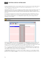
Open the ControlSystemSample.hal example configuration file in Halogen. Then open the External Control Systems dialog and select the Toggle tab. The Value checkbox for the Mute All Toggle Control reflects the current
state of that HAL toggle control.
30
CHAPTER 4: Integrating Crestron Control Systems with HAL
Open the Rane_HAL_TP.vtp project file in Vision Tools Pro-e. Next, open the Sound page window to view the
example touch panel design. Select the Mute All button in the Sound page window. Notice that the Digital Press
Join number for the Mute All button is set to 1 to match the fb1 input and press1 output on the XPanel symbol in
the program. The button will appear raised when it is in its inactive state and depressed when it is in its active
state.
Launch the XPanel and verify that the Connected status indicator shows you are connected. Refer to the "Troubleshooting" on page 47 section if it the status indicator says Disconnected. Click the Mute All button on the XPanel on and off. The touch panel button will remain in its new active or inactive state after you release the mouse
button. This is the latching behavior alluded to earlier. Now watch the Active state of the Mute All Preset in Halogen as you click the Mute All button on the XPanel. Lastly toggle the Mute All Preset from Halogen to see that
the Mute All button and Lounge slider on the XPanel respond.
Refer to Appendix B "Using PuTTY to Test External Control Systems" on page 59 for help with
debugging if the system does not behave as described here.
NOTE:
31
CRESTRON CONTROL SYSTEMS GUIDE
Wall Toggles
This example demonstrates how to get a toggle button on a touch panel to open and close a movable wall in a Halogen/HAL Room Combine block. The example Halogen configuration file contains a Room Combine block with
two rooms A and B. The movable wall in between these two rooms is linked to a Control Systems toggle control
named Wall Toggle Control. Toggling this HAL control opens and closes the wall.
Open the ControlSystemSample.hal example configuration file in Halogen, then open the External Control Systems dialog and select the Toggle tab. The Value checkbox for the Wall Toggle Control reflects the current state
of that HAL toggle control.
32
CHAPTER 4: Integrating Crestron Control Systems with HAL
Open the Rane_HAL_TP.vtp project file in Vision Tools Pro-e. Next, open the Sound page window to view the
example touch panel design. Select the Wall Open button in the Sound page window. Notice that the Digital
Press Join number for this button is set to 2 to match the fb2 input and press2 output on the XPanel symbol in
the program. The touch panel button will appear raised when it is in its inactive state and depressed when it is in
its active state.
Double-click the Room Combine (1) block in the Halogen Processing map to open its properties dialog. Select
the Layout and Control tab in the Room Combine (1) dialog. Launch the XPanel and verify that the Connected
status indicator shows that you are connected. Refer to the "Troubleshooting" on page 47 section if it the status
indicator says Disconnected. Watch the wall between rooms A and B appear and disappear as you click the Wall
Open button on the XPanel open and closed. Now toggle the wall open and closed from the Room Combine (1)
dialog and watch that same button turn on and off on the XPanel.
Refer to Appendix B "Using PuTTY to Test External Control Systems" on page 59 for help with
debugging if the system does not behave as described here.
NOTE:
33
CRESTRON CONTROL SYSTEMS GUIDE
Commands
This section explains how to integrate a HAL command control with buttons on an XPanel by examining a single
application: a touch panel button that asserts a HAL preset. We start by breaking down the logic symbols and signal flow for the HAL command control. Then we examine how to bind the HAL command control to a button in
the touch panel user interface.
Command controls are stateless in a HAL system. Unlike toggles, they have no on or off values. HAL Command
controls are merely triggers for predefined actions like command presets. Think of them as "Fire and forget."
Because they are stateless, the feedback for a command button on a touch panel must be momentary. The example
program has symbols to deal with command button presses from a touch panel. Let’s take a look at them.
Open the Rane_HAL.smw program file in SIMPL Windows. Double-click the XPanel symbol under the Ethernet
slot of the controller and the Serial I/O symbol under Logic in the Program View to bring up their details.
There is one HAL command control in this program uniquely identified by HAL control number 3. This control
number appears in the Command tab of Halogen’s External Control Systems dialog as Default Command Control.
Whenever the Default Level button on the XPanel is clicked the Serial I/O sends a message string to Halogen/HAL. These ‘command’ messages contain a command control type and a HAL control number. The only
valid ‘command’ message for the HAL command control in this example is <C&3>.
Refer to Appendix A "HAL External Control Message Protocol" on page 49 for more information on
command messages.
NOTE:
When a client sends a ‘command’ message, Halogen/HAL echoes it back to all its other clients. The Serial I/O in
this program currently ignores unsolicited <C&3> ‘command’ messages but you can add a string parameter to parse
them if you want your touch panel to exhibit feedback when they arrive.
34
CHAPTER 4: Integrating Crestron Control Systems with HAL
The momentary nature of a HAL command control makes generating feedback for a button on a touch panel very
simple. Just route the touch panel button’s press output signal to the feedback input signal. That’s all there is to it.
The button on the XPanel will only appear active when you hold it down.
Command Presets
This example demonstrates how to get a button on a touch panel to trigger a command preset on a HAL. The example Halogen configuration contains a command preset that sets the levels of all the HAL line outputs to a default
level of -40.0 dB. A preset like this is handy when a user wants to revert undesired audio settings back to their
original defaults. The preset is linked to a Control Systems command control named Default Command Control.
Invoking the HAL command control asserts the preset.
Open the ControlSystemSample.hal example configuration file in Halogen. Then open the External Control Systems dialog and select the Command tab. Clicking on the Default Level button in this dialog fires the
HAL command control.
Open the Rane_HAL_TP.vtp project file in Vision Tools Pro-e. Next open the Sound page window to view the
example touch panel design. Select the Default Level button in the Sound page window. Notice that the Digital
Press Join number for this button is set to 4 to match the fb4 input and press4 output on the XPanel symbol in
the program. The touch panel button will appear raised when it is in its inactive state and depressed when it is in
its active state.
35
CRESTRON CONTROL SYSTEMS GUIDE
Launch the XPanel and verify that the Connected status indicator shows that you are connected. Refer to the "Troubleshooting" on page 47 section if the status indicator says Disconnected. Drag the Lounge slider on the XPanel
up to about 90%. Now press the Default Level button on the XPanel. The slider jumps to 50%. Also notice this
command button doesn’t stick like the previous toggle buttons. Now adjust the Lounge slider down to 10% and
assert the Default Level Preset from Halogen. The slider on the XPanel jumps back to the center again.
Refer to Appendix B "Using PuTTY to Test External Control Systems" on page 59 for help with
debugging if the system does not behave as described here.
NOTE:
36
CHAPTER 4: Integrating Crestron Control Systems with HAL
Levels
This section explains how to integrate HAL level controls with sliders on an XPanel by looking at a volume slider
on a touch panel. We start by breaking down the logic symbols and signal flow for the HAL level control. Then
we examine how to bind the HAL level control to a slider in the touch panel user interface.
The level controls on a HAL that are accessible to an external controller have a value range of 0 to 1000. Compare
that with the 0 to 65535 range of Crestron analog signals. This discrepancy requires a Crestron controller to convert the level values it gets from and sends to a HAL. HAL levels map naturally to sliders on Crestron touch panels. The example program contains symbols to deal with slider movements on a touch panel and level messages
from a HAL. Let’s take a look at them.
Open the Rane_HAL.smw program file in SIMPL Windows. Double-click the Rane HAL Level Processor symbol
under Logic in the Program View to bring up its details. There is one HAL level control in this program uniquely
identified by HAL control number 6. This control number appears in the Level tab of Halogen’s External Control
Systems dialog as Lounge Level Control. It is also fed to the CONTROL_NUM input of the Rane HAL Level
Processor by an Analog Initialize symbol.
The Rane HAL Level Processor has two more inputs and two more outputs. The FROM_DSP input is driven by
the $RX output on the HAL’s TCP/IP Client. The TO_DSP output drives the $TX input on the HAL’s TCP/IP
Client. The LEVEL input is driven by the analog output from a slider on the XPanel. The LEVEL_fb signal drives
the analog feedback input for that same slider. Dragging the slider on the touch panel causes the Rane HAL Level
Processor to convert changes in the LEVEL analog input to appropriate HAL Level values and send ‘set level’
37
CRESTRON CONTROL SYSTEMS GUIDE
messages to Halogen/HAL. These ‘set level’ messages contain a level control type, HAL control number and level
value. Valid ‘set level’ messages for the HAL level control in this example program are <L&6&0>, <L&6&1>,
<L&6&2> all the way to <L&6&1000>.
Halogen/HAL sends these same ‘set level’ messages to the controller whenever another client changes a HAL level
control value. These ‘set level’ messages from Halogen/HAL are processed by the Rane HAL Level processor
which converts them from the HAL level range to Crestron analog signal range, resulting in feedback to the touch
panel slider.
The controller also requests HAL level control values by sending message strings to Halogen/HAL. These ‘get
level’ messages are comprised of a level control type and HAL control number. The ‘get level’ message for the
HAL level control in this program is <L&6>. Halogen/HAL responds to this ‘get level’ message with a corresponding ‘set level’ message.
Refer to Appendix A "HAL External Control Message Protocol" on page 49 for more information on
level messages.
NOTE:
Double-click the XPanel symbol under Slot-05 of the MC2E in the Program View to bring up its details. Click
on the Analogs button on the top bar of the XPanel details window. The Rane HAL Level Processor for the
Lounge Level Control maps to the an_fb1 input and an_act1 output on the XPanel. The incoming feedback signal
is named Lounge_Level_fb. The outgoing touch panel slider signal is named Lounge_Level_Slider.
The <L&6> ‘get level’ message appears in the string parameter of the Serial Send symbol that is triggered whenever the TCP/IP Client connects to Halogen/HAL. Requesting the level value on connect ensures that the slider
on the XPanel is in sync with the live level value on Halogen/HAL.
The Rane HAL Level Processor is a user module written in SIMPL+. Right-click on it under Logic in the Program View and select Edit User Module to view its source code. The user module parses and encodes ‘set level’
38
CHAPTER 4: Integrating Crestron Control Systems with HAL
messages and converts from Crestron analog to HAL level values and back. A full listing of the user module
source code is available in Appendix C "Crestron Source Code" on page 65.
Because the Rane HAL Level Processor is a user module, you can add multiple instances of this symbol to your
own programs for more HAL levels. First, drag it from the Symbol Library and drop it into your Program View
as you would any of the stock logic symbols. Then initialize the CONTROL_NUM input and route the rest of the
ins and outs to the XPanel, e-control TouchPanel and TCP/IP Client.
Sliders
This example demonstrates how to get a slider on a touch panel to manipulate the level on a HAL output. The
example Halogen configuration contains a HAL line output wired to a lounge. The remaining HAL line outputs
go to rooms A and B. The level on the lounge output is linked to a HAL Control Systems level control named
Lounge Level Control. Adjusting the HAL level control alters the level.
Open the ControlSystemSample.hal example configuration file in Halogen. Then open the External Control Systems dialog and select the Level tab. The percentage shown in the Value column for the Lounge Level Control is
the live value of that level in the system. Drag the level slider in that dialog and the number shown in the edit
field changes accordingly.
Open the Rane_HAL_TP.vtp project file in Vision Tools Pro-e. Then open the Sound page window to view the
example touch panel design. Select the Lounge slider on the right side of the Sound page window. Notice that the
Analog Touch/Feedback Join number for this slider is set to 1 to match the an_fb1 input and an_act1 output on
the XPanel symbol in the program. The slider’s output is routed to the LEVEL input of the Rane HAL Level
Processor. The slider’s input is driven by the LEVEL_fb output of the Rane HAL Level Processor.
39
CRESTRON CONTROL SYSTEMS GUIDE
Launch the XPanel and verify that the Connected status indicator shows that you are connected. Refer to the
"Troubleshooting" on page 47 section if it the status indicator says Disconnected. Drag the Lounge slider up and
down on the XPanel to adjust the level continuously. The percentage shown for the Lounge Level Control in Halogen fluctuates with your slider movements. Double-click the HAL Line Output (1) block in the Halogen Processing map to bring up its properties dialog. Now drag the slider for the level in HAL Line Output (1) block
dialog back and forth in Halogen. The slider on the XPanel moves up and down in conjunction with the level.
Refer to Appendix B "Using PuTTY to Test External Control Systems" on page 59 for help with
debugging if the system does not behave as described here.
NOTE:
Selectors
This section explains how to integrate HAL selector controls with buttons on an XPanel by examining a couple of
touch panel applications: input source selector radio buttons and preset selector radio buttons. We start by breaking down the logic symbols and signal flow for the HAL selector controls. Then we examine how to bind the
HAL selector controls to radio buttons in the touch panel user interface.
40
CHAPTER 4: Integrating Crestron Control Systems with HAL
At its simplest, a HAL selector control is just a selection integer value. The range of this selection value is constrained by the number of positions on the selector. For instance, a HAL three-way selector can only have a value
of 0, 1 or 2. The example program contains symbols to deal with radio buttons on a touch panel and selector messages received from Halogen/HAL. Trace through the Selector Control Signal Flow diagram to get an overview of
how these symbols work together before we look at them up close.
Open the Rane_HAL.smw program file in SIMPL Windows. There are two HAL selector controls in this program
uniquely identified by HAL control numbers 1 and 2. These HAL control numbers appear in the Selector tab of
Halogen’s External Control Systems dialog as Source Selector Control and PEQ Selector Control. (PEQ stands
for parametric equalizer.)
41
CRESTRON CONTROL SYSTEMS GUIDE
Double-click the XPanel symbol under Slot-05 of the MC2E under Logic in the Program View to bring up its
details. The radio buttons for the two selectors are divided into two groups on the XPanel. The Classical, Jazz and
Reggae radio buttons assigned to digital signals 6, 7 and 8 make up the Source selector group. The Soften,
Smooth and Boost radio buttons assigned to digital signals 10, 11 and 12 make up the Tone selector group.
42
CHAPTER 4: Integrating Crestron Control Systems with HAL
Double-click the Serial I/O and Serial Send symbols under Logic in the Program View to bring up their details.
Clicking a selector radio button on the XPanel sends a message string to Halogen/HAL. These ‘set selector’ messages are comprised of a selector control type, HAL control number and value. The valid ‘set selector’ messages for
the source selector in this program are <S&1&0>, <S&1&1> and <S&1&2>. The valid ‘set selector’ messages for
the PEQ selector in this program are <S&2&0>, <S&2&1> and <S&2&2>.
The controller also requests HAL selector control values by sending message strings to Halogen/HAL. These ‘get
selector’ messages are comprised of a selector control type and HAL control number. The valid ‘get selector’ messages for the two HAL selector controls in this program are <S&1> and <S&2>. Halogen/HAL responds to these
‘get selector’ messages with corresponding ‘set selector’ messages.
Refer to Appendix A "HAL External Control Message Protocol" on page 49 for more information on
selector messages.
NOTE:
The <S&1> and <S&2> ‘get selector’ messages appears in the string parameter of the Serial Send symbol that is
triggered whenever the TCP/IP Client connects to Halogen/HAL. Requesting the selector values on connect
ensures that the radio buttons on the XPanel are in sync with the live selector values on Halogen/HAL.
43
CRESTRON CONTROL SYSTEMS GUIDE
Append ‘get selector’ messages to the ‘set selector’ messages that the Serial I/O sends out because Halogen/HAL
does not echo a ‘set selector’ message back to the client that sent it. For instance, clicking on the Reggae radio button on the XPanel sends <S&1&2> followed by <S&1> to Halogen/HAL. Upon receipt of the resulting <S&1&2>
from Halogen/HAL the Serial I/O’s outgoing REGGAE_sel signal goes high. The program relies on the response
triggered by the ‘get selector’ message to drive the feedback for a selector’s radio buttons.
Double-click one of the two Interlock symbols under Logic in the Program View to bring up its details. An Interlock latches an output signal high on the rising edge of its input while forcing all the other outputs low. The last
input to go high determines which output gets latched high. An Interlock is the simplest way to achieve mutual
exclusion needed for a group of selector radio buttons.
Take the source selector’s Interlock, for example. It handles the CLASSICAL_sel, JAZZ_sel and REGGAE_sel signals from the Serial I/O. When the REGGAE_sel signal goes high the REGGAE_sel_fb signal gets latched high
and the CLASSICAL_sel_fb and JAZZ_sel_fb signals are latched low. The end result is that the Reggae radio button on the XPanel is activated and the Classical and Jazz radio buttons are deactivated.
Source Selector
This example demonstrates how to get radio buttons on a touch panel to switch between input source selections
on a HAL. The example Halogen configuration file contains a selector block wired to three HAL mic/line Inputs.
The input nodes on the selector block are named Classical, Jazz and Reggae for the genre of music being fed into
each of them. This selector block is linked to a HAL Control Systems selector control named Source Selector Control. Switching selections on the Source Selector Control switches the selected input on the selector block.
44
CHAPTER 4: Integrating Crestron Control Systems with HAL
Open the ControlSystemSample.hal example configuration file in Halogen. Then open the External Control Systems dialog and select the Selector tab. The selected item in the Value column for the Source Selector Control is
the input currently selected by that selector in the system. The set of radio buttons also reflects the current selection. Select a different item for the Source Selector Control to choose a different input.
Open the Rane_HAL_TP.vtp project file in Vision Tools Pro-e. Next, open the Sound page window to view the
example touch panel design. Select the circular Classical radio button in the Sound page window. Notice that the
Digital Press Join number for that button is set to 6 to match the fb6 input and press6 output on the XPanel symbol in the program. The Digital Press Join numbers for the other two source selector radio buttons are 7 and 8. A
radio button will appear blue when it is in its active state and blacked out when it is in its inactive state.
Launch the XPanel and verify that the Connected status indicator shows you are connected. Refer to the "Troubleshooting" on page 47 section if it the status indicator says Disconnected. Double-click the Selector (1) block in
the Halogen Processing map to bring up its properties dialog. Click on the Jazz radio button in the Selector (1)
Block dialog. Then click on the Classical radio button on the XPanel. The selected input in Halogen switches
from Jazz to Classical. Now click on the Reggae radio button in Halogen. The Classical radio button is selected
and the Reggae radio button is deselected on the XPanel.
Refer to Appendix B "Using PuTTY to Test External Control Systems" on page 59 for help with
debugging if the system does not behave as described here.
NOTE:
45
CRESTRON CONTROL SYSTEMS GUIDE
Preset Selector
This example demonstrates how to get radio buttons on a touch panel to switch between presets on a HAL. The
example Halogen configuration file contains a Parametric EQ block. Different EQ filter settings for this block are
saved to different presets. One preset softens vocals, another smooths out the mid-range and a third boosts the bass.
These three presets belong to the same PEQ Preset Selector. This selector is linked to a HAL Control Systems
selector control named PEQ Selector Control. Switching selections on the PEQ Selector Control switches the
active preset in the PEQ Preset Selector.
Open the ControlSystemSample.hal example configuration file in Halogen. Then open the External Control Systems dialog and select the Selector tab. The selected item in the Value column for the PEQ Selector Control is
the preset currently selected by that selector in the system. The set of radio buttons also reflects the current selection. Select a different item for the PEQ Selector Control to choose a different PEQ preset.
Open the Rane_HAL_TP.vtp project file in Vision Tools Pro-e. Next, open the Sound page window to view the
example touch panel design. Select the circular Soften Vocals radio button in the Sound page window. Notice that
the Digital Press Join number for that radio button is set to 10 to match the fb10 input and press10 output on the
XPanel symbol in the program. The Digital Press Join numbers for the other two tone selector radio buttons are 11
and 12. A radio button will appear blue when it is in its active state and blacked out when it is in its inactive
state.
46
CHAPTER 4: Integrating Crestron Control Systems with HAL
Launch the XPanel and verify that the Connected status indicator shows that you are connected. Refer to the
"Troubleshooting" below section if it the status indicator says Disconnected. In Halogen, click on the Presets icon
in the Processing Workspace toolbar to bring up the All Presets dialog. Choose the Selector tab in that dialog
and expand the PEQ Preset Selector so that its contents are visible. Click the Smooth radio button in the All Presets dialog. Then click on the Soften Vocals radio button on the XPanel. The selected preset in Halogen switches
from Smooth to Soften Vocals. Now click on the Boost Bass radio button in Halogen. The Boost Bass radio button is selected and the Soften Vocals radio button is deselected on the XPanel.
Refer to Appendix B "Using PuTTY to Test External Control Systems" on page 59 for help with
debugging if the system does not behave as described here.
NOTE:
Troubleshooting
1. If the XPanel does not connect to the controller:
l
Check to make sure the controller's IP address configured in the XPanel is set correctly.
l
You can find and edit the IP address of your controller by using Crestron Toolbox to connect to it via a serial RS-232 interface.
l
Or you can edit XPanel’s Project Properties in Vision Tools Pro-e so that the Control System and e-Control Gateway IP addresses are set to your controller’s current IP address.
47
CRESTRON CONTROL SYSTEMS GUIDE
l
The XPanel will also fail to connect to the control system if the IP ID it is attempting to use is
wrong.
l
The IP ID selected in the XPanel’s Project Properties should be that of the e-Control.
l
See the "Ethernet Units" on page 20 section for how to find and modify these XPanel settings.
2. If the controller cannot connect to the Halogen Control Server:
l
Make sure the PC and controller are on the same network and have compatible IP addresses.
l
Make sure the IP address configured for the HAL1x in the controller is the IP address of the PC running Halogen and that the port is 4996.
l
Ensure that the firewall on the PC allows TCP/IP communication on port 4996.
3. If the controller connects to the Halogen Control Server but the controls do not operate as expected:
48
l
Make sure you have applied the configuration to the HAL1x (ControlSystemSample.hal). You can
also do this by connecting to your HAL1x then loading the example configuration.
l
Use a telnet client to monitor and exercise the external control messages. See Appendix B: "Using
PuTTY to Test External Control Systems" on page 59.
APPENDIX A: HAL External Control Message Protocol
Once you have connected to either the Halogen or HAL external control server, you can communicate with it
using simple, text-based messages. This section defines this message protocol.
All messages consist of ASCII text and a single message always starts with a ‘<’ character and ends with a ‘>’ character. Inside the start and end characters is the message body, which always includes at least a message type followed by a control number. Each part of the message body is separated from another part by an ‘&’ character.
Messages can also have additional parts depending on the type of message. The table below shows the format for
each specific message type.
When sending messages to the Halogen/HAL Control Server, it:
l
Allows white space anywhere in the message, which includes space, tab, carriage return, and line feed characters
l
Ignores all characters outside of a message (that is, before the start character and after the end character)
l
Ignores the case of alpha characters – you can use upper or lower case in any combination
Halogen’s External Control Systems dialog defines the unique control number for each control, which is always ‘n’
in the message table below. For example, suppose you have defined a Level control in the Halogen External Control Systems dialog as follows:
In this instance, the control number is 5, and that is what you use in the ‘set level’ and ‘get level’ messages when
developing external control systems. In this case the ‘get level’ message for this control is <L&5>.
Details of external control messages
In the following tables, normal characters are literal while bold characters are variable and defined in the description.
49
APPENDIX A: HAL External Control Message Protocol
All Controls
Message Format
<?>
Description
Get all values message.
How Used
Example
Send this to HAL to request the
current values of all controls.
<?> - request
the current
values of all
controls in
the configuration.
Level Controls
Message Format
Description
How Used
Example
Get level message, where:
Send this to HAL to request
the current value of a Level
external control.
<L&1> - request
the current value
of Level external
control number
1.
<L&n>
n is the control number.
Set level message, where:
n is the control number.
<L&n&v>
v is the control value.
The range for v is 0 to 1000, corresponding to 0 to 100.0%.
Send this to HAL to set a
Level external control to a
new value.
HAL sends this:
1. in response to a get
level message
<L&1&456> set the value of
Level external
control number 1
to 45.6%.
2. whenever a Level
external control
changes value
50
CRESTRON CONTROL SYSTEMS GUIDE
Message Format
Description
How Used
Example
Increment/Decrement level message, where:
n is the control number.
+ indicates increment.
- indicates decrement.
<L&n&+v>
<L&n&-v>
v is the amount to increment or
decrement the current control
value.
The range for v is 0 to 1000, corresponding to 0 to 100.0%.
Send this to HAL to increment
or decrement a Level external
control.
When an increment
or decrement message
would result in setting the
level control to a value outside of the allowed range
of 0 to 100%, the HAL
sets the level to the limit
value.
NOTE:
Get label message, where:
<LA&n>
n is the control number.
Set label message, where:
<LA&n&string>
n is the control number.
string is the label for the control.
Send this to HAL to request
the current label value of a
Level external control.
Send this to HAL to set the
label for a Level external control to a new value.
HAL sends this:
1. in response to a get
label message
2. whenever a label for
a Level external control changes value
51
<L&1&+105> increment the
value of Level
external control
number 1 by
10.5%.
<L&2&-234> decrement the
value of Level
external control
number 2 by
23.4%.
<LA&1> request the current label value
of Level external
control number
1.
<LA&1&Volume> - set
the label value
for Level control
number 1 to
"Volume".
APPENDIX A: HAL External Control Message Protocol
Message Format
Description
How Used
Example
n is the control number.
Send this to HAL to request
the current enable value of a
Level external control.
<LE&4> request the current enable value
of Level external
control number
4.
Set enable message, where:
Send this to HAL to set the
enable for a Level external
control to a new value.
n is the control number.
HAL sends this:
Get enable message, where:
<LE&n>
<LE&n&v>
v is the enable value.
1. in response to a get
enable message
The values for v are 0 (disabled)
or 1 (enabled).
2. whenever an enable
for a Level external
control changes
value
<LA&4&0> - set
the enable value
for Level control
number 4 to 0
(disabled).
Toggle Controls
Message Format
Description
Get toggle message, where:
<T&n>
n is the control number.
Set toggle message, where:
n is the control number.
<T&n&v>
v is the control value.
The values for v are 0 (unchecked) or 1 (checked).
How Used
Example
Send this to HAL to request
the current value of a Toggle
external control.
<T&23> request the current value of
Toggle external control
number 23.
Send this to HAL to set a Toggle external control to a new
value.
HAL sends this:
1. in response to a get
toggle message
2. whenever a Toggle
external control
changes value
<T&23&1> set the value
of Toggle
external control number 23
to 1 (checked).
52
CRESTRON CONTROL SYSTEMS GUIDE
Message Format
Description
Get label message, where:
<TA&n>
n is the control number.
How Used
<TA&1> request the curSend this to HAL to request
rent label
the current label value of a Tog- value of Toggle external control.
gle external
control number
1.
Send this to HAL to set the
label for a Toggle external control to a new value.
Set label message, where:
HAL sends this:
<TA&n&string>
n is the control number.
string is the label for the control.
1. in response to a get
label message
2. whenever a label for a
Toggle external control changes value
n is the control number.
Send this to HAL to request
the current enable value of a
Toggle external control.
Set enable message, where:
Send this to HAL to set the
enable for a Toggle external
control to a new value.
n is the control number.
HAL sends this:
Get enable message, where:
<TE&n>
<TE&n&v>
53
Example
v is the enable value.
1. in response to a get
enable message
The values for v are 0 (disabled)
or 1 (enabled).
2. whenever an enable
for a Toggle external
control changes value
<TA&1&Mute> - set the
label value for
Toggle control
number 1 to
"Mute".
<TE&4> request the current enable
value of Toggle external
control number
4.
<TA&4&0> set the enable
value for Toggle control
number 4 to 0
(disabled).
APPENDIX A: HAL External Control Message Protocol
Selector Controls
Message Format
Description
How Used
Example
Get selection message, where:
Send this to HAL to request
the current value of a Select
external control.
<S&6> - request
the current value
of Select external
control number
6.
<S&n>
n is the control number.
Set selection message, where:
n is the control number.
<S&n&v>
v is the control value.
The range for v is 0 to one less
than the number of selections.
<SL&n>
Get selection link message,
where:
n is the control number.
Set selection link message,
where:
n is the control number.
<SL&n&x>
x is the number of selections. 0
indicates that no selections are
available – i.e. the selector link
is inactive.
Send this to HAL to set a
Select external control to a
new value.
HAL sends this:
1. in response to a get
selection message
2. whenever a Select
external control
changes value
Send this to HAL to request
the current number of selections for Select external control.
It is not meaningful to send
this message to HAL because
an external control system cannot change a selection link.
HAL sends this:
1. in response to a get
selection link message
<S&6&3> - set
the value of
Select external
control number 6
to 3 (the fourth
item in the set of
selections).
<SL&7> - get
the number of
selections for
Select external
control number
7.
<SL&7&4> - set
the number of
selections for
Select external
control number 7
to 4.
2. whenever the link
activation changes
for the Select external control
54
CRESTRON CONTROL SYSTEMS GUIDE
Message Format
Description
How Used
Get selection name message,
where:
1. n is the control number.
<SN&n&i>
2. i is the selection item.
The range for i is 0 to
one less than the
number of selections.
Set selection name message,
where:
n is the control number.
<SN&n&v&string>
v is the control value. The range
for v is 0 to one less than the
number of selections.
string is the current display
name for selection v.
Get label message, where:
<SA&n>
n is the control number.
55
Send this to HAL to request
the current value of a selection
name for a particular selection
item of a Select external control.
Example
<SN&12&2> get the current
selection name
for selection item
2 of Select control number 12.
Selection item 2
is the third item
in the set of selections.
It is not meaningful to send
this message to HAL because
an external control system can- <SN&12&2&Jazz> - set the curnot change a selection name.
rent selection
HAL sends this:
name for selection item 2 of
1. in response to a get
Select control
selection name mesnumber 12 to
sage
“Jazz”.
2. whenever the link
activation changes
Selection item 2
for the Select exteris the third item
nal control
in the set of selections.
3. whenever one of the
selection names
change
Send this to HAL to request
the current label value of a
Selector external control.
<SA&1> request the current label value
of Selector external control
number 1.
APPENDIX A: HAL External Control Message Protocol
Message Format
Description
How Used
Send this to HAL to set the
label for a Selector external
control to a new value.
Set label message, where:
HAL sends this:
<SA&n&string>
n is the control number.
string is the label for the control.
1. in response to a get
label message
2. whenever a label for
a Selector external
control changes
value
n is the control number.
Send this to HAL to request
the current enable value of a
Level external control.
Set enable message, where:
Send this to HAL to set the
enable for a Selector external
control to a new value.
n is the control number.
HAL sends this:
Get enable message, where:
<SE&n>
<SE&n&v>
v is the enable value.
1. in response to a get
enable message
The values for v are 0 (disabled)
or 1 (enabled).
2. whenever an enable
for a Selector external control changes
value
Example
<SA&1&Program> - set
the label value
for Selector control number 1 to
"Program".
<SE&4> request the current enable value
of Selector external control
number 4.
<SA&4&0> - set
the enable value
for Selector control number 4 to
0 (disabled).
56
CRESTRON CONTROL SYSTEMS GUIDE
Command Controls
Message Format
Description
Command message, where:
<C&n>
n is the control number.
Get label message, where:
<CA&n>
n is the control number.
How Used
Send this to HAL to fire a
Command external control.
HAL sends this whenever a
Command external control
fires.
Send this to HAL to request
the current label value of a
Command external control.
Send this to HAL to set the
label for a Command external
control to a new value.
Set label message, where:
HAL sends this:
<CA&n&string>
n is the control number.
string is the label for the control.
1. in response to a get
label message
2. whenever a label for
a Command external
control changes value
n is the control number.
Send this to HAL to request
the current enable value of a
Command external control.
Set enable message, where:
Send this to HAL to set the
enable for a Command external
control to a new value.
n is the control number.
HAL sends this:
Get enable message, where:
<CE&n>
<CE&n&v>
57
v is the enable value.
1. in response to a get
enable message
The values for v are 0 (disabled)
or 1 (enabled).
2. whenever an enable
for a Command external control changes
value
Example
<C&4> - Fire
Command control number 4.
<CA&1> request the current label value
of Command
external control
number 1.
<CA&1&Flatten> - set the
label value for
Command control number 1 to
"Flatten".
<CE&4> request the current enable
value of Command external
control number
4.
<CA&4&0> set the enable
value for Command control
number 4 to 0
(disabled).
APPENDIX A: HAL External Control Message Protocol
Communications Monitoring
Message Format
Description
How Used
Example
<PING>
Ping message
Send this to HAL to request a
pong message.
<PING>
It is not meaningful to send this
message to HAL.
<PONG>
Pong message
HAL sends this whenever it
receives a ping message from an
external control system.
<PONG>
58
APPENDIX B: Using PuTTY to Test External Control Systems
The Halogen/HAL external control message protocol is ASCII text based, which means that you can use a standard
telnet client to connect to the control server and exchange messages. This is often useful when developing and testing a HAL configuration that contains external controls, either to monitor the operation of your external control
system or to serve as a simple form of external control system before the production system is ready or available.
Any telnet client will work, but this section shows how to do this with PuTTY, an open source telnet client application that is free, easy to install and use, and runs on all versions of Windows.
How to obtain and install PuTTY
The top level web page for PuTTY is http://www.putty.org. That page contains a link to a page that has links for
downloading the PuTTY application. All you need is the latest release version of putty.exe for Windows on Intel
x86. Download this file and put it in an accessible folder on your PC. Since the complete installation is a single
file, putting it on the desktop works great.
Starting PuTTY and configuring it for communications with the Halogen control server
Start PuTTY by double clicking on the putty.exe file. This brings up the PuTTY Configuration window:
To connect to the Halogen external control server, do the following:
1. Start Halogen and load your configuration that contains the external controls you’d like to test
59
CRESTRON CONTROL SYSTEMS GUIDE
2. In the PuTTY configuration window:
a. Enter localhost in the Host Name text box
b. Change the Connection type to Telnet
c. Change the port number to 4996
d. Click the Open button
To connect to the HAL external control server, do the following:
1. Start Halogen and Apply your configuration that contains the external controls you’d like to test to the
HAL.
2. Open the HAL property dialog by double clicking on the HAL title bar in the Halogen Hardware Workspace.
3. Observe the HAL's configured IP addresses and pick one that you want to use with PuTTY. The address
you choose needs to be on the same network as your PC that is running PuTTY.
4. In the PuTTY configuration window:
a. Enter HAL's IP address in the Host Name text box
b. Change the Connection type to Telnet
c. Change the port number to 4996
d. Click the Open button
60
APPENDIX B: Using PuTTY to Test External Control Systems
For example, the HAL1 host properties dialog will look something like this:
Here, We’ve added a static IP of 10.0.0.113. We’ll use this in the PuTTY Configuration window:
61
CRESTRON CONTROL SYSTEMS GUIDE
Communicating with the Halogen/HAL control server
Connecting PuTTY to either Halogen or HAL establishes communication between the telnet client and the control
server. Now you can send and receive messages using the PuTTY window that appears. For example, suppose you
have a Level control configured in Halogen that is control number 1 and currently has a value of 60.5%. To
request the current value of this control, type <L&1> into the PuTTY window and then press Enter. This will send
the message to Halogen, which will respond with <L&1&605>. If all is right with your test system, you’ll see
something like this:
62
APPENDIX B: Using PuTTY to Test External Control Systems
Your Halogen configuration will be something like this: (the Level external control is linked to the Level block’s
level control)
How to use PuTTY when testing external control systems
Here are a few ideas for what you can do:
1. Test your HAL external controls by sending and receiving external control messages
To do this, connect PuTTY to your HAL or Halogen external control server and type external control messages into the PuTTY window and observe what HAL sends in response.
2. See how the HAL control server responds when you change external controls either from Halogen or from
actual remotes in the HAL system.
Connect PuTTY to your HAL or Halogen external control server and change external controls from
within the HAL system. Observe what the control server sends to PuTTY.
3. See how the HAL control server responds when configured presets activate or deactivate that affect external control values or link activations.
Connect PuTTY to your HAL or Halogen external control server and activate or deactivate presets that
contain blocks or links related to external controls. Observe what the control server sends to PuTTY.
4. Use PuTTY to monitor the operation of your external control system
63
CRESTRON CONTROL SYSTEMS GUIDE
You can connect any number of external control clients to a Halogen or HAL Control Server. This means
that when you are developing and testing your control system with a commercial product, such as an
AMX system, you can also connect to the control server using PuTTY.
This lets you monitor most of the interaction between your external control system and your
Halogen/HAL Control Server. This works because when external controls change, the Halogen/HAL Control Server sends these changes to all connected external control clients. So, when
your external controller changes a control on the HAL, the HAL control server sends the change to
your PuTTY client.
NOTE:
To use PuTTY in this way, first connect PuTTY to the Halogen/HAL Control Server that you want to
monitor. Next connect your control system to the same Halogen/HAL Control Server. As your external
control system interacts with the HAL system, external control messages will appear in the PuTTY window, giving you information about the operation of your external control system.
64
APPENDIX C: Crestron Source Code
#SYMBOL_NAME "Rane HAL Level Processor"
#DEFAULT_VOLATILE
analog_input CONTROL_NUM;
analog_input LEVEL;
buffer_input FROM_DSP$[255];
analog_output LEVEL_fb;
string_output TO_DSP$;
integer controlNum, prevLevel, nextLevel;
integer nextChar, startIndex, endIndex;
string line[255];
change FROM_DSP$
{
do
{
nextChar = getc(FROM_DSP$);
line = line + chr(nextChar);
if (nextChar = 0x0D)
{
startIndex = find("<L&", line);
if (startIndex)
{
startIndex = startIndex + 3;
endIndex = find("&", line, startIndex);
controlNum = atoi(mid(line, startIndex, endIndex));
if (controlNum = CONTROL_NUM)
{
startIndex = endIndex;
endIndex = find(">", line, startIndex);
nextLevel = atoi(mid(line, startIndex, endIndex));
if (nextLevel != prevLevel)
{
prevLevel = nextLevel;
LEVEL_fb = nextLevel * 65535/1000;
}
}
}
line = "";
}
} until (len(FROM_DSP$) = 0);
}
change LEVEL
65
CRESTRON CONTROL SYSTEMS GUIDE
{
LEVEL_fb = LEVEL;
nextLevel = LEVEL * 1000/65535;
if (nextLevel != prevLevel)
{
prevLevel = nextLevel;
TO_DSP$ = "<L&" + itoa(CONTROL_NUM) + "&" + itoa(nextLevel) + ">";
}
}
66
HAL
Crestron Control Systems Guide
AMX® and the AMX logo are registered trademarks of AMX.
Stardraw Control is a trademark of Stardraw.com Ltd.
Crestron® is a registered trademark of Crestron Electronics, Inc.
Lexan® is a registered trademark of General Electric.
Decora® is a registered trademark of Leviton.
Windows® is a registered trademark of Microsoft Corporation in the United States and other countries.
Apple, Mac, Macintosh, iTunes, Safari, QuickTime, GarageBand, and OS X are registered trademarks of Apple Inc., registered in the U.S. and other countries.
Halogen is a trademark of Rane Corporation.
©Rane Corporation 10802 47th Ave. W., Mukilteo WA 98275-5000 USA TEL 425-355-6000 FAX 425-347-7757 WEB rane.com