1
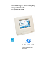
Internet Managed Thermostat (IMT)
Configuration Guide
(IMT350c and IMT350w)
Release 1.0
Part No. 600-03001-350, Rev. 1
August 2010
Copyright
Beta Draft Confidential
Copyright © 2010 Proliphix, Inc. All Rights Reserved.
The following are trademarks of Proliphix, Inc.:
All other trademarks are the property of their respective owners.
This document contains information that is the property of Proliphix, Inc. This document may not be
copied, reproduced, reduced to any electronic medium or machine readable form, or otherwise
duplicated, and the information herein may not be used, disseminated or otherwise disclosed, except with
the prior written consent of Proliphix, Inc.
ii
Internet Managed Thermostat Configuration Guide, Release 1.0
Part No. 600-03001-350, Rev. 1
Beta Draft Confidential
Software License Agreement
License for Use of Proliphix Software
IMPORTANT NOTICE -- READ CAREFULLY: This License For Customer Use of the Proliphix
Remote Management Interface Software ("PROLIPHIX LICENSE") is the agreement which governs use
of the software of Proliphix Incorporated and its subsidiaries ("Proliphix") downloadable here from,
including computer software and associated printed materials ("PROLIPHIX SOFTWARE"). By
downloading, installing, or otherwise using the PROLIPHIX SOFTWARE, you agree to be bound by the
terms of this PROLIPHIX LICENSE. If you do not agree to the terms of this PROLIPHIX LICENSE, do
not download or run the PROLIPHIX SOFTWARE.
RECITALS
Use of Proliphix's products requires four elements: the Thermostat, the Thermostat FIRMWARE, the
Proliphix Remote Management Software and a personal computer. The PROLIPHIX SOFTWARE is
protected by copyright laws and international copyright treaties, as well as other intellectual property
laws and treaties. This PROLIPHIX LICENSE sets forth the terms and conditions of the SOFTWARE
LICENSE only.
DEFINITIONS
Customer. Customer means the entity or individual that uses the SOFTWARE.
GRANT OF
LICENSE
Rights and Limitations of Grant. Proliphix hereby grants Customer the following non-exclusive,
non-transferable right to use the SOFTWARE, with the following limitations:
Rights. Customer may use the SOFTWARE on one or more computers, and may not otherwise copy the
SOFTWARE. This PROLIPHIX LICENSE of SOFTWARE may be used concurrently on different
computers.
LIMITATIONS
No Reverse Engineering. Customer may not reverse engineer, decompile, or disassemble the
SOFTWARE, nor attempt in any other manner to obtain the source code.
No Separation of Components. The SOFTWARE is licensed as a single product. Its component parts
may not be separated for use on more than one computer, nor otherwise used separately from the other
parts.
No Rental. Customer may not rent or lease the SOFTWARE to someone else.
TERMINATION
This LICENSE will automatically terminate if Customer fails to comply with any of the terms and
conditions hereof. In such event, Customer will be prohibited from access to the SOFTWARE by
termination of Customer’s Remote Management Interface account.
Defensive Suspension. If Customer commences or participates in any legal proceeding against Proliphix,
then Proliphix may, in its sole discretion, suspend or terminate all license grants and any other rights
provided under this LICENSE during the pendency of such legal proceedings.
COPYRIGHT
All title and copyrights in and to the SOFTWARE (including but not limited to all images, photographs,
animations, video, audio, music, text, and other information incorporated into the SOFTWARE), the
accompanying printed materials, and any copies of the SOFTWARE, are owned by Proliphix, or its
suppliers. The SOFTWARE is protected by copyright laws and international treaty provisions.
Accordingly, Customer is required to treat the SOFTWARE like any other copyrighted material, except
as otherwise allowed pursuant to this LICENSE and that it may make one copy of the SOFTWARE
solely for backup or archive purposes.
APPLICABLE
LAW
This LICENSE shall be deemed to have been made in, and shall be construed pursuant to, the laws of the
Commonwealth of Massachusetts. The United Nations Convention on Contracts for the International Sale
of Goods is specifically disclaimed.
Internet Managed Thermostat Configuration Guide, Release 1.0
Part No. 600-03001-350, Rev. 1
iii
Software License Agreement
DISCLAIMER OF
WARRANTIES
AND
LIMITATION ON
LIABILITY
Beta Draft Confidential
No Warranties. TO THE MAXIMUM EXTENT PERMITTED BY APPLICABLE LAW, THE
SOFTWARE IS PROVIDED "AS IS" AND PROLIPHIX AND ITS SUPPLIERS DISCLAIM ALL
WARRANTIES, EITHER EXPRESSED OR IMPLIED, INCLUDING, BUT NOT LIMITED TO,
IMPLIED WARRANTIES OF MERCHANTABILITY AND FITNESS FOR A PARTICULAR
PURPOSE.
No Liability for Consequential Damages. TO THE MAXIMUM EXTENT PERMITTED BY
APPLICABLE LAW, IN NO EVENT SHALL PROLIPHIX OR ITS SUPPLIERS BE LIABLE FOR
ANY SPECIAL, INCIDENTAL, INDIRECT, OR CONSEQUENTIAL DAMAGES WHATSOEVER
(INCLUDING, WITHOUT LIMITATION, DAMAGES FOR LOSS OF BUSINESS PROFITS,
BUSINESS INTERRUPTION, LOSS OF BUSINESS INFORMATION, OR ANY OTHER
PECUNIARY LOSS) ARISING OUT OF THE USE OF OR INABILITY TO USE THE
SOFTWARE,EVEN IF PROLIPHIX HAS BEEN ADVISED OF THE POSSIBILITY OF SUCH
DAMAGES.
OTHER
iv
If any provision of this LICENSE is inconsistent with, or cannot be fully enforced under, the law, such
provision will be construed as limited to the extent necessary to be consistent with and fully enforceable
under the law. This LICENSE is the final, complete and exclusive agreement between the parties relating
to the subject matter hereof, and supersedes all prior or contemporaneous understandings and agreements
relating to such subject matter, whether oral or written. This LICENSE may only be modified in writing
signed by an authorized officer of Proliphix. Customer agrees that it will not ship, transfer or export the
SOFTWARE into any country, or use the SOFTWARE in any manner, prohibited by the United States
Bureau of Export Administration or any export laws, restrictions or regulations.
Internet Managed Thermostat Configuration Guide, Release 1.0
Part No. 600-03001-350, Rev. 1
Technical
Support
When contacting Proliphix, Inc. for technical assistance, please have the following information available:
Product model and serial number.
Type of heating/cooling system (example: gas, oil, or electric; warm air, hot water, heat pump,
steam or gravity).
Location and number of wires attached to your Proliphix thermostat.
For additional assistance, please contact Proliphix, Inc. Technical Support,
9:00 AM to 5:00 PM Eastern Time Monday to Friday:
Web: www.proliphix.com
Email: [email protected]
Telephone: 1-978-692-3375
Fax: 978-692-3378
Warranty
Information
Proliphix, Inc. warrants its products to be free from manufacturing defects in materials and workmanship
under normal use for a period of 3 years for the IMT series thermostats from the date of purchase.
Proliphix shall not be liable to honor the terms of this warranty if the product has been used in any other
application other than that for which it was intended, or if it has been subjected to misuse, accidental damage,
acts of God, modification, or improper installation procedures. Furthermore, this warranty covers only
products which have all original and unaltered markings and labels (serial numbers, model numbers, etc.) of
manufacture. This limited warranty does not cover the repair of cracked, scratched, broken or modified
plastics; other cosmetic damage; or parts that have been altered, defaced or removed; or the scratching,
cracking or breakage of the product.
This warranty is not transferable.
THE FOREGOING WARRANTIES ARE THE SOLE AND EXCLUSIVE WARRANTIES EXPRESSED OR
IMPLIED GIVEN BY PROLIPHIX IN CONNECTION WITH THE PRODUCT, AND PROLIPHIX
DISCLAIMS ALL IMPLIED WARRANTIES, INCLUDING IMPLIED WARRANTIES OF
MERCHANTABILITY, FITNESS FOR A PARTICULAR PURPOSE AND NONINFRINGEMENT OF
THIRD PARTY RIGHTS. PROLIPHIX DOES NOT PROMISE THAT THE PRODUCT IS ERROR-FREE
OR WILL OPERATE WITHOUT INTERRUPTION. PROLIPHIX WILL NOT BE LIABLE FOR
INCIDENTAL OR CONSEQUENTIAL DAMAGES OR FOR ANY OTHER LOSSES, EXPENSES OR
DAMAGES RELATING TO PRODUCT DEFECTS OR FAILURES. CUSTOMER'S SOLE REMEDY,
AND PROLIPHIX'S SOLE OBLIGATION, WITH RESPECT TO ANY PRODUCT DEFECTS OR
FAILURES (REGARDLESS OF WHETHER YOUR CLAIM IS ASSERTED IN CONTRACT, TORT,
STRICT LIABILITY OR OTHERWISE) SHALL BE (AT PROLIPHIX'S SOLE OPTION) REPAIR,
REPLACEMENT OR REFUND OF THE PRICE PAID. IN NO EVENT WILL PROLIPHIX'S LIABILITY
WITH RESPECT TO A PRODUCT, EXCEED THE PRICE PAID FOR SUCH PRODUCT.
This warranty statement supersedes all previous warranties.
This warranty extends to products purchased directly from Proliphix or an authorized Proliphix agent, dealer,
distributor, or reseller.
Material
Return
Procedure
No merchandise may be returned for credit, exchange, or service without prior authorization from Proliphix.
To obtain warranty service for Proliphix products, contact Proliphix Customer Service (1-866-475-4846) and
request a Return Material Authorization (RMA) number.
Products may be returned for credit, exchange, or service with a Proliphix RMA number and with proof of
purchase. Enclose a note explaining the symptoms of the problem, stating the RMA number, and the name,
address and phone number of the company or individual contact.
Authorized returns must be shipped prepaid to Proliphix at:
Proliphix, Inc.
3 Lan Drive
Westford, MA 01886
Internet Managed Thermostat Configuration Guide, Release 1.0
Part No. 600-03001-350, Rev. 1
v
Beta Draft Confidential
The RMA number must be clearly marked on the outside of the package. Products received without an RMA
number or without shipping prepaid will be subject to refusal by Proliphix. Proliphix reserves the right to
charge a 15% restocking fee plus shipping costs on any products returned without an RMA.
Return shipping charges following repair of items under warranty shall be paid by Proliphix via standard
ground carrier. In the event that repairs are found to be non-warranty, return shipping charges will be paid by
the purchaser.
vi
Internet Managed Thermostat Configuration Guide, Release 1.0
Part No. 600-03001-350, Rev. 1
Beta Draft Confidential
Contents
Contents
Preface
Audience xi
Conventions xii
Technical Publications xiii
Technical Support xiii
Proliphix Welcomes Your Comments xiv
Chapter 1
Overview
DHCP Assigned IP Addresses 1-1
Connecting the Thermostat to the Local Network 1-2
Remote Management 1-2
Determining the IMT350 IP Address 1-2
Accessing the Web Interface 1-3
Logging In to the Thermostat 1-4
Chapter 2
Configuring the Thermostat Using the Web Interface
Control Page 2-2
HVAC 2-2
Usage Statistics 2-6
Schedules Page 2-8
HVAC 2-8
Schedule Settings 2-8
Calendar 2-10
Special Days 2-11
Alarms Page 2-17
Zone 2-17
Wired Sensors 2-20
Sensors Page 2-22
Advanced Page 2-24
HVAC Settings 2-24
Override Settings 2-29
Network Page 2-32
General 2-32
Wireless 2-35
Remote Access 2-37
Statistics 2-39
Admin Page 2-40
General 2-40
Date and Time 2-42
Password Settings 2-44
Restart 2-45
Software Update 2-46
Internet Management Thermostat Configuration Guide, Release 1.0
Part No. 600-03001-350, Rev. 1
vii
Contents
viii
Beta Draft Confidential
Internet Management Thermostat Configuration Guide, Release 1.0
Part No. 600-03001-350, Rev. 1
Beta Draft Confidential
Figures
List of Figures
Figure 1-1
Figure 2-1
Figure 2-2
Figure 2-3
Figure 2-4
Figure 2-5
Figure 2-6
Figure 2-7
Figure 2-8
Figure 2-9
Figure 2-10
Figure 2-11
Figure 2-12
Figure 2-13
Figure 2-14
Figure 2-15
Figure 2-16
Figure 2-17
Figure 2-18
Figure 2-19
Figure 2-20
Figure 2-21
Figure 2-22
Figure 2-23
Figure 2-24
Figure 2-25
Figure 2-26
Administrator Authentication Window 1-4
Control - HVAC Page 2-2
Control - Usage Statistics Page 2-6
Schedules - HVAC - Schedule Settings Page 2-8
Schedules - HVAC - Calendar Page 2-11
Schedule - HVAC - Special Days Page 2-12
Add Special Days Schedule 2-13
Special Days - Example A 2-14
Special Days - Example B 2-14
Special Days - Example C 2-15
Edit Special Day Schedule 2-16
Alarms - Zone Page 2-17
Alarms - Wired Sensors Page 2-20
Sensors Page 2-22
Advanced - General Settings Page - Fuel Burner 2-24
Advanced - General Settings Page - Heat Pump 2-25
Advanced - Override Settings Page 2-29
Network - Warning: Network Configuration 2-32
Network - General Page 2-33
Network - Wireless Page 2-35
Network - Remote Access Page 2-37
Network - Statistics Page 2-39
Admin - General Page 2-40
Admin - Date and Time Page 2-42
Admin - Password Settings Page 2-44
Admin - Restart Page 2-45
Admin - Software Update Page 2-46
Internet Management Thermostat Configuration Guide, Release 1.0
Part No. 600-03001-350, Rev. 1
ix
Beta Draft Confidential
Contents
List of Tables
Table 1-1
Table 2-1
Table 2-2
Table 2-3
Table 2-4
Table 2-5
Table 2-6
Table 2-7
Table 2-8
Table 2-9
Table 2-10
Table 2-11
Table 2-12
Table 2-13
Table 2-14
x
IMT350 Features 1-1
Control - HVAC Field Descriptions 2-3
Control - Usage Statistics Field Descriptions 2-6
Schedules-Daily Profile Definitions Field Descriptions 2-9
Alarms - Zone Field Descriptions 2-18
Alarms - Wired Sensors Field Descriptions 2-21
Sensors Field Descriptions 2-22
Advanced Settings Fields - HVAC Field Descriptions 2-26
Advanced - Override Settings Field Descriptions 2-30
Network - General Field Descriptions 2-33
Network - Wireless Field Descriptions 2-35
Network - Remote Access Field Descriptions 2-37
Admin - General Field Descriptions 2-41
Admin - Date and Time Field Descriptions 2-43
Admin - Password Settings Field Descriptions 2-44
Internet Management Thermostat Configuration Guide, Release 1.0
Part No. 600-03001-350, Rev. 1
Beta Draft Confidential
Preface
The Internet Managed Thermostat Configuration Guide describes how to control and
configure your IMT350 thermostat using a standard web browser such as Firefox or
Internet Explorer.
Audience
This guide is intended for managers and/or facilities managers or those responsible for
managing multiple devices remotely in small or medium size buildings, multiple
buildings, or corporate environments.
As a reader of this guide, you should be familiar with the use of an Internet browser
(for example Internet Explorer or Firefox) and have a working knowledge of general
data networking principles. You should have prior experience with establishing a local
area network (LAN) in either a home or office.
Internet Managed Thermostat Configuration Guide, Release 1.0
Part No. 600-03001-350, Rev. 1
xi
Beta Draft Confidential
Preface
Conventions
This guide uses the following conventions, when applicable:
Description
Convention and Example
Commands or keywords, file or path names
Boldface font
Variable parameters for which you supply values
<courier italics>
Options and arguments for which you supply values
[]
Information that the user must enter
Courier Bold font
Screen messages or system output
Courier Regular font
Selecting a menu item
Menu => Option
Book titles, new terms, and emphasized text
Italics
Additional information that may apply to the subject text.
Note
Proceed carefully to avoid possible equipment damage or data loss.
Caution
Proceed carefully to avoid possible personal injury.
Warning
Provide helpful suggestions.
Tip
xii
Internet Managed Thermostat Configuration Guide, Release 1.0
Part No. 600-03001-350, Rev. 1
Beta Draft Confidential
Preface
Technical Publications
Customers can obtain product documentation on our web site at
http://www.proliphix.com/.
Note
Documentation is available for currently supported product releases.
Documentation is available in Adobe PDF format. You can view PDFs online
using the Adobe Reader ® 6.0 or later. To download the latest version of the Adobe
Reader software from the Adobe web site, click
http://www.adobe.com/products/acrobat/readstep2.html.
Technical Support
Proliphix Technical Support provides technical support between the hours of 9:00 AM
and 5:00 PM Eastern Time, Monday through Friday. Extended 7/24 contracts are
available.
When contacting Proliphix Technical Support, please have the following information
available:
Product model and serial number
Type of heating/cooling system (for example, gas, oil, or electric; warm air, hot
water, heat pump, steam or gravity)
Location and number of wires attached to the Proliphix thermostat
To contact Proliphix Technical Support:
Proliphix, Inc.
www.proliphix.com
3 Lan Drive
Westford, MA 01886
E-mail: [email protected]
Telephone support
1-978-692-3375
Fax: Attention Proliphix Technical Support
1-978-692-3378
Internet Managed Thermostat Configuration Guide, Release 1.0
Part No. 600-03001-350, Rev. 1
xiii
Preface
Beta Draft Confidential
Proliphix Welcomes Your Comments
You can mail, e-mail, or fax your comments. Please include the document part
number in the subject line of your e-mail or fax message.
E-mail: [email protected]
Fax: Attention Technical Publications
978-692-3378
Proliphix, Inc.
Technical Publications
3 Lan Drive
Westford, MA 01886
xiv
Internet Managed Thermostat Configuration Guide, Release 1.0
Part No. 600-03001-350, Rev. 1
Beta Draft Confidential
1
Chapter
Overview
This chapter gives an overview of the Proliphix Internet Managed Thermostats (IMT)
Series Network Thermostats, as well as how to access the IMT350 using a Web
browser.
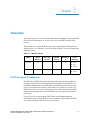
The IMT350 series of thermostats are powered by either Proliphix Ethernet Power
Adapters, Power over Ethernet, or via 24Vac from the HVAC system, and include the
following features:
Table 1-1
IMT350 Features
Model
Wired
Ethernet
IMT350c
X
IMT350w
802.11 b/g
wireless
Humidity
Sensing
Aux Relays
(2)
X
X
X
X
X
Power
Method(s)
EPA
PoE
HVAC
HPA
HVAC
DHCP Assigned IP Addresses
The IMT350c and IMT350w thermostat ship directly from the factory enabled to
perform as a Dynamic Host Configuration Protocol (DHCP) client. DHCP is an
established standard used to assign IP addresses automatically after each network
device is inserted into the network or when the device experiences a power cycle.
DHCP allows devices on your local network to receive their Internet Protocol (IP)
addresses automatically from an attached DHCP server typically located within a
local router.
If your file server or router supports DHCP, then your Proliphix thermostat
automatically retrieves an IP Address, Gateway Address, Subnet Mask, and DNS
server address from the DHCP server on your network.
Internet Management Thermostat Configuration Guide, Release 1.0
Part No. 600-03001-350, Rev. 1
1-1
Beta Draft Confidential
CHAPTER 1: Overview
Proliphix strongly recommends that a DHCP server be installed and operational
in your network prior to installing the thermostat.
If a DHCP server is unavailable on your network, your thermostat will default to
the 169.254.111.111 IP address. Note that this address is not unique to your
network if more than one thermostat is installed on a network without a DHCP
server. That is, there will be multiple thermostats on the network with the same IP
address (i.e. 169.254.111.111). Addressing conflicts will exist and most of the
thermostats will be inaccessible. You can use the lcd interface to set the IMT350 to
a static IP address if no DHCP server is available.
Note
Connecting the Thermostat to the Local Network
This section describes how to connect your IMT350c and IMT350w thermostats to
your local data network. This connection enables you to conveniently and efficiently
configure your thermostat using a browser on your laptop or desktop personal
computer. If a broadband connection is available on your local network, you can also
remotely manage and configure your thermostat via the Internet.
To connect the thermostat to your local network:
For the IMT350c, use a standard Ethernet patch cable and complete the
connection of your thermostat(s) to the local switch or router. Your thermostat(s)
should automatically communicate with the local DHCP server and be assigned a
unique IP address.
For the IMT350w, use the lcd interface and configure the wireless settings to
match your local wireless network.
Remote Management
You can manage the IMT350c and IMT350w thermostats using a web browser on a
local area network (LAN) or remotely though the Internet after proper authentication
at the Proliphix Web Site (www.proliphix.com).
Determining the IMT350 IP Address
Your Proliphix IMT350 ships from the factory capable to support the DHCP mode for
assigning an IP address to your thermostat. See the DHCP Assigned IP Addresses
(page 1-1) for more information.
Before you access and control your Proliphix IMT350 through either the lcd screen or
more comprehensively through the Web browser, you must know the IP address of the
thermostat.
To retrieve the IP address on the lcd screen on the front of the thermostat:
1
1-2
Press the Proliphix logo on the bottom right side of the lcd screen.
Internet Management Thermostat Configuration Guide, Release 1.0
Part No. 600-03001-350, Rev. 1
Beta Draft Confidential
2
Press Network.
3
Press IP Address.
Accessing the Web Interface
The IP Address screen displays the Address Method and URL (IP Address).
Accessing the Web Interface
To access the initial Web page of the thermostat, enter the unique IP address initially
assigned via DHCP in your browser window. For example:
http://192.168.0.247
Where 192.168.0.247 is a unique IP address initially assigned via DHCP.
Most of the Web pages conform to a standard format which is maintained for both
local and remote thermostat access. A banner at the top of each page contains the
following information for each thermostat:
Current date and time
Host name of the thermostat
Model number
Each thermostat page also includes tabs which enable direct access to all other Web
pages on the thermostat. The Web browser displays each page in a table format. Each
feature table is organized by rows of functions, in a left to right direction as follows:
Field name
Function status
Function control (text boxes and drop-down selections)
Internet Management Thermostat Configuration Guide, Release 1.0
Part No. 600-03001-350, Rev. 1
1-3
Beta Draft Confidential
CHAPTER 1: Overview
Logging In to the Thermostat
The IMT350 Series thermostats require password authentication prior to accessing the
Web pages that enable you to control or manage the thermostats. The username and
password is as follows:
Username: admin
Password: admin (default)
You can change each of these passwords within each account after the initial
authentication. For more information, see Password Settings (page 2-44).
Tip
To log in to the thermostat and access the Web pages:
1
Open a Web browser.
2
Enter the IP address of the thermostat. For example:
http://192.168.0.247
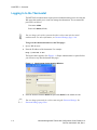
The login window appears. (See Figure 1-1.) Proper authentication is required before
you can access any other thermostat Web pages.
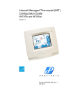
Figure 1-1
3
Note
1-4
Administrator Authentication Window
Enter the default username admin and password admin for the admin account.
You can change passwords for each account using the Password Settings. See
Password Settings (page 2-44).
Internet Management Thermostat Configuration Guide, Release 1.0
Part No. 600-03001-350, Rev. 1
Beta Draft Confidential
4
Logging In to the Thermostat
Click OK.
The default Control - HVAC page appears. See Figure 2-1 on page 2-2.
Note
In each Web page, you must click Submit to apply all changes made in the Control
column. Click Refresh to update the status.
Continue with the Control Page (page 2-2).
Internet Management Thermostat Configuration Guide, Release 1.0
Part No. 600-03001-350, Rev. 1
1-5
CHAPTER 1: Overview
1-6
Beta Draft Confidential
Internet Management Thermostat Configuration Guide, Release 1.0
Part No. 600-03001-350, Rev. 1
Beta Draft Confidential
Chapter
2
Configuring the Thermostat Using the Web
Interface
This chapter describes how to configure and monitor the thermostat through the web
browser using the IMT350 Web interface.
Internet Managed Thermostat Configuration Guide, Release 1.0
Part No. 600-03001-350, Rev. 1
2-1
Beta Draft Confidential
CHAPTER 2: Configuring the Thermostat Using the Web Interface
Control Page
The Control page displays tabs for the HVAC, AUX Relays, and Usage Statistics
pages.
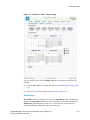
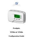
HVAC
The Control - HVAC page displays the HVAC zone status, schedule, and settings,
for example.
Figure 2-1
2-2
Control - HVAC Page
Internet Managed Thermostat Configuration Guide, Release 1.0
Part No. 600-03001-350, Rev. 1
Beta Draft Confidential
Control Page
Use Table 2-1 to configure the Control - HVAC fields.
Table 2-1
Control - HVAC Field Descriptions
Field
Description
Temperature
Zone Temperature
Displays the current temperature of the zone if temperature averaging is
disabled.
Average temperature of any combination of Local, Remote Sensor #1 (RS
#1), or Remote Sensor #2 (RS #2) if temperature averaging is enabled. (See
Advanced Page (page 2-24).)
In a range of -30°F(-34°C) to 199°F(95°C)
Also displays the current status of the Zone Temperature alarm. If an alarm
occurs, you must repair the condition which caused the alarm before
resetting the alarm. (See Alarms Page (page 2-17).)
Local Temperature
This field is blank if no Zone Temperature alarm exists.
Low Temperature Alert! – The temperature monitored within the
thermostat has dropped below the pre-set temperature threshold.
High Temperature Alert! – The temperature monitored within the
thermostat has risen above the pre-set temperature threshold.
Displays the current temperature of the local sensor. This field is disabled if
the local thermostat sensor is not included in temperature averaging.
In a range of 40°F(4.5°C) to 110°F(43.5°C)
Zone Humidity
Displays the current Zone Humidity.
In a range of 0% to 95%
Low Humidity Alert! – The humidity level monitored within the
thermostat has dropped below the pre-set humidity threshold.
High Humidity Alert! – The humidity level monitored within the
thermostat has risen above the pre-set humidity threshold.
RS1:
Sets the current temperature of RS1.
RS2:
Sets the current temperature of RS2.
Heat Setting
Displays the current temperature programmed for the heating system. This
field is disabled if the HVAC mode is set to Cool or Off. (See HVAC Mode
(page 2-5).) This field is not visible if the thermostat is configured to be a
cool-only controlling device. (See Advanced Page (page 2-24).)
To modify this field, use the drop-down menu to select a Heat Setting.
40°F(4.5°C) to 110°F(43.5°C)
Internet Managed Thermostat Configuration Guide, Release 1.0
Part No. 600-03001-350, Rev. 1
2-3
Beta Draft Confidential
CHAPTER 2: Configuring the Thermostat Using the Web Interface
Table 2-1
Control - HVAC Field Descriptions (Continued)
Field
Description
Cool Setting
Displays the current temperature programmed for the cooling (A/C) system.
This field is disabled if the HVAC mode is set to Heat or Off. (See HVAC
Mode (page 2-5).) This field is not visible if the thermostat is configured to
be a heat-only controlling device. (See Advanced Page (page 2-24).)
To modify this field, use the drop-down menu to select a Cool Setting.
40°F(4.5°C) to 110°F(43.5°C)
Fan Filter Change
Displays a reminder that the time interval between HVAC filter changes has
expired. The air filter(s) should be cleaned or replaced. You should change
the filter and then reset this timer. (See Alarms Page (page 2-17).)
This field is left blank if no filter change is required.
Required! – The HVAC filters require changing or cleaning.
Current Schedule
Daily Profile
Displays the current active scheduled Profile.
Event
Displays the current active Event.
Heat Setting
Morning
Day
Evening
Night
Displays the current Heat temperature setting as set within the current
schedule.
40°F(4.5°C) to 110°F(43.5°C)
Cool Setting
Displays the current Cool temperature setting as set within the current
schedule.
40°F(4.5°C) to 110°F(43.5°C)
Overrides
Away
Hold
Displays the current state for both the Heat and Cool Setting. To “Away”
the current settings indefinitely or for a prescribed period of time as set on
the Override Settings (page 2-29), use the drop-down menu and choose:
Enabled – Hold mode is enabled.
Off (default) – Away mode is disabled.
Displays the current state for both the Heat and Cool Setting. To “Hold” the
current settings indefinitely or for a prescribed period of time as set on the
Override Settings (page 2-29), use the drop-down menu and choose:
Enabled – Hold mode is enabled.
Off (default) – Hold mode is disabled.
Note: When Occupancy Override is visible, it displays the current state of
an active “Away” button activation.
2-4
Internet Managed Thermostat Configuration Guide, Release 1.0
Part No. 600-03001-350, Rev. 1
Beta Draft Confidential
Table 2-1
Control Page
Control - HVAC Field Descriptions (Continued)
Field
Description
HVAC Settings
HVAC State
Displays the current state of the heating or cooling system. If a state change
is made while viewing this page, click Refresh to update the status.
Heat – First stage heat is actively heating.
Aux Ht – First stage, second stage, and auxiliary heat are actively
heating. (Heat Pump)
Emergency Ht - Emergency heat source is heating.
Cool – First stage A/C is actively cooling.
Off – Neither the heating system or cooling system is active (i.e. on).
HVAC Delay State
Displays the HVAC delay state. Delay can be in effect if the interstage delay
is set or if the compressor has been turned off within the last n minutes,
where n is the set time from the Compressor Delay on the Advanced/HVAC
page.
HVAC Mode
Displays and controls the current mode setting for the HVAC system. The
thermostat can be configured to control the heat system only, cool system
only, automatically change over between heating and cooling systems, or
control neither system.
Fan State
Fan Mode
Off – The thermostat is disabled from controlling either the heating or
cooling system.
Heat – Heating system only.
Cool – Cooling system only.
Auto – Automatic changeover between heating and cooling systems.
Emergency Heat - Forces the activation of an alternative heat source for
heat pumps.
Displays the current state of the HVAC fan.
Off – The operation of the fan is off.
On – The fan is operating.
Displays and controls the current state setting for the HVAC fan.
Auto – Heating or cooling system controls the operation of the fan.
On – User forces the fan to the on state independent of the operation of
the HVAC system.
Scheduled – The operation of the fan adheres to a schedule as defined by
the user on the schedule pages with the schedule profile definition. Note:
When in Scheduled mode, the fan continues to work in Auto mode as
well.
Internet Managed Thermostat Configuration Guide, Release 1.0
Part No. 600-03001-350, Rev. 1
2-5
Beta Draft Confidential
CHAPTER 2: Configuring the Thermostat Using the Web Interface
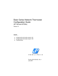
Usage Statistics
The Control - Usage Statistics page displays the usage information.
Figure 2-2
Control - Usage Statistics Page
Use Table 2-2 to configure the Control - Usage Statistics fields.
Table 2-2
Control - Usage Statistics Field Descriptions
Field
Description
Usage Counters
Heating
2-6
Displays thee Heat1relay minute activity counter. The Admin account user
can reset this field by checking the Last counter reset box.
Internet Managed Thermostat Configuration Guide, Release 1.0
Part No. 600-03001-350, Rev. 1
Beta Draft Confidential
Control Page
Field
Description
Fan/Filter
Displays the Fan/Filter relay minute activity counter, which is the number
of days, hours, and minutes since the Last counter reset box was checked
and submitted. The Admin account user can reset this field by checking the
Last counter reset box.
Cooling
Displays the Cool 1 relay minute activity counter, which is the number of
days, hours, and minutes since the Last counter reset box was checked. The
Admin account user can reset this field by checking the Last counter reset
box.
Counter Status and Control
Last counter reset
Check to return the Usage Counters to zero value (except Fan/Filter) after
clicking Submit.
Internet Managed Thermostat Configuration Guide, Release 1.0
Part No. 600-03001-350, Rev. 1
2-7
Beta Draft Confidential
CHAPTER 2: Configuring the Thermostat Using the Web Interface
Schedules Page
The Schedules page displays tabs for the HVAC pages.
HVAC
The Schedules - HVAC settings page displays the schedule information.
Schedule Settings
The Schedule Settings page displays the default daily Profiles and weekly schedule.
Figure 2-3
2-8
Schedules - HVAC - Schedule Settings Page
Internet Managed Thermostat Configuration Guide, Release 1.0
Part No. 600-03001-350, Rev. 1
Beta Draft Confidential
Schedules Page
Daily Profile Definitions
The thermostat scheduling feature is organized in a hierarchy. You use Profiles (up to
7) to classify the types of days that are used in the schedule. Each Profile is divided
into four events, each of which supports temperature settings for both heating and
cooling, and fan scheduling to provide periodic air flow.
Each Profile supports the following four non-overlapping events of time (within 24
hour period) in which you can independently specify heat, cool, and fan schedules.
Morning
Day
Evening
Night
Figure 2-3 on page 2-8 displays the Profile table. The Web page displays the Event
period and Start Time within each row of the table. The Web page also displays the
heat and cool settings for each Event period in each Profile. Although the thermostat
ships from the factory with pre-set Event settings, you can change these settings by
selecting the appropriate definition from the drop-down menu.
Use Table 2-3 to configure the Daily Profile Definitions.
Table 2-3
Schedules-Daily Profile Definitions Field Descriptions
Field
Description
Daily Profile Definitions
Profile Name
Use the drop-down menu to select the appropriate profile. The profile name
displays in the header. Click Color and select a color to color-code the profile for
easy recognition.
Event
Displays one of four time periods of the 24-hour day.
Start Time
Use the drop-down menu to modify the time period in 5-minute increments.
Includes AM/PM indicator.
Heat
Use the drop-down menu to select a heat temperature setback setting between
40°F(4.5°C) to 110°F(43.5°C)
Cool
Use the drop-down menu to select a cool temperature setback setting between
40°F(4.5°C) to 110°F(43.5°C)
Internet Managed Thermostat Configuration Guide, Release 1.0
Part No. 600-03001-350, Rev. 1
2-9
Beta Draft Confidential
CHAPTER 2: Configuring the Thermostat Using the Web Interface
Table 2-3
Schedules-Daily Profile Definitions Field Descriptions (Continued)
Field
Description
Fan Schedule
Select the time in minutes for each hour of the Event in which the fan will be On.
The schedule begins on the hour and advances for the duration specified. Note that
within the hour of each Event but outside the schedule interval, the fan reverts to
AUTO mode to ensure proper operation for either a heating or cooling call to the
HVAC system. Select one of the following options:
Always Off
5 On / 15 Off
10 On / 10 Off
15 On / 5 Off
Always On
Default Weekly Schedule
In Figure 2-3 on page 2-8, the Default Weekly Schedule table provides a template
that you can use to apply the Profiles to each day of the week. The Web page applies
this weekly template to every week in each month that is visible in the Calendar
View at the bottom of the Calendar (page 2-10) page.
To edit the Default Weekly Schedule, use the drop-down menu and select the
appropriate Profile.
Calendar
The Calendar View table displays the Profile settings for each day of the month.
2-10
Internet Managed Thermostat Configuration Guide, Release 1.0
Part No. 600-03001-350, Rev. 1
Beta Draft Confidential
Figure 2-4
Schedules Page
Schedules - HVAC - Calendar Page
You can modify any day in the Calendar View table using either of the following
methods:
Click the date within the calendar and continue with Adding Special Days (page
2-12).
Click Special Days and continue with Special Days (page 2-11).
Special Days
Special Days entries are organized as rows in the Special Days table. The Web page
supports 30 Special Days table entries, each comprised of a start date entered in the
Month, Day, and Year fields. In each row, you can enter one or more days as a
duration for that entry. Durations cannot exceed 60 days.
Internet Managed Thermostat Configuration Guide, Release 1.0
Part No. 600-03001-350, Rev. 1
2-11
Beta Draft Confidential
CHAPTER 2: Configuring the Thermostat Using the Web Interface
Figure 2-5
Schedule - HVAC - Special Days Page
To add a special day(s), click Add Special Day and continue with Adding Special
Days.
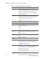
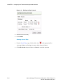
Adding Special Days
From the Add Special Days Schedule page, you can select any day(s) of the current
or future month, modify the information, and assign a Profile different from what is
specified in the Default Weekly Schedule (page 2-10).
2-12
Internet Managed Thermostat Configuration Guide, Release 1.0
Part No. 600-03001-350, Rev. 1
Beta Draft Confidential
Figure 2-6
Schedules Page
Add Special Days Schedule
To add a special day(s):
1
Enter a Name for the special day(s).
2
Specify the Month, Day, and Year.
3
Enter the appropriate day(s) duration.
4
Select the appropriate Daily Profile to Use.
5
Click Submit.
You can enter this information in the Special Days table using either of the following
methods:
Configure the Profile (see Daily Profile Definitions (page 2-9)) to reflect the
desired settings. Click directly on the date on the Calendar. The Add Special Day
Schedule page appears and automatically populates the Start Date and End
Date. One day is the default duration, but you can change this field to any number
of days less than the 60 day maximum. Modify the fields as necessary. Click
Submit. The Special Day displays on the Special Days table and Calendar.
Configure the Profile (see Daily Profile Definitions (page 2-9)) to reflect the
desired settings. From the Special Days page, click Add Special Days. The Add
Special Days Schedule appears. Modify the fields as necessary. Click Submit.
The Special Day displays on the Special Days table and Calendar.
Internet Managed Thermostat Configuration Guide, Release 1.0
Part No. 600-03001-350, Rev. 1
2-13
Beta Draft Confidential
CHAPTER 2: Configuring the Thermostat Using the Web Interface
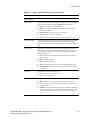
Example
Figure 2-7 shows an example of adding additional Special Days to the thermostat
schedule of a week-long period from August 9, 2010 through August 13, 2010.
Figure 2-7
Special Days - Example A
1
From the Special Days page (see Special Days (page 2-11)), click Add Special Day.
2
Enter a Name and Schedule information for the special day(s).
3
Select the appropriate Daily Profile to Use.
4
Click Submit.
The Special Day entry (for 5 days total) displays on the Special Days and Calendar
pages.
Figure 2-8
2-14
Special Days - Example B
Internet Managed Thermostat Configuration Guide, Release 1.0
Part No. 600-03001-350, Rev. 1
Beta Draft Confidential
Figure 2-9
Schedules Page
Special Days - Example C
Special Days (5)
Modifying Special Days
1
From the Special Days page, click the pencil icon
display the Edit Special Day Schedule page.
Internet Managed Thermostat Configuration Guide, Release 1.0
Part No. 600-03001-350, Rev. 1
on the appropriate line to
2-15
Beta Draft Confidential
CHAPTER 2: Configuring the Thermostat Using the Web Interface
Figure 2-10
Edit Special Day Schedule
2
Edit the fields as necessary.
3
Click Submit.
Deleting Special Days
1
From the Special Days page, click the delete icon
on the appropriate line.
A message displays confirming you want to delete the special day(s).
2
2-16
Click OK to delete the special day(s) or Cancel to cancel the operation.
Internet Managed Thermostat Configuration Guide, Release 1.0
Part No. 600-03001-350, Rev. 1
Beta Draft Confidential
Alarms Page
Alarms Page
The Alarms page displays tabs for the Zone and Wired Sensors pages.
Zone
The Alarms - Zone page displays the zone temperature, humidity, and filter change
reminder.
Figure 2-11
Alarms - Zone Page
Internet Managed Thermostat Configuration Guide, Release 1.0
Part No. 600-03001-350, Rev. 1
2-17
Beta Draft Confidential
CHAPTER 2: Configuring the Thermostat Using the Web Interface
Use Table 2-4 to configure the Alarms - Zone page fields.
Table 2-4
Alarms - Zone Field Descriptions
Field
Description
Zone Temperature Alarms
Low Temperature Limit
Select a value or Disabled to indicate the low temperature
threshold detection status.
The value set by this parameter is monitored by the thermostat
and compared against the current Zone Temperature. If the
current Zone Temperature falls below this value, an alarm
condition is set and the status is displayed on the HVAC (page
2-2) page.
Disabled (default) – No low temperature limit is set.
-30°F(-34.5°C) to 200°F(93°C)
This is a major (red) alarm condition.
Present for
Enter how long the condition must be in effect before the alarm
is triggered. Note that the default is 0 minutes and the maximum
time allowed is 240 minutes.
Alarm generated at
Day and time the alarm was generated.
High Temperature Limit
Select a value or Disabled to indicate the high temperature
threshold detection status.
The value set by this parameter is monitored by the thermostat
and compared against the current Zone Temperature. If the
current Zone Temperature rises above this value, an alarm
condition is set and the status is displayed on the HVAC (page
2-2) page.
Disabled (default) – No high temperature limit is set.
-30°F(-34.5°C) to 200°F(93°C)
This is a major (red) alarm condition.
2-18
Present for
Enter how long the condition must be in effect before the alarm
is triggered. Note that the default is 0 minutes and the maximum
time allowed is 240 minutes.
Alarm generate at
Day and time the alarm was generated.
Internet Managed Thermostat Configuration Guide, Release 1.0
Part No. 600-03001-350, Rev. 1
Beta Draft Confidential
Table 2-4
Alarms Page
Alarms - Zone Field Descriptions (Continued)
Field
Description
Zone Humidity Alarms
Low Humidity Limit
Select a value or Disabled to indicate the low humidity threshold
detection status.
This value is monitored by the thermostat and compared against
the current Relative Humidity. If the current Relative
Humidity rises above this value, an alarm condition is set and
the status is displayed on the HVAC (page 2-2) page.
Disabled (default) – No high humidity limit is set.
0%RH to 95%RH – High Humidity Limit in 5%
increments.
This is a major (red) alarm condition.
High Humidity Limit
Select a value or Disabled to indicate the high humidity
threshold detection status.
This value is monitored by the thermostat and compared against
the current Relative Humidity. If the current Relative
Humidity rises above this value, an alarm condition is set and
the status is displayed on the HVAC (page 2-2) page.
Disabled (default) – No high humidity limit is set.
0%RH to 95%RH – High Humidity Limit in 5%
increments.
This is a major (red) alarm condition.
Fan Filter Change
Fan Filter Change Reminder
Specifies if fan filter change reminder is enabled.
Change Interval (runtime hours)
Select an interval in hours to remind you that the HVAC system
requires maintenance. This feature allows you to set time
intervals between changing and/or cleaning the HVAC air filter.
If enabled, an alarm condition is set after the pre-set interval has
expired, and is displayed on the HVAC (page 2-2) page.
This is a minor (yellow) alarm condition.
Usage to Date
Displays a running tally of hours and minutes which have
elapsed since the previous Last Replaced date. If this value is
greater than the preset hours, it is displayed in red and an alarm
is generated indicating that the Change Interval has expired.
Last Replaced
Displays the date and time the Filter replaced box was checked
and restarts the interval set within the Change Interval field.
Internet Managed Thermostat Configuration Guide, Release 1.0
Part No. 600-03001-350, Rev. 1
2-19
Beta Draft Confidential
CHAPTER 2: Configuring the Thermostat Using the Web Interface
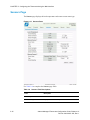
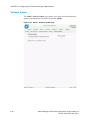
Wired Sensors
The Alarms - Wired Sensors page displays if any of the three remote sensors are
configured.
Figure 2-12
2-20
Alarms - Wired Sensors Page
Internet Managed Thermostat Configuration Guide, Release 1.0
Part No. 600-03001-350, Rev. 1
Beta Draft Confidential
Alarms Page
Use Table 2-5 to configure the Alarms - Wired Sensors page fields.
Table 2-5
Alarms - Wired Sensors Field Descriptions
Field
Description
RS1 and RS2
Low Temperature Limit
Select a value or Disabled to indicate the low temperature
threshold detection status.
The value set by this parameter is monitored by the thermostat
and compared against the current Zone Temperature. If the
current Zone Temperature falls below this value, an alarm
condition is set and the status is displayed on the HVAC (page
2-2) page.
Disabled (default) – No low temperature limit is set.
-30°F(-34.5°C) to 200°F(93°C)
This is a major (red) alarm condition.
Present for
Enter how long the condition must be in effect before the alarm
is triggered. Note that the default is 0 minutes and the maximum
time allowed is 240 minutes.
High Temperature Limit
Select a value or Disabled to indicate the high temperature
threshold detection status.
The value set by this parameter is monitored by the thermostat
and compared against the current Zone Temperature. If the
current Zone Temperature rises above this value, an alarm
condition is set and the status is displayed on the HVAC (page
2-2) page.
Disabled (default) – No high temperature limit is set.
-30°F(-34.5°C) to 200°F(93°C)
This is a major (red) alarm condition.
Present for
Enter how long the condition must be in effect before the alarm
is triggered. Note that the default is 0 minutes and the maximum
time allowed is 240 minutes.
Internet Managed Thermostat Configuration Guide, Release 1.0
Part No. 600-03001-350, Rev. 1
2-21
Beta Draft Confidential
CHAPTER 2: Configuring the Thermostat Using the Web Interface
Sensors Page
The Sensors page displays the local temperature and remote sensor name/type.
Figure 2-13
Sensors Page
Use Table 2-6 to complete the Sensors page fields.
Table 2-6
Sensors Field Descriptions
Field
Description
Local Temperature
Current Reading
2-22
Displays the current local temperature.
Internet Managed Thermostat Configuration Guide, Release 1.0
Part No. 600-03001-350, Rev. 1
Beta Draft Confidential
Table 2-6
Sensors Page
Sensors Field Descriptions (Continued)
Field
Description
Sensor Correction
Indicate the calibration or temperature offset compensation for
this remote thermal sensor. Offset adjustments are added or
subtracted from the actual temperature read from this sensor and
displayed as the apparent temperature.
-10°F (-5.5 °C) through +10°F (5.5C)
The default is 0.
Sensor Averaging
Specifies to include sensor averaging.
Remote Sensor 1 and 2
Sensor Name
Displays the Name (15 characters) for the external thermal
sensor #1 and #2.
RS1 / RS2
The default is RS1/ RS2.
Type
Select the remote sensor type: thermistor or contact to determine
whether or not a temperature sensor or dry contact closure
source is connected to this sensor. (Consult the Proliphix web
site for a list of sensors available in either type.)
Thermistor – Thermistor-based thermal sensors.
Contact – Contact-based connections.
The Contact closure option can be used to sense if a door is
open or closed for greater than the number of minutes set on
the Alarms page and then notify you via an alert e-mail. For
example, this option is often used in food service
applications but can be used for any situation where you
need to monitor a Contact closure.
Group
Unconfigured (default)
Specifies if the sensor is assigned to Indoor Temp or Outdoor
Temp.
Note: If one ore more of the remote sensors are configured as
within the Outdoor Temp group, only the first (that is, RS1 then
RS2, in that order) are displayed on the thermsotat’s LCD
screen.
Current Reading
Displays the current local temperature.
Sensor Correction
Indicate the calibration or temperature offset compensation for
this remote thermal sensor. Offset adjustments are added or
subtracted from the actual temperature read from this sensor and
displayed as the apparent temperature.
-10°F (-5.5 °C) through +10°F (5.5C)
The default is 0.
Internet Managed Thermostat Configuration Guide, Release 1.0
Part No. 600-03001-350, Rev. 1
2-23
Beta Draft Confidential
CHAPTER 2: Configuring the Thermostat Using the Web Interface
Advanced Page
The Advanced page displays tabs for the General Settings and Override Settings
pages.
HVAC Settings
The Advanced - General Settings page displays the HVAC system information.
Figure 2-14
2-24
Advanced - General Settings Page - Fuel Burner
Internet Managed Thermostat Configuration Guide, Release 1.0
Part No. 600-03001-350, Rev. 1
Beta Draft Confidential
Figure 2-15
Advanced Page
Advanced - General Settings Page - Heat Pump
Use Table 2-7 to configure the Advanced Settings fields.
Internet Managed Thermostat Configuration Guide, Release 1.0
Part No. 600-03001-350, Rev. 1
2-25
Beta Draft Confidential
CHAPTER 2: Configuring the Thermostat Using the Web Interface
Table 2-7
Advanced Settings Fields - HVAC Field Descriptions
Field
Description
HVAC System Type
Select the type of HVAC system, either Fuel Burner (default) or
Heat Pump HVAC systems as follows:
Fuel Burner (default) – The HVAC system burns fossil
fuels (e.g. gas or oil). Typically the system includes either an
oil or gas fired boiler or furnace. See Figure 2-14 on
page 2-24 and continue with If Your HVAC System is a Fuel
Burner (page 2-26).
Heat Pump – Specifies that the HVAC system is based on
an electric compressor. See Figure 2-15 on page 2-25 and
continue with If Your HVAC System is a Heat Pump (page
2-26).
If Your HVAC System is a Fuel Burner
Heat Control
Cool Control
Select the HVAC control for this thermostat. This parameter
describes the thermostat capability to control a single stage or
dual stage heating system. The thermostat can also be disabled
from controlling a heating system and instead operate as a
cool-only thermostat.
Disable – No heating system exists. (A/C only thermostat.)
1H – Enables the heating system as a standard single stage
system.
Specify the HVAC control of this thermostat. This parameter
describes the thermostat’s capability to control a single stage or
dual stage cooling system. The thermostat can also be disabled
from controlling a cooling system and instead operate as a
heat-only thermostat. (See Heat Control (page 2-26).)
Disable – Specifies that there is no cooling system present.
(heat-only thermostat.)
1C – Enables the cooling system as a standard single stage
system.
If Your HVAC System is a Heat Pump
Reverse Valve Polarity
2-26
Enables you to control the direction of the heating and cooling
modes.
O - Reverse for Cool – Indicates that the heat pump
normally runs in heat mode and when the reversing valve is
activated then the heat pump will run in cooling mode.
B - Reverse for Heat – Indicates that the heat pump
normally runs in cool mode and when the reversing valve is
activated then the heat pump will run in heating mode.
Internet Managed Thermostat Configuration Guide, Release 1.0
Part No. 600-03001-350, Rev. 1
Beta Draft Confidential
Table 2-7
Advanced Page
Advanced Settings Fields - HVAC Field Descriptions (Continued)
Field
Description
Auxiliary Heat
Specifies a secondary source of heat outside the heat pump
system, for example, electric baseboard or a gas furnace.
Note: In a dual stage heat pump, Auxilliary Heat is available
only after the 2nd stage is active.
Disabled – Disables Auxiliary Heat.
Enabled – Auxilliary Heat can be used while the heat pump
compressor is active.
Enabled without Compressor – Disables the compressor
when Auxiliary Heat is active.
Aux Heat Offset
Specifies the setting in degrees that the air temperature has to be
below the zone temperature to activate the Aux Heat source. The
default value is -2F, for example if the heat setpoint is 70F and
the air temperature drops below 68F the Aux Heat source will be
turned on. The range is from -6 to 0.
Aux Heat Delay
Specifies the delay between the active heat pump cycle and
activation of the Auxiliary Heat source.
Heat Control
Specifies the HVAC control of this thermostat. This parameter
describes the thermostat’s capability to control a heat pump
system. The thermostat can also be disabled from controlling a
heating system and instead operate as a cool-only thermostat.
Cool Control
Disabled – Specifies that there is no heating system present.
(A/C only thermostat.)
1H – Enables the heat pump as a standard single stage
heating system.
Specifies the HVAC control of this thermostat. This parameter
describes the thermostat’s capability to control a heat pump
system. The thermostat can also be disabled from controlling a
cooling system and instead operate as a heat-only thermostat.
Disable – Specifies that there is no cooling system present.
(Heat only thermostat.)
1C – Enables the heat pump as a standard single stage
cooling system.
Internet Managed Thermostat Configuration Guide, Release 1.0
Part No. 600-03001-350, Rev. 1
2-27
Beta Draft Confidential
CHAPTER 2: Configuring the Thermostat Using the Web Interface
Table 2-7
Advanced Settings Fields - HVAC Field Descriptions (Continued)
Field
Description
A/C Humidity Control
A/C Humidity Control
Select a relative humidity value from 10% to 90%. when
Enabled. When the measured RH rises above a preset threshold,
the HVAC cooling cycle is initiated. The cycle continues until
the humidity level falls 5% below the trigger level or until a heat
setpoint is encountered. When a heat setpoint is encountered, the
HVAC heating cycle is invoked. After the heat setpoint has been
satisfied, the HVAC cooling cycle (to satisfy humidity
requirements) is delayed for 5 minutes. Humidity control is
intended for moderate moisture control. High humidity
environments should also include secondary dehumidification
equipment.
Disabled – This feature is disabled and the A/C system may
not be used to reduce humidity.
Enabled – 10% – 90% - Humidity threshold expressed in
5% increments.
General Thermostat Settings
Temperature Scale
Fan on Heat
2-28
Select either the Fahrenheit or Celsius temperature scales.
Fahrenheit (default) – All thermostat temperature readings
and reporting are displayed in the Fahrenheit temperature
scale (°F).
Celsius – All thermostat temperature readings and reporting
are displayed in the Celsius temperature scale (°C).
Controls the fan state during heating cycles. In most HVAC
applications the hvac system will wait for the air to warm up
before turning on the fan to circulated the air and the thermostat
does not energize the fan (G) relay. There are some systems
with independent heat sources like electric coils in ducts that rely
on the thermostat to turn on the fan to circulate the air. In this
case you would need to enabel "Fan on Heat."
Enabled – The fan is forced ‘on’ during heat cycles.
Disabled – The fan is not forced on during heat cycles.
Internet Managed Thermostat Configuration Guide, Release 1.0
Part No. 600-03001-350, Rev. 1
Beta Draft Confidential
Advanced Page
Override Settings
The Advanced - Override Settings page displays the override cool and heat settings,
for example.
Figure 2-16
Advanced - Override Settings Page
Internet Managed Thermostat Configuration Guide, Release 1.0
Part No. 600-03001-350, Rev. 1
2-29
Beta Draft Confidential
CHAPTER 2: Configuring the Thermostat Using the Web Interface
Use Table 2-8 to configure the Override Settings fields.
Table 2-8
Advanced - Override Settings Field Descriptions
Field
Description
Hold
Allow Hold
Indicates if thermostat temperature setting are held independent
of schedule changes due to Event or Daily Profiles
advancements.
Hold Mode Duration
Enabled - Allow the temperature settings to be held for the
duration shown below.
Disabled - Do not allow the temperature settings to be held.
Specifies the time interval in which the thermostat temperature
setting are held independent of schedule changes due to Event or
Daily Profile advancements.
Perm – The Hold period is indefinite and the temperature
setting are “held” until the user removes this condition.
1, 2, 3, 8, 12, 24 Hrs –The amount of time in hours in which
the current temperature setting are “held” and inhibited from
change. The default interval is 3 Hrs.
Note: These durations are observed across Event boundaries.
Away Override Settings
Cool Setting
Displays the cool setpoint to be used while Away is active.
40°F(4.5°C) to 110°F(43.5°C)
Heat Setting
Displays the current temperature programmed for the heating
system.
40°F(4.5°C) to 110°F(43.5°C)
Fan Schedule
2-30
Specifies the time in minutes of each hour of the Event in which
the fan will be On. The schedule begins on the hour and
advances for the duration specified. Note that within the hour of
each Event but outside the schedule interval, the fan behaves the
same as AUTO mode to ensure proper operation for either a
heating or cooling call to the HVAC system. Select one of the
following options:
Always Off
5 On / 15 Off
10 On / 10 Off
15 On / 5 Off
Always On
Internet Managed Thermostat Configuration Guide, Release 1.0
Part No. 600-03001-350, Rev. 1
Beta Draft Confidential
Table 2-8
Advanced Page
Advanced - Override Settings Field Descriptions (Continued)
Field
Description
Duration
Specifies the time interval in which the thermostat temperature
setting are held independent of schedule changes due to Event or
Daily Profile advancements.
Until – The Away period is indefinite and the temperature
setting are “held” until the user removes this condition.
2, 4, 8, 12 hrs, 1, 2, 3, 4, 5, 6, 7 days, 2, 3 weeks –The
amount of time in which the current temperature setting are
set as “Away” and inhibited from change.
Cancel - Cancel “Away”.
Internet Managed Thermostat Configuration Guide, Release 1.0
Part No. 600-03001-350, Rev. 1
2-31
Beta Draft Confidential
CHAPTER 2: Configuring the Thermostat Using the Web Interface
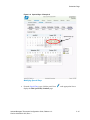
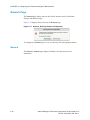
Network Page
The Network page displays tabs for the General, Remote Access, Notification
Settings, and Statistics pages.
Figure 2-17 displays when you access the Network page.
Figure 2-17
Network - Warning: Network Configuration
To configure the Network page or view as read only, click the appropriate button.
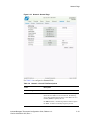
General
The Network - General page displays IP address, firewall, and web server
information.
2-32
Internet Managed Thermostat Configuration Guide, Release 1.0
Part No. 600-03001-350, Rev. 1
Beta Draft Confidential
Figure 2-18
Network Page
Network - General Page
Use Table 2-9 to configure the General fields.
Table 2-9
Network - General Field Descriptions
Field
Description
IP Addressing
IP Address Method
Select the method by which the thermostat receives the unique
Internet Protocol address for the local network. IP addressing
can be either automatically assigned via a local DHCP server or
manually (Static) assigned by the user.
DHCP (default) – IP addressing method is DHCP assigned.
Static – IP address is manually assigned by the user.
Internet Managed Thermostat Configuration Guide, Release 1.0
Part No. 600-03001-350, Rev. 1
2-33
Beta Draft Confidential
CHAPTER 2: Configuring the Thermostat Using the Web Interface
Table 2-9
Network - General Field Descriptions (Continued)
Field
Description
IP Address
Displays the unique Internet Protocol address either assigned
statically or by DHCP. (See IP Address Method.) (You must
click Submit after changing this parameter to invoke a software
reset to set the new value.)
A.B.C.D – Four field standard dot notation for IP address
designation.
Subnet Mask
Displays the IP subnet on which the thermostat IP address is
assigned.
Default Gateway
Displays the IP address of the router which acts as a gateway for
the thermostats to communicate to other devices in another
subnet.
DNS Server
Displays the IP address of the Domain Name Server.
MAC Address
Displays a factory assigned value installed in the thermostat
which uniquely identifies the thermostat on the local network for
transmitting and receiving network information.
The system displays the MAC address in the format of
00:19:88:AB:CD:EF for IMT350w and 00:11:49:AB:CD:EF for
IMT350c, where AB:CD:EF is a unique value for each
thermostat.
Web Server
HTTPS Port
Enter the IP port number of the Web server within the
thermostat.
xyz – Four digit (max) standard IP port number designation for
HTTP access. The default port number is 443.
Allow HTTP
HTTP Port
2-34
Disabled
Enabled
The default is port 80.
Internet Managed Thermostat Configuration Guide, Release 1.0
Part No. 600-03001-350, Rev. 1
Beta Draft Confidential
Network Page
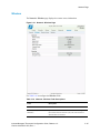
Wireless
The Network - Wireless page displays the remote access information.
Figure 2-19
Network - Wireless Page
Use Table 2-10 to configure the Wireless fields.
Table 2-10
Network - Wireless Field Descriptions
Field
Description
General
Network (SSID) (Service Set
IDentifier)
Specifies the name of the wireless network that is configured in
the wireless router/Access Point (AP). This is the network to
which the IMT is connected.
Internet Managed Thermostat Configuration Guide, Release 1.0
Part No. 600-03001-350, Rev. 1
2-35
Beta Draft Confidential
CHAPTER 2: Configuring the Thermostat Using the Web Interface
Table 2-10
Network - Wireless Field Descriptions (Continued)
Field
Description
Speed
Specifies the speed of the wireless connection that is negotiated
between the IMT and the wireless Access Point.
Signal Level
Displays the signal strength of the wireless connection in dBm.
-40dBm is a strong signal while -100dBm is a very weak signal
Noise Level
Indicates the amount of electrical activity in the 2.4Ghz band,
this can include activity from microwave ovens, other wireless
network and wireless devices like portable phones and
keyboards. Values greater than -80dBm (-79 to -10) are
considered noisy environments and may show connectivity
issues.
Peer Access Point
Displays the MAC address of the Access Point that the
thermostat is connected to. IT departments can use this to verify
the IMT is connected to the desired AP.
Transmit Power
Displays the value of how strong the current signal is on the
wireless chipset on the IMT.
Note: This can not be modified by the user.
Channel
Displays the value of the wireless channel the IMT is using to
communicate to the Access Point. The range is from 1-13.
Security
2-36
Security Mode
Determined by the wireless settings on the wireless Access
Point.
Encryption Type
Determined by the settings on the wireless Access Point.
Internet Managed Thermostat Configuration Guide, Release 1.0
Part No. 600-03001-350, Rev. 1
Beta Draft Confidential
Network Page
Remote Access
The Network - Remote Access page displays the remote access information.
Figure 2-20
Network - Remote Access Page
Use Table 2-11 to configure the Remote Access fields.
Table 2-11
Network - Remote Access Field Descriptions
Field
Description
Software Update Source
Server Address
Enter the IP address of the Remote Server for software updates.
Note that this field is pre-configured at the factory with
uem.proliphix.com.
Internet Managed Thermostat Configuration Guide, Release 1.0
Part No. 600-03001-350, Rev. 1
2-37
Beta Draft Confidential
CHAPTER 2: Configuring the Thermostat Using the Web Interface
Table 2-11
Network - Remote Access Field Descriptions (Continued)
Field
Description
Port Number
Enter the outgoing IP port number which is used to communicate
to the remote server. This field is pre-configured at the factory
with the IP port number of the Proliphix Web Server. Do not
change this value.
85 – (default) Port number of the remote server.
Remote Server Configuration
Remote Access
Controls whether the Remote Server service is enabled. Remote
access is the term used to describe the management and control
of the thermostat from networks outside the local subnet on
which the thermostat resides. Remote access provides the
thermostat with the ability to be controlled from across the
Internet (with the Proliphix UEM).
Disabled (default) – Remote Server function is disabled.
Enabled – The thermostat is enabled to participate with the
Proliphix UEM server.
Server Address
Displays the IP address or DNS name of the remote server.
Interval
Specifies the frequency of thermostat “calling home” to the
Proliphix server.
Last Attempt
Clicking Call Home forces the intercommunication between the
thermostat and the remote server.
Callhome Attempt State
mm.dd.yyyy – Date of last attempt to access the remote
server.
hh.mm.ss – Time since last attempt to access the remote
server.
Displays the status (Success or Fail) of last attempt to initiate the
communication to the remote server.
Push Server State
2-38
Last Success
Displays the date and time of last successful communication
with the remote server.
Last Change Upload
Displays the date and time the last change was made to the
thermostat configuration.
Last Observation Upload
Displays the date and time of the last upload of historical data to
the UEM server.
Internet Managed Thermostat Configuration Guide, Release 1.0
Part No. 600-03001-350, Rev. 1
Beta Draft Confidential
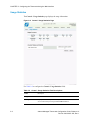
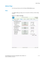
Network Page
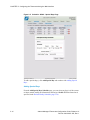
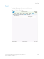
Statistics
The Network - Statistics page displays the network traffic information.
Figure 2-21
Network - Statistics Page
Internet Managed Thermostat Configuration Guide, Release 1.0
Part No. 600-03001-350, Rev. 1
2-39
Beta Draft Confidential
CHAPTER 2: Configuring the Thermostat Using the Web Interface
Admin Page
The Admin page displays tabs for the General, Date and Time, Password Settings,
Restart, and Software Update pages.
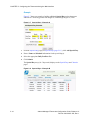
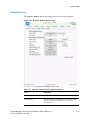
General
The Admin - General page displays the device name, serial number, LCD
information, for example.
Figure 2-22
2-40
Admin - General Page
Internet Managed Thermostat Configuration Guide, Release 1.0
Part No. 600-03001-350, Rev. 1
Beta Draft Confidential
Admin Page
Use Table 2-12 to configure the General fields.
Table 2-12
Admin - General Field Descriptions
Field
Description
Zone
Device Name
Enter a unique 15 character identifier for the thermostat. You can
use the thermostat location in this field (i.e. Main Lobby). This
identifier is known as the host name within the data network.
Thermostat
Serial Number
Displays an eight digit alpha-numeric thermostat serial number
(e.g. 8438F399).
Software Version
Displays the current software version.
Software Build Date
Displays the date and time the current version of software.
Hardware Revision
Displays the hardware revision.
LCD Settings
Backlight
Select the LCD backlight control.
Delay (default) – The backlight is illuminated when you
click a button and remains illuminated for 16 seconds after
the last button is clicked.
Always On – The backlight is enabled.
Always Off – The backlight is disabled from activation. A
low level ambient backlight remains visible.
Internet Managed Thermostat Configuration Guide, Release 1.0
Part No. 600-03001-350, Rev. 1
2-41
Beta Draft Confidential
CHAPTER 2: Configuring the Thermostat Using the Web Interface
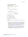
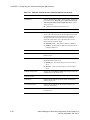
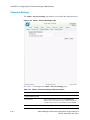
Date and Time
The Admin - Set Date and Time page displays the network time and time zone
information.
Figure 2-23
2-42
Admin - Date and Time Page
Internet Managed Thermostat Configuration Guide, Release 1.0
Part No. 600-03001-350, Rev. 1
Beta Draft Confidential
Admin Page
Use Table 2-13 to configure the Admin - Date and Time fields.
Table 2-13
Admin - Date and Time Field Descriptions
Field
Description
Thermostat Timezone
Timezone
Displays the current timezone.
Observe DST
Click to adjust the time for Daylight Savings Time.
Manually Set Date and Time
New Date
Enter a new date.
New Time
Enter a new time.
Use web browser date and time
Click to use configure date and time using browser date and
time.
Internet Managed Thermostat Configuration Guide, Release 1.0
Part No. 600-03001-350, Rev. 1
2-43
Beta Draft Confidential
CHAPTER 2: Configuring the Thermostat Using the Web Interface
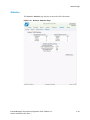
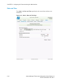
Password Settings
The Admin - Password Settings page enables you to modify the Admin password.
Figure 2-24
Admin - Password Settings Page
Use Table 2-14 to configure the Admin - Password Settings page.
Table 2-14
Admin - Password Settings Field Descriptions
Field
Description
Change Admin Password
2-44
New Password
Enter an alpha-numeric password for the Administrator
(admin) account. The password is case sensitive and limited to
15 alpha-numeric characters. The default password is admin.
Re-enter Password to Confirm
Re-enter your password.
Internet Managed Thermostat Configuration Guide, Release 1.0
Part No. 600-03001-350, Rev. 1
Beta Draft Confidential
Admin Page
Restart
The Admin - Restart page enables you to restart the thermostat.
Figure 2-25
Admin - Restart Page
Internet Managed Thermostat Configuration Guide, Release 1.0
Part No. 600-03001-350, Rev. 1
2-45
Beta Draft Confidential
CHAPTER 2: Configuring the Thermostat Using the Web Interface
Software Update
The Admin - Software Update page enables you to check for and download any
updates to the thermostat. Check the box and click Submit.
Figure 2-26
2-46
Admin - Software Update Page
Internet Managed Thermostat Configuration Guide, Release 1.0
Part No. 600-03001-350, Rev. 1
Beta Draft Confidential
Index
C
H
Calendar view 2-10
Configuring the thermostat
Heat pump
using the Web pages 2-1
settings for 2-26
HVAC state 2-5
D
M
Default weekly schedule 2-10
DHCP. See Dynamic Host Configuration Protocol 1-1
Dynamic Host Configuration Protocol 1-1
MAC address 2-34
P
E
Password
setting 2-44
External thermal sensors
settings 2-23
R
F
Remote management 1-2
Filter
set change reminder 2-19
Fuel burner
settings for 2-26
S
Special days 2-12
Subnet mask 2-34
G
Gateway address 2-34
T
Thermostat
accessing the initial HTML page 1-3
Internet Management Thermostat Configuration Guide, Release 1.0
Part No. 600-03001-350, Rev. 1
Index-1
Index
configuring using Web pages 2-1
connecting to local network 1-2
managing remotely 1-2
scheduling 2-8
Thermostat Management Interface 1-2
Index-2
Internet Management Thermostat Configuration Guide, Release 1.0
Part No. 600-03001-350, Rev. 1