1
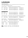
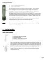
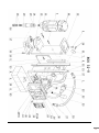
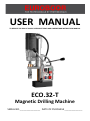
USER MANUAL
TO REDUCE THE RISK OF INJURY USER MUST READ AND UNDERSTAND INSTRUCTION MANUAL
ECO.32-T
Magnetic Drilling Machine
SERIAL NO._______________ DATE OF PURCHASE _____________
1 - Table of Contents
1
2
3
4
5
6
7
8
Table of Contents ……………………………………………………………………………………………………
Safety ……………………………………………………………………………………………………………………..
Before Use ………………………………………………………………………………………………………………
Items Included in Delivery ……………………………………………………………………………………….
The Hole Cutter
Hole Cutter Selection ...................................................................................................
Cooling/Lubrication ......................................................................................................
Tool Assembly
Hole Cutter Assembly ……………………………………………………………………………………...........
Drill Chuck Assembly ……………………………………………………………………………………............
Installation of 13mm Chuck by using Adaptor IBK.14 .................................................
Installation of 13mm Chuck directly on the motor unit ..............................................
The Magnetic Drilling Machine
The Magnetic Base ....................................................................................................
The Control Panel ......................................................................................................
Drilling .......................................................................................................................
Drilling with 32T..........................................................................................................
Tapping with 32T ........................................................................................................
Maintenance ................................…………………………………………………………………………..
Spareparts & Exploded View.........…………………………………………………………………….......
page
page
page
page
1
2
3
4
page 5
page 6
page
page
page
page
6
7
7
7
page 7
page 8
page 9
page 9
page 9
page 10
page 11
Read these directions and safety instructions
completely and attentively and carefully follow
these recommendations. All safety measures
must be observed at all times when using
magnetic drilling machines. Improper use and
carelessness increase the risk of accidents.
This is for your own safety.
Should you have any doubts about the use of this machine, please contact your supplier
2
2 - Safety
1. During any work on non-horizontal components, the machine must always be secured with the
supplied safety chain.
2. The magnetic drilling machine may only be used on a flat and clean foundation.
3. If the machine or the lead show signs of damage, the magnetic drilling machine must be switched
off immediately.
4. Wearing safety glasses, hearing protection and protective clothing is necessary.
5. Do not wear any loose clothing or jewellery that may get entangled in the moving parts of the
magnetic drilling machine.
6. Use only accessories or parts that are recommended by Euroboor.
7. During drill operations, the hole cutter must be cooled and lubricated with good quality cutting or
lubrication oil.
8. The motor must be switched off when tightening the machine with the safety chain.
9. When changing a hole cutter, the magnetic drilling machine must be disconnected from power
supply.
10. Clean the area around the machine regularly. Keep the bottom of the magnet and keep it clean and
dry.
11. Regularly inspect whether all screws, nuts and bolts are tight.
12. Remove the burr or slug from the hole cutter after each hole. Caution, the part may be hot!
13. Before using the machine make sure it is connected to the correct voltage and that all grips and
parts are tightly attached.
14. When using the drill on non-horizontal surfaces, you must use a drilling compound or cutting paste.
15. Do not use oil because the oil can drip into the motor unit.
When using this machine, you MUST wear ear and eye protection.
Euroboor has included these articles as standard accessories for your own
safety. Do NOT touch the drill when it is running. Always follow the
recommendations for personal protection when using this tool.
3
Before use
Euroboor magnet drilling machines are specially designed for drilling holes is steel, possibly expanded by
the possibility of tapping/reaming/countersinking (depending on model). Euroboor magnetic drilling
machines may not be adapted and/or used for applications other than those they were designed for,
including driving other machines.
Make sure that you can oversee the entire work areas from where you are operating this machine. Use
barriers to keep others away. Do not use the machine in places subject to hazard of explosion- electrical
tools produce sparks which may ignite flammable materials or gasses. To prevent electrical shocks, do not
use the machine in moist or wet conditions or environments. Always operate this tool using both hands.
Make sure the work piece is always clamped down safety.
This magnetic drilling machine is equipped with a lead and plug approved for the country or region it is to
be used in. The yellow-green wire in the lead is the earth wire. Never connect this to a pole under voltage.
All Euroboor magnetic drilling machines are manufactured to use with AC current and not suitable to work
on DC current. Make sure the magnetic drilling machine is connected to a stable power supply. Euroboor
do not recommend the use of a generator or other mobile power supply for power supply. Euroboor does
not recommend the use of extension cables. If there is no other way, use good quality cables and keep
extension cables as short as possible. Be aware that long power leads can cause less current.
3 - Items Included in Delivery
Magnetic Drilling Machine
Carrying Case
Drill Chuck 13mm
Tap Collets M10-M12-M14-M16
Allen Key 2.5
Allen Key 3
Allen Key 4
Allen Key 5
Wrench 8
YES
YES
NO
YES
YES
YES
YES
YES
YES
Pilot Pin
Morse Taper
Morse Taper Ejector Pin
Manual
Safety Chain
Drilling Oil
Safety Ear Protection
Safety Glasses
Safety Gloves
YES
NO
NO
YES
YES
YES
YES
YES
YES
4
4 - The Hole Cutter
Hole Cutter selection
There are many different types of steel. It is not possible to drill all these types of steel with 1 type of
cutter. Euroboor recommended the following :
Euroboor+ HSS Series
For drilling holes in general 37/52 steel and aluminium
HCS
12 mm - 130 mm
Hole cutters with cutting depth 30 mm
increasing by 1 mm
HCL
12 mm - 130 mm
Hole cutters with cutting depth 55 mm
increasing by 1 mm
HCY
20 mm - 50 mm
Hole cutters with cutting depth 75 mm
increasing by 1 mm
HCX
20 mm - 50 mm
Hole cutters with cutting depth 100 mm increasing by 1 mm
Also available in inch sizes:
HCS
7/16” - 5”
HCL
7/16” - 5”
HCY
3/4” - 2 1/16”
HCX
3/4” - 2 1/16”
Hole cutters with cutting depth 30 mm
Hole cutters with cutting depth 55 mm
Hole cutters with cutting depth 75 mm
Hole cutters with cutting depth 100 mm
increasing by 1/16”
increasing by 1/16”
increasing by 1/16”
increasing by 1/16”
Euroboor Cobalt Series For processing steel, stainless steel and other high-quality steel alloy types
IBS
12 mm - 130 mm
Hole cutters with cutting depth 30 mm
increasing by 1 mm
IBL
13 mm - 130 mm
Hole cutters with cutting depth 55 mm
increasing by 1 mm
Euroboor TCT Series
Tungsten Carbide Tipped. Cutters with hard metal teeth
HMS
14 mm - 50 mm
Hole cutters with cutting depth 35 mm
increasing by 1 mm
HML
14 mm - 130 mm
Hole cutters with cutting depth 50 mm
increasing by 1 mm
Euroboor TRC Series
With hard metal teeth, For drilling holes in rails
TRCS.190
19 mm
Hole cutter with cutting depth 35 mm
TRCS.300
30 mm
Hole cutter with cutting depth 35 mm
TRCS.330
33 mm
Hole cutter with cutting depth 35 mm
NOTE :
Hole cutters 12mm - 60mm have a 19,05 mm Weldon shank
Hole cutters 61mm - 130mm have a 31,75 mm Weldon shank
5
Cooling/Lubrication
1
2
Holes for cooling and lubrication oil
Fixing screws of spindle
Euroboor recommends the use of cooling and lubrication agents. Not only do these
assist in drilling but they will also lengthen the lifespan of your tools. One of the
advantages of the use of hole cutters is that cooling and lubrication agent scan be
supplied from the inside, so that the agents end up in the right place.
All magnetic drilling machines from Euroboor can be equipped with a automatic cooling
system which provides a guaranteed supply of the cooling and lubrication agents from
the inside. If your machine is not be equipped with an automatic coolant system it will
still be possible to cool from the inside.
Use the holes in the spindle (number 1 in picture) for this purpose by squirting the
cooling and lubrication agent into the drill spindle through them
NOTE :
For vertical or upside-down processing, Euroboor recommends the use of a drilling
compound or paste like IBP50/2.
5 - Tool Assembly
Hole Cutter Assembly
1 : Pilot Pin
2 : Center hole in shank of Hole Cutter
3 : Shank of Hole Cutter
4 : Groove or flatted surface for oil pass
5 : Flat surface for fixing Hole Cutter
Clean the inner wall and the shaft of the Hole Cutter to ensure proper oil supply. First
insert the Pilot Pin into the center hole of the Shank. After that you can slide the Hole
Cutter assembly into the spindle of your Magnetic Drilling Machine. After sliding the
Hole Cutter Assembly into type spindle, make sure the two flat surfaces (number 5 in
picture) are located exactly in front of the two fixing screws of your spindle (see
number 2 in picture of chapter 4-4-2). Tighten them both subsequently with the
included 4mm Allen Key.
6
Drill Chuck Assembly
The option of making our machines suitable for the use of standard spiral drills and other tools by using a
cylindrical shaft is an important characteristic of Euroboor magnetic drilling machines. Please see the
technical data for maximum capacity.
Installation of 13mm Chuck by using adapter IBK.14
The IBK.14 is a adaptor from 1/2"x20 UNF to 3/4" Weldon.
Attach a Drill Chuck (like Euroboor IBK.13) with internal 1/2"x20 UNF on the IBK.14 adaptor.
To attach the assembly into your Spindle, follow the instructions (with exception of the Pilot Pin) for
installation of a Hole Cutter. Adaptor IBK.14 can be used on most machines in our program.
Installation of 13mm Chuck directly on the motor unit
For the ECO.32, ECO.32T, ECO.40 and IBM.30/2 magnetic drilling machines it is possible to install a drill
Chuck directly to the shaft extending from the motor unit. For ECO.32T First remove the two Allen screws
on top of the spindle with the included Allen key no. 3. Remove the Spindle by using wrench 18 and 20. Fix
the extending motor shaft with wrench 18 and turn the spindle with wrench 20 anti-clockwise.
Take the spindle of the shaft and out of the triangular guide (Steady). Remove all the Allen screws below
the triangular guide by using the included Allen Key no. 5. Now can install the Drill Chuck with internal
1/2"x20 UNF tread on the extending shaft of the motor unit.
IMPORTANT : When reinstalling the spindle and the triangular guide (steady), you must ensure that the
triangular guide (steady) does not cause any friction or resistance to the spindle as it turns.
6 - The Magnetic Drilling Machine
The Magnetic base
Material of minimum 10mm thickness is required for the magnet to work the best.
The attachment force generated by the magnet depends on various factors.
- Thickness of the material the magnet is placed on
- Paint or coating of the material the magnet is placed on.
- Metal chips, oil or other dirt under the magnet.
If the LED indicator (see chapter 4-3-2) lights up GREEN, the magnet is generating sufficient attachment
force. If the LED indicator lights up RED, the magnet may not generating sufficient attachment force.
We would like to point out that this is only an indication and not a certainly that the magnet will not
release from the material. Euroboor accepts no liability ensuring from the magnet indicator not
functioning or functioning poorly.
7
Make sure that the magnet attaches tightly to the work piece before turning on the motor unit of the
magnetic drilling machine. Euroboor magnets have 2 coils; make sure that both coils are in contact with
the material. Do not connect any other machines to the electrical outlet the magnetic drilling machine is
plugged into, as it may result in the loss of magnetic force. Always use the safety chain included. Drilling
above your head is extremely dangerous and is not recommended. For the use of magnetic drilling
machines on pipes, not-flat or non-magnetic materials, we refer to our brochure or our website
www.euroboor.com where several vacuum tightening systems and pipe clamping systems are mentioned.
The Control Panel
The control panel on your magnetic drilling machine is designed for maximum operating facility and safety.
1 - The Magnet Switch:
This switch is used to switch the main power and also the
magnet On and Off. This switch is included on every
Euroboor magnetic drilling machine
2 - The On/Off Switch:
This switch is used to switch the motor unit On and Off and
is included on every Euroboor Magnetic Drilling Machine
3 - The Fuse holder with Fuse:
This Fuse holder is included on every Euroboor Magnetic
Drilling Machine and holds the fuse type : 5x20, F2A.
4 - The LED Indicator:
This LED indicator shows if the motorunit is powered.
5 - The L/R Switch:
This switch controls the direction of the motorunit.
6 - The Potentiometer:
This controls the running speed of the motorunit.
Note that a lower position will decrease the power of the motorunit.
8
Drilling
Now that you have read the explanatory information and safety recommendations above, you are ready to
actually start drilling. Follow these 10 steps for best drilling result :
1
2
3
4
5
6
7
8
9
10
Use the tip of the pilot pin to determine the center of the hole to be drilled.
Turn the magnet on and verify that the drill is in the right position and that the machine is
pushed tight against the work piece.`
If your machine is equipped with a auto coolant system, put open the valve to release the oil.
If your machine does not have a auto coolant system, fill the holes of the spindle with oil.
Turn the motor on at the highest setting and allow it to run at full speed.
Turn the arms to start drilling. Apply only a slight pressure when the hole cutter touch the
metal. Do not push the hole cutter with force into the metal.
Apply a regular pressure while drilling. The drilling performance does not improve by putting
more pressure on the tool. Too much pressure will overload the motor and your hole cutter
will be worn sooner. Let the cutter do the job and give it time to cut the metal !!!
Adjust the oil supply when necessary, if your drill does not have a auto coolant system, stop
drilling regularly, refill the holes of the spindle and continue drilling.
Apply less pressure when the drill cuts through the material.
Turn the arms to put the motor in highest position and turn off the motor unit.
Remove the burr, metal chips and clean the cutter and surface without getting injuries.
Caution : The metal piece drilled out can be sharp and very hot!!
Drilling with 32T
For most common sizes the electronic speed adjustment can be set at 100%. For sizes around 30mm the electronic
speed adjustment can be set a bit lower. Note that a lower gain does not only lower the rpm of the motorunit but
also its maximum power. If the machine do not have the power to drill then increase the gain of the electronic speed
adjustment
Tapping with 32T
First, drill the hole on the recommended size of the tap. Do not turn the magnet off to keep the machine
on its position.
Take the cutter out and use a tap collet (Euroboor TCM series) to fix the tap to the machine. These TCM
adapters exist in several DIN and ISO norms and are based on the shaft diameter of the tap that is used.
Use a low rpm to start tapping. When the machine comes to a stop, increase the electronic speed
adjustment till the motorunit slowly runs again. Stop the machine manually before the tap is completely
through the hole. Select the Reverse (Left) and let the tap run back slowly but also support the run back by
turning back the handles. Do not let your tap push back the motorunit by itself! If your tap have to make
the whole way through the material, then remove the tap out of the collet when the hole is completely
tapped.
!!! IMPORTANT !!!
When using your magnetic drilling machine non-horizontal or upside-down be aware
that no oil, drilling compound or metal chips can fall into the motor unit.
Euroboor accepts no responsibility for damage done to your machine
by such action under coverage of the warranty.
9
7 - Maintenance
Just as every magnetic drilling machine with moving parts, your Euroboor magnetic drilling machine also
needs regular maintenance service. A few recommendations follow :
-
Clean all dirt, dust, metal chips and burrs of your magnetic drilling machine
-
Regularly check the carbon brushes for wear
-
Replace any defective parts immediately. This prevents properly function parts from being damaged.
-
Adjust your guide regularly and make sure it is clean and greased. This prevents any movement from
being created and the spindle, triangular guide (steady) and guide parts from excessive wear or
damage. The guide can be adjusted by loosening the setting nut (#7 on spare part drawing) with
included wrench 8, tightening the setting screws (#5 on spare part drawing) with included Allen key
2.5 and tightening the setting nut (#7) again with included wrench 8. The adjustment is done well
when the motor unit can be turned to every possible position without falling down by its own weight.
-
Check the grease in the gearbox regularly and replace it if necessary. We recommend you to store
your machine on its side regularly so that the gear box grease can run back to where the gears are.
This is very important when you have used your machine non-horizontal or upside down.
Repair, modification and inspection of Euroboor Magnetic drilling machines must be done by a
Euroboor authorized dealer. The parts list will be helpful if presented with the machine to the
Euroboor dealer for service when requesting repair or other maintenance.
Euroboor machines are constantly being improved and modified to incorporate the latest
technological advancements. Accordingly, some parts (ie part numbers and/or design) may be
changed without prior notice. Also, due to Euroboor's continuing program of research and
development, the specifications of machines are subject to change without prior notice.
10
8 - Spareparts & Exploded View
1
2
3
4
5
6
7
8
9
10
11
12
13
14
15
16
17
18
19
20
21
22
23
24
25
26
27
28
29
30
31
32
33
34
35
36
37
38
39
40+41
42
43
44
45
51
52
53
54
55
56
57
58
59
020.0056
020.0106
020.0111
020.0096
020.0091
020.0051
032.0011
032.0016
020.0156
032.0026
020.0146
032.0041
020.0142
032T.0032
020.0121
020.0131
020.0145
020.0136
020.0176
020.0086
020.0084/4
020.0061
020.0077
020.0081
020.0066
032T.0046
020.0041
020.0031
020.0036
020.0182
PP.RSEU
032T.0003
PP.32TEU/2
100.0152
020.0037
020.0006
020.0016
020.0017
020.0011
032T.0058
032T.0061
032T.0201
032T.0202
032T.0101
032T.0102
032T.0009
032.0136
032.0141
032.0116
032.0156
032.0121
032.0191
032.0126
032.0221
032.0171
Frame
Screw SSM6x16
Washer M6
Setting Nut
Setting Screw
Magnet for 32T H=48mm
Slide
Rack
Screw SSM6x20
Motorholder
Screw SSM6x25
Top fixing plate 120mm
Steady
Spindle
Springset spindle
Circlip
Autocoolant Ring
Fixing Screw M8x8
Fixing Screw M6x6
Brass rail set (stick)
Pressing strip 4 holes
Capstan Hub assembly
End Plate
End Screw
Arm for Capstan
Motorcable 32T
Coupling nut motorcable
Coupling nut maincable
Main Cable
Screw+washer+nut
Rear plate
Panel screw long
Front plate
L/R Switch (push)
Cableclamp
On/Off switch
Fuse Holder
Fuse F2A
Magnet Switch
Potentiometer complete
LED indicator
Control Unit 220v
Control Unit 110v
Motorunit 220v
Motorunit 110v
Spacer
Screw for spring
Spring
Screw BK4,2x13
Screw BK3,9x60
Adaptor ring 22x0,5
Adaptor ring
Bearing (closed) 8x22x7
Bearing 8x22x7
Bearing 12x28x8
60
61
62
63
64
65
66
67
68
69
70
71
72
73
74
75
76
77
77.1
78
032.0186
032.0226
032.0201
032.0231
032.0131
032.0146
032T.0116
032T.0117
032T.0146
032T.0147
032.0111
032.0241
032.0206
032.0216
032.0106
032.0196
032.0161
032.0176
032.0166
032.0236
032.0237
032.0211
Spindle Gear
First Gear
Spindle Drive shaft
Axle
Adaptor ring Cap
Carbon brush set
Field 220v
Field 110v
Armature 220v
Armature 110v
End Cover
Housing
Gear Casing
Screw BK4,8x38
Screw BK4,8x50
Bearing 17x35x10
Baffle
Circlip 471/10
Circlip 472/28
Inner Gear Plate
Gasket
Casing Pin
11
12
Important notice :
Because of minor changes to our machines it is recommended to provide the framenumber of your
machine when ordering spareparts. This number can be found on front of machine at magnetic base and
frame. When you have any doubt when ordering spareparts, please contact your supplier before ordering.