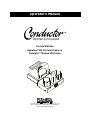
1
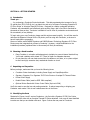
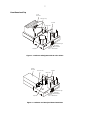
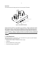
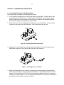
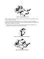
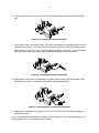
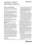
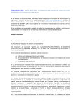
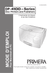
Operator’s Manual
For Use With the
Signature® III CD Color Printer or
Inscripta™ Thermal CD Printer
Two Carlson Parkway North • Plymouth, MN 55447-4446 U.S.A.
Phone: 1-800-797-2772 • 763-475-6676 • FAX: 763-475-6677
Internet: www.primeratechnology.com
2
3
© 2000 All rights reserved.
Notices: The information in this document is subject to change without notice. NO WARRANTY OF
ANY KIND IS MADE WITH REGARD TO THIS MATERIAL, INCLUDING, BUT NOT LIMITED TO, THE
IMPLIED WARRANTIES OF MERCHANTABILITY AND FITNESS FOR A PARTICULAR PURPOSE. No
liability is assumed for errors contained herein or for incidental or consequential damages in
connection with the furnishing, performance, or use of this material. This document contains
proprietary information that is protected by copyright. All rights are reserved. No part of this
document may be photocopied, reproduced, or translated into another language without prior
written consent.
Trademark Acknowledgments: Windows is a registered trademark of Microsoft Corporation. All
other trademarks are the property of their respective owners.
Printing History
Edition 1.0, # 082100
FCC Compliance Statement: This device complies with part 15 of the FCC rules. Operation is
subject to the following two conditions: (1) this device may not cause harmful interference, and (2)
this device must accept any interference received, including interference that may cause undesired
operation.
For Users in the United States: This equipment has been tested and found to comply with the
limits for a Class B digital device, pursuant to Part 15 of the FCC Rules. These limits are designed to
provide reasonable protection against harmful interference in a residential installation. This
equipment generates, uses, and can radiate radio frequency energy and, if not installed and used in
accordance with the instructions, may cause harmful interference to radio communications.
However, there is no guarantee that interference will not occur in a particular installation. If this
equipment does cause harmful interference to radio or television reception, which can be
determined by turning the equipment off and on, the user is encouraged to try to correct the
interference by one or more of the following measures:
•
Re-orient or relocate the receiving antenna.
•
Increase the separation between the equipment and receiver.
•
Connect the equipment into an outlet on a circuit different from that to which the receiver is
connected.
•
Consult the dealer or an experienced radio/TV technician for help.
Use of shielded cables is required to comply with the Class B limits of Part 15 of the FCC Rules. You
are cautioned that any changes or modifications not expressly approved in this manual could void
your authority to operate and/or obtain warranty service for this equipment.
4
For Users in Canada: This digital apparatus does not exceed the Class B limits for radio noise for
digital apparatus set out on the Radio Interference Regulations of the Canadian Department of
Communications. Le present appareil numerique n’emet pas de bruits radioelectriques depassant les
limites applicables aux appareils numeriques de la class B prescrites dans le Reglement sur le
brouillage radioelectrique edicte par le ministere des Communications du Canada.
CAUTION!
TO PREVENT FIRE OR SHOCK HAZARD, DO NOT EXPOSE THE UNIT TO RAIN OR MOISTURE. TO REDUCE
THE RISK OF ELECTRIC SHOCK, DO NOT REMOVE EXTERIOR PANELS. NO USER-SERVICEABLE PARTS
INSIDE. REFER SERVICING TO QUALIFIED SERVICE PERSONNEL. OPERATE THE UNIT WITH ONLY THE
PROPER ELECTRICAL SPECIFICATIONS AS LABELED ON THE PRINTER AND AC ADAPTER.
5
Table of Contents
SECTION 1: GETTING STARTED
A.
Introduction ........................................................................................................... 6
B.
Choosing a Good Location ....................................................................................... 6
C.
Unpacking and Inspection ....................................................................................... 6
D.
Identifying the Parts ............................................................................................... 6
E.
System Requirements ............................................................................................. 8
SECTION 2: HARDWARE AND CABLE SET-UP
A.
Connecting the Parts and Interface Cables ............................................................... 9
B.
Hardware Test........................................................................................................ 12
C.
Printing Your First Job............................................................................................. 13
SECTION 3: INTERPRETING THE LED STATUS LIGHTS
A.
Power LED.............................................................................................................. 14
B.
Pause LED .............................................................................................................. 14
SECTION 4: MAINTENANCE AND TROUBLESHOOTING
A.
Cleaning the Case ................................................................................................... 15
B.
Resetting the Robotics ............................................................................................ 15
C.
Technical Support ................................................................................................... 15
SECTION 5: TECHNICAL SPECIFICATIONS .................................................................. 16
INDEX .............................................................................................................................. 17
6
SECTION 1: GETTING STARTED
A. Introduction
Thank you . . .
. . . for purchasing a Conductor Printer Autoloader. This device automates the transport of up to
50 optical discs (CD-R, DVD-R, etc.) per batch into and out of a Primera Technology Signature III
CD Color Printer or Inscripta Thermal CD Printer. Designed for reliable, unattended operation,
Conductor will automatically and effortlessly print anything from a just a few CDs to hundreds or
thousands of discs per day. Conductor is suitable for use in office or production environments and
fits conveniently on any desktop.
To begin using your new Conductor, please read this entire manual carefully. You will also need to
reference the Operator’s Manual for the CD printer you’ll be using with Conductor, so be sure to
have it handy before proceeding.
Owners of earlier model FARGO Signature and FARGO/Primera Technology Signature II CD Color
Printers may also integrate their printers to Conductor. However, a slight modification to the
installation procedure (explained later in this manual) will likely be necessary.
B. Choosing a Good Location
•
Place Conductor in a location with adequate air circulation to prevent internal heat build up.
You’ll need a tabletop with at least 30” (76cm) of depth for adequate clearance.
•
Do not place the unit near heat sources such as radiators or air ducts, or in a place subject
to direct sun-light, excessive dust, mechanical vibration or shock.
C. Unpacking and Inspection
Before you begin, make sure that you have the following items:
•
Conductor Printer Autoloader, including Power Supply and Input/Output Bins
•
Signature, Signature II or Signature III CD Color Printer or Inscripta CD Thermal Printer
•
Printer Power Supply
•
Parallel Printer Cable (must be IEEE 1284 compliant)
•
Optional Printer Stand with Printer Control Cable (6-pin mini-DIN)
You’ll also want to save the box and packing materials. It makes transporting or shipping your
Conductor much easier if this is ever needed some time in the future.
D. Identifying the Parts
Illustrated in Figures 1 and 2 are two Conductors: the first with a Signature III CD Color Printer
attached and the other with an Inscripta Thermal CD Printer attached. Look over all items identified
to make sure that you are familiar with each. Figure 3 shows the rear panel of Conductor.
7
Front Panel and Top
Ink Jet
CD Printer
CD Printer Tray
Input Bin
Robotic Arm
LED Status Light
Pick Button
Control
Panel
Output Bin
Sequence Button
Pause Button
Figure 1: Conductor and Signature III CD Color Printer
Thermal
CD Printer
Input Bin
CD Printer Tray
Robotic Arm
LED Status Light
Pick Button
Output Bin
Control
Panel
Sequence Button
Pause Button
Figure 2: Conductor and Inscripta Thermal CD Printer
8
Rear Panel
This illustration shows the input ports found on the rear panel of Conductor:
Power Input Port
Printer Control Port
Control Port
SCSI Port
Figure 3: Rear Panel of Conductor
Please note that the SCSI port is not installed on your Conductor. Instead, a metal blank-off plate
has been put in its place. The Control Port is installed but not used. Both of these ports are for a
future upgrade to a fully automatic optical disc duplication and printing system called Composer™.
An upgrade to a Composer is accomplished by adding Windows®-based duplication software and a
CD-R or DVD-R drive. Contact your reseller or the factory for information on how to accomplish this
upgrade. Your printer autoloader configuration will use only the Printer Control Port and the Power
Input Port.
E. System Requirements
Before getting started, it is important for you to verify that the PC you plan to use with Conductor
meets these minimum system requirements:
•
Pentium® II/III or Celeron™ Processor, 233 MHz or higher
•
32MB RAM
•
Windows 95/98/NT/2000 operating system
•
Free hard drive space of at least 2MB
9
SECTION 2: HARDWARE AND CABLE SET-UP
A.
Connecting the Parts and Interface Cables
Follow these steps to integrate your autoloader and printer:
1. In the Conductor shipping box you will find the Input and Output Bins. Place the Bins in their
correct places as shown in Figure 1. Depending upon which printer you are using, you’ll see
that the locations for the Bins changes. Upon power-up, Conductor will automatically detect
which printer is being used by where you place the Bins.
2. Connect the Printer Control Cable that was included with your Printer Stand. Insert it into the
Conductor’s rear panel 6-pin mini-DIN socket. Don’t connect the other end yet.
Figure 4: Connecting the Printer Control Cable
3. Apply power to the Conductor by connecting the Power Supply cord to the Conductor’s rearpanel Power Input Port. Don’t plug the other end into a wall outlet yet.
Figure 5: Connecting Power to Conductor
4. Attach the Printer Stand to the Conductor by locating the connecting tabs and inserting them
into the appropriate slots on the rear panel of the Conductor. See illustration below for the slot
locations. For the Signature III CD Color Printer, the stand is attached so that it is centered on
Conductor as shown in Figure 6. For the Inscripta Thermal CD Printer, the printer is mounted on
the left side of the Conductor as shown in Figure 2.
10
2
1
Figure 6: Attaching the Printer Stand
Make sure that the Printer Control Cable is routed neatly out the back of the Printer Stand so that it
can be connected to your printer.
If you are using the Inscripta Thermal CD Printer, you will also need to install a Tray Support
Bracket to the top cabinet of the Conductor. Follow the instructions packed with the Thermal Printer
Printer Stand for installation of this bracket.
5. Place the printer on top of the Printer Stand, making sure that the silver locating pins are
inserted into the locating holes on the bottom of the printer.
Figure 7: Locating Holes on Bottom of Printer
Figure 8: Mounting Printer Onto Stand
11
6. Connect the other end of the Printer Control Cable to the printer’s rear-panel 6-pin mini-DIN
port.
Figure 9: Connecting the Printer Control Cable
7. Connect both ends of the Parallel Cable. One end is connected to the Parallel Input Port on the
rear panel of the printer. The other end is connected to your PC’s Parallel Printer Output Port.
Be sure that your PC’s LPT1 port (or other parallel port) is set to ECP mode. If you don’t know
how to do this, consult your printer and PC technical manuals for more information.
Figure 10: Connecting the Printer Parallel Cable
8. Apply power to the printer by connecting the printer’s Power Supply cord to the printer’s rearpanel Power Input Port. Connect the other end to a suitable wall outlet.
Figure 11: Connecting Power to Signature III CD Printer
9. Apply power to Conductor by plugging in the cord on the other side of the Power Adapter to a
suitable wall outlet.
You’ve now completed the assembly and cabling of the Conductor. Go on to the next section for a
quick Hardware Test. You’ll be printing discs shortly!
12
B. Hardware Test
1. Load the Input Bin with at least 4-5 CDs and place the output bin in the proper location.
Figure 12: Loading CDs
2. Press the Sequence Button on Conductor’s front panel. The Robotic Arm will swing over to and
above the Input Bin.
3. Press the Pick Button. The Robotic Arm will pick up a CD.
4. Press the Sequence Button again. The Robotic Arm will swing in front of the printer.
5. Open the printer’s tray. On Signature III, this is the button middle button on top of the unit.
On Inscripta, this is the button at the bottom right side of the unit.
Figure 13: Tray Open Button on Signature III
6. Press the Pick Button. The CD will drop into the printer tray. If it does not drop perfectly into
place, you will need to adjust the printer stand’s Mounting Plate. This is accomplished by
loosening the three Phillips-head adjusting screws and moving the printer slightly in one
direction or another until the disc is dropped perfectly into the printer’s tray. You can repeatedly
press the Pick button to test your alignment. Or, press and hold the Pick button for 5 seconds,
then release it, and the disc will be positioned about 5 millimeters above the tray for easy visual
alignment.
Figure 14: Adjusting the Printer Stand
13
NOTE TO USERS OF SIGNATURE AND SIGNATURE II CD COLOR PRINTERS:
Due to a slight difference in CD Tray length between these earlier models, the instructions for
adjusting the printer on the Printer Stand may not lead you to a perfect alignment.
As an alternative to the procedure explained in the printer stand instruction sheet, simply
remove the adjustable printer stand top plate. Align the printer and allow it to sit on the stand
without the aid of the Locating Pins. Of course, you’ll need to be careful not to bump the
printer. If you do, the alignment will need to be reset.
7. Press the Pick Button again. The CD will be picked up by the Robotic Arm.
8. Press the Sequence Button. The Robotic Arm will swing over to and above the Output Bin.
9. Press the Pick Button. The CD drops into the Output Bin.
10. Press the Sequence Button again. The Robotic Arm returns to a position above the Input Bin.
11. Press the Pause and Pick Buttons together at the same time. This will reset the Conductor.
You have completed the test procedure and are now ready to start your first print job!
C. Printing Your First Job
Operation is really very simple: just print to your printer as you normally would as if no autoloader
were installed. Specify the quantity you wish to print, load discs, and Conductor will automatically
pick your discs from the Input Bin, feed them into the printer, print each disc, and transport finished
discs to the Output Bin. Here are a few other steps you’ll want to review before starting your first
print job:
1. Install the printer driver software on your PC according to the instructions in the printer
Operator’s Manual.
2. Design your text, graphics, and photos in any popular graphics software such as CorelDRAW®,
Adobe® Illustrator® or any other Windows-based program. The printer also comes with an
excellent disc graphics editing program called SureThing™ First Edition.
3. In the printer driver software for the printer you’re using (found under Start:Settings:Printers),
check under Properties:Media that the Manual Load is checked and the Manual Unload is
unchecked. This is VERY important – if these settings are not correct, your autoloader will not
autoload!
4. Print a job to the printer as you normally would, requesting the number of copies you desire.
That’s it! You should now be successfully printing and transporting up to 50 discs per batch –
automatically!
14
SECTION 3: INTERPRETING THE LED STATUS LIGHTS
The LED Status Lights, located on Conductor’s front panel, can tell you a lot about what is
happening at any given moment with the operation of the autoloader. To accurately interpret what
is meant when the lights are on, off or flashing, refer to the following chart:
A. Power LED
Status
Condition
Off
No Power. Plug in Power Adapter.
On Solid
Power is ON. This is Conductor’s normal “waiting” mode.
Flashing
Power is ON, but an error condition exists:
a. Didn’t pick up a disc
b. Dropped a disc
c. Discs out
d. Robotic arm stalled; probably hit something while moving. Press
any button on Control Panel to re-try.
B. Pause LED
Status
Condition
Off
Normal “waiting” mode
On Solid
Conductor is paused.
Flashing
Conductor is busy; i.e. motors are running, printer is printing, etc.
15
SECTION 4: MAINTENANCE AND TROUBLESHOOTING
Conductor is designed to operate for extended periods of time with very little attention. In fact, no
regular maintenance is recommended other than cleaning the outside case.
IMPORTANT:
Do NOT attempt to oil or grease the Duplicator’s Robotic Arm shaft or other components. You will
likely cause more harm than good! Any moving parts are designed to be run for the life of the
machine with no additional lubrication required.
A.
Cleaning The Case
Use a clean, white rag with a small amount of water or isopropyl alcohol to clean the Duplicator and
printer’s outside cases and CD trays. Stronger cleaning solutions are NOT recommended because
they may damage the paint and plastic materials from which the parts are manufactured. Always
disconnect your Conductor and printer power cords before cleaning. Resume operation only after
the surfaces are completely dry.
B. Resetting the Robotics
If you find yourself in a situation where the robotics are not responding properly, you may need to
do a system reset. A typical cause may be when you stop a job out of sequence. To do so, press
the Pause and Pick buttons at the same time.
C. Technical Support
If you have difficulties in operating your Conductor, the set-up and testing procedures in this manual
should, in most cases, solve the problem. If you still have difficulty, contact the technical support
number listed on the insert included in the supply pack that came with your product.
16
SECTION 5: TECHNICAL SPECIFICATIONS
Model
Conductor Printer Autoloader
Robotics
Controlled by Primera Technology Signature, Signature II or
Signature III CD Color Printers or Inscripta Thermal CD Printer
Minimum System
Pentium II/III or Celeron Processor (or equivalent) at 233 MHz or
higher, 32MB RAM, one free ECP parallel printer port, 2MB available
hard drive space
Disc Capacity
50 disc input, 50 disc output
Operating Systems
Windows 95/98/NT and Windows 2000
Power Requirement
100-240 VAC, 50/60 Hz, 60 watts
Weight
8.9 lbs. (4.04 kg)
Dimensions
16.625”W x 10”H x 10.125”D (422mmW x 254mmH x 257mmD)
Certifications
Emissions: FCC Class B, CE
Safety: TUV-GS, cTUVus, CE
Warranty
One year return-to-depot
17
INDEX
Bins
Input .....................................................................................................................7, 9, 12, 13
Output...................................................................................................................7, 9, 12, 13
Buttons
Pause ......................................................................................................................13, 14, 15
Pick .........................................................................................................................12, 13, 15
Sequence............................................................................................................................ 12
Cables
6-Pin mini-DIN ............................................................................................................ 6, 9, 11
Connections, Rear Panel ............................................................................................................... 8
Controls, Front Panel .................................................................................................................... 7
Hardware Testing ................................................................................................................. 12, 13
Identifying the Parts ..................................................................................................................... 6
LED Status Lights ....................................................................................................................... 14
Locating Holes, Printer................................................................................................................ 10
Location....................................................................................................................................... 6
Maintenance .............................................................................................................................. 15
Parallel Interface
Cable.................................................................................................................................. 11
ECP Mode ........................................................................................................................... 11
Ports
Printer Control .................................................................................................................. 8, 9
Power Input...................................................................................................................... 8, 9
Printer Driver Software ............................................................................................................... 13
Printers
Inscripta Thermal CD Printer...............................................................................6, 7, 9, 10, 16
Signature I and II ..................................................................................................... 6, 12, 16
Signature III ................................................................................................ 6, 7, 9, 11, 12, 16
Resetting the Robotics................................................................................................................ 15
Specifications ............................................................................................................................. 16
Stands, Printer ....................................................................................................................... 9, 10
System Requirements................................................................................................................... 8
18
Tech Support ............................................................................................................................. 15
Tray Support Bracket.................................................................................................................. 10
Unpacking.................................................................................................................................... 6
Printed in the United States of America
P/N 082100-510148