1
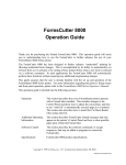
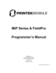
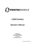
PRINTEK ITX INTERFACE
INTRODUCTION
The Printek ITX Interface option for the FormsPro 4300, FormsPro 4500, and FormsPro 4503 printers
provides a twinaxial interface which allows the IBM AS/400 or System 3X to fully utilize the printer’s
graphics capabilities by emulating an IBM 4224 IPDS printer. An industry standard parallel interface and
an RS-232C interface are also provided for ASCII applications. This interface also includes the optional
Printer Buffer Expansion.
This document includes a brief introduction to IPDS. Also included is detailed installation instructions,
configuration switch descriptions, trouble shooting tips for twinaxial installations, and instructions on
how to select the different form setups using the IBM drawer selection.
INTRODUCTION TO IPDS
The Intelligent Printer Data Stream is a page description language defined by IBM as a structured
field data stream for managing and controlling printer processes. IPDS allows a logical page, as
set up by the host system, to contain an unlimited variety of different types of data including high
quality text, raster images, bar codes, and vector graphs.
The IPDS data is handled as data towers. These data towers include Text, IM Image, IO Image,
Graphics, and Bar Code. Each of these towers includes a subset of commands for handling the
different data in each.
With the IPDS data stream, the data in these towers can come from different sources or programs
on the host system and be merged at the printer. These sources can be Advanced Function
Printing Utilities (AFP) or simple text processors. One example of this application would be
printing an invoice that would contain a bar code, expanded text, and graphic data along with
standard 10 cpi text. This task would be accomplished in two steps.
1. An overlay would be created on the host system using the AFP Utilities. This overlay
would call on a page segment (or graphic object) for the company name with address and
logo, vector fonts for expanded type, printer fonts for those fonts available in the printer,
bar code creation based on changeable data pulled from the host database, and lines and
boxes created using the overlay utility. See figure 1 for an example overlay.
2. The changeable data would be used from the database record as it is printed from the
application program. This data could include text and numbers for use in bar code creation.
When this data is printed the application program would specify a printer definition file to
use as the formatting for the print file. When the data is sent to the printer, the changeable
data is printed first and then followed by the overlay containing the form. See figure 2 for
an example of the completed form.
Completed Form
Figure 2
Form Overlay
Figure 1
Printek ITX Interface
Page 2
INSTALLATION
The following figure shows the location of the configuration switches, the address switch, and the
connectors as they are found on the Printek ITX interface on the back of the printer.
The Printek ITX Interface
Figure 3
To connect the printer to a host computer(s), perform the steps in the appropriate section(s)
below.
Connecting the Printer to an AS/400 or System 3x Computer
1. Make sure the printer’s power switch is “OFF”.
2. Plug the supplied “Smart-T” into the connector labeled “IPDS” on the back of the printer
and tighten the mounting screws.
3. Connect a twinax cable from the device up cable (closer to the host computer) to one side
of the Smart-T.
4. Connect a twinax cable from the other side of the Smart-T to the next device down cable
(farther from the host computer). If there is no device down cable, the Smart-T will
automatically provide the cable termination.
5. Select the device address (0-6) for the printer by rotating the knob on the switch labeled
“ADDR” until the indicator on the side of the knob is next to the correct number.
6. Set the configuration switches for the proper configuration for your installation. The
switch assignments are shown below.
7. Connect the printer’s power cable and turn “ON” the printer’s power switch.
Printek ITX Interface
Page 3
Configuration Switch Assignments
SW1-1
Off*
On
Operating Mode
Run
Configuration Print / Structured Field Dump
SW1-4
Off*
Off
Off
Off
On
On
On
On
Off
Off
Off
Off
On
On
On
On
SW1-5
Off*
Off
Off
Off
Off
Off
Off
Off
On
On
On
On
On
On
On
On
SW1-3
Off*
Off
On
On
Off
Off
On
On
Off
Off
On
On
Off
Off
On
On
SW1-6
Off*
On
Multiplexer Timeout
Short - about 5 seconds
Long - about 30 seconds
SW1-7
Off*
On
Host Initiated Forms Change
Enabled
Disabled
SW1-2
Off*
On
Off
On
Off
On
Off
On
Off
On
Off
On
Off
On
Off
On
Default Character Set
English (U.S.)
Brazilian
Italian
Canadian Bilingual
Danish/Norwegian
Spanish Speaking
English (U.K.)
Portuguese
Austria/German
Japanese/English
Spanish
Japanese/Katakana
French
International #5
Belgian
Swiss Bilingual
Off = 0, On = 1
* Factory Default Setting
All undocumented switches are reserved for factory/future use and should be left in the “0” or
“Off” position.
Host Configuration
With the ITX interface installed, the printer will auto-configure as an IPDS device on the AS/400.
The device type on the host computer should be set to “*IPDS”. The device may be configured
as either “AFP*Yes” or “AFP*No”.
Printek ITX Interface
Page 4
Twinax/Parallel Port Arbitration
The twinax port and the parallel port may automatically switch back and forth after the delay
specified by the Multiplexer Timeout switch. Note that the use of this capability requires
planning and control on the part of the user and/or system administrator to assure that data from
the two ports cannot be “mixed” together.
When data is received from the twinax port (after the timeout) the interface will automatically
switch to Printek emulation and select the EBCDIC font. When data is received from the parallel
port, the interface will automatically switch to the default emulation specified in the Interface
menu and select the forms parameters for the current form as specified in the Forms menu.
Connecting the Printer to a Computer Using the Parallel I/O Port.
Refer to the Parallel Interface section of the Installation and Quick Setup chapter of the FormsPro
4000 Series Operator’s Manual. References to “CX/TX” in the setup menu will now be replaced
with “IPDS”.
Twinax/Parallel Port Arbitration
The parallel port and the twinax port may automatically switch back and forth after the delay
specified by the Multiplexer Timeout dip switch. Note that the use of this capability requires
planning and control on the part of the user and/or system administrator to assure that data from
the two ports cannot be “mixed” together.
When data is received from the twinax port (after the timeout) the interface will automatically
switch to Printek emulation and select the EBCDIC font. When data is received from the parallel
port, the interface will automatically switch to the default emulation specified in the Interface
menu and select the forms parameters for the current form as specified in the Forms menu.
Connecting the Printer to a Computer Using the Serial RS-232
Port.
Refer to the RS-232C Serial Interface section of the Installation and Quick Setup chapter of the
FormsPro 4000 Series Operator’s Manual.
Printek ITX Interface
Page 5
CHECKING THE TWINAX INSTALLATION
Check the Twinaxial Cabling.
To verify that the printer is cabled correctly, review the following items.
1. Verify that the printer has the correct address setting.
2. Verify that the address in the system configuration matches the address setting on the
printer.
3. Verify that the device type in the system configuration is 4224 IPDS
4. Verify that the cable to the device immediately up cable on the twinax line is correctly
connected. That is, if there is an up cable device, does the cable from that device originate
at the “OUT” connection.
5. Verify that the device immediately up cable is functioning properly.
6. Verify that the device immediately down cable is functioning properly.
7. Verify that the last device on the line is providing the proper line termination. Also make
sure that the last device on the line is the only device providing termination.
Printing a structured field dump
A structured field dump is useful for verifying the configuration of the interface and that the
internal communications between the interface and the printer electronics are functioning
properly. To cause this dump to happen, perform the following steps.
1. Turn the printer’s power switch “OFF”.
2. Set the Operating Mode switch (SW1-1) to “ON”.
3. Turn the printer’s power switch “ON”. A structured field dump will print as follows. The
first and second pages will show the current configuration of the interface (current switch
selections are indicated by “==>“) and beginning with the third page, the data actually
received from the host will be displayed.
Printek ITX Interface
Page 6
Beginning of first page...
Printek Ipds
Copyright 1994, 1995 by Creative Controllers, Inc.
Main Control Processor ROM: 4660 Revision Level: xx.xx.x
Ipds Graphics Processor ROM: 1668 Revision Level: xx.xx.x
Ipds Structured Field Dump - Twinax Line Address is 0
SW1-1
0
==> 1
Operating Mode
Run
Configuration Print / Structured Field Dump
SW1-5
==> 0
0
0
SW1-4
0
0
0
SW1-3
0
0
1
SW1-2
0
1
0
Page 1
Default Character Set
English (U.S.)
Brazilian
Italian
Beginning of third page...
Printek Ipds
Copyright 1994, 1995 by Creative Controllers, Inc.
Main Control Processor ROM: 4660 Revision Level: xx.xx.x
Ipds Graphics Processor ROM: 1668 Revision Level: xx.xx.x
Ipds Structured Field Dump - Twinax Line Address is 0
Page 1
00 07 D6 97 40 01
;..0p ..
00 0C D6 33 40 00 02 F6 00 00 00 01
;..0. ..6....
00 0A D6 33 40 00 03 F8 00 FE
;..0. ..8.Ú
Printek ITX Interface
Page 7