1
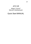
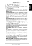
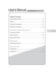
MPS 409 Setup Guide
This guide provides basic instructions for an experienced technician to install, set up, and
operate the Extron® Media Presentation Switcher, MPS 409. Where possible in the following
pages, line drawings are used to clarify steps discussed in the text. Installation and service
must be performed by authorized personnel only.
Installation
Step 1 — Disconnect Power
Remove power from the switcher and all other devices that will be connected.
MIC
VGA/YUV INPUTS
DVI INPUTS
2
1
EXEC
MODE
SINGLE
MODE
CONFIG
HDMI INPUTS
SEPARATE
2
1
2
1
VIDEO INPUTS
PROGRAM AUDIO
MUTE
MUTE
2
1
3
COMBINE DVI/HDMI
MPS 409
DIGITAL MEDIA PRESENTATION SWITCHER
Step 2 — Mount the Switcher
The MPS 409 is housed in a full rack width, 8.5 inch deep, 1U high metal enclosure. Select a
mounting location, then choose an appropriate mounting option and mount the switcher.
b
100-240V
c
0.4A MAX
1
2
VGA/YUV
OUTPUT
d
e
f
1
2
1
OUTPUT
1
1
2
l
Step 3 — Cable the Switcher
2
1
m
h
i
VIDEO
1
3
1
2
n
OUTPUT
o
2
p
OUTPUT
q
r
MI
PROGRAM
AUDIO
OUT
L
R
Sleeve ( )
(unbalanced)
c. For stereo input, connect up to nine audio sources to each of the unbalanced stereo audio
input groups; VGA/YUV (d), DVI (n), HDMI (g), and Video (i). See the 3.5 mm plug
connector diagram on the right for wiring.
Set switch 2 of the DIP switch bank
a microphone. If
R
R
OUTPUT
phantom power (+48V) is required, set switch 1 up (on).
For unbalanced audio, connect the
sleeve(s) to the ground contact.
DO NOT connect the sleeve(s) to the
negative (-) contacts.
Tip
Ring
Sleeve(s)
Tip
Ring
Tip
NO Ground Here
Sleeve(s)
Tip
NO Ground Here
Balanced Output
Unbalanced Output
MPS 409
MIC/LINE
PROGRAM
AUDIO
OUT
L
R
Tip
Unbalanced Mic Input
ON LINE
1
RS-232
Tx Rx
ON
g. (Optional) 2If theOUTPUT
switcher is connected to a computer or host
2
controller for remote control, connect
the host RS-232 cable to the
3-pin captive screw connector on the rear of the switcher (see the
figure at right).
(5 mm)
MAX.
Sleeve
LEVEL
+48V
MIC/LINE
AUDIO
L
R
OUTPUT
down
(off) for
R
CAUTION
AUDIO
L
R
f.HDMI
(Optional) Connect a microphone
to the rearVIDEO
Mic/Line connector
1
1
2
1
3
(see the figure
at right).
Refer to the microphone user
guide
forOUTPUT
L
L
L
3 proper wiring and phantom power requirements.
s
3.5 mm Stereo Plug Connector
b. Connect the VGA/YUV output (c), DVI output (m), HDMI output (p), and video (r) output
from the switcher to the appropriate display inputs.
e. Connect an audio amplifier to the Program Audio Output connectors.
See the connector diagram on the right for proper wiring.
R
Tip (L+)
Ring
(R+)
RCA Connector
2
OUTPUT
L
2
a. Attach up to two VGA/YUV (b), two DVI (l), three HDMI (f), and two composite video (h)
Sleeve ( )
input devices to the switcher.
d. For unbalanced stereo output, connect an output device to each of the
output groups; VGA/YUV (e), DVI (o), HDMI (q), and Video (s).
See the 3.5 mm plug connector diagram on the right for wiring.
R
R
OUTPUT
Tip (+)
Make certain the MPS 409, all sources, and displays are powered off. Run all audio, video,
communication and power cables for operation.
1
2
L
L
3
OUTPUT
OUTPUT
DVI-D
50/60 Hz
g
HDMI
2
OFF MIC
Tip
Ring
Sleeve
Balanced Mic Input
Tx Rx
(5 mm)
MAX.
Do not tin
the wires!
RS-232
Device
Transmit (Tx)
Receive (Rx)
Ground ( _ )
Bidirectional
Transmit (Tx)
Receive (Rx)
Ground ( _ )
1
LEV
+
MIC/LIN
MPS 409 Setup Guide (Continued)
Setup and Operation — Video Switching
The MPS switcher can be connected to as many as nine input devices simultaneously and operate in one of four switching modes:
single (the default), separate, single combined, or separate combined. To view the current mode, press and hold the Mode button
(VGA/YUV input #1). The associated mode LEDs (single, separate, single+combined, or separate+combined) will light.
Single Switcher Mode
Single switcher mode emulates one switcher with 9 inputs (9x1). Only one input
can be selected at a time, indicated by a single lit LED on the front panel input
selections. The selected video input will output on the associated group output
only while the audio is output on the group output and Program Audio Output.
To enable single switcher mode:
Press and hold the Mode button (VGA/YUV Input #1) for three seconds, then press
and release the Single button (VGA/YUV Input #2). The associated LED indicates
if single switcher mode is on (when lit) or off. When the Mode button is released,
EXEC
the LED resumes input indication.
MODE
Single Switcher Mode
VGA/YUV INPUTS
MODE
CONFIG
In the example below, HDMI input #2 is selected. Only the HDMI output is active.
HDMI audio, indicated by the flashing LED, is routed to both the group output and
Program Audio Output.
MIC
VGA/YUV INPUTS
MODE
DVI INPUTS
2
1
EXEC
CONFIG
MODE
SINGLE
HDMI INPUTS
SEPARATE
VIDEO INPUTS
2
1
2
1
2
1
3
DVI INPUTS
2
1
SINGLE
SEPARATE
HDMI INPUTS
2
1
2
1
COMBINE DVI/HDMI
Press and release
Single Mode
Press and Hold
for three seconds
PROGRAM AUDIO
MUTE
MUTE
COMBINE DVI/HDMI
MPS 409
DIGITAL MEDIA PRESENTATION SWITCHER
Single Switcher Mode
Separate Switcher Mode
Separate switcher mode allows the four groups of inputs (DVI, HDMI, VGA, and
composite video) to be used individually. Each group has an independent output
creating four independent switchers. Up to four inputs can be selected at one
time, one in each group, indicated by four lit LEDs. The audio and video of the
selected input group outputs only on the associated group output. Audio from the
last input selection also goes to the Program Audio Output. Of the four selected
inputs, the audio input routed to the Program Audio Output is indicated by the
blinking input LED.
Enable Separate Switcher Mode
To enable separate switcher mode:
Press and hold the Mode button (VGA/YUV Input #1) for three seconds, then press
and release the Separate (DVI input #1) button. The associated LED indicates ifEXEC
separate switcher mode is on (when lit) or off. When the Mode button is released,
MODE
the LED resumes input indication.
VGA/YUV INPUTS
MODE
CONFIG
In the example below, VGA/YUV input #2, DVI input #1, HDMI input #3 and
Video input #2 are selected. All four group outputs are active with their respective
AV input signals on them. The audio of DVI input #1 is also routed to the Program
Audio Output, indicated by the flashing LED.
MODE
CONFIG
MODE
DVI INPUTS
2
1
SINGLE
1
SEPARATE
HDMI INPUTS
2
1
2
VIDEO INPUTS
3
1
2
MUTE
SINGLE
Press and Hold
for three seconds
MIC
VGA/YUV INPUTS
EXEC
DVI INPUTS
2
1
1
SEPARATE
HDMI INPUTS
2
1
2
COMBINE DVI/HDMI
Press and release
Separate Mode
PROGRAM AUDIO
MUTE
COMBINE DVI/HDMI
MPS 409
DIGITAL MEDIA PRESENTATION SWITCHER
Separate Switcher Mode
Combined HDMI/DVI Mode
Combined mode allows the MPS 409 to function as a 5x1 HDMI/DVI switcher.
This is accomplished by switching a selected DVI or HDMI input to the HDMI video
output, deactivating the video output.
In single-combine mode, the front panel input selection LEDs operate the same
as when in single switcher mode (a single lit LED indicates the current input
selection).
2
MPS 409 Setup Guide (Continued)
In separate-combine mode, only one input selection is allowed from the
HDMI/DVI groups along with a single input selection from the VGA/YUV group
and another from the Video group. So there will only be three front panel input
LEDs lit in combined mode rather than four when in separate switcher mode.
To enable combined switcher mode:
Combined Switcher Mode
VGA/YUV INPUTS
Press and hold the Mode button (VGA/YUV Input #1) for three seconds, then
press and release the Combine DVI/HDMI button (DVI input #2). The Combine
DVI/HDMI button LED indicates if combined switcher mode is on (when lit)
or off. The Single and Separate button LEDs indicates whether it is in single
switcher mode or separate switcher mode. When the Mode button is released,
the LED resumes input indication.
MODE
DVI INPUTS
2
1
EXEC
MODE
CONFIG
SINGLE
1
SEPARATE
Press and Hold
for three seconds
HDMI INPUTS
2
1
VIDEO INP
2
3
1
COMBINE DVI/HDMI
Press and release
Combine DVI/HDME
Setup and Operation — Optimizing the Audio
For optimal audio quality, the audio input levels can be adjusted individually. In addition, the microphone
and program output levels can be adjusted separately using the front panel controls. Program output and
microphone levels are independent from each other. Muting program audio does not mute the microphone
input.
Setting the Input Audio Level
1. Simultaneously press and hold the Program Audio Mute and MIC Mute
buttons until the two mute LEDs flash three times, then release both
buttons.
VGA/YUV INPUTS
DVI INPUTS
a Press and hold
for 3 seconds
MIC
HDMI INPUTS
VIDEO INPUTS
2. Press a Video Input button for the audio to be adjusted (video input #1
is shown). If an input button is not pressed, the switcher times out and
exits audio level adjustment mode.
MODE
2
1
EXEC
SINGLE
MODE
CONFIG
1
2
1
2
3
2
1
PROGRAM AUDIO
MUTE
MUTE
COMBINE DVI/HDMI
SEPARATE
MPS 409
DIGITAL MEDIA PRESENTATION SWITCHER
3. In audio adjustment mode, when an input button is pressed, the front
b Press input to
panel input LEDs indicate the current gain/attenuation setting. Factory
select
default is 0 dB (all LEDs off). Rotate the Program Audio volume knob
clockwise to increase and counterclockwise to decrease the audio level. The
front panel LEDs display the level setting as the knob is adjusted (see
Audio Gain/Attenuation Adjustments in the MPS 409 User Guide).
c Adjust input
level
4. Once the desired level is achieved, to adjust another input, select it within
three seconds. If audio adjustments are complete, to exit the gain/attenuation
mode:
a. Do not press any front panel buttons for at least three seconds, or
b. Press the Program Audio Mute and MIC Mute buttons.
At any time during the adjustments, if the front panel buttons are not pressed or
the program knob is not rotated within three seconds, the switcher times out and
the gain/attenuation mode is exited.
Setting the Program Output Audio Level
1. Turn on all equipment and select an input with an audio signal present.MIC
I INPUTS
2
COMBINE DVI/HDMI
PROGRAM AUDIO
INPUTS
VIDEO INPUTS
2. Turn on HDMI
program
audio by pressing the
Program Audio Mute button
(the LED
MUTE
2
1
2
1
3
goes out).
MUTE
3. Using the Program Audio volume control (right), adjust the volume of the
audio amplifier connected to the Program Audio Out connector to achieve
the desired sound level.
MPS 409
DIGITAL MEDIA PRESENTATION SWITCHER
Setting the Microphone Level
1. Turn on all equipment and select an input with an audio signal present.
2. If the program audio output level has not been adjusted, do so before setting
DVI INPUTS
HDMI INPUTS
VIDEO INPUTS
the microphone
level.
MIC
VGA/YUV INPUTS
1
MODE
2
1
2
1
2
3
3. If phantom power is required for the microphone, be certain it is on.
1
2
MUTE
PROGRAM AUDIO
MUTE
4. Turn on the microphone by pressing the MIC Mute button (the LED goes out).
SINGLE
SEPARATE
COMBINE DVI/HDMI
5. Talk into the microphone in a normal voice and adjust the Mic volume knob
(right) to the desired sound level.
DIGITAL MEDIA PRES
3
MPS 409 Setup Guide (Continued)
Setting the Microphone Talk-Over Threshold
Microphone threshold (the volume where vocal audio is detected) and the program audio level during talkover are adjustable via SIS
commands. See Audio Adjustments in the MPS 409 User Guide for additional SIS commands.
1. Speak into the microphone in a normal voice. The main program audio level should drop moderately. If not, adjust the microphone
threshold level.
2. Stop speaking into the microphone. Main program audio should recover to its previous level after approximately four seconds. If
not, adjust the microphone threshold level.
3. If the program audio during talkover is too loud, or too soft, adjust the program audio level.
Mic talk-over threshold
Display talk-over threshold
X* * 2 #
Thr X* ]
Shows the mic threshold
number. X* = 0 through 15,
default = 8.
Decrement threshold
– * 2#
Thr X* ]
Decrements mic threshold one
step.
Increment threshold
+ * 2#
Thr X* ]
Increments mic threshold one
step.
View mic talk threshold
2#
X*
]
Extron USA - West
Headquarters
Extron USA - East
Extron Europe
Extron Asia
Extron Japan
Extron China
Extron Middle East
+800.633.9876
+800.633.9876
+800.3987.6673
+800.7339.8766
Inside Asia Only
+81.3.3511.7655
+81.3.3511.7656 FAX
+400.833.1568
Inside Europe Only
+971.4.2991800
+971.4.2991880 FAX
+1.919.863.1794
+1.919.863.1797 FAX
+31.33.453.4040
+31.33.453.4050 FAX
+65.6383.4400
+65.6383.4664 FAX
Inside USA/Canada Only
+1.714.491.1500
+1.714.491.1517 FAX
Inside USA/Canada Only
© 2010 Extron Electronics All Rights Reserved.
Inside China Only
+86.21.3760.1568
+86.21.3760.1566 FAX
www.extron.com
68-1833-50
Rev. A
07 10
4