1
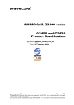
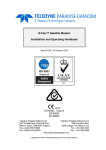
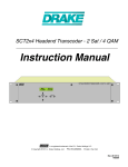
User Guide and Installation Manual HDME102 / HDME202 / HDME402 Single / Dual / Quad Input QAM Encoder / Modulator 1 HDME102/202/402 Manual V1.0 Table of Contents Safety Precautions..........................................................................................................................................3 Package Contents...........................................................................................................................................3 Product Description........................................................................................................................................4 Specifications.................................................................................................................................................5 Installation......................................................................................................................................................6 Hardware Installations and Connections........................................................................................................6 Connecting to the GUI Interface:...................................................................................................................7 Encoder Programming and Setup via GUI Interface:....................................................................................7 Overview Page of HDME Series Encoder.....................................................................................................8 GUI Login Password:.....................................................................................................................................8 Common Setup...............................................................................................................................................9 RF Setup ......................................................................................................................................................11 Encoder Setup..............................................................................................................................................11 Notes on Audio Source and Audio Output/Format:....................................................................................12 IP Streaming Setup.......................................................................................................................................13 Network Configuration................................................................................................................................14 Administration.............................................................................................................................................15 Saving your configuration files....................................................................................................................15 Front Panel LCD Encoder Menu Map.........................................................................................................16 Modulator Configuration via Front Panel LCD...........................................................................................17 EAS .............................................................................................................................................................23 2 HDME102/202/402 Manual V1.0 Safety Precautions The presence of this symbol is to alert the installer and user to the presence of uninsulated dangerous voltages within the product’s enclosure that may be of sufficient magnitude to produce a risk of electric shock. TO REDUCE THE RISK OF FIRE OR ELECTRIC SHOCK, DO NOT EXPOSE THIS DEVICE TO RAIN OR MOISTURE. DO NOT OPEN THE UNIT. REFER SERVICING TO QUALIFIED PERSONNEL ONLY. DO NOT apply power to the unit until all connections have been made, all components have been installed and all wiring has been properly terminated. DO NOT terminate, change or uninstall any wiring without first disconnecting the unit’s power adapter from the device. This device is supplied with the appropriately rated power supply. The use of any other power supply could cause damage and invalidate the manufacturer’s warranty. DO NOT connect the power cord to the device if the power cord is damaged. DO NOT cut the power cord. DO NOT plug the power cord into an AC outlet until all cables and connections to the device have been properly connected. The device should be installed in an environment consistent with its operating temperature specifications. Placement next to heating devices and ducts is to be avoided as doing so may cause damage. The device should not be placed in areas of high humidity. DO NOT cover any of the device’s ventilation openings. DO NOT cover or obstruct the device’s fan or fan openings. If the device has been in a cold environment allow it to warm to room temperature for at least 2 hours before connecting to an AC outlet. Package Contents This package contains: One HDME-102, or HDME-202, or HDME-402 QAM/IP Encoder / Modulator* One power cable One installation / configuration manual Inspect the package before starting installation to ensure there is no damage and all supplied contents are present. 3 HDME102/202/402 Manual V1.0 Product Description HDME Series of Encoder/Modulators simultaneously provide a QAM, ASI, and IP output stream* making it ideal for any Commercial RF or IP Networks. The high quality HD design allows for watching action packed movies and sports channels on any HDTV. Thor Digital's Series of Encoder/Modulators supports a variety of DTV standards: ATSC and DVB-C Annex B depending on your product. The Dolby® Digital Encoding capabilities, EAS, and AES-128 Encryption (Optional) capabilities rounds out the feature rich product series. The space saving design delivers up to 4 High Quality HD QAM/IP/ASI channels in a single 1RU space.. *Dolby is a trademark of Dolby Laboratories. Front panel LCD Display for easy installation High Resolution 1080i/1080p VCN Mode Composite, Component, and HDMI (unencrypted) inputs MPEG2 or MPEG4 (AVC) Video Output MER > 40dB Closed Captioning Support (708) +45dBmV Output Newly Added EAS Functionality Rack mountable 1RU height *Various optons are available at tme of order- check with your sales rep for a complete list of optons. Images of Front and Rear Panels of Single, Dual, and Quad versions 4 HDME102/202/402 Manual V1.0 Specifications INPUTS (VIDEO By Priority) HDMI Component Composite AUDIO Inputs Audio Input VIDEO Encoder Mode Video Resolutons AUDIO Encoder Audio Compression RF QAM SUPPORT Frequency RF Channel Output QAM Constellaton Bandwidth RF Level Output MER Interleaver Channel Type VCN RF Output Closed Captoning Control EAS Support Connecton Video Input Audio Input ASI Output Support Connecton Output IP Output Type Stream Type TS Format Management / Control Front Panel LCD Controller GUI Supported Password Protected General Rack mountable (1RU) Fan Cooled LCD Front Panel 1.4v YPrPb (RCA) CVBS (RCA) L/R (RCA) MPEG-2, MPEG-4(AVC) Selectable 1080p(AVC Only), 1080i, 720p, 576p, 576i, 480p, 480i Supports Dolby ®Digital Encoding AC-3 Pass Through, MPEG-1 Layer II, AAC 54-864 MHz (CH 2-CH 135) 1/1 (Single Input), 2/1 (Dual Input), 4/2 (Quad Input) J.83 Annex B QAM 256/64, QAM256 (Dual/Quad) 6 MHz +45dBmV Typical >40dB Typical Supported on DVB-C Annex B Models STD, HRC, IRC Virtual Channel Mapping (1-16383) “F”- Female 75 Ω Per Output Control (Use of CVBS Input) Dry Contact CVBS (RCA) L/R (RCA) BNC 75Ω MPTS Multplexed RJ-45, GbE Unicast, Multcast SPTS (Single Input Only), MPTS Full Support (Up/Down/OK Control Butons) IE9, FireFox, Chrome, Safari Front Panel, GUI 482.7mm x 240mm x 44.4mm (19" x 9.45" x 1.75"), 19” EIA Standard Internal Dual Line, Scrolling Display *Subject to change without notifications *Manufactured under License of Dolby Laboratories 5 HDME102/202/402 Manual V1.0 Installation System Installer must adhere to Article 820-40 of the NEC that provides guidelines for proper grounding and specifies that the cable ground shall be connected to the grounding system of the building, as close to the point of cable entry as possible. Unpacking and Inspection Each unit is shipped factory tested. Ensure all items are removed from the container prior to discarding any packing material. Thoroughly inspect the unit for shipping damage with particular attention to connectors and controls. If there is any sign of damage to the unit or damaged or loose connectors contact your distributor immediately. Do not put the equipment into service if there is any indication of defect or damage. Hardware Installations and Connections It is highly recommended that quality cables and connectors be used for all video and audio source connections. 1. The unit is designed to be rack mounted in a standard EIA 19” rack. 2. The unit comes standard with HDMI, Component, and Composite video inputs. The HDME encoder / modulator are intelligently designed to detect the video input from the video source. HDMI Connection: Connect the HDMI cable(s) from the video source(s) into the HDMI input(s). If using a Component Video Cable, connect the Y (Green), Pb (Blue), and Pr (Red) video source cable to the unit’s Component input ports. If using a Composite Video source, use a 75Ω coaxial cable with RCA connectors to connect the video source (e.g., CATV, DVD, VCR, Camera) to the unit’s CVBS port (IN1…IN2, IN3, IN4 depending on your model). Repeat this step for each video source connection. 3. Component / Composite Audio inputs: Connect A/V audio input (Left / Right Audio) use RCA cables to connect the audio source to the red / white AUDIO L and AUDIO R INPUT jacks (IN1…IN2, IN3, IN4 depending on your model). Repeat this step for each audio source connection. Be sure the video and audio connections for each source are consistent with the unit’s inputs (IN1…IN2, IN3, IN4 depending on your model). 4. Use a quality 75Ω coaxial cable with “F” connectors from the unit’s RF OUT jack to the distribution system (combiner or reverse splitter) or directly to a television. 5. If your device is equipped with an IP output- connect the Ethernet cable to the IP output RJ45 connector. 6. If your device is equipped with an ASI output- connect the BNC cable to the ASI output. 7. If your device is EAS equipped make the proper connections (contact replay and Video /Audio Inputs) to the EAS device. 8. Connect the included power cord to the unit’s POWER plug. 9. Connect the power cord to an appropriately rated AC power outlet. 6 HDME102/202/402 Manual V1.0 DEVICE Programming and Setup To setup and program the Encoder you can use the GUI interface or the LCD Front Panel Connecting to the GUI Interface: 1. Connect an Ethernet cable directly (no Cross Over cable required) to the Web Management Port on the rear panel of the encoder or connect the Ethernet cable to an Ethernet switch. Connect an Ethernet Cable to your PC. 2. Using a Windows-based PC Select Windows Icon 3. Go to My Computer 4. Select Network 5. Allow UPnP to locate and list the device(s) in the right panel 6. Right Click and Select “View device Webpage”. Note: To setup the encoder using the Front Panel LCD see “Modulator Configuration via Front Panel LCD”. Encoder Programming and Setup via GUI Interface: After connecting the device to the “Web Management” port located on the rear of the device and locating the device via the 'Network' tool in 'My Computer' Step 1: Right Click and Select “View device Webpage” 7 HDME102/202/402 Manual V1.0 Overview Page of HDME Series Encoder Welcome page showing overview status of the Encoder when fully functioning. Alternate between viewing status of RF Output 1 and RF Output 2 (Quad Version) by selecting the RF Output section of the device you want to monitor. Note: Images above display the Quad (HDME-402) and Dual (HDME-202) version of the Encoder. Step 2: Login Select Common Setup Once the Common Setup Tab is selected you will be prompted to enter the user name and password for device. GUI Login Password: Default User Name: admin Default Password: Admin123 Note: To change the Password for the GUI go to the Administration Tab 8 HDME102/202/402 Manual V1.0 Step 3: Common Setup Tab Common Setup Use the Common Setup Page to set the Output channel, Enable VCN Mode, and Device Address. Step 4: Local Save Perform a Local Save once all parameters are set. Notes on Changes: Changes made to an individual setup tab may require the installer to perform a Local Save AND Upload and Reboot to the device if you are only making changes to one parameter of the encoder. Example: Installer is required to change only the output channel for the device (No other changes to the device are required). Once the channel has been changed, the installer is required to perform 1) Local Save AND 2) Upload and Reboot. 9 HDME102/202/402 Manual V1.0 Notes on Channel Selection: The image below shows the Output Channel is set to CH # 6. RF1 will output 1 QAM signal carrying up to 2 digital audio/video channels (within your device's Bandwidth settings). The device will automatically set RF2 for a Quad unit. If the device is a Quad unit and the Output Channel selected is CH# 102 the device will automatically set RF2 to Ch # 103. Physical Channel Output examples: Single: 102.1 Dual: 102.1, 102.2 Quad: RF1- 102.1, 102.2 RF2- 103.1, 103.2 (See VCN settings to set Virtual Channel Numbers) The below diagram depicts how each input on the Quad Encoder is placed in RF1 or RF2. Note: The RF2 Physical Channel Output is determined by the selection of output channel of RF1. RF1 (QAM 1) RF2 (QAM2) IN-1 IN-2 IN-3 IN-4 CH # 102 CH # 103 Note: The Quad Encoder prevents you from selecting the last channel in the device as the first physical channel for the device's output channel. Select CH # 134(855.000MHz) for the output channel and the device will automatically set RF2 as CH # 135 (861.000MHz). Setting the Output Channel to CH# 134 would result in the following RF1/RF2 configuration (see below) RF1 (QAM 1) CH # 134 RF2 (QAM2) CH #135 IN-1 IN-2 IN-3 IN-4 10 HDME102/202/402 Manual V1.0 Step 5:RF Setup RF Setup Use the RF Setup Page to setup each RF Output. Select RF Output 1 or RF Output 2 (Quad Unit will display RF Output 1 Tab and RF Output 2 Tab) Select and set the required parameters you require for your installation. Step 6: Local Save Perform a Local Save for each RF Output tab. Step 7: Encoder Setup Encoder Setup Select the Encoder 1, 2, 3, 4 tab to program an individual encoder. Select and change all desired parameters. NOTE: There will be an Encoder tab present for each input on the device. 11 HDME102/202/402 Manual V1.0 Step 8: Local Save for each Encoder tab Perform a Local Save on EACH Encoder Tab where changes were performed. ***** Ensure all Encoder tab changes have been locally saved Note: Local Save function will indicate the local changes made Notes on Audio Source and Audio Output/Format: When using HDMI as the Video Source and you require the Audio Source to be other than the embedded audio- Select Analog on the Audio Input setting on the Encoder page. Then Select using Audio Output setting the Audio Output format required (MPEG1 Layer II (MP2), AAC, or AC3) See below Reference Table for Video Source/Audio Output Selection: Video Source HDMI/AC-3 HDMI/AC-3 HDMI/AC-3 Audio Input Source Audio Output Format Actual Auto AC-3 Auto AAC Auto MP2 Audio Output AC-3 AC-3 AC-3 HDMI/LPCM HDMI/LPCM HDMI/LPCM Auto Auto Auto AC-3 AAC MP2 AC-3 AAC MP2 HDMI/XXX HDMI/XXX HDMI/XXX Analog Analog Analog AC-3 AAC MP2 AC-3 AAC MP2 COMPONENT COMPONENT COMPONENT COMPONENT COMPONENT COMPONENT Auto Auto Auto Analog Analog Analog AC-3 AAC MP2 AC-3 AAC MP2 AC-3 AAC MP2 AC-3 AAC MP2 12 HDME102/202/402 Manual V1.0 Step 9: IP Streaming IP Streaming Setup Use the IP Streaming setup page to set your device's IP streaming IP Address, and select your streaming method protocol and Destination IP, Port, and TTL settings. The Quad Encoder allows the integrator to create 2 Destination IP Addresses. Two (2) video streams will be carried on each Destination IP address. Select Streaming 1 or Streaming 2 tab as required. Step 10: Local Save Perform a Local Save once all parameters are set. *** Ensure all Encoder changes have been locally saved before performing Step 11 *** 13 HDME102/202/402 Manual V1.0 Step 11: Upload and Reboot Once all the encoder's settings are changed and a Local Save performed for each Setup tab Select “Upload and Reboot” on the IP Streaming page. This function will upload and save all parameters set in the Common, RF, Encoder, IP Streaming sections of the device. Your device will quickly reboot. Reminder: If changing only a setting on a specific setup page- remember to perform a Local Save and Upload and Reboot. We highly recommend you save your encoder configuration files. See Administration tab for how to backup your settings. Step 12: Network Configuration Tab Network Configuration Use the Network Setup Tab to configure the device’s IP address, Subnet Mask, Gateway, Enable/Disable DHCP, and set Host Name. Step 13: Save Network Configuration Save Config: Once all parameters are set you are required to select Save Config. This function will reboot and save the changes setting for the Network Configuration. Note: Only the Network Configuration changes will be saved. 14 HDME102/202/402 Manual V1.0 Step 14: Administration Administration Administration Page Functions Actions Reboot Reboot device. All unsaved settings will be lost. Reset to Default Reset all settings back to original factory settings Backup Download all settings of device Upload Upload a saved config file New Password Create and save new password for GUI ****Caution**** Selecting “Reset to Default” will automatically reset all saved settings back to factory default settings. All saved settings will be lost. ****Caution**** Step 15: If required- change GUI Password and Submit. Note: When setting a new password you must use the Submit button. This password is for access to the GUI only. The LCD front Panel Password will not be changed and is set to prevent unauthorized users access to your device. Saving your configuration files We highly recommend you save your encoder configuration files. Simply Click the “Backup” button and the config files will be saved to your computer. To upload a configuration file- simply click “Choose File” then locate the file you want to upload. Click “Upload” to install the configuration files. This function is helpful to the installer when installing a large number of encoders in a single system. 15 HDME102/202/402 Manual V1.0 Setup Using Front Panel LCD Front Panel LCD Encoder Menu Map Main Menu RF Setup Encoder Setup Select RF VCN Constellation Video Input Channel Type Regional Name Interleaver Program Num Short Name Device Address Default Config TS ID Long Channel Name Back to Main Source ID Common Setup Output Channel VCN Mode Back to Main RF Output Aspect Ratio IP Streaming Setup Network Setup Streaming Setup Back to Main Web Mngt Network DHCP IP Address Subnet Mask Gateway Back to Main (IP Streaming Sub Menus) Video Output HDCP Network Setup Menu DHCP Streaming Setup Menu Streaming Method Audio Input IP Address 1st Destination IP Audio Output Closed Caption Brightness Subnet Mask 1st Destination Port Gateway 2nd Destination IP Back to IP Streaming Setup 2nd Destination Port Contrast Saturation Exit Quad Version Only Time to Live Back to IP Streaming Setup Hue Back to Main 16 HDME102/202/402 Manual V1.0 Modulator Configuration via Front Panel LCD Once the encoder is powered up it will go through its initial booting process. Once the unit has completed its initial “Booting” up process the LCD will display IN-1..., Bit Rate information, MYDTV-1...., and other information in the LCD Display Window. When visible the unit is ready for programming or operation. The LCD will display data as it cycles through the available information. Screen Views: 1: Inputs, Mbps, Channel Names, Video Output Type, Audio Output type IN-1 8.231Mbps MY-DTV1 IN-2 8.435Mbps MY-DTV2 MPEG2 MP2 MPEG2 MP2 Note: If your device is a QUAD version the below screen will display all input data as is cycles through the data available. 2: Use the Scroll Up/Down button to display RF-1 / RF-2 data, Physical Output Channel, Constellation, and Interleaver. RF-1 103(669.0000 MHZ) QAM 256 RF-2 104(675.0000 MHZ) QAM 256 I128, J1 I128, J1 3: Use the Scroll Up/Down button to display IP address 1st Destination IP 172.1.252.10 1st Destination Port 10000 Main Menu– To access the Main Menu first enter the password by pressing the OK button. Use the Scroll Up/Down buttons to enter the password. Once the password is entered press the OK button again and the LCD Screen will display “Main Menu Common Setup”. Password – Use the Scroll Up/Down buttons to enter the password. Password is 0000. Press the OK button for each number to enter the password. Press OK again after the display shows …... HD Series. PASSWORD=? 0 17 HDME102/202/402 Manual V1.0 Common Setup Menu Output Channel – Use the Scroll Up/Down button to change the output channel. Use the Scroll Up/Down buttons to select the desired Output Channel. Once the desired output channel is selected press the OK button to set the channel. The LCD Display will show both the channel number and the frequency number of the output channel (example: 103 669.0000MHz) Note: The RF2 Physical Channel output is determined by the selection of output channel of RF1 The Quad Encoder prevents you from selecting the last channel in the device. **See “Notes on Channel Selection” for more information on this topic. VCN Mode - To enable Virtual Channel Number / Mapping Scroll to VCN Menu. Press OK to enter the VCN menu. Select Enable to turn on VCN functionality. If VCN is not enabled- the output channels will be dependent on the output channel /physical number. Factory default: Disable. Channel Type – Use the Scroll Up/Down button to select Channel Type. Press the OK button to enter the Channel Type menu. Menu options are STD, HRC and IRC. Factory default: STD. Use the Scroll Up/Down button to select the desired Channel Type and press the OK button to set. Regional Name - Note: Do not Change. Skip this function. Default: USA. Device Address – Use the Scroll Up/Down button to select Device Address. Press the OK button to enter the Device Address menu. Use the Scroll Up/Down to select the Desired Address ranging from 1 to 255 then press OK to set. A unique device address is required if setting up more than 1 encoder per site. This allows the user to distinguish each device. Default Configuration –To reset the Encoder/Modulator back to the factory default select the Default Configuration Menu. Press OK to enter the Default Configuration Menu. Using the Up/Down button select YES to reset all programmed settings back to the factory default setting. Factory Default: NO. Caution: Once the “YES” button is pressed the unit will automatically reset to the factory default settings. All settings or changes to the encoder/modulator will be lost. Back to Main- Select Back to Main to escape the Common Setup Menu. RF Setup Menu Select RF- Press the OK button to enter the Select RF menu. Use the Scroll Up/Down button to Select the RF section of the Encoder. Select 1 or Select 2. The Single and Dual versions of this product will have Select 1 only. Note: The QUAD version of the HDME has 2 RF Sections or QAM outputs. The Quad will place 2 RF channels in the first QAM output and 2 RF Channels in the second QAM output. (6MHz per QAM). Constellation – Use the Scroll Up/Down button to select Constellation. Press the OK button to enter the Constellation menu. Select QAM256 or QAM64. Select the desired Constellation then press the OK button to set. Factor Default: QAM256. HDME-202 and HDME-402 are fixed at QAM 256. Interleaver- Use the Scroll Up/Down button to select the appropriate Interleaver selection. Press the OK button to enter the Interleaver menu. Use the Scroll Up/Down button to select the desired Interleaver value and press the OK button to set. Factory default: I=128, J=1. 18 HDME102/202/402 Manual V1.0 RF Output – Use the Scroll Up/Down button to select RF Output. Press the OK button to enter the RF Output menu. Options are Normal, Inverted, or C.W. Factory default: Normal. Use the Scroll Up/Down button to select the desired RF Output and press the OK button to set. TS ID – Use the Scroll Up/Down button to select TS ID. Press the OK button to enter the TS ID menu. Use the Scroll Up/Down button to select the desired Stream ID ranging from 0 to 65535 then press the OK button to set. Back to Main- Select Back to Main to escape the RF Setup Menu. Encoder Setup Menu Select Encoder- Use the OK button to enter the Select Encoder Menu. Using the Scroll Up/Down buttons select the encoder you wish to program. Use the OK button to set the Encoder. Select Encoder 1, 2, 3, or 4 based on your model number. Once Selected the Display will indicate which Encoder you are programming while in the setup function ENCODER SETUP SELECT ENCODER 1 VCN- Use the Scroll Up/Down button to select VCN Menu. Press the OK button to enter the VCN menu. Set the VCN Channel using the Scroll Up/Down buttons. Set VCN Channel from 1-16383. If the unit has VCN enabled - program each Encoder by using the Select Encoder Menu in this section of the Encoder Menu then set each VCN as required. Set Virtual Channel from 1-16383 NOTE: We recommend setting a unique number for each program Default: VCN 1: 101, VCN 2: 102, VCN 3: 103, VCN 4: 104 Example: The output channel is set to 103(699.0000MHz). The user can set a VCN (Virtual Channel Number) by enabling the VCN function. The Integrator can map the Virtual Channel number to 57 The Virtual Channel Number displayed would be 57. The VCN is independent of the output / physical channel. Video Input – Use the Scroll Up/Down button to select Video Input. Press the OK button to enter the Video Input menu. Use the Scroll Up/Down button to select the Video Input option: Auto, Composite, Component, or HDMI. Factory default: Auto. Press the OK button to set. The HDME series of Encoder/Modulators is designed with Intelligent Input Detection (IID) technology. If you select Auto, the unit will detect the video input. Program Num - Use the Scroll Up/Down button to set 1 Program Num(Number). Press the OK button to enter the Program Num menu. Use the Scroll Up/Down to select the Program Num ranging from 1 to 65535 then press OK to set. 19 HDME102/202/402 Manual V1.0 Short Channel Name – Use the Scroll Up/Down button to select Short Channel Name. Press the OK button to enter the Short Channel Name menu. Use the Scroll Up/Down menu to select the first character of the desired Short Channel Name then press the OK button to set. Repeat the process until the Short Channel Name is completed. If the modulator has more than one video input scroll through the Advanced Menu for additional Short channel name menus. The Short Name can be 7 characters long. Factory Default: MY-DVT1/MY-DVT2, MY-DVT3, MY-DVT4. Long Channel Name – Use the Scroll Up/Down button to select Long Channel Name. Press the OK button to enter the Long Channel Name menu. Use the Scroll Up/Down menu to select the first character of the desired Long Channel Name then press the OK button to set. Repeat the process until the Long Channel Name is completed. If the modulator has more than one video input scroll through the Advanced Menu for additional Long channel name menus. Factory Default: ATSC-Digital-TV1/ATSC-DIGITAL-TV2, ATSC-Digital-TV3/ATSC-DIGITAL-TV4. The Long Channel Name can be 16 characters long. Source ID - Use the Scroll Up/Down button to set Source ID. Press the OK button to enter the Source ID menu. Use the Scroll Up/Down to set the Source ID. Range: 1 to 65535. Press OK to set Aspect Ratio – Use the Scroll Up/Down button to select Aspect Ratio. Press the OK button to enter the Aspect Ratio menu. Use the Scroll Up/Down button to select the desired Aspect Ratio option of 4:3 or 16:9 then press the OK button to set. Factory default: 4:3. Video Output – Encoder / Modulators may be Dual MODE Capable. The user may select to output video in either MPEG2 or AVC (MPEG4). Use the Scroll Up/Down button to select Video Output. Press the OK button to enter the Video Output menu. Use the Scroll Up/Down button to select the Video Output option: MPEG2 or AVC. Factory default: MPEG2. Press the OK button to set. Note: The Dual and Quad Input allows the installer to select a combination of Video Output formats. Some versions of this device will allow the user to have both outputs broadcasting in either MPEG2 or AVC (MPEG4) or a combination of both MPEG2 and AVC (MPEG4). Note: The AVC version of this device is set to AVC Video Output. Audio Input – Use the Scroll Up/Down button to select. Press the OK button to enter the Audio Input menu. Use the Scroll Up/Down button to select the Audio Input option: Analog. Factory Set: Analog. Audio Output – Use the Scroll Up/Down button to select Audio Output. Press the OK button to enter the Audio Output menu. Use the Scroll Up/Down button to select the Audio Output option: MP2 (MPEG2 Layer I Audio), AAC, or AC3 (Dolby Digital Encoding). Factory default: MP2. Press the OK button to set. Closed Caption- Use the Scroll Up/Down button to select the Closed Caption Menu. Press the OK button to enter the Closed Caption menu. Enable / Disable Closed Caption control. Each Encoder will require you to Enable the Closed Caption option if you require Closed Captioning Support on a particular video output. 20 HDME102/202/402 Manual V1.0 NOTE: WHEN USING CLOSED CAPTIONING- USER MUST CONNECT FROM THE CONTENT SOURCE THE COMPOSITE OUTPUT OR CC OUTPUT SOURCE TO THE ENCODER'S CVBS INPUT CONNECTOR. Brightness – Use the Scroll Up/Down button to select Brightness. Press the OK button to enter the Brightness menu. Use the Scroll Up/Down button to select the desired Brightness value (0 to 255) and press the OK button to set. Factory default: 128. Contrast – Use the Scroll Up/Down button to select Contrast. Press the OK button to enter the Contrast menu. Use the Scroll Up/Down button to select the desired Contrast value (0 to 255) and press the OK button to set. Factory default: 128. Saturation – Use the Scroll Up/Down button to select Saturation. Press the OK button to enter the Saturation menu. Use the Scroll Up/Down button to select the desired Saturation value (0 to 255) and press the OK button to set. Factory default: 128. Hue – Use the Scroll Up/Down button to select Hue. Press the OK button to enter the Hue menu. Use the Scroll Up/Down button to select the desired Hue value (0 to 255) and press the OK button to set. Factory default: 128. Back to Main- Select Back to Main to escape the Encoder Setup Menu. IP Streaming Setup Network Setup DHCP – Use the Scroll Up/Down button to select DHCP. Press the OK button to enter the DHCP menu. Use the Scroll Up/Down button to Enable/Disable. Press the OK button to set. IP Address – Use the Scroll Up/Down button to select IP Address. Press the OK button to enter the IP Address menu. Use the Scroll Up/Down button to enter the IP address. Use the Scroll Up/Down menu to select the first number of the desired IP Address then press the OK button to set. Repeat the process until the IP Address is completed. Press the OK button to set. Note: If DHCP is enabled you will not be able to set an IP address. Select DHCP disabled if Static IP Address required. IP Address Range(s): (1) 10.0.0.0 ~ 10.255..255.255 (2) 172.16.0.0 ~ 172.31.255.255 (3) 192.168.0.0 ~ 192.168.255.255 Subnet Mask – Use the Scroll Up/Down button to select Subnet Mask. Press the OK button to enter the Subnet Mask menu. Use the Scroll Up/Down button to enter the Subnet Mask. Use the Scroll Up/Down menu to select the first number of the desired Subnet Mask then press the OK button to set. Repeat the process until the Subnet Mask is completed. Press the OK button to set. Gateway Address – Use the Scroll Up/Down button to select Gateway Address. Press the OK button to enter the Gateway Address menu. Use the Scroll Up/Down button to enter the Gateway Address... Use the Scroll Up/Down menu to select the first number of the desired Gateway Address then press the OK button to set. Repeat the process until the Gateway Address is completed. Press the OK button to set. 21 HDME102/202/402 Manual V1.0 Back to Main- Select Back to Main to escape the Network - IP Streaming Sub Menu. Streaming Setup Streaming Method – Use the Scroll Up/Down button to select Streaming Method. Press the OK button to enter the Streaming Method menu. Use the Scroll Up/Down button to select the Streaming Method required. Select: RTP UNICAST, UDP UNICAST, RPT MULTICAST, or UDP MULTICAST. Press the OK button to set. 1st Destination IP – Use the Scroll Up/Down button to select 1st Destination IP (Address). Press the OK button to enter the 1st Destination IP Address menu. Use the Scroll Up/Down button to set the Destination IP Address. Note: By selecting Unicast in the Streaming Method Menu the default address begins at 192.168.1.20. Use the Scroll Up/Down button to set the Destination IP Address. Press the OK button to set. Multicast begins at 224.1.1.1. Press the OK button to set. Destination IP Address Range(s): Unicast: 0.0.0.0 ~ 223.255.255.255 Multicast: 224.0.0.0 ~ 239.255.255.255 1st Destination Port Number – Use the Scroll Up/Down button to select DES Port Number (Destination Port Number). Press the OK button to enter the 1st Destination Port Number menu. Use the Scroll Up/Down button to set. Press the OK button to set. For Quad Version Only ( 2nd Destination IP / 2nd Destination Port) Functions 2nd Destination IP – Use the Scroll Up/Down button to select 2nd Destination IP (Address). Press the OK button to enter the 2nd Destination IP Address menu. Use the Scroll Up/Down button to set the Destination IP Address. Note: By selecting Unicast in the Streaming Method Menu the default address begins at 192.168.1.21. Use the Scroll Up/Down button to set the Destination IP Address. Press the OK button to set. Multicast begins at 224.1.1.2. Press the OK button to set. Time To Live – Use the Scroll Up/Down button to select Time To Live menu. Press the OK button to enter the Time To Live .menu. Use the Scroll Up/Down button to select TTL. Press the OK button to set. Default Settings: Unicast: 63. Multicast: 4. TTL Range: 1~ 255. Back to Main- Select Back to Main to escape the Streaming - IP Streaming Sub Menu. Web Management Network Setup DHCP – Use the Scroll Up/Down button to select DHCP. Press the OK button to enter the DHCP menu. Use the Scroll Up/Down button to Enable/Disable. Press the OK button to set. IP Address – Use the Scroll Up/Down button to select IP Address. Press the OK button to enter the IP Address menu. Use the Scroll Up/Down button to enter the IP Address. Use the Scroll Up/Down menu to select the desired IP Address then press the OK button to set. Repeat the process until the IP Address is completed. Press the OK button to set. Note: If DHCP is enabled you will not be able to set an IP address. Select DHCP disabled if Static IP Address required. Subnet Mask – Use the Scroll Up/Down button to select Subnet Mask. Press the OK 22 HDME102/202/402 Manual V1.0 button to enter the Subnet Mask menu. Use the Scroll Up/Down button to enter the Subnet Mask. Use the Scroll Up/Down menu to select the first number of the desired Subnet Mask then press the OK button to set. Repeat the process until the Subnet Mask is completed. Press the OK button to set. Gateway Address – Use the Scroll Up/Down button to select Gateway Address. Press the OK button to enter the Gateway Address menu. Use the Scroll Up/Down button to enter the Gateway Address. Use the Scroll Up/Down menu to select the first number of the desired Gateway Address then press the OK button to set. Repeat the process until the Gateway Address is completed. Press the OK button to set. Back to Main- Select Back to Main to escape the Web Management Network Setup Menu. ASI Output This device is equipped with an ASI combined output. Connect a BNC cable to the ASI output connector (75 Ω ) and to your Broadcast capable device. EAS This is equipped with EAS Terminals/connections and CVBS (Video Input) and L/R audio input connections on the rear panel. If applicable, connect your EAS Alert Device System outputs to the Encoder. If the encoder receives the proper Event signal from your EAS device, the normal input audio/video would be replaced by the audio and video from the EAS system device. Once the encoder has received the proper signal from your EAS device the normal input video and audio would return to a normal operating mode. ****THIS DEVICE IS NOT AN EAS RECEIVER**** Note: It is the responsibility of the Installer/User to properly connect, verify, and test the EAS functionality of this device with the EAS receiver. Note: It is the responsibility of the Installer/User to properly perform the required EAS tests as required by the FCC or your specific Government Agency. If the EAS functions on this device fail for any reason it is the responsibility of the Installer/User to replace this device as required by the FCC or your specific Government Agency. 23 HDME102/202/402 Manual V1.0 Product Notes: Item Value Password Serial Number Installation Date Purchase Date Video Input 1 Video Input 2 Video Input 3 Video Input 4 Distributed by: 24 HDME102/202/402 Manual V1.0