1
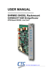
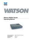
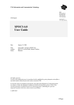
3. xDSL Series
3-1
xDSL Selection Table
IDSL
IDSL
I-DSL128
I-DSL64
2-wire 2B1Q Leased Line Modem
2-wire 2B1Q Leased Line Modem
Product
Type
S
S
Page
3-13
3-13
3-13
3-15
3-16
3-17
3-18
3-19
3-19
3-19
3-19
3-20
3-21
Testers
Network Type
SHRM03-E1
E1 to G.SHDSL, 2W/TDM
SHRM03-V35
V.35 to G.SHDSL, 2W/TDM
SHRM03-ET100
10/100 BASE TX to G.SHDSL, 2W/TDM
SHDTU03-E1
E1 to G.SHDSL, 2W/TDM
SHDTU03-V35
V.35 to G.SHDSL, 2W/TDM
SHDTU03-ET100 10/100 BASE TX to G.SHDSL, 2W/TDM
SHRM03-ET100R 10/100 BASE TX to G.SHDSL, 2W/ATM
SHDTU03-ET10R 2-wire SHDSL router
SHDTU03F-ET10R 2-wire SHDSL router with firewall protection
SHDTU03A4-wire SHDSL router
SHDTU03AF4-wire SHDSL router with firewall protection
ET10RS
I-DSL Family
Product Name
Description
Page
3
IP Networking
G.SHDSL TDM Series
G.SHDSL TDM Series
G.SHDSL TDM Series
G.SHDSL TDM Series
G.SHDSL TDM Series
G.SHDSL TDM Series
G.SHDSL ATM Series
G.SHDSL ATM Series
G.SHDSL ATM Series
G.SHDSL ATM Series
G.SHDSL ATM Series
Product
Type
L
L
L
S
S
S
L
S
S
S
S
3-3
3-4
3-5
3-6
3-7
3-7
3-8
3-8
3-8
3-8
3-9
3-10
3-11
3-12
xDSL Series
Network Type
6U, 19", 16 slots (384 loop max)
6.75U, 19", 20 slots (640 loop max)
1U, 19", 3/4 slots (96 loop max)
ADSL MDF Type filtter
ADSL splitter
ADSL/ VDSL micro filtter
Regional ADSL splitter for Italy
Regional ADSL splitter for UK
Regional ADSL splitter for Finland
Regional ADSL splitter for France
ADSL/ ISDN splitter
10/100M BASE TX to ADSL
(4) 10/100M BASE TX to ADSL
Digital Subscriber Line Access Multiplexer
G.SH-DSL Family
Product Name
Description
ALS-R50
ALS-R60
ALS-R100-32P
ALS-P10
ALS-12
ALS-M12
ALS-10-IT
ALS-10-UK
ALS-10-FI
ALS-10-FA
ALS-10-EU/I
ATU-R140
ATU-R210
MD-20
Page
Access Series
ADSL
ADSL
ADSL
ADSL
ADSL
ADSL
ADSL
ADSL
ADSL
ADSL
ADSL
ADSL
ADSL
ADSL
Product
Type
R
R
R
C
C
C
C
C
C
C
C
S
S
S
Fiber Series
R/Rack, L/Line card, S/Standalone, SW/Switch, C/Compact
A-DSL Family
Network Type
Product Name
Description
Interface
Converter
Datacom
Accessories
Network
Management
3-2
ADSL Family
ADSL Splitter Series
ALS-R50
Rack Type Splitter
The ALS-R50 rack connections are organized into two-card sets. Each physical card provides 24 loops. A two card set
provides 48 loops. Each card set provides high density connections to the central office DSLAM using 2-50 pin (2.54mm
pitch) locking header connector and ribbon cables. Each ribbon Connector supports 24 loops. POTS and line
connections are provided via two sets each of 12x4 wire wrap terminals.
Features
6U high 19" Rack
Consists exclusively of all passive elements
Specifications
Standard
Impedance
Insertion Loss
Designed for implementation of ADSL CO application
Handles all POTS loop current from 0mA to 100mA
Attenuation distortion
If the power supply or ATU-C/ATU-R fails, telephone service on
the ADSL line will operate normally
Provides excellent isolation between DSL and POTS
Up to 16 cards (384 loop max)
Cut off frequency
ADSL band
Attenuation
Delay Distortion
Return Loss
Application
Common Mode
Rejection Ration
DC Resistance
Isolation resistance to
Longitudinal
DC Current carrying
capacity
Environment
Dimensions(WxDxH)
Weight
Annex E.2 of ITU-T G.992.1
900 ohms
1004Hz short
1dB
loop
1004Hz Long
0.75dB
loop
200 to 3.4Khz
-1.5 — 1.5dB
short loop
3.4 to 300KHz -2 — 2dB
short loop
200 to 3.4KHz
-1.5 — 0.5dB
long loop
3.4 to 300KHz -1.5 — 1dB
long loop
-3dB
8Khz
30 — 300KHz
-65dB
300 — 1104KHz -55dB
600 — 3.2KHz
200us
200 — 4KHz
250us
ERL
8dB
SRL-L
5dB
SRL-H
5dB
600 — 3.2KHz
-100dB
20Ohms
5M Ohms
200 — 1KHz
1 — 3KHz
100mA
-60dB
-60dB
Temperature
-10 — 70°C (Operating);
-15 — 80°C (Storage)
Humidity
0 — 90% non condensing
434mm x 285mm x 265.6mm
18kg
Ordering Info
ALS-R50-P
ALS-R50 24P-11 Card
3-3
ADSL Line Splitter Rack, for CO
application, w/wire wrap and 50pin locking
ribbon cable connections
ADSL Line Splitter Card, 24 Loops, 600
ohm, 8k Hz
ADSL Family
Fiber Series
ADSL Splitter Series
ALS-R60
Access Series
Rack Type Splitter
The ALS-R60 is a rack mount solution for central office or service providers, containing up to 20 cards with 32 each
ADSL line splitters which provide low-pass filters designed to provide POTS (Plain Old Telephone System) service to a
line that is utilizing ADSL technology. This device is designed to eliminate interference to POTS equipment by blocking
the high frequency ADSL signal (20 KHz~12 MHz).
Features
Consists exclusively of all passive elements
Standard
Impedance
Insertion Loss
Designed for implementation of ADSL/ ADSL2/ ADSL2+
CO application
Handles all POTS loop current from 0mA to 100mA
Attenuation distortion
Provides excellent isolation between DSL and POTS
Up to 20 cards (640 loop max)
Return Loss
Application
DC Current carrying
capacity
Environment
-60dB
-60dB
Temperature
-10 — 70°C (Operating);
-15 — 80°C (Storage)
Humidity
0 — 90% non condensing
436mm x 300mm x 300mm
18kg
ALS-R60-8
ALS-R60 32P-11 Card
ADSL Line Splitter Rack, for CO
application, w/wire wrap and IDC 68pins
cable connections
ADSL Line Splitter Card, 32 Loops,
900 ohm, 8KHz
Network
Management
Ordering Info
Datacom
Accessories
Dimensions(WxDxH)
Weight
20Ohms
5M Ohms
200 — 1KHz
1 — 3KHz
100mA
Interface
Converter
Common Mode
Rejection Ration
DC Resistance
Isolation resistance to
Longitudinal
Testers
Cut off frequency
ADSL band
Attenuation
Delay Distortion
IP Networking
If the power supply or ATU-C/ATU-R fails, telephone service on
the ADSL line will operate normally
Annex E.2 of ITU-T G.992.3
900 ohms
1004Hz short
1dB
loop
1004 Hz Long
0.75dB
loop
200 to 3.4Khz
-1.5 — 1.5dB
short loop
3.4 to 300KHz -2 — 2dB
short loop
200 to 3.4KHz -1.5 — 0.5dB
long loop
3.4 to 300KHz -1.5 — 1dB
long loop
-3dB
8Khz
30 — 300KHz
-65dB
300 —1104KHz -55dB
600 — 3.2KHz 200us
200 — 4KHz
250us
ERL
8dB
SRL-L
5dB
SRL-H
5dB
600 — 3.2KHz -100dB
xDSL Series
8U high 19" Rack
3
Specifications
3-4
ADSL Family
ADSL Splitter Series
ALS-R100
Rack Type Splitter
The ALS-R100 is a rack mount solution for central office or service providers, which nests up to 3 cards containing 32
each ADSL line splitters or up to a maximum 96 loops. The splitter provides low-pass filters designed to provide POTS
(Plain Old Telephone System) service to a line that is utilizing ADSL technology. This device is designed to eliminate
interference to POTS equipment by blocking the high frequency ADSL signal (20 KHz~1.1MHz).The design of the ALS100 ensured that when maintenance job is performed on single loop, any insertion or removal will not cause any
interruption on any telephone service for any users on this card module.
Features
1U high 19" Rack, supports stacking
Consists exclusively of all passive components
Specifications
Standard
Impedance
Insertion Loss
Designed for implementation of ADSL CO application
Handles all POTS loop current from 0mA to 100mA
Attenuation distortion
If the power supply or ATU-C/ATU-R fails, telephone service on
the ADSL line will operate normally
Provides excellent isolation between DSL and POTS
Up to 3 slots for 32 loops line card (96 loop max)
When the telephone service is idle or occupied, any insertion or
removal of the card module will not cause any service break
Cut off frequency
ADSL band
Attenuation
Delay Distortion
Return Loss
Application
Common Mode
Rejection Ration
DC Resistance
Isolation resistance to
Longitudinal
DC Current carrying
capacity
Environment
Dimensions(WxDxH)
Weight
Compliance
Annex E.2 of ITU-T G.992.3
900 ohms
1004Hz short
1dB
loop
1004 Hz Long
0.75dB
loop
200 to 3.4Khz
-1.5 — 1.5dB
short loop
3.4 to 300KHz -2 — 2dB
short loop
200 to 3.4KHz -1.5 — 0.5dB
long loop
3.4 to 300KHz -1.5 — 1dB
long loop
-3dB
8Khz
30 — 300KHz
-65dB
300 —1104KHz -55dB
600 — 3.2KHz 200us
200 — 4KHz
250us
ERL
8dB
SRL-L
5dB
SRL-H
5dB
600 — 3.2KHz -100dB
20Ohms
5M Ohms
200 — 1KHz
1 — 3KHz
100mA
-60dB
-60dB
Temperature
-10 — 70°C (Operating);
-15 — 80°C (Storage)
Humidity
0 — 90% non condensing
443mm x 313mm x 44.5mm
card:1.2kg; empty chassis: 4.15kg;
total: 7.75kg
IEC61000-4-5 and FCC part 68
Ordering Info
ALS-R100-CH
ALS-R100-32P
PIN Assignment ALS-R100-32P
3-5
ADSL/VDSL Line Splitter Rack, for CO
application, w/wire wrap 78 pin
ADSL/VDSL Line Splitter Card, 32 Loops,
600 ohm, 8k Hz
ADSL Family
Fiber Series
ADSL Splitter Series
ALS-P10
The ALS-P10 filters can be directly plugged into the existing terminals of the CO one
by one, as needed, thus eliminating need for extra terminal blocks and cabling. This
leads to lower costs compared with ordinary splitters, which require operators to
install large splitter racks and equipment awaiting presumable future use. With
Siemens/ Krone type terminals, no extra cabling or terminal blocks are needed at all;
with Krone LSA Plus terminals only minor new cabling are needed. The plug type
filters are easy to install onto the terminal blocks; no tools are needed.
Features
Filter Type
Integrates directly in MDF, no racks required
Minimum number of contact points
POTS service available with splitter removed (make-before-break)
Tinned Krone LSA Plus test plug reed connectors
Over voltage
Dimensions(WxDxH)
Weight
Low pass
corner freq. 7kHz (±1kHz),
optimal matching 600ohms,
DC path max. 100mA
High pass
corner freq. 22kHz
(±2kHz), optimal matching
135ohms, no DC path
Filter adapted to POTS voltages
(max.±200V)
18mm x 104mm x 20mm
45g
IP Networking
Various splitter designs available (POTS, ISDN, ... )
3
Specifications
xDSL Series
Individual splitter
Filters act like disconnection plugs: the contacts inside the terminal are disconnected
and the filter connects in series to the pair. Individual filters can be plugged adjacent
to each other and they don't block neighboring pairs from insertion of new wires.
Thus ADSL can be connected to subscribers independently, which is an asset. The
plug type splitter requires the space of two pairs of LSA Plus terminal block.
Access Series
ADSL MDF Type Splitter
Testers
Application
Interface
Converter
Ordering Info
ADSL MDF Type Splitter
Datacom
Accessories
ALS-P10
Network
Management
3-6
ADSL Family
ADSL Splitter Series
ALS-12/ ALS-M12
ALS-12
ADSL Splitter and Micro Filter
The ALS-12/ ALS-M12 are low-cost, compact, passive low-pass filters designed to provide POTS (Plain Old Telephone
System) service to a line that is utilizing ADSL/VDSL technology. This device is designed to eliminate interference to
POTS equipment by blocking high frequency energy (20 KHz~12MHz).
ALS-M12
Features
Compact size
Consists exclusively of all passive elements
Specifications
Standard
Impedance
Insertion Loss
Designed for implementation of ADSL CPE application
Handles all POTS loop current from 0mA to 100mA
Attenuation distortion
If the power supply or ATU-C/ATU-R fails, telephone service on
the ADSL line will operate normally
Provides excellent isolation between DSL and POTS
The POTS splitter at remote end shall provide the RJ-11
connector for ATU-R/VTU-R line interface
The POTS splitter and Low-pass filter shall provide the RJ-11
connectors for ADSL/VDSL line interfaces as well as POTS
interface of splitter/Low-pass filter at remote end
Cut off frequency
ADSL band
Attenuation
Delay Distortion
Return Loss
Application
Common Mode
Rejection Ration
DC Resistance
Isolation resistance to
Longitudinal
DC Current carrying
capacity
Environment
Dimensions(WxDxH)
Weight
Annex E.2 of ITU-T G.992.3
600 Ohms
1004Hz short
1dB
loop
1004 Hz Long
0.75dB
loop
200 to 3.4Khz
-1.5 — 1.5dB
short loop
3.4 to 300KHz -2 — 2dB
short loop
200 to 3.4KHz -1.5 — 0.5dB
long loop
3.4 to 300KHz -1.5 — 1dB
long loop
-3dB
10KHz
30 — 300KHz
65dB
300 —
55dB
1104KHz
600 — 3.2KHz 200us
200 — 4KHz
250us
ERL
6dB
SRL-L
5dB
SRL-H
3dB
600 — 3.2KHz -100dB
20Ohms
5MOhms
200 — 1KHz
1 — 3KHz
100mA
Temperature
Humidity
ALS-12
ALS-M12
ALS-12
ALS-M12
58dB
53dB
-10 — 70°C (Operating);
-15 — 80°C (Storage)
0 — 90% non condensing
45mm x 34mm x 24mm
45mm x 34mm x 24mm
70g
70g
Ordering Info
ALS-12
3-7
ALS-12-C
ADSL Line Splitter for ADSL/VDSL CPE
application, 600 ohm, 8K Hz , DSL is RJ-11
ADSL Line Splitter with surge protector for
ADSL/VDSL CPE application, 600 ohm, 8K
Hz , DSL is RJ-11
ALS-M12
The ADSL/ VDSL micro Filter
ADSL Family
Fiber Series
ADSL Splitter Series
ALS-M10-IT/ UK/ FI/ FA
ALS-M10-IT(ITALY)
ALS-M10-UK(UK)
The ALS-10-IT/ UK/ FI/ FA are low-cost, compact, passive low-pass filter designed to provide POTS (plain Old
Telephone System) service to a line that utilizing ADSL technology. This device is designed to eliminate interference to
POTS equipment by blocking high frequency energy (20 KHz~1.1MHz).
ALS-M10-FI(Finland)
Features
Standard
Impedance
Connector
Insertion Loss
Designed for implementation of ADSL/VDSL CPE application
Handles all POTS loop current from 0mA to 100mA
Attenuation distortion
Provides excellent isolation between DSL and POTS
The POTS splitter at remote end shall provide the RJ-11
connector for ATU-R/VTU-R modem interface
Cut off frequency
ADSL band
Attenuation
Delay Distortion
Return Loss
Ordering Info
DC Current carrying
capacity
Environment
-15 — 70°C (Operating);
-10 — 80°C (Storage)
15 — 90% non condensing
2
2
3
3
LPF
PHONE
Weight
1
ALS-M10-IT/ UK/ FI
1
2
3
4
5
6
LPF
1
2
3
4
5
6
LINE
TBA
TBA
TBA
TBA
TBA
TBA
TBA
TBA
Network
Management
Compliance
1
2
3
4
5
6
ALS-M10-IT
ALS-M10-UK
ALS-M10-FI
ALS-M10-FA
ALS-M10-IT
ALS-M10-UK
ALS-M10-FI
ALS-M10-FA
ITU-T K.21
Datacom
Accessories
Dimensions(WxDxH)
1
MODEM
58dB
53dB
3
4
PHONE
Temperature
Humidity
2
LINE
20Ohms
5MOhms
200 — 1KHz
1 — 3KHz
100mA
Interface
Converter
Italy standard ADSL Splitter
UK standard ADSL Splitter
Finland standard ADSL Splitter
France standard ADSL Splitter
Common Mode
Rejection Ration
DC Resistance
Isolation resistance to
Longitudinal
Testers
The POTS splitter and Low-pass filter shall provide the Regional
connectors for ADSL/VDSL line interfaces as well as POTS
interface of splitter/Low-pass filter at remote end
IP Networking
If the power supply or ATU-C/ATU-R fails, telephone service on
the ADSL line will operate normally
Annex E.2 of ITU-T G.992.3.
600 Ohms
RJ-11
1004Hz short
1dB
loop
1004 Hz Long
0.75dB
loop
200 to 3.4Khz
-1.5 — 1.5dB
short loop
3.4 to 300KHz -2 — 2dB
short loop
200 to 3.4KHz -1.5 — 0.5dB
long loop
3.4 to 300KHz -1.5 — 1dB
long loop
-3dB
12KHz
30KHz
-25dB
50KHz
-40dB
600 — 3.2KHz 200us
200 — 4KHz
250us
ERL
6dB
SRL-L
5dB
SRL-H
3dB
600 — 3.2KHz -100dB
xDSL Series
Consists exclusively of all passive components
DSL
3
Specifications
Compact size
ALS-10-IT
ALS-10-UK
ALS-10-FI
ALS-10-FA
ALS-M10-FA(FRANCE)
Access Series
Regional ADSL/VDSL Splitters and Micro Filter
ALS-M10-FA
3-8
ADSL Family
ADSL Splitter Series
ALS-10-EU/I
ADSL ISDN Splitter
The ALS-10-EU/I is a low-cost, compact, designed to implement the functionality of
low pass filter in ISDN-BA with 2B1Q or 4B3T baseband linecodes over ADSL
application. It integrates low pass filters that block the high frequency energy from
reaching the ISDN-BA device and provide isolation from impedance effects of the
ISDN-BA device on ADSL. Because the ISDN splitter connects directly to the
subscriber loop media, it must also provide some protection for externally induced
line hits or faults which could damage any attached equipment or endanger humans
interacting with the installed equipment.
Features
Consists exclusively of all passive components
Designed for implementation of ADSL CPE application
The circuit protection will be provided mostly by standard central office line protection
means and additional protection measures built into splitter to protect against line
overstress which could damage the splitter itself. The electrical and transmission
specification is based on ETSI TS 101 952-1-3 V1.1.1 for ISDN-BA requirements.
Specifications
Standard
Impedance
Isolation
Handles all ISTN loop current from 0 to 60 mA
If the power supply or ATU-C/ATU-R fails, telephone service on
the ADSL line will operate normally
Provides excellent isolation between DSL and ISDN
Application
Insertion loss
Insertion loss in ADSL
band
Insertion loss between
ADSL port to LINE
port
ETSI TS 101-952-1-3 V.1.1.1
135/ 150 Ohms
Wire A to B
5 Mohms
DC
12.5 Ohms
resistance
1 — 40KHz
0.8dB
40 — 80KHz
2dB
1 — 60KHz
1.2dB
60 — 80KHz
2dB
150 —
65dB
1104KHz
120 — 170KHz 2dB
170 —
1104KHz
Return loss at ISDN
1 — 40KHz
port
40 — 80KHz
1 — 60KHz
60 — 80KHz
Unbalance about earth 300 — 30KHz
30 — 1104KHz
Group delay distortion
1104KHz —
3MHz
300 — 80KHz
Environment
Temperature
Humidity
Dimensions(WxDxH)
Weight
Compliance
1dB
16dB
14dB
16dB
14dB
40dB
46dB
40dB
20us
-10 — 60°C (Operating);
-10 — 80°C (Storage)
15 — 90% non condensing
56mm x 86mm x 26mm
70g
Annex E.2 of ITU-T G.992.1
Ordering Info
ALS-10-EU/I
3-9
European standard ADSL Splitter for
ISDN
ADSL Family
Fiber Series
ADSL Modem Series
ATU R-140
The new standards ADSL 2 and ADSL 2+ provide greater reach and higher data
rates. The two technologies were developed side by side, and are downwardly
compatible with the existing G.992.1 ADSL standard. ADSL 2+ (G.992.5) brings
ADSL access to users who until now were located too far from the operator's central
office. The increased reach is possible because of new modulation techniques in
conjunction with improved error correction through trellis coding.
Features
Specifications
ADSL/ADSL2/ADSL2+ supported
All Digital Loop ADSL supported
Comprehensive Firewall & Security Function
Ethernet supported for LAN connection
Reach Extended ADSL2 (READSL2) supported
UPnP NAT Traversal & Device Identification supported
USB Interface (Optional)
Specifications
Environment
Ordering Info
ATU-R140A
ATU-R140B
ADSL2/2+ Bridge/ Router Modem with
RJ-11 & RJ-45, Annex-A
ADSL2/2+ Bridge/ Router Modem with
RJ-11 & RJ-45, Annex-B
Network
Management
Application
Datacom
Accessories
Power Consumption
LEDs
Dimensions(WxDxH)
Weight
Compliance
One ADSL line RJ-11 port
Four LAN RJ-45 port for
10/100M Ethernet LAN
connection
9VDC, AC Power Adapter for 110VAC or
220VAC
Temperature
0 — 40°C (Operating);
-20 — 70°C (Storage)
Humidity
10 — 90%
10W
INTERNET/PPP, PWR, WAN, LAN
145mm x 175mm x 34mm
230g
FCC Part 15, CE
Interface
Converter
Power
WAN
LAN
Testers
Web-based interface for easy configuration
IP Networking
Cost-effective sharing of a single DSL connection
Software Specifications
ANSI T1.413 issue 2
ADSL Modem
All Digital Loop ADSL
G.994.1 (G.hs, Multimode)
ITU-T G.992.1 (G.dmt)/ITU-T G.992.2 (G.lite)
ITU-T G.992.3 (ADSL2 G.dmt.bis)/
ITU-T G.992.4(ADSL2.G.lite.bis)
ITU-T G.992.5
(ADSL2+, Annex A, B, I, J, L & M)
PPP over ATM PVC (RFC2364)
PPP supports
PPP over Ethernet (RFC2516)
PPP authentication:PAP, CHAP & MS-CHAP
Security
Demilitarized Zone (DMZ) Management
Utility Password-protected
Deny of Service (DoS) protection
Firewall with NAT
Packet Filtering ; Content Filtering
Stateful Packet Inspection (SPI) firewall
VPN pass through (IPsec, PPTP)
ATM Attributes
Adaptation Layers AAL5, AAL2 and AAL0
are supported
OAM F4/F5 loop back
Up to 8 PVCs
Bridge Filtering
Bridge Mode
IEEE 802.1D transparent bridging
RFC 1483 Bridge
DHCP (RFC1541) Server, Relay and Client
Router Mode
DNS relay/ IGMP v1 and v2/ ToS supported
Network Address Translation (NAT)/ Network
Address Port Translation (NAPT)
RFC 1483 Route/ IPoA (RFC1577)
RIP 1 & 2 supported
Regulatory Approvals FCC Part 15 ; FCC Part 68, CE,
LVD (upon customer's request)
Quality of Service
Constant Bit Rate (CBR), Real-Time
(QoS)
Variable Bit Rate (VBR-rt), Non-Real-Time
Variable Bit Rate (VBR-nrt) and Unspecified
Bit Rate (UBR)
Remote/ local configuration & management
Management
through SNMP v1/v2, web and telnet
Firmware upgrade and reset to default via
Web management
3
xDSL Series
Texas Instruments Chip solution
General Specification
Physical Interface
Essentially an upgrade to traditional ADSL technologies, ADSL 2+ brings the
possibility of multi-megabit bandwidth and greater reach for broadband
services,meaning easy deployment and expansion into rural areas, where coverage
is low. With up to 24 megabit connections possible, mass-market applications such
as video on demand, premium access and networked gaming are improved
tremendously.
Access Series
ADSL2+ Bridge/ Router Modem
3-10
ADSL Family
ADSL Modem Series
ATU R-210
ADSL2+ Bridge/ Router Modem
The new standards ADSL 2 and ADSL 2+ provide greater reach and higher data
rates. The two technologies were developed side by side, and are downwardly
compatible with the existing G.992.1 ADSL standard. ADSL 2+ (G.992.5) brings
ADSL access to users who until now were located too far from the operator's central
office. The increased reach is possible because of new modulation techniques in
conjunction with improved error correction through trellis coding.
Features
Specifications
Broadcom Chip solution
ADSL/ADSL2/ADSL2+ supported
Asymmetrical data rate up to 24 Mbps downstream and upstream
up to 2.5 Mbps
Browser-based configuration environment
Firmware upgrade available from TFTP via Ethernet port
Support both bridging or routing and PPP function modes
Support ITU-T G.992.3, ITU-T G.992.4 & ITU-T G.992.5
Specifications
General Specification
Standard
Physical Interface
ITU-T G.992.1, G.992.2, G.992.3, G.992.4,
G.992.5
WAN
One ADSL line RJ-11 port
LAN
Power
Environment
Power Consumption
LEDs
Dimensions(WxDxH)
Weight
Compliance
MTBF
Application
Essentially an upgrade to traditional ADSL technologies, ADSL 2+ brings the
possibility of multi-megabit bandwidth and greater reach for broadband
services,meaning easy deployment and expansion into rural areas, where coverage
is low. With up to 24 megabit connections possible, mass-market applications such
as video on demand, premium access and networked gaming are improved
tremendously.
Four LAN RJ-45 port for
10/100M Ethernet LAN
connection
15 VDC, AC Power Adapter for 110VAC or
220VAC
Temperature
0 — 40°C (Operating);
-20 — 70°C (Storage)
Humidity
10 — 90%
10W
INTERNET/PPP, PWR, WAN, LAN
145mm x 130mm x 34mm
250g
FCC Part15,16 CE
60000 hrs
Software Specifications
ADSL Modem
ANSI T1.413 issue 2
All Digital Loop ADSL
G.994.1 (G.hs, Multimode)
ITU-T G.992.1 (G.dmt)/
ITU-T G.992.2 (G.lite)
ITU-T G.992.3 (ADSL2 G.dmt.bis)/
ITU-T G.992.4(ADSL2.G.lite.bis)
ITU-T G.992.5 (ADSL2+,
Annex A, B, I, J, L & M)
PPP over ATM PVC (RFC2364)
PPP supports
PPP over Ethernet (RFC2516)
PPP authentication:PAP, CHAP & MS-CHAP
Security
Demilitarized Zone (DMZ) Management
Utility Password-protected
Deny of Service (DoS) protection
Firewall with NAT
Packet Filtering ; Content Filtering
Stateful Packet Inspection (SPI) firewall
VPN pass through (IPsec, PPTP)
ATM Attributes
Adaptation Layers AAL5, AAL2 and AAL0
are supported
OAM F4/F5 loop back
Up to 8 PVCs
Bridge Filtering
Bridge Mode
IEEE 802.1D transparent bridging
RFC 1483 Bridge
DHCP (RFC1541) Server, Relay and Client
Router Mode
DNS relay/ IGMP v1 and v2/ ToS supported
Network Address Translation (NAT)/ Network
Address Port Translation (NAPT)
RFC 1483 Route/ IPoA (RFC1577)
RIP 1 & 2 supported
Regulatory Approvals FCC Part 15 ; FCC Part 68, CE, LVD (upon
customer's request)
Constant Bit Rate (CBR), Real-Time
Quality of Service
Variable Bit Rate (VBR-rt), Non-Real-Time
(QoS)
Variable Bit Rate (VBR-nrt) and Unspecified
Bit Rate (UBR)
Remote/ local configuration & management
Management
through SNMP v1/v2, web and telnet
Firmware upgrade and reset to default via
Web management
Ordering Info
ATU-R210
3-11
Standalone ADSL2+ Bridge/Router Modem,
with 4-port switch HUB
ADSL Family
Fiber Series
ADSL2+ Mini DSLAM
MD-20
Access Series
Digital Subscriber Line Access Multiplexer
The MD-20 is a mini-DSLAM designed for efficient scalability and easy deployment for access networks. This broadband
access solution provides an exceptional way to extend ADSL reach further from central office DSLAM equipment to new
customers, resulting in increased revenue generating service for both IP and ATM networks. The energy-efficient
compact enclosure design fits perfectly inside temperature hardened and space limited rack space of telecommunication
curbside cabinet.
Features
Supports ADSL, ADSL2, ADSL2+ via POTS/ISDN interface
General Specifications
Power
Environment
Provides 24 ~ 72 ports of ADSL in one 2U chassis
Modular design with hot swappable and field replaceable units
System Overheating Protection
Compliance
Full diagnostic and alarm reporting capability
MTBF
SNMP, Telnet, CLI and Web based management
Interface Cards
Network Interface
Dual A+B -48V DC power input terminal
1.25G SFP
SFM-7000-S85
SFS-7010-L31
SFS-7040-L31
SFS-7080-Z55
ADSL 24L ETSI 270 Splitter Annex-A
ADSL 24L ISDN Spliter Annex-B
SHDSL 24L W/O WET Current Annex-A/B,
2 wire, ATM base
Network
Management
Line Card
MD-00-AL5A
MD-00-AL5B
MD-00-SL6A
Datacom
Accessories
MD-20 Mini DSLAM Chassis
MD-20-MA1A
19" 2U Rack mount Chassis Up to 3 slots + 1
Slot (for Network Interface card) With DC power
& Cooling Fan& Filter
Trunk Card
2 x 100/1000 Based-TX or 2 x SFP uplink Card (IP)
MD-00-GE1A
MD-00-IM8A
8 x E1 IMA Uplink card (ATM)
MD-00-ST1A
STM-1 155M uplink card (ATM)
Subscriber Interface
24 ports card
Service Characteristics
QoS (UBR, rt-VBR, nrt-VBR, CBR)
ATM
PVC default priority and PVC-to-VLAN
mapping
Traffic scheduling/shaping/policing
Ethernet
IEEE 802.1d Spanning tree protocol (STP)
IEEE 802.3ad Link aggregation
IEEE 802.1g port (Tag Based/ LAN)
Security on console access
OSI Layer 2
MAC filtering and count limit
Functionality
Access control list (ACL)
Hardware-based multicasting
Broadcast control and broadcast rate limit
Port-based virtual local area network (VLAN)
IGMP snooping v1 and v2
SNMP v1 and v2c
Remote Monitoring (1, 2, 3, 9 groups)
Management Information Base (MIB)
RFC 2514, 2515 ATM MIB, RFC 1213 SNMP MIB II, RFC 1493
Bridge MIB, RFC 1643 Ethernet MIB, RFC 2674 Q MIB, RFC 1757
RMON MIB, group 1,2,3,9, IMA-MIB, SHDSL Line-MIB, ADSL Line
MIB, CTC Union proprietary MIB
Interface
Converter
Ordering Info
STM-1
8 x E1 IMA
2 x 10/100/1000 Based-Tx or 2 x 1000
Base-FX SFP
ADSL2+/POTS/ISDN (G.992.1 .2 .3 .5)
Testers
Application
-48 (-42 — -56)VDC
-40 — 65°C (Operating);
0 — 70°C (Storage)
Humidity
5 — 95% non condensing
130W (maximum)
482mm x 304mm x 88mm
4.4 Kg with no units installed, fan card 2U:
0.25 Kg
ITU-T K.20, K.21, ETSI 300-019, 300-386,
EN 60950, Conform to CE requirements
20150 hours
IP Networking
Build-in POTS/ISDN Splitters
Power Consumption
Dimensions(WxDxH)
Weight
DC
Temperature
3
xDSL Series
Bring ADSL service to previously unreachable customers
Specifications
MM, 550m, 850nm, LC, 8.5dBm, (w/o DD)
SM, 10km, 1310nm DFB, LC, 10.5dBm (w/o DD)
SM, 40km, 1310nm DFB, LC, 19dBm (w/o DD)
SM, 80km, 1550nm DFB, LC, 23dBm (w/o DD)
3-12
G.SHDSL Family
TDM Modem Series
SHRM03-E1/ V35/ ET100
G.SHDSL Modem Concentrator
The SHRM03 offers Three different ways to connect customers over high-speed DSL services; TDM based G.703 E1,
TDM based serial DCE port or TDM based Ethernet Bridge. The SHRM03 is equipped with an adaptive auto rate
capability that identifies the maximum line rate supported by the copper loop. This powerful automatic configuration
capability makes installation and service provisioning simple and painless. Further flexibility is provided by the ability to
manually set the maximum speed at different levels for different customer-tailored service offerings. This Rack is 100%
compatible with our SHDTU03 standalone CPE modem.
Features
Specifications
All interface connectors on the rear panel
Central solution in standard 19 inch rack
General Specif ication
Power
Env ironment
Downloadable software for easy upgrade
E1 and fractional E1 capable
Each line card supports two channels of single pair (two-wire)
for E1/Datacom/Ethernet solution N x 64k rate selectable from
64kbps to 2.304Mbps
Hot swappable cards and redundant (optional) power supplies
Menu oriented console screens for ease of use
Optional SNMP network management system card
Up to 13 cards (26 loops) can be installed + 1 SNMP card
Specifications - Software
Software Specifcation
Performance
Diagnostic
LEDs indication
3-13
SHDSL PM
ES-crc, SES-crc, UAS,
LOSW seconds
E1 PM
ES, SES, UAS seconds
Current 15-minute period and 96 previous
15-minute periods of SHDSL and E1
performance parameters
Current 24-hour period and 7 previous
24-hour periods of SHDSL and E1
performance parameters
E1 line loopback
V.54 loopback
Local SHDSL loopback
Remote SHDSL loopback
Remote payload loopback (Specifications
are subject to change without notice)
E1
PWR, SHDSL, FE1, LOF,
LOS, TEST, LOOP,
ALARM, and FAR ALARM
V.35
PWR, SHDSL, TD, RD,
CTS, TEST, LOOP,
ALARM, and FAR ALARM
Ethernet
PWR, SHDSL, 10M/ACT,
100M/ACT, COL, TEST,
LOOP, ALARM, and FAR
ALARM
Power Cunsumption
Dimensions(WxDxH)
Weight
E1 Specif ications
Line code
Data rate
Operation
Impedance
Framing
Timing
Jitter perf ormance
Connectors
AC 100V/ 220V, DC -48V
Temperature
0 — 50°C (Operating);
20 — 70°C (Storage)
Humidity
5% — 90% non-condensing
100W
438 x 285 x 180mm
6.5kg
HDB3/ AMI
64 — 2048kbps
Full or Fractional
120 ohms balanced/ 75 ohms unbalanced
Structured with or without CRC-4 or
Internal clock or G.703 recov ery
ITU-T G.823
BNC f or unbalanced, 5 pin wire connector or
RJ-45 f or balanced
Transmit lev el
Pulse
Nominal 2.37V+10% f or 75
amplitude
ohm
Nominal 3.00V+10% f or
120 ohm
Zero amplitude 0.1V
Transmit f requency
Internal timing ± 30ppm
Loopback
± 50ppm
tracking
timing
External timing ± 100ppm
Ethernet Interf ace Specif ications
IEEE 802.3/IEEE 802.3u
Standard
Raw HDLC
Encapsulation
packet size
maximum 1536
SHDSL Interf ace Specif ications
Standard
ITU-T G.991.2
Line code
16 lev el Trellis coded PAM
Data rate
64kbps — 2.304Mbps
Support
ANSI (Annex A) and ETSI (Annex B)
Datacom Interf ace Specif ications
Data Rate
64kbps — 2304kbps
Connectors
HD26 (cable adapters av ailable)
Timing
Internal, External
Application
Ordering Info
Fiber Series
SHRM03-SNMP
3
xDSL Series
Rack Mount SHRM03 Chassis
SHRM03-AA/CH
4U, 19" 14 slots Chassis for AC + AC
Power
SHRM03-AD/CH
4U, 19" 14 slots Chassis for AC + DC
Power
SHRM03-DD/CH
4U, 19" 14 slots Chassis for DC + DC
Power
SHRM03-AC
AC100V, AC220V Power Module
SHRM03-SNMP
SNMP I/F card with MIB and Console cable
Access Series
SHRM03-AC
IP Networking
Testers
SHRM03-E1/2T
Optional Line Card
SHRM03-E1/2T
SHRM03-ET100/2T
G.SHDSL (2W) E1 (2 channels)
TDM line card with E1 connector adapters
G.SHDSL (2W) V35 (2 channels)
TDM line card
G.SHDSL (2W) 10/100Base
TX Bridge (2 channels) TDM line card with
RJ-45 adapters
Interface
Converter
SHRM03-V35/2T
SHRM03-V35/2T SHRM03-ET100/2T
Datacom
Accessories
Network
Management
3-14
G.SHDSL Family
TDM Modem Series
SHDTU03-E1
E1 SHDSL Modem
The SHDTU03-E1 connects customers to high-speed G.703 E1 services via TDM based G.SHDSL at up to 2.048Mbps.
The SHDTU03-E1 is configured and managed via a menu-driven VT-100 compatible asynchronous terminal interface on
RS-232. The SHDTU03-E1 acts as either a CO or CPE in point-to-point applications or as a CPE device when
connected to our SHRM03 TDM based rack.
Features
Adaptive rate installation maximizes data rate based on loop
conditions
Bandwidth guaranteed transmission equipment
Can operate in back to back configurations
Efficient single wire pair usage
Fast and cost-effective provisioning of traditional or TDM leased
line services
Specifications
Line Rate
Coding
Support
Payload rates
Connector
Framing
DSL Timing
G.703 Interface
Loopback
Local management interface with LCD display
Raw and time stamped statistics
Performance
Monitoring
Remote loopback
Power
SHDSL Line performance monitoring
Environment
Standard G.SHDSL (ITU G.991.2) support for improved reach/
speed and greater interoperability
Use existing copper loop infrastructures
Up to 2.048Mbps symmetrical service bit rate
Application
Power Cunsumption
Dimensions(WxDxH)
Weight
Compliance
Ordering Info
SHDTU03-E1/2T-AC
SHDTU03-E1/2T-DC
3-15
SHDSL per ITU G.991.2
Trellis coded pulse amplitude modulation
ANSI (Annex A) and ETSI (Annex B)
192kbps to 2.048Mbps
RJ-45
G.703/G.704 (unframed / framed)
CRC 4 enable/disable
Network (Recovery)/ Internal/ DTE
RJ-48C for E1(120ohms) &
BNC for E1 (75 ohms)
Local Loopback/ Digital Loopback
Remote Loopback/ Built-in bit error rate
tester
ES, SES, UAS, Alarms, Errors for E1/T1*,
SHDSL
Threshold Crossing Notification
AC
90 — 240VAC
DC
-48VDC
Temperature
0 — 50°C (Operating);
20 — 70°C (Storage)
Humidity
5% — 90% non-condensing
10W
19.5cm x 16.8cm x 4.8cm
850g
CE, FCC
G.703 E1 interf ace, LCD panel & AC Ty pe
G.703 E1 interf ace, LCD panel & DC Ty pe
G.SHDSL Family
Fiber Series
TDM Modem Series
SHDTU03-V35
Access Series
Datacom SHDSL Modem
The SHDTU03-V35 connects customers to high-speed data communication services via TDM based G.SHDSL at up to
2.304Mbps. The SHDTU03-V35 is configured and managed via a menu-driven VT-100 compatible asynchronous
terminal interface on RS-232. The SHDTU03-V35 acts as either a CO or CPE in point-to-point applications or as a CPE
device when connected to our SHRM03 TDM based rack. This modem is equipped with an adaptive rate capability that
identifies the maximum line rate supported by the copper loop. This powerful feature makes installation and service
provisioning simple and painless.
Features
Bandwidth guaranteed transmission equipment
Can operate in point-to-point configurations
Efficient single wire pair usage
Local management interface with LCD display
Raw and time stamped statistics
Performance
Monitoring
Power
Environment
Remote loopback
Standard G.SHDSL (ITU G.991.2) support for improved reach/
speed and greater interoperability
Power Cunsumption
Dimensions(WxDxH)
Weight
Compliance
Testers
SHDSL Line performance monitoring
SHDSL per ITU G.991.2
Trellis coded pulse amplitude modulation
ANSI (Annex A) and ETSI (Annex B)
192kbps to 2.304Mbps
RJ-45
Network (Recovery)/ Internal/ DTE
Local Loopback/ Digital Loopback
Remote Loopback/ Built-in bit error rate
tester
ES, SES, UAS, Alarms, SHDSL
Threshold Crossing Notification
AC
90 — 240VAC
DC
-48VDC
Temperature
0 — 50°C (Operating);
20 — 70°C (Storage)
Humidity
5% — 90% non-condensing
10W
19.5cm x 16.8cm x 4.8cm
850g
CE, FCC
IP Networking
Fast and cost-effective provisioning of traditional TDM leased
line services
Line Rate
Coding
Support
Payload rates
Connector
DSL Timing
Loopback
3
xDSL Series
Adaptive rate installation maximizes data rate based on loop
conditions
Specifications
Use existing copper loop infrastructures
Up to 2.304Mbps symmetrical service bit rate
SHDTU03-V35/2T-AC
Application
SHDTU03-V35/2T-DC
SHDTU03-X.21/2T-AC
SHDTU03-449/2T-AC
SHDTU03-449/2T-DC
SHDTU03-530/2T-DC
SHDTU03-530/2T-DC
Datacom
Accessories
SHDTU03-X.21/2T-DC
Network
Management
G.703 V.35 interface, LCD panel & AC
Type with DB25 Male to MB34 Female
G.703 V.35 interface, LCD panel & DC
Type with DB25 Male to MB34 Female
G.703 X.21 interface, LCD panel & AC Type
with DB25 Male to DB15 Female Cable
G.703 X.21 interface, LCD panel & DC
Type with DB25 Male to DB15 Female
G.703 449 interface, LCD panel & AC Type
with DB25 Male to DB37 Female Cable
G.703 449 interface, LCD panel & DC Type
with DB25 Male to DB37 Female Cable
G.703 530 interface, LCD panel & AC Type
with DB25 Male to DB25 Female Cable
G.703 530 interface, LCD panel & DC Type
with DB25 Male to DB25 Female Cable
Interface
Converter
Ordering Info
3-16
G.SHDSL Family
TDM Modem Series
SHDTU03-ET100
Ethernet SHDSL Modem
The SHDTU03-ET100 connects customers to Ethernet Bridging via TDM based G.SHDSL at up to 2.304Mbps. The
SHDTU03-ET100 is configured and managed via a menu-driven VT-100 compatible asynchronous terminal interface on
RS-232. The SHDTU03-ET100 acts as either a CO or CPE in point-to-point applications or as a CPE device when
connected to our SHRM03 TDM based rack. This modem is equipped with an adaptive rate capability that identifies the
maximum line rate supported by the copper loop. This powerful feature makes installation and service provisioning
simple and painless.
Features
Adaptive rate installation maximizes data rate based on loop
conditions
Bandwidth guaranteed transmission equipment
Can operate in point-to-point configurations
Efficient single wire pair usage
Fast and cost-effective provisioning of traditional frame relay
(FR or T-HDLC) or TDM leased line services
Local management interface with LCD display
Raw and time stamped statistics
Specifications
Line Rate
Coding
Support
Payload rates
Connector
DSL Timing
Loopback
Performance
Monitoring
Power
Environment
Remote loopback
SHDSL Line performance monitoring
Standard G.SHDSL (ITU G.991.2) support for improved reach/
speed and greater interoperability
Power Cunsumption
Dimensions(WxDxH)
Weight
Compliance
SHDSL per ITU G.991.2
Trellis coded pulse amplitude modulation
ANSI (Annex A) and ETSI (Annex B)
192kbps to 2.304Mbps
RJ-45
Network (Recovery)/ Internal/ DTE
Local Loopback/ Digital Loopback
Remote Loopback/ Built-in bit error rate
tester
ES, SES, UAS, Alarms, SHDSL
Threshold Crossing Notification
AC
90 — 240VAC
DC
-48VDC
Temperature
0 — 50°C (Operating);
20 — 70°C (Storage)
Humidity
5% — 90% non-condensing
10W
19.5cm x 16.8cm x 4.8cm
850g
CE, FCC
Use existing copper loop infrastructures
Up to 2.304Mbps symmetrical service bit rate
Ordering Info
Application
SHDTU03-ET100/2T-AC
SHDTU03-ET100/2T-DC
3-17
10/100 Base-T Ethernet interface, LCD
panel & AC Type
10/100 Base-T Ethernet interface, LCD
panel & DC Type
G.SHDSL Family
Fiber Series
ATM Modem Series
SHRM03-ET100R
Access Series
G.SHDSL Modem Concentrator
The SHRM03 ATM based line card rack allows customers to concentrate their G.SHDSL ATM based bridge/router
Ethernet lines into a central location with hot swappable capabilities and redundant power supplies. The SHRM03 ATM
line card is equipped with two independent channels that support adaptive auto-rate, Annex A or Annex B, bridging or
routing, and embedded SNMP, Telnet and Web interface for provisioning and management. This rack is 100% compatible
with our SHDTU03/ET10R and ET10RS standalone cpe modems.
SHRM03-ET100R Line Card
Features
Specifications - SHRM03-ET100R
Central solution in 19" rack
Software upgrade via TFTP or Web interface
IP based in-band management
Web browser screens for easy use
SNMP agent embedded in each channel
Specifications
Power Consumptin
Dimensions (WxDxH)
Weight
AC 100V/ 220V, DC -48V
Temperature
0 — 50°C (Operating);
20 — 70°C (Storage)
Humidity
5% — 90% non-condensing
100W
438 x 285 x 180mm
6.5kg (empty chassis)
SHRM03-ET100R
Network
Management
Rack Mount SHRM03 Chassis
SHRM03-AA/CH
4U, 19" 14 slots Chassis for AC + AC
Power
SHRM03-AD/CH
4U, 19" 14 slots Chassis for AC + DC
Power
SHRM03-DD/CH
4U, 19" 14 slots Chassis for DC + DC
Power
SHRM03-AC
AC100V, AC220V Power Module
Datacom
Accessories
Ordering Info
Interface
Converter
General Specification
Power
Environment
Testers
Up to 13 cards (26 loops) may be placed in one rack
IP Networking
Each card supports two channels of single pair (two wire) for
Ethernet Bridging or Routing solution at nx64 rates up to
2.304Mbps.
Hot swappable cards and redundant (optional) power supplies
Routing
DHCP server, client and relay (RFC2131/ 2132)
DNS relay and caching (RFC1034/ 1035)
IP multicast and IGMP proxy (RFC1112/ 2236)
IP routing with static routing and RIPv1/ RIPv2 (RFC1058/ 2453)
NAT ALGs for ICQ/ Netmeeting/ MSN/ Yahoo Messenger
Network address translation (NAT/ PAT) (RFC1631)
Support IP/TCP/UDP/ARP/ICMP/IGMP protocols
Bridging
IEEE 802.1D transparent learning bridge
IEEE 802.1q VLAN
Spanning tree protocol
Security
Advanced Stateful packet inspection (SPI) firewall (Optional Firewall
Router)
Application level gateway for URL and keyword blocking (Firewall
Router)
DMZ host/ Multi-DMZ/Multi-NAT function
Natural NAT firewall
User access control: deny certain PCs access to Internet service
(Firewall Router)
Virtual server mapping (RFC1631)
VPN pass-through for PPTP/ L2TP/ IPSec tunneling
Management
Easy-to-use web-based GUI for quick setup, configuration and
management
Menu-driven interface/Command-line interface (CLI) for Telnet
access
Password protected management and access control list for
administration
SNMP management with SNMPv1/ SNMPv2 (RFC1157/ 1901/ 1905)
agent and MIB II(RFC1213/ 1493)
Software upgrade via web-browser/ TFTP server
ATM
AAL5
OAM F5 AIS/RDI and loopback
Up to 8 PVCs
ATM QoS
CBR (Constant bit rate)
UBR (Unspecified bit rate)
VBR-rt (Variable bit rate real-time)
VBR-nrt (Variable bit rate non-real-time)
AAL5 Encapsulation
Classical IP over ATM (RFC 1577)
Ethernet over ATM (RFC 2684/1483)
PPP over ATM (RFC 2364)
VC multiplexing and SNAP/LLC
PPP
PPP over ATM for fixed and dynamic IP (RFC 2364)
PPP over Ethernet for fixed and dynamic IP (RFC 2516)
User authentication with PAP/CHAP/MS-CHAP
xDSL Series
All interface connections on the rear panel
3
G.SHDSL (2loop/2W) 10/100Base-T
Ethernet Router and Bridge (2 channels)
ATM Base Line card
3-18
G.SHDSL Family
ATM Modem Series
SHDTU03-ET10R/ SHDTU03F-ET10R
SHDTU03A-ET10RS/ SHDTU03AF-ET10RS
2-Wire/ 4-Wire SHDSL Router with single port or 4-port Switching Hub
The SHDTU03 ATM modem series are G.SHDSL2-wire/ 4-wire routers which comply with G.991.2 standards. The
SHDTU03 family provides business-class, multi-range 64Kbps to 2.304/4.608Mbps payload rates over exiting single
pair or two pairs copper wire. The SHDTU03, SHDSL router, is designed not only to optimize the service bit rate from
central office to customer premises but also integrates high-end Bridging/ Routing capabilities with advanced functions
such as Multi-DMZ, virtual server mapping and VPN pass-through. The SHDSL router allows customers to leverage
the latest in broadband technologies to meet their growing data communication needs.
Features
Adaptive rate installation maximizes data rate based on loop
conditions
Specifications
General Specification
Standard
LEDs
Bandwidth guaranteed transmission equipment
G991.2
General
WAN
LAN
Can operate in point-to-point configurations
Efficient single wire pair usage
'A' model support 4 wire operation
Raw and time stamped statistics
SHDSL Line performance monitoring
Standard G.SHDSL (ITU G.991.2) support for improved reach/
speed and greater interoperability
PWR
LNK, ACT
10M/ACT,
100M/ACT (1-port router)
ALM
-48VDC
0 — 45°C (Operating);
20 — 70°C (Storage)
0% — 95% non-condensing
Power
Environment
SHDSL
DC
Temperature
Power Cunsumption
Dimensions(WxDxH)
Weight
Compliance
MTBF
Humidity
9W
18.7cm x 14.5cm x 3.3cm
400g
CE, FCC
TBA
Use existing copper loop infrastructures
Up to 2.304Mbps (2-wire) or 4.608Mbps (4-wire) symmetrical
service bit rate
Ordering Info
SHDTU03-ET10R
Application
SHDTU03-ET10RS
SHDTU03F-ET10R
SHDTU03F-ET10RS
SHDTU03A-ET10R
SHDTU03A-ET10RS
SHDTU03AF-ET10R
SHDTU03AF-ET10RS
Standalone 2-wire SHDSL router with single
Ethernet port
Standalone 2-wire SHDSL router with 4-port
switching HUB
Standalone 2-wire SHDSL router with firewall
protection and single Ethernet port
Standalone 2-wire SHDSL router with firewall
protection and 4-port switching HUB
Standalone 4-wire SHDSL router with 4-port
switching HUB
Standalone 4-wire SHDSL router with single
Ethernet port
Standalone 4-wire SHDSL router with firewall
protection and single Ethernet port
Standalone 4-wire SHDSL router with firewall
protection and 4-port switching HUB
Single port rear
4-port rear
3-19
I-DSL Family
Fiber Series
IDSL Modem Series
I-DSL128
DSL128 (Network Termination Unit) is designed for high speed data communication
and internetworking transport services. It utilizes 2B1Q line coding and echo
cancellation technique for full duplex and synchronous data transmission over a 2wire line up to 5.5 Km. I-DSL128 supports power-on self-test and diagnostic
capability for optimal speed calibration and trouble shooting. The diagnostic
capabilities include Analog loopback, Digital loopback and BER Test. I-DSL128 is
elegantly designed and easy to operate.
Features
DTE interface alternatives: EIA 530, RS449(via DB37), V.35
(via M34), V.36(via DB37)
Line Coding: 2B1Q
Menu-driven LCD (16 x 2), control panel for easy operation
Synchronous: 64K or 128Kbps
Full duplex with adaptive echo cancellation
2B1Q
Unconditioned twisted pair, 19-26 AWG
Meets FCC Part 68 subpart D
RJ-11
I-DSL128-AC
Standalone IDSL Modem, 2-wire, 2B1Q
leased line CPE modem with one DTE
interface connector, LCD panel, AC type
Datacom
Accessories
Ordering Info
Interface
Converter
Local Loopback
ITU-T V.54 DTE Loopback
ANSI T1.601 Payload Loopback
Operation Range (BER<10 -7)
Up to 5.5Km over 26 gauge wire
2-wire mode
Up to 7.0Km over 24 gauge wire
Customer DTE Interface
1+1(optional)
Number of Ports
64K or 128Kbps (synchronous)
Data Rate
EIA530, RS449 (via DB37 adapter), V.35
Connector
(via M34 adapter), V.36 (via DB37 adapter)
Gereral Specifications
Standard
TBA
Internal, Line, DTE-A or DTE-B
Clock Source
4 operation keys
Keypad
LEDs
PWR, ACT, TST, DTE-A [TD, RD, ERR],
DTE-B [TD, RD, ERR]
Power
AC
100 — 240VAC
Temperature
0 — 50°C (Operating);
Environment
-20 — 65°C (Storage)
Humidity
10 — 90% non condensing
Power Consumption
10W
Dimensions(WxDxH)
19.5cm x 16.8cm x 4.8cm
Weight
850g
Compliance
CE, FCC
MTBF
TBA
Testers
Application
Network Interface
Type
Line coding
Line type
Surge protection
Connector
Diagnostics Test
Loopbacks
IP Networking
IRange: Up to 5.5Km over 26 gauge wire
3
Specifications
xDSL Series
2-wire full duplex operation
Its front panel is equipped with one 16 x 2 LCD, 4 push-buttons for configuration and 9
LEDs for status indication. The configuration procedure goes through a friendly menudriven program. I-DSL128 is designed and suitable for providing Remote Access,
LAN/WAN interconnection, Host connection, Internet transport etc. meeting high speed
data services.
Access Series
2-wire 2B1Q Leased Line Modem
Network
Management
3-20
I-DSL Family
IDSL Modem Series
I-DSL64
2-wire 2B1Q Leased Line Modem
I-DSL64 is a G.703 64K co-directional Network Termination Unit designed for low-speed data communication and
internetworking transport services. It utilizes 2B1Q line coding and echo cancellation technique for full duplex and
synchronous data transmission over a 2-wire line up to 5.5 Km. I-DSL64 supports power-on self-test and diagnostic
capability for troubleshooting. The diagnostic capabilities include analog loopback, digital loopback and BERT TEST. IDSL64 is an easy to operate and elegantly designed equipment. Its front panel is equipped with one 2 x 16 LCD, 4
buttons for configuration and 7 LEDs for status indication. The configuration procedure goes through a friendly menudriven program.
Features
2-wire full duplex operation
Line coding: 2B1Q
Menu-driven LCD (2 x 16), control panel for easy operation
Range: Up to 5.5Km over 26 gauge wire
Synchronous: G.703/64KCo-directional
Application
Specifications
Network Interface
Type
Line coding
Line type
Surge protection
Connector
Diagnostics Test
Loopbacks
Full duplex with adaptive echo cancellation
2B1Q
Unconditioned twisted pair, 19-26 AWG
Meets FCC Part 68 subpart D
RJ-11
Local Loopback
ANSI T1.601 Payload Loopback
Operation Range (BER<10 -7)
Up to 5.5Km over 26 gauge wire
2-wire mode
Up to 7.0Km over 24 gauge wire
Customer G703/64K Co-directional interface
Data rate
64K
Connector
DB15 Female
Line Code
Co-directional
Gereral Specifications
Standard
G.703
LEDs
PWR, ERR, SYNC, BERT, Tx, Rx
AC
Power
90 — 240VAC
-48VDC
DC
Environment
Temperature
5 — 50°C (Operating);
-20 — 65°C (Storage)
10 — 90% non condensing
Power Consumption
Dimensions(WxDxH)
Weight
Compliance
MTBF
Humidity
10W
19.5cm x 16.8cm x 4.8cm
850g
CE, FCC
TBA
Ordering Info
I-DSL64
3-21
Standalone IDSL Modem, 2-wire, 2B1Q
leased line CPE modem, support G.703/64
co-directional transmission LCD panel,
support AC or DC type.