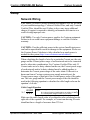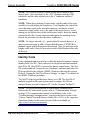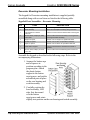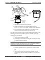
1
Crestron C2N/C2NI-CB Series ® Cameo Keypads Operations & Installation Guide This document was prepared and written by the Technical Documentation department at: Crestron Electronics, Inc. 15 Volvo Drive Rockleigh, NJ 07647 1-888-CRESTRON The specific patents that cover Crestron products are listed at patents.crestron.com. Crestron, the Crestron logo, Cameo, Cresnet, Crestron Toolbox, D3 Pro, SIMPL+, SystemBuilder, and VT Pro-e are either trademarks or registered trademarks of Crestron Electronics, Inc. in the United States and/or other countries. Windows is a trademark or registered trademark of Microsoft Corporation in the United States and/or other countries. Other trademarks, registered trademarks, and trade names may be used in this document to refer to either the entities claiming the marks and names or their products. Crestron disclaims any proprietary interest in the marks and names of others. Crestron is not responsible for errors in typography or photography. This document was written by the Technical Publications department at Crestron. ©2014 Crestron Electronics, Inc. Crestron C2N/C2NI-CB Series Cameo Keypads Contents Cameo Keypads: C2N/C2NI-CB Series 1 Introduction ...................................................................................... 1 Features and Functions .......................................................... 1 Specifications ......................................................................... 3 Physical Description .............................................................. 4 Industry Compliance.............................................................. 7 Setup................................................................................................. 9 Network Wiring ..................................................................... 9 Identity Code ....................................................................... 10 Assembly and Installation ................................................... 12 Programming Software .................................................................. 23 Earliest Version Software Requirements for the PC .................. 23 Programming with Crestron SystemBuilder or D3 Pro .......... 24 Programming with SIMPL Windows .................................. 25 Uploading and Upgrading .............................................................. 29 Communication Settings...................................................... 29 Uploading a SIMPL Windows Program.............................. 32 Firmware Upgrade ............................................................... 35 Problem Solving............................................................................. 38 Troubleshooting ................................................................... 38 Further Inquiries .................................................................. 38 Future Updates ..................................................................... 39 Appendix: Template for Flush Mounting Hole ............................. 40 Return and Warranty Policies ........................................................ 41 Merchandise Returns / Repair Service ................................ 41 CRESTRON Limited Warranty .......................................... 41 Operations & Installation Guide - DOC. 6346C Contents • i Crestron C2N/C2NI-CB Series Cameo Keypads Cameo Keypads: C2N/C2NI-CB Series Introduction Features and Functions The Crestron® C2N/C2NI-CB Series Cameo® keypads are a new generation of wall-mounted user interfaces that can be part of any Crestron total solution control system network (Cresnet®). The keypads are available in three versions: C2N-CBF, Flush Mount (no back box required) for domestic and international installation; C2N-CBD, Standard Mount (decorator style), back box installation, for domestic installation; and C2NI-CBUK, Standard Mount, optional UK-style back box, for UK installation. For maximum flexibility in all configurations, a complete set of button caps and spacers in three sizes is included with every keypad. The installer can customize and configure the backlit caps, for “rocker” left/right action, single press operation, or press and hold mode—up to 18 functions in total. Functional Summary • Six switches, each programmable for left/right “rocker” action, single press operation, or press/hold mode, enabling up to 18 functions • Button caps and spacers supplied in single-, two-, and threebutton configurations—any combination may be used • LED feedback and switch backlighting intensity are individually programmable • Exclusive flush-mount, decorator style, or traditional mounting installation Operations & Installation Guide - DOC. 6346C Cameo Keypads: C2N/C2NI-CB Series • 1 Cameo Keypads Crestron C2N/C2NI-CB Series The basic Cameo keypad colors are black, white, and almond. The keypad’s colors and finishes can be used to accent a home’s colors, wall coverings, or décor. Additional designer colors are available. (Contact a Crestron customer service representative for details.) Mounting options include a choice of installation as a standalone device using Crestron’s exclusive flush-mounting system; or, for the domestic keypads, decorator installation in a conventional gang-box using standard decorator style faceplates; or for the UK-style models, traditional mounting (electrical box optional). The flush-mounting system is the ultimate low-profile appearance that results in a footprint that is up to 75% smaller than a standard decorator style faceplate, and blends into any room effortlessly. Refer to Assembly and Installation procedures, on page 12, for details. Each Cameo keypad is supplied with single-row button caps, double-row button caps, and triple-row button caps as well as two single-row spacers, one double-row spacer, and one triple-row spacer. All switches on the keypad are functionally identical. White feedback LEDs to the left of each row are independently addressable and indicate which switches are active. The intensity of the feedback LEDs is programmable from 0 to 100%. Button caps have white LED backlighting that is programmable from 0 to 100% intensity as well. In certain circumstances, such as when using black button caps, true backlighting is not practical. Instead, the program can use the feedback LEDs to perform a backlighting function, turning them all on but at a fixed percentage of their active state intensity. For programming details, refer to “Cameo Symbol in Programming Manager,” on page 27. 2 • Cameo Keypads: C2N/C2NI-CB Series Operations & Installation Guide - DOC. 6346C Crestron C2N/C2NI-CB Series Cameo Keypads Specifications The following table summarizes the specifications of the keypads. Specifications for the Keypads SPECIFICATION Cresnet Power Usage Default Net ID Control System Update Files 1, 2, 3 2-Series Control System CNMSX-AV/PRO CNRACKX/-DP CEN/CN-TVAV ST-CP C2N-CB-Series Firmware Environmental Temperature Humidity Overall Dimensions: Flush Mount Model Decorator Style Model UK Style Model Weight 1. 2. 3. 4. DETAILS 3 Watts (0.125 Amps @ 24 VDC) 25 Version 2.004.CUZ or later Version 5.14.02X.UPZ or later Version 5.14.02W.UPZ or later Version 5.12.63V.UPZ or later Version 4.02.4S.UPZ or later C2N-CB.v2.10.upg or later 32° to 113°F (0° to 45°C) 10% to 90% RH (non-condensing) Height: 3.20 in (8.13 cm) Width: 1.73 in (4.38 cm) Depth: 1.52 in (3.86 cm)4 Height: 4.12 in (10.47 cm) Width: 1.80 in (4.56 cm) Depth: 1.52 in (3.86 cm)4 Height: 3.38 in (8.58 cm) Width: 3.38 in (8.58 cm) Depth: 1.52 in (3.86 cm)4 2.6 oz (73 g) – Flush mount 3.1 oz (87 g) – Decorator style 2.5 oz (70 g) – UK Style The latest versions can be obtained from the Crestron website. Refer to NOTE after last footnote. Crestron 2-Series control systems include the AV2 and PRO2. Consult the latest Crestron Product Catalog for a complete list of 2-Series control systems. Filenames for CNX and ST-CP update files have a UPZ extension. Files on the website may be .zip or self-extracting .exe files containing the .cuz or .upz file. All can be obtained from the Downloads section of the Crestron website. To avoid program problems, make sure you are using the update file with the correct suffix letter (e.g., S, V, W, X). The depth of the Keypad is listed without the Cresnet connector (approximately 0.45 in) or clearance for the wiring. NOTE: Crestron software and any files on the website are for Authorized Crestron dealers and Crestron Authorized Independent Programmers Operations & Installation Guide - DOC. 6346C Cameo Keypads: C2N/C2NI-CB Series • 3 Cameo Keypads Crestron C2N/C2NI-CB Series (CAIP) only. New users may be required to register to obtain access to certain areas of the site (including the FTP site). Physical Description Active switches and spacers can be mixed and arranged as needed to suit a particular application. LEDs along the side of the keypad identify the active switches. Each keypad has a mini Cresnet network port labeled 24 Y Z G. The port provides for operating power and for communication to/from the keypad. The button caps are tapered and are arranged in a shingle style with the narrow part of the button cap at the top. Each button cap can, however, be arranged in either orientation, and the overall keypads can be installed with the LEDs on the right. Spacers are flat and flush with the front of the bezel surface. Button caps are laser-engravable using the Crestron Engraver software; spacers are not. The engraving software provides up to three fields for each button cap to allow for the left/right and center press functions, permits multiple lines of text, and also allows you to specify the orientation of each button cap. The Crestron Engraver software, Version 2.4 or later, is available from the Crestron website. NOTE: A single button cannot be installed in the lowest position of the keypad. The following illustrations provide overall dimensions of the three keypad styles. 4 • Cameo Keypads: C2N/C2NI-CB Series Operations & Installation Guide - DOC. 6346C Crestron C2N/C2NI-CB Series Cameo Keypads Keypad Overall Dimensions – Flush Mount Configuration 1.73 in (4.38 cm) 1.52 in (3.86 cm) 3.20 in (8.13 cm) Operations & Installation Guide - DOC. 6346C Cameo Keypads: C2N/C2NI-CB Series • 5 Cameo Keypads Crestron C2N/C2NI-CB Series Keypad Overall Dimensions – Decorator Mount Configuration 1.52 in (3.86 cm) 1.80 in (4.56 cm) 4.12 in (10.47 cm) 6 • Cameo Keypads: C2N/C2NI-CB Series Operations & Installation Guide - DOC. 6346C Crestron C2N/C2NI-CB Series Cameo Keypads Keypad Overall Dimensions – UK-Style Configuration 1.14 in (2.89 cm) 1.52 in (3.86 cm) 0.30 in (0.76 cm) 3.38 in (8.58 cm) 3.38 in (8.58 cm) Industry Compliance As of the date of manufacture, the keypads have been tested and found to comply with specifications for CE marking. NOTE: This device complies with part 15 of the FCC rules. Operation is subject to the following two conditions: (1) this device may not cause harmful interference, and (2) this device must accept any interference received, including interference that may cause undesired operation. Operations & Installation Guide - DOC. 6346C Cameo Keypads: C2N/C2NI-CB Series • 7 Cameo Keypads Crestron C2N/C2NI-CB Series This equipment has been tested and found to comply with the limits for a Class B digital device, pursuant to part 15 of the FCC Rules. These limits are designed to provide reasonable protection against harmful interference in a residential installation. This equipment generates, uses and can radiate radio frequency energy and if not installed and used in accordance with the instructions, may cause harmful interference to radio communications. However, there is no guarantee that interference will not occur in a particular installation. If this equipment does cause harmful interference to radio or television reception, which can be determined by turning the equipment off and on, the user is encouraged to try to correct the interference by one or more of the following measures: Reorient or relocate the receiving antenna. Increase the separation between the equipment and receiver. Connect the equipment into an outlet on a circuit different from that to which the receiver is connected. Consult the dealer or an experienced radio/TV technician for help. 8 • Cameo Keypads: C2N/C2NI-CB Series Operations & Installation Guide - DOC. 6346C Crestron C2N/C2NI-CB Series Cameo Keypads Setup Network Wiring CAUTION: In order to ensure optimum performance over the full range of your installation topology, Crestron Certified Wire, and only Crestron Certified Wire, should be used. Failure to do so may incur additional charges if support is required to identify performance deficiencies as a result of using improper wire. CAUTION: Use only Crestron power supplies for Crestron equipment. Failure to do so could cause equipment damage or void the Crestron warranty. CAUTION: Provide sufficient power to the system. Insufficient power can lead to unpredictable results or damage to the equipment. Please use the Crestron Power Calculator to help calculate how much power is needed for the system (http://www.crestron.com/calculators). When calculating the length of wire for a particular Cresnet run, the wire gauge and the Cresnet power usage of each network unit to be connected must be taken into consideration. Use Crestron Certified Wire only. If Cresnet units are to be daisy-chained on the run, the Cresnet power usage of each network unit to be daisy-chained must be added together to determine the Cresnet power usage of the entire chain. If the unit is a home-run from a Crestron system power supply network port, the Cresnet power usage of that unit is the Cresnet power usage of the entire run. The wire gauge and the Cresnet power usage of the run should be used in the following equation to calculate the cable length value on the equation’s left side. Cable Length Equation L< 40,000 RxP Where: L = Length of run (or chain) in feet. R = 6 Ohms (Crestron Certified Wire: 18 AWG (0.75 MM2)) P = Cresnet power usage of entire run (or chain). Make sure the cable length value is less than the value calculated on the right side of the equation. For example, a Cresnet run drawing 20 watts should not have a length of run more than 333 feet. Operations & Installation Guide - DOC. 6346C Cameo Keypads: C2N/C2NI-CB Series • 9 Cameo Keypads Crestron C2N/C2NI-CB Series NOTE: All Crestron certified Cresnet wiring must consist of two twisted pairs. One twisted pair is the +24V conductor and the GND conductor, and the other twisted pair is the Y conductor and the Z conductor. NOTE: When daisy-chaining Cresnet units, strip the ends of the wires carefully to avoid nicking the conductors. Twist together the ends of the wires that share a pin on the network connector, and tin the twisted connection. Apply solder only to the ends of the twisted wires. Avoid tinning too far up the wires or the end becomes brittle. Insert the tinned connection into the Cresnet connector and tighten the retaining screw. Repeat the procedure for the other three conductors. NOTE: For larger networks (i.e., greater than 28 network devices), it may become necessary to add a Cresnet Hub/Repeater (CNXHUB) to maintain signal quality throughout the network. Also, for networks with lengthy cable runs, it may be necessary to add a Hub/Repeater after only 20 devices. Identity Code Every equipment and user interface within the network requires a unique identity code (Net ID). These codes are two-digit hexadecimal numbers from 03 to FE. (Net ID 02 is reserved for master control units). The Net IDs reside within all Cresnet devices (hardware) and must match the Net ID as specified in the software (SIMPL Windows) that runs the system. Refer to “Setting the Net ID in Device Settings” on page 27 for details of the SIMPL Windows procedure. The Net ID of the keypad has been factory set to 25. The Net IDs of multiple keypads in the same system must be unique. Net IDs are changed from a personal computer (PC) via the Crestron Toolbox™. NOTE: For detailed information on establishing communication between the PC and control system, refer to “Communication Settings” on page 29. If communication cannot be established, refer to the “Troubleshooting Communications” section in the latest version of the 2-Series Control System Reference Guide (Doc. 6256), or the respective Operations Guide for the control system. Both are available at http://www.Crestron.com/manuals. 10 • Cameo Keypads: C2N/C2NI-CB Series Operations & Installation Guide - DOC. 6346C Crestron C2N/C2NI-CB Series Cameo Keypads The Crestron Toolbox provides several methods to easily set or change device Net IDs for any device on the network. The following method permits you to change the Net ID of any device in the network through the “Network Device Tree” window. NOTE: This method prevents you from setting duplicate IDs. This method lets you manually set the Net ID for any device in the network, can be used to set any known Net IDs that require changing, and may also be used for non-TSID equipment. This method will not permit you to choose an ID already in use by another device. A warning message will appear if you attempt to use an ID that is already in use. Duplicate Net ID Warning Message This method does not change the Net ID as assigned in SIMPL windows. Refer to page 27 for the SIMPL Windows ID change procedure. NOTE: You may also use SystemBuilder to perform Network ID setup. 1. Connect all network devices to the control system. 2. Open Crestron Toolbox and establish communications (refer to page 29). 3. Select the Network Device Tree Network Device Tree View. icon, or select Tools | Network Device Tree 4. Right-click on the device Net ID, and when the sub-menu appears, select Change Network ID from the sub-menu. Operations & Installation Guide - DOC. 6346C Cameo Keypads: C2N/C2NI-CB Series • 11 Cameo Keypads Crestron C2N/C2NI-CB Series Network Device Tree – Sub-Menu 5. Enter a new Net ID and press Enter. Enter New Net ID 6. Repeat this procedure for each additional network device requiring a Net ID change. Assembly and Installation Assembly of the keypad consists of placing the button caps/spacers in position based on how the unit is programmed, securing them together with a plastic button support, putting the button cap/spacer assembly in place on the rear housing and switch assembly, and attaching the bezel. The button caps are tapered, and are often installed in a shingle-style pattern (refer to the “Keypad Overall Dimensions – Flush Mount Configuration ” illustration on page on page 5). Usual orientation of the keypad is with the LEDs on the left. It can, however, be inverted with the LEDs on the right, but the original relationship of the button numbers to the LEDs remains, i.e., with the unit inverted, row one is on the bottom – 12 • Cameo Keypads: C2N/C2NI-CB Series Operations & Installation Guide - DOC. 6346C Crestron C2N/C2NI-CB Series Cameo Keypads row six is on the top, and programming of the switches would have to be done accordingly. Installation consists of connecting the unit to the Cresnet system, and then mounting it directly to the mounting surface or to a back box, depending on the keypad configuration. The following items are required for all installations: • Cresnet network cable (not supplied) • No. 2 Phillips screwdriver (not supplied) Flush Mounting Installation The Cameo keypad for flush mounting installation is supplied partially assembled along with several items as listed in the following table. Supplied Parts/Assemblies – Flush Mounting QTY ITEM DESCRIPTION 1 Rear housing and switch assembly Rear housing with switch circuitry attached 1 Bezel Bezel assembly 1 4-pin female mini network connector Used to connect Cresnet network cable to the keypad 2 Screws, Black, Phillips pan head, 4-40 x 3/16” Used to attach the bezel assembly to the keypad rear housing and switch assembly 1 Double row spacer Switch cover for two non-operational switches 1 Triple row spacer Switch cover for three non-operational switches 1 Plastic button support Used to hold the button caps/spacers together in position 1 Spring clamp Used to secure the assembled keypad in the wall 1 Template Used to mark correct hole size in the wall Assemble the keypad as described in the following steps. Refer to the accompanying illustrations. 1. Place the button caps and/or spacers in position according to the program plan. Attach the plastic button support to the button caps/spacers, and put the assembled parts in place on the rear housing and switch assembly. (Refer to the illustration for the standard mounting installation procedures, step 1, on page 16.) 2. Carefully position the bezel assembly, LED edge first, down and over the button caps/blanks and rotate slightly into position on the rear housing and switch assembly. Operations & Installation Guide - DOC. 6346C Cameo Keypads: C2N/C2NI-CB Series • 13 Crestron C2N/C2NI-CB Series Cameo Keypads 3. Hold the bezel and rear housing together and install and tighten the two supplied Phillips pan head, 4-40 x 3/16” cover screws (black) into the rear housing and switch assembly, as shown in the following illustration. 4. Press each button to be certain that you feel the press and release to ensure that the button caps move freely. LED Holes Bezel Button Caps and Spacers Cover Screw Plastic Button Support LEDs Rear Housing and Switch Assembly 5. Attach the spring clamp to the rear of the keypad, as shown in the following figure, by loosening the screws sufficiently to place the clamp over the screws and slide it down into position, and then retighten the screws. Spring Clamp 14 • Cameo Keypads: C2N/C2NI-CB Series Loosen Screws Operations & Installation Guide - DOC. 6346C Crestron C2N/C2NI-CB Series Cameo Keypads 6. Use the supplied template to prepare the hole in the wall. (Refer to the Appendix on page 40 for an illustration of the template.) After the Cresnet network wiring has been installed and verified, use the following procedure to install the keypad in the prepared hole. NOTE: Be very careful when cutting the hole. There are no adjustments for alignment with the spring clamp. 7. Connect the Cresnet cable, using the supplied mating connector, to the keypad’s Cresnet port. 8. Make sure the keypad is oriented properly and insert the keypad in the hole. The natural action of the spring clamp holds the keypad in position. Slot 9. Turn Cresnet system power ON. 10.If the keypad needs to be removed from the wall, there is a slot on one edge of the bezel (refer to the figure). Use a small flat blade screwdriver to pry the keypad away from the wall, being careful to avoid damage to the wall surface, and use your fingers to remove the keypad. Operations & Installation Guide - DOC. 6346C Cameo Keypads: C2N/C2NI-CB Series • 15 Crestron C2N/C2NI-CB Series Cameo Keypads Decorator Mounting Installation The keypad for Decorator mounting installation is supplied partially assembled along with several items as listed in the following table. Supplied Parts/Assemblies – Decorator Mounting QTY ITEM DESCRIPTION 1 Rear housing and switch assembly Rear housing with switch circuitry attached 1 Bezel assembly Bezel and metal plate assembly, with ground wire 1 4-pin female mini network connector Used to connect Cresnet network cable to the keypad 2 Screws, Black, Phillips pan head, 4-40 x 3/16” Used to attach the bezel assembly to the keypad rear housing and switch assembly 2 Single row spacer Switch cover for single non-operational switch 1 Double row spacer Switch cover for two non-operational switches 1 Triple row spacer Switch cover for three non-operational switches 1 Plastic button support Used to hold the button caps/spacers together in position 2 Screws, Steel, Phillips, pan head, 6-32 x 7/8” Used to attach the assembled keypad to a back box Assemble the keypad as described in the following steps. Refer to the accompanying illustrations. 1. Arrange the button caps and/or spacers in position according to the program plan. Attach the plastic button support to the button caps/spacers, and put the assembled parts in place on the rear housing and switch assembly. 2. Carefully position the bezel assembly, LED edge first, down and over the button caps/spacers and rotate slightly into position on the rear housing and switch assembly. 16 • Cameo Keypads: C2N/C2NI-CB Series Operations & Installation Guide - DOC. 6346C Crestron C2N/C2NI-CB Series LED Holes Cameo Keypads Bezel Assembly Button Caps and Spacers Ground Wire Cover Screw Plastic Button Support LEDs Bracket Rear Housing and Switch Assembly 3. Hold the bezel and rear housing together 4. Install and tighten the two supplied Phillips pan head, 4-40 x 3/16” cover screws (black), as shown in the illustration. 5. Press each button to be certain that you feel the press and release to ensure that the button caps move freely. After the Cresnet network wiring has been installed and verified, use the following procedure to install the keypad in a standard, single-gang electrical box (not supplied). 1. Turn Cresnet system power OFF. 2. Connect the Cresnet cable to the keypad’s Cresnet port, using the supplied mating connector. CAUTION: Excess wire pinched between the keypad and electrical box could short out. Make sure that all excess wire is completely inside the electrical box and not between the box and the keypad. 3. Attach the ground wire to the ground screw of the electrical box. 4. Make sure the keypad is oriented properly, place it in the electrical box, and attach using the supplied 7/8 in. pan head screws. Operations & Installation Guide - DOC. 6346C Cameo Keypads: C2N/C2NI-CB Series • 17 Crestron C2N/C2NI-CB Series Cameo Keypads 5. Attach the desired decorator style faceplate (not supplied). 6. Turn the Cresnet system power ON. UK-Style Mounting Installation The keypad for UK-style mounting installation is supplied partially assembled along with several items as listed in the following table. Supplied Parts/Assemblies – UK-Style Mounting QTY ITEM DESCRIPTION 1 Rear housing and switch assembly Rear housing with switch circuitry attached 1 Bezel Bezel assembly 1 Plastic wall plate Alternate mounting device and bezel support 1 4-pin female mini network connector Used to connect Cresnet network cable to the keypad (Continued on next page) 18 • Cameo Keypads: C2N/C2NI-CB Series Operations & Installation Guide - DOC. 6346C Crestron C2N/C2NI-CB Series Cameo Keypads Supplied Parts/Assemblies – UK-Style Mounting (continued) QTY ITEM DESCRIPTION 2 Screws, Black, Phillips pan head, 4-40 x 3/16” Used to attach the bezel assembly to the keypad rear housing and switch assembly 2 Single row spacer Switch cover for single non-operational switch 1 Double row spacer Switch cover for two non-operational switches 1 Triple row spacer Switch cover for three non-operational switches 2 Screws, Steel, Phillips, pan head, 6-32 x 7/8” Used only to attach assembled keypad to back box Assemble the keypad as described in the following steps. Refer to the accompanying illustration. 1. Place the button caps and/or spacers in position according to the program plan. Attach the plastic button support to the button caps/spacers, and put the assembled parts in place on the Rear Housing and Switch assembly. (Refer to the illustration for the standard mounting installation procedures, step 1, on page 16.) 2. Carefully position the bezel assembly, LED edge first, down and over the button caps/blanks and rotate slightly into position on the rear housing and switch assembly. 3. Hold the bezel and rear housing together and install and tighten the two supplied Phillips pan head, 4-40 x 3/16” cover screws (black), as shown in the illustration. Bezel LED Holes Button Caps and Spacers LEDs Cover Screw Plastic Button Suport Rear Housing and Switch Assembly 4. Press each button to be certain that you feel the press and release to ensure that the button caps move freely. Operations & Installation Guide - DOC. 6346C Cameo Keypads: C2N/C2NI-CB Series • 19 Cameo Keypads Crestron C2N/C2NI-CB Series The keypad can be mounted directly to a mounting surface or it can be mounted to a back box. In both cases, you can choose to have mounting screws visible or hidden. Mounting to the Mounting Surface Use the supplied template to prepare the hole in the wall. (Refer to the Appendix on page 40 for an illustration of the template.) After the Cresnet network wiring has been installed and verified, use the following procedure to install the keypad in the prepared hole. 1. Put the plastic wall plate in position over the prepared hole and attach using two screws (not supplied) appropriate for the mounting surface. (Refer to A in the figure on page 22.) 2. Turn Cresnet system power OFF, and connect the Cresnet cable to the keypad’s Cresnet port, using the supplied mating connector. 3. Insert the keypad into the hole and press the bezel against the plastic wall plate until it snaps securely into position. 4. Turn the Cresnet system power On. If the keypad needs to be removed from the wall, there are two slots on one edge of the bezel (visible in the figure on page 22). Use a flat blade screwdriver to pry the bezel away from the wall plate, being careful to avoid damage to the bezel. Mounting to a UK-Style Back Box Prepare the hole in the wall appropriate for the back box. (Back boxes for these keypads are typically square or rounded and have tabs with screw holes for mounting the keypads on each side rather than top and bottom.) After the Cresnet network wiring has been installed and verified, use the following procedure to install the keypad in the back box. 1. Put the plastic wall plate in position over the back box and attach using the supplied 7/8 in. pan head screws. (Refer to B in the figure on page 22.) 2. Turn Cresnet system power OFF, and connect the Cresnet cable to the keypad’s Cresnet port, using the supplied mating connector. 20 • Cameo Keypads: C2N/C2NI-CB Series Operations & Installation Guide - DOC. 6346C Crestron C2N/C2NI-CB Series Cameo Keypads 3. Insert the keypad into the hole and press the bezel against the plastic wall plate until it snaps securely into position. 4. Turn the Cresnet system power On. If the keypad needs to be removed from the wall, there are two slots on one edge of the bezel (visible in the figure on page 22). Use a flat blade screwdriver to pry the bezel away from the wall plate, being careful to avoid damage to the bezel. Mounting Using Screws Through the Bezel Refer to the figure on the next page and do the following. 1. Drill pilot holes through the bezel from the rear at each of the drill center points. Then, from the front of the bezel, drill the final holes and countersink as required. (Refer to C in the figure on page 22.) 2. Place the plastic wall plate over the keypad with the smooth surface facing out, and snap the wall plate and bezel together. 3. Attach the keypad to the mounting surface or to the back box using the appropriate screws. 4. Turn the Cresnet system power On. If the keypad needs to be removed from the wall, remove the screws securing the keypad to the mounting surface/back box, and pull the keypad free. Operations & Installation Guide - DOC. 6346C Cameo Keypads: C2N/C2NI-CB Series • 21 Crestron C2N/C2NI-CB Series Cameo Keypads A B Screws (not supplied) Plastic Wall Plate C2NI-CBUK C Screws (supplied) Plastic Wall Plate Back Box (typical) Bezel (Rear View) Drill Centerpoint (2) 22 • Cameo Keypads: C2N/C2NI-CB Series Operations & Installation Guide - DOC. 6346C Crestron C2N/C2NI-CB Series Cameo Keypads Programming Software Have a question or comment about Crestron software? Answers to frequently asked questions (FAQs) can be viewed in the Online Help section of the Crestron website. To post a question or view questions you have submitted to Crestron’s True Blue Support, log in at http://support.crestron.com. First-time users will need to establish a user account. You can create a program that allows you to include the Cameo keypad in a Crestron control system using the Crestron programming tools Crestron SystemBuilder™ or D3 Pro® and SIMPL Windows. These tools are intended for users with different levels of programming knowledge. The flexibility of each tool is proportional to the degree of programming expertise (i.e., the more flexible, the more a programmer needs to know and account for). Of course, one can initiate programming using the easiest method (SystemBuilder or D3 Pro) and use advanced techniques that are available from SIMPL Windows to customize the job. Earliest Version Software Requirements for the PC NOTE: Crestron recommends that you use the latest software to take advantage of the most recently released features. The latest software is available from the Crestron website. The following are the earliest useable software version requirements for the PC: • SIMPL Windows version 2.06.20 or later, plus Library Update 352. Requires the following software versions: o SIMPL+® Cross Compiler version 1.1. o Crestron Database version 17.3.3 or later. Operations & Installation Guide - DOC. 6346C Cameo Keypads: C2N/C2NI-CB Series • 23 Crestron C2N/C2NI-CB Series Cameo Keypads • (Optional) SystemBuilder version 2.0 or later with SystemBuilder Templates version 2.0.1or later. Requires the following software versions: o PC with Windows 2000 or XP o SIMPL Windows version 2.06.20 or later with library update file 352 or later. Requires SIMPL+ Cross Compiler version 1.1. o Crestron database 17.3.3 or later o Vision Tools Pro-e 3.3.4.0 or later o Crestron Toolbox 1.01.11 or later • o Engraver 2.5 or later (Optional) D3 Pro version 2.0 or later with D3 Pro Templates 1.0 or later. Requires the following software versions: o PC with Windows 2000 or XP o SIMPL Windows version 2.06.20 or later with library update file 352 or later. o Crestron database 17.3.3 or later o Vision Tools Pro-e 3.3.4.0 or later o Crestron Toolbox 1.01.11 or later o Engraver 2.5 or later o CUZ 3.137 for 2-Series processors or later • Crestron Engraver version 2.5 (required if using SystemBuilder or to produce custom labeling for the buttons). The easiest method of programming, but does not offer as much flexibility as SIMPL Windows. Programming with Crestron SystemBuilder or D3 Pro Crestron SystemBuilder offers automatic programming for such residential and commercial applications as audio distribution, home theater, video conferencing, and lighting. The interface of this tool guides you through a few basic steps for designating rooms and specifying the control system, touchpanels, devices, and functionality. Crestron SystemBuilder then programs the system, including all touchpanel projects and control system logic. 24 • Cameo Keypads: C2N/C2NI-CB Series Operations & Installation Guide - DOC. 6346C Crestron C2N/C2NI-CB Series Cameo Keypads Crestron D3 Pro similarly offers automatic programming for lighting, HVAC, and security. Both Crestron SystemBuilder and D3 Pro are fully integrated with Crestron's suite of software development tools, including SIMPL Windows, VT Pro-e, and the Crestron Database. Both access these tools behind the scenes, enabling you to easily create robust systems. Programming with SIMPL Windows NOTE: The following assumes that the reader has knowledge of SIMPL Windows. If not, refer to the extensive help information provided with the software. NOTE: In the following description, the PRO2 control system is used. SIMPL Windows is Crestron's software for programming Crestron control systems. It provides a well-designed graphical environment with a number of workspaces (i.e., windows) in which a programmer can select, configure, program, test, and monitor a Crestron control system. SIMPL Windows offers drag and drop functionality in a familiar Windows environment. This section describes a sample SIMPL Windows program that includes a Cameo keypad. Configuration Manager is where programmers “build” a Crestron control system by selecting hardware from the Device Library. In Configuration Manager, drag the PRO2 from the Control Systems folder of the Device Library and drop it in the upper pane of the System Views. The PRO2 with its associated communication ports is displayed in the System Views upper pane. PRO2 System View The System Views lower pane displays the PRO2 system tree. This tree can be expanded to display and configure the communications ports. Operations & Installation Guide - DOC. 6346C Cameo Keypads: C2N/C2NI-CB Series • 25 Cameo Keypads Crestron C2N/C2NI-CB Series Expanded PRO2 System Tree C2Net-Device Slot in Configuration Manager To incorporate a Cameo keypad into the system, drag the C2N-CB from the Wired Keypad folder of the Device Library and drop it in System Views. The PRO2 system tree displays the C2N-CB in Slot 9, with a default Net ID of 25 as shown in the following illustration. C2Net Device, Slot 9 NOTE: The first Cameo keypad in a system is preset with a net ID of 25 when its symbol is dragged into the upper pane of System Views. Additional units are assigned different numbers as they are added. 26 • Cameo Keypads: C2N/C2NI-CB Series Operations & Installation Guide - DOC. 6346C Crestron C2N/C2NI-CB Series Cameo Keypads Setting the Net ID in Device Settings Double-click the C2N-CB icon in the upper pane to open the “Device Settings” window. This window displays C2N-CB device information. Select the Net ID tab to change the Net ID, as shown in the following figure. C2N-CB Device Settings Window NOTE: This procedure sets the Net ID for the C2N-CB in the program only. It does not automatically set the Net ID for the keypad itself. NOTE: SIMPL Windows automatically changes Net ID values of a device added to a program if a duplicate device or a device with the same Net ID already exists in the program. Always ensure that the hardware and software settings of the Net ID match. For Net ID hardware setting details, refer to “Identity Code” on page 10. Cameo Symbol in Programming Manager Programming Manager is where programmers “program” a Crestron control system by assigning signals to symbols. For detailed information, refer to the SIMPL program help file (F1). Button Locations The following illustration demonstrates the available button locations, available left (L), right (R), and center (C) button press options, and feedback LEDs on the keypad. Operations & Installation Guide - DOC. 6346C Cameo Keypads: C2N/C2NI-CB Series • 27 Crestron C2N/C2NI-CB Series Cameo Keypads Cameo Keypad Button and Feedback LED Arrangement Feedback 1 (fbck1) Feedback 6 (fbck6) L C R Button Location 1 L C R Button Location 2 L C R Button Location 3 L C R Button Location 4 L C R Button Location 5 L C R Button Location 6 Reverse Button Locations In cases where it is desirable to mount the keypad with the feedback LEDs on the right, programmers will have to take into account that physically, button 6 is now at the top, button 1 is at the bottom, and that the right and left switch positions are reversed. Bear in mind, however, that when combining buttons in this orientation, the usual programming constraints still apply. For example, if merging buttons 4, 5, and 6, even though button 6 is now physically at the top of the keypad, button 4 still controls the mode of the merged buttons. NOTE: A Crestron module in Crestron Database version 17.1.0, the C2N-Cameo Bargraph Feedback v1.0, makes it possible to use the feedback LEDs like a bargraph, so that for a function like volume control, as the switches are used to control the volume, the LEDs display its approximate level. An example program for the Cameo keypad is available from the “Example Program” section of the Crestron website (http://www.crestron.com/exampleprograms). Search for C2N-CB Example Program (ZIP). 28 • Cameo Keypads: C2N/C2NI-CB Series Operations & Installation Guide - DOC. 6346C Crestron C2N/C2NI-CB Series Cameo Keypads Uploading and Upgrading NOTE: Crestron recommends that you use the latest software and that each device contains the latest firmware to take advantage of the most recently released features. Please check the Crestron website (http://www.crestron.com/updates) for the latest versions of software and firmware. New users are required to register to obtain access to this site. Assuming a PC is properly connected to the entire system, Crestron programming software allows the programmer to upload programs to the control system after their development and firmware upgrades to network devices. However, there are times when the files for the program are compiled and not uploaded. Instead, compiled files may be distributed from programmers to installers, from Crestron to dealers, etc. Even firmware upgrades are available from the Crestron website as new features are developed after product releases. In those instances, one has the option to upload via the programming software or to upload and upgrade via the Crestron Toolbox. The following sections define how one would upload a SIMPL Windows program or upgrade the firmware of the Cameo keypad. However, before attempting to upload or upgrade, it is necessary to establish communications. Communication Settings NOTE: For laptops and other PCs without a built-in RS-232 port, Crestron recommends the use of a PCMCIA card over a USB adapter, particularly if using Viewport. The procedure in this section provides details for RS-232 communication between the PC and the control system. If TCP/IP communication is preferred, consult the latest version of the Crestron e-Control Reference Guide (Doc. 6052) or the respective Operations Guide for the control system. These documents are available from the Crestron website. Refer to the following figure for a typical connection diagram when uploading files. NOTE: Use a standard DB9 male to female “straight-through” cable. Operations & Installation Guide - DOC. 6346C Cameo Keypads: C2N/C2NI-CB Series • 29 Crestron C2N/C2NI-CB Series Cameo Keypads Typical Connection Diagram when Uploading 1. Open Crestron Toolbox and click Tools | Manage Address Book to display a list of available devices. Select Serial on COM1 as the connection type. Serial on COM1 is an entry in the DefaultAddressBook that is included with Crestron Toolbox. The PC communication settings specified here should match the protocol that the control processor expects. The usual settings are as follows: • Port = COM 1 through COM 8. Select the correct COM port on the PC. • Baud rate = Auto-detect. • Parity = None. • Number of data bits = 8. • Number of stop bits = 1. • Hardware handshaking (RTS/CTS) enabled. • Software handshaking (XON/XOFF) not enabled. 30 • Cameo Keypads: C2N/C2NI-CB Series Operations & Installation Guide - DOC. 6346C Crestron C2N/C2NI-CB Series Cameo Keypads “Address Book” Window – Serial Setup 2. After setting the correct parameters, click OK to return to the Crestron Toolbox main window. 3. Click Tools | Network Device Tree View, or click the network to display the devices in the system. Select device tree icon Serial on COM1 from the drop down list if it is not already selected. If communication is successful, the network devices that are connected to the control system are displayed. Network Device Tree To view a specific device, expand the network device tree by clicking the +. Expand the network device tree till the device to be Operations & Installation Guide - DOC. 6346C Cameo Keypads: C2N/C2NI-CB Series • 31 Crestron C2N/C2NI-CB Series Cameo Keypads managed is selected. Right-click the desired Net ID to open the sub-menu. This menu provides a wide range of operations, including; change the Net ID, open text console, and, through the sub-sub menu, additional functions such as updating firmware and serial number conversion. Network Device Tree Sub-Menu -Functions NOTE: Toolbox displays a customized list of functions depending on the type of device with which it is communicating. A control . system source file has the extension .smw. A compiled SIMPL Windows file has the extension .spz for a 2-Series control system, .bin for CNX generation, and .csz for CNX generation with SIMPL+. Uploading a SIMPL Windows Program The SIMPL Windows file can be uploaded to the control system using SIMPL Windows or via the Crestron Toolbox. Upload via SIMPL Windows 1. Start SIMPL Windows. 2. Select File | Open to view the “Open” window, navigate to the SIMPL Window file (.smw), and click Open. 3. Select Project | Transfer Program. Upload via Crestron Toolbox 1. Verify that the procedure for “Communication Settings” that begins on page 29 has been performed. 32 • Cameo Keypads: C2N/C2NI-CB Series Operations & Installation Guide - DOC. 6346C Crestron C2N/C2NI-CB Series Cameo Keypads 2. Open Crestron Toolbox. 3. Select Tools | System Info. Crestron Toolbox – Tools | System Info 4. When the “System Info” window appears and you are connected to the control system, the Functions option becomes available from the menu bar. 5. Select Functions | SIMPL Program. The “SIMPL Program” window contains information about the currently loaded SIMPL program (if any), and permits you to stop, start, erase, retrieve, and upload a SIMPL program. This menu also permits you to upload to compact flash or internal flash. Operations & Installation Guide - DOC. 6346C Cameo Keypads: C2N/C2NI-CB Series • 33 Cameo Keypads Crestron C2N/C2NI-CB Series “SIMPL Program” Window 6. Click the Browse button to browse for a new compiled (.spz) program file in the “Open” window. “Open” Window 34 • Cameo Keypads: C2N/C2NI-CB Series Operations & Installation Guide - DOC. 6346C Crestron C2N/C2NI-CB Series 7. A firmware upgrade file has the extension .upg. Cameo Keypads Select a file and click Open. When the “SIMPL Program” window re-opens click Send. Firmware Upgrade To take advantage of all the Cameo keypad features, it is important that the unit contains the latest firmware available. Please check the Crestron website for the latest version of firmware. Not every product has a firmware upgrade, but as Crestron improves functions, adds new features, and extends the capabilities of its products, firmware upgrades are posted. To upgrade the firmware, complete the following steps. 1. Make sure that “Communication Settings” that begins on page 29 has been performed. 2. Open Crestron Toolbox. 3. Open the Network Device Tree (the firmware upgrade function is also available in the SMW Program Tree window). 4. Right-click on the device and select Functions | Firmware. Network Device Tree Window – Right-Click Sub Menu 5. The “Firmware” window displays the model and current firmware version. Operations & Installation Guide - DOC. 6346C Cameo Keypads: C2N/C2NI-CB Series • 35 Crestron C2N/C2NI-CB Series Cameo Keypads “Firmware” Window 6. Click Browse to display the Open window to locate the desired firmware (.upg) file. Locate Firmware in the “Open” Window 7. Click Open to return to the “Firmware” window, and click Send to transfer the file. The File Transfer window monitors the transfer of the file and gives you the option of canceling the transfer. 36 • Cameo Keypads: C2N/C2NI-CB Series Operations & Installation Guide - DOC. 6346C Crestron C2N/C2NI-CB Series Cameo Keypads “File Transfer” Window 8. When the transfer is complete, the “Firmware” window reopens indicating the new firmware version. Click Close after the firmware has been transferred. Operations & Installation Guide - DOC. 6346C Cameo Keypads: C2N/C2NI-CB Series • 37 Crestron C2N/C2NI-CB Series Cameo Keypads Problem Solving Troubleshooting The table below provides corrective action for possible trouble situations. If further assistance is required, please contact a Crestron customer service representative. Keypad Troubleshooting TROUBLE POSSIBLE CAUSE(S) CORRECTIVE ACTION The keypad does not function. The wrong power supply is being used. Use a Crestron power supply. The unit is not receiving power, or is receiving insufficient power. Verify that the cable plugged into the NET port is secure. Verify that the power supply is correct. There is a loose connection in the network. Verify that the cable plugged into the NET port is secure. The keypad does not function. All six feedback LEDs are on low. Improper Net ID used. Verify that the Cameo Net ID matches the Net ID in the software program. Keypad does not function, or does not function as expected. However, it reports on Cresnet at the proper Net ID. Not programmed correctly Use Test Manager to check the behavior when buttons are pressed. Revise and reload the program as needed to correct the behavior. Further Inquiries If you cannot locate specific information or have questions after reviewing this guide, please take advantage of Crestron's award winning customer service team by calling the Crestron corporate headquarters at 1-888-CRESTRON [1-888-273-7876]. For assistance in your local time zone, refer to the Crestron website (http://www.crestron.com/) for a listing of Crestron worldwide offices. You can also log onto the online help section of the Crestron website to ask questions about Crestron products. First-time users will need to establish a user account to fully benefit from all available features. 38 • Cameo Keypads: C2N/C2NI-CB Series Operations & Installation Guide - DOC. 6346C Crestron C2N/C2NI-CB Series Cameo Keypads Future Updates As Crestron improves functions, adds new features, and extends the capabilities of the Cameo keypad, additional information and programming examples may be made available as manual updates. These updates are solely electronic and serve as intermediary supplements prior to the release of a complete technical documentation revision. Check the Crestron website periodically for manual update availability and its relevance. Updates are identified as an “Addendum” in the Download column. Operations & Installation Guide - DOC. 6346C Cameo Keypads: C2N/C2NI-CB Series • 39 Crestron C2N/C2NI-CB Series Cameo Keypads Appendix: Template for Flush Mounting Hole The following figure (not to scale) illustrates the supplied template used to prepare the hole in the wall or other mounting surface for the flush mounting style Cameo keypad. NOTE: Use only the original template, not a photocopy, to prepare the hole. Photocopies usually alter the size of the image slightly, which would make the hole the wrong size. Be careful when cutting the hole, the spring clamp on the keypad does not have provision for positioning adjustment. Also, ensure that there is a sufficient clearance area behind the mounting surface as shown on the template. 5.38 in (13.66 cm) (5 3/8 in) 3.68 in (9.34 cm) (3 11/16 in) 2.68 in (6.80 cm) (2 11/16 in) 1.38 in (3.50 cm) (1 3/8 in) 2.38 in (6.04 cm) (2 3/8 in) 3.32 in (8.42 cm) (8 27/64 in) 40 • Cameo Keypads: C2N/C2NI-CB Series Operations & Installation Guide - DOC. 6346C Crestron C2N/C2NI-CB Series Cameo Keypads Return and Warranty Policies Merchandise Returns / Repair Service 1. No merchandise may be returned for credit, exchange, or service without prior authorization from CRESTRON. To obtain warranty service for CRESTRON products, contact an authorized CRESTRON dealer. Only authorized CRESTRON dealers may contact the factory and request an RMA (Return Merchandise Authorization) number. Enclose a note specifying the nature of the problem, name and phone number of contact person, RMA number, and return address. 2. Products may be returned for credit, exchange, or service with a CRESTRON Return Merchandise Authorization (RMA) number. Authorized returns must be shipped freight prepaid to CRESTRON, 6 Volvo Drive, Rockleigh, N.J., or its authorized subsidiaries, with RMA number clearly marked on the outside of all cartons. Shipments arriving freight collect or without an RMA number shall be subject to refusal. CRESTRON reserves the right in its sole and absolute discretion to charge a 15% restocking fee, plus shipping costs, on any products returned with an RMA. 3. Return freight charges following repair of items under warranty shall be paid by CRESTRON, shipping by standard ground carrier. In the event repairs are found to be non-warranty, return freight costs shall be paid by the purchaser. CRESTRON Limited Warranty CRESTRON ELECTRONICS, Inc. warrants its products to be free from manufacturing defects in materials and workmanship under normal use for a period of three (3) years from the date of purchase from CRESTRON, with the following exceptions: disk drives and any other moving or rotating mechanical parts, pan/tilt heads and power supplies are covered for a period of one (1) year; touch screen display and overlay components are covered for 90 days; batteries and incandescent lamps are not covered. This warranty extends to products purchased directly from CRESTRON or an authorized CRESTRON dealer. Purchasers should inquire of the dealer regarding the nature and extent of the dealer's warranty, if any. CRESTRON shall not be liable to honor the terms of this warranty if the product has been used in any application other than that for which it was intended, or if it has been subjected to misuse, accidental damage, modification, or improper installation procedures. Furthermore, this warranty does not cover any product that has had the serial number altered, defaced, or removed. This warranty shall be the sole and exclusive remedy to the original purchaser. In no event shall CRESTRON be liable for incidental or consequential damages of any kind (property or economic damages inclusive) arising from the sale or use of this equipment. CRESTRON is not liable for any claim made by a third party or made by the purchaser for a third party. CRESTRON shall, at its option, repair or replace any product found defective, without charge for parts or labor. Repaired or replaced equipment and parts supplied under this warranty shall be covered only by the unexpired portion of the warranty. Except as expressly set forth in this warranty, CRESTRON makes no other warranties, expressed or implied, nor authorizes any other party to offer any warranty, including any implied warranties of merchantability or fitness for a particular purpose. Any implied warranties that may be imposed by law are limited to the terms of this limited warranty. This warranty statement supercedes all previous warranties. Operations & Installation Guide - DOC. 6346C Cameo Keypads: C2N/C2NI-CB Series • 41 Crestron C2N/C2NI-CB Series Cameo Keypads This page intentionally left blank. 42 • Cameo Keypads: C2N/C2NI-CB Series Operations & Installation Guide - DOC. 6346C Crestron C2N/C2NI-CB Series Cameo Keypads This page intentionally left blank. Operations & Installation Guide - DOC. 6346C Cameo Keypads: C2N/C2NI-CB Series • 43 Crestron Electronics, Inc. 15 Volvo Drive Rockleigh, NJ 07647 Tel: 888.CRESTRON Fax: 201.767.7576 www.crestron.com Operations & Installation Guide - DOC. 6346C (2012599) 03.14 Specifications subject to change without notice.