1
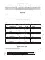
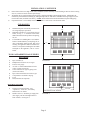
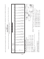
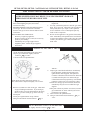
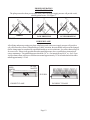
BLUE FLAME
VENT FREE HEATERS
INSTALLATION AND
OPERATION INSTRUCTIONS
P/N 88950 / REV. MARCH 2013
R
TYPE GAS
NATURAL GAS
PROPANE GAS
MODEL NUMBERS
BFT101
BFT102
BFT201
BFT202
BFT301
BFT302
WARNING: If the information in this manual is not
followed exactly, a fire or explosion may result causing
property damage, personal injury, or loss of life.
•
•
•
•
Do not store or use gasoline or other flammable vapors and liquids in the vicinity of this
or any other appliance.
WHAT TO DO IF YOU SMELL GAS:
Do not try to light any appliance.
Do not touch any electrical switch; do not use any
phone in your building.
Immediately call your gas supplier from a neighbor’s
phone. Follow the gas supplier’s instructions.
If you cannot reach your gas supplier, call the fire
department.
-
INSTALLATION AND SERVICE MUST BE
PERFORMED BY A QUALIFIED
INSTALLER, SERVICE AGENCY OR THE
GAS SUPPLIER.
INSTALLER: Leave this manual
with the appliance.
CONSUMER: Retain this
manual for future reference.
INSTALLER MUST SHOW
HOMEOWNER PROPER
LIGHTING AND OPERATION
OF HEATER. HAVE THEM
COMPLETE AND RETURN
THE WARRANTY CARD.
This is an unvented gas fired heater. It uses air (oxygen) from the room in which it is installed. Provisions
for adequate combustion and ventilation air must be provided. See Pg. 4 & 5.
This unit is for residential use only and is not approved for installation in greenhouses,or
environments involving dusty, wet, corrosive, or explosive conditions. Such conditions will
invalidate the warranty and may create unsafe conditions.
This appliance may be installed in an aftermarket, permanently located, manufactured (mobile) home,
where not prohibited by local codes. This appliance is only for use with the type of gas indicated on the
rating plate. This appliance is not convertible for use with other gases.
Installation, maintenance, service, troubleshooting and repairs must be performed by a qualified service
agency. MR./MRS. HOMEOWNER, DO NOT attempt any of these procedures yourself as this could
expose you to property damage, personal injury or loss of life and will invalidate all warranties.
WARNING: Improper installation, adjustment, alteration, service or maintenance can cause property
damage, personal injury or loss of life. Refer to the owner’s information manual provided with this
appliance. Installation and service must be performed by a qualified installer, service technician or the
gas supplier.
The State of Massachusetts requires that installation and service of a gas
appliance be performed by a plumber or gas fitter licensed in the
Commonwealth of Massachusetts.
HEATERS INSTALLED ABOVE 4,500 FT. MAY EXPERIENCE NUISANCE PILOT
OUTAGE AND THIS CONDITION MAY BE AGGRAVATED BY IMPROPER GAS
SUPPLY PRESSURE AND/OR INCORRECT SIZING RELATIVE TO FREE AIR OR
CONFINED SPACE.
CONTENT
INTRODUCTION……………………….
SPECIFICATIONS………………………
SAFETY INSTRUCTIONS……………..
FRESH AIR FOR COMBUSTION VENTILATION & AIR DISTRIBUTION…….
INSTALLATION………………………..
CLEARANCES………………………….
TOOLS & ADDITIONAL SUPPLIES…..
GAS ROUGH-IN…………………………
WALL MOUNT………………………….
FREE STANDING……………………….
2, 3
3
3, 4
4, 5
5, 6
6
6
6
9
9
GAS CONNECTION…………………………….
LIGHTING INSTRUCTIONS…………………….......
PROPER OPERATION………………………….........
MAINTENANCE………………………………..........
BLOWER INSTRUCTIONS…………………….........
TROUBLE SHOOTING GUIDE………………...........
ILLUSTRATED PARTS BREAKDOWN……….......
PARTS LIST……………………………………..........
WARRANTY…………………………………............
L.P. GAS WARNING SHEET…………….........…….
10
11
12
13
14
15
16
17
18
19
INTRODUCTION
Read these installation and operating instructions carefully before you install or attempt to use this vent free
room heater. If you do not understand any part of these instructions, consult local authorities, a qualified
installer, service agency, or the gas supplier. FAILURE TO READ OR UNDERSTAND THESE
INSTRUCTIONS CAN RESULT IN MALFUNCTION, INEFFICIENT OPERATION,
PROPERTY DAMAGE, SERIOUS INJURY OR DEATH.
These installation instructions are a general guide and do not supersede applicable local codes and
ordinances. Before planning or beginning the installation be sure it complies with all phases of the local
heating code. Or, in the absence of local codes, with the latest edition of the National Fuel Gas Code,
ANSI.Z223.1. A copy of which is available from the American Gas Association, 1515 Wilson Blvd.,
Arlington, Virginia 22209.
The design of this appliance was certified to comply with the latest edition of ANSI Z21.11.2, also available
from the American Gas Association.
Page 2
INTRODUCTION – CONT’D.
For your protection this heater is equipped with an Oxygen Depletion Sensor (ODS) pilot system. Never operate heater if
ODS has been damaged or tampered with as this could expose you to Carbon Monoxide (a colorless, odorless gas) that
could result in injury or death. Early signs of Carbon Monoxide poisoning resemble influenza, with headaches, dizziness,
or nausea. If you develop these symptoms GET FRESH AIR AT ONCE. Turn off heater and call a qualified serviceman to
check heater. Some people are more affected by Carbon Monoxide than others: Including pregnant women, persons with
a heart or lung disease, anemia, those under the influence of alcohol, and those at high altitudes.
OPERATION
The Cozy thermostatically controlled units offer the additional benefit of automatically cycling the heating to maintain just
the right room temperature. VENTFREE GAS ROOM HEATERS ARE DESIGNED STRICTLY FOR “SUPPLEMENTAL”
ROOM HEAT USE AND SHOULD NEVER BE INSTALLED AS “SOLE SOURCE HEATING”.
ROOM HEATER SPECIFICATIONS
Your room heater comes packed in a single carton. Before installation, check the rating plate to verify that the Model
Number is correct and that the room heater is equipped for the type gas you intend to use.
MODEL NO./NAT.
MODEL NO./L.P.
BFT101
BFT102
BFT201
BFT202
BFT301
BFT302
Control
Height
T-Stat Bulb
22-1/2”
T-Stat Bulb
22-1/2”
T-Stat Bulb
22-1/2”
Width
Depth
14-9/16”
7”
20-11/16”
7”
26-13/16”
7”
Max. Input BTU hr.
Min. Input BTU Hr.
10,000
6,000
20,000
10,000
30,000
20,000
Gas Supply Line Size
Optional Blower
1/2”
No
1/2”
Yes
1/2”
Yes
Optional Floor Stand
Bathroom Installation
Yes
No
Yes
No
Yes
No
Bedroom Installation
Piezo Ignitor
Yes
Yes
No
Yes
No
Yes
Shipping Weight
22 Lbs.
32 Lbs.
35 Lbs.
SAFETY INSTRUCTIONS
1)
2)
3)
4)
5)
6)
Keep burner and control compartment clean.
Due to high temperatures, the heater should be located out of traffic and away from furniture and draperies.
Children and adults should be alerted to the hazard of high surface temperature and should stay away to avoid burns
or clothing ignition.
Young children should be carefully supervised then they are in the same room with this heater.
Do not place clothing or other flammable material on or near the heater.
Any safety screen or guard removed for servicing must be replaced prior to operating the heater.
Page 3
SAFETY INSTRUCTIONS - CONTINUED
7)
8)
9)
10)
11)
12)
13)
14)
15)
16)
17)
18)
19)
20)
Installation and repair should be done by a qualified technician. The heater should be inspected before use and
at least annually by a professional service technician. More frequent cleaning may be required due to excessive
lint from carpeting, bedding, material, etc. It is imperative that control compartments, burners, and circulating air
passageways of the heater be kept clean.
“WARNING: Any modifications to this heater or its controls can be dangerous”.
Do not use this heater if any part has been under water. Immediately call a qualified service technician to inspect
the heater and to replace any part of the control system and any gas control which has been under water.
Due to high surface temperatures, keep children, clothing, and furniture away.
Do not install this heater in a recreational vehicle.
Never use a match, candle, flame or other source of ignition to check for gas leaks. Use only soapy water or
liquid detergent.
Before cleaning or servicing, turn off the gas and allow heater to cool.
Do not put objects around the heater that will obstruct the flow of combustion and ventilation air.
When installing the heater allow adequate accessibility clearances for servicing and proper operation.
Keep appliance area clear and free from combustible materials, gasoline and other flammable vapors and liquids.
Do not install in a residential or commercial garage.
WARNING: Do not use a blower or other accessory not approved for use with this heater.
WARNING: Failure to keep the primary air opening(s) of the burner(s) clean may result in sooting and property
damage.
This appliance is intended for supplemental heating.
FRESH AIR FOR COMBUSTION, VENTILATION AND HEAT DISTRIBUTION
With todays energy efficient homes, it is possible to make your home so air tight that it can result in stale air, dry rot, mold
development and host of other related problems. Gas burning appliances need fresh air for combustion as well as for
good distribution of heated air throughout the home. The following guide provides good general rules for classifying and
properly ventilating most homes.
“This heater shall not be installed in a confined or unusually tight construction unless provisions are provided for
adequate combustion and ventilation air.”
“This heater shall not be installed in a room or space unless the required volume of indoor combustion air is provided by
the method described in the National Fuel Gas Code, ANSI Z223.1/NFPA 54, the International Fuel Gas Code, or
applicable local codes.”
“WARNING: If the area in which the heater may be operated does not meet the required volume for indoor combustion
air, combustion and ventilation air shall be provided by one of the methods described in the National Fuel Gas Code,
ANSI Z223.1/NFPA 54, the International Fuel Gas Code, or applicable local codes.”
“A confined space is a space whose volume is less than 50 ft³ per 1000 Btu/hr (4.8 m³ per kw) of the aggregate input
rating of all appliances installed in that space and an unconfined space as a space whose volume is not less than 50 ft³
per 1000 Btu/hr (4.8 m³ per kw) of the aggregate input rating of all appliances installed in that space. Rooms communicating directly with the space in which the appliances are installed, through openings not furnished with doors, are
considered a part of the unconfined space.”
Use the following example to determine if the heater is being installed in a confined or unconfined space.
STEP 1. First find the cubic feet of area to be heated length x width x height. NOTE: Include any adjoining rooms that
cannot be separated by closing a door or that have a air exchange grille that cannot be closed between rooms.
EXAMPLE: Area size 25 ft. x 15 ft. x 7-1/2 ft. = 2,812.5 cubic feet.
STEP 2. Divide area cubic feet by 50. EXAMPLE: 2,812.5 ÷ 50 = 56.25. Multiply this number by 1,000 for total Btu input
room can support. E XAMPLE: 56.25 x 1,000 = 56,250 Btu.
STEP 3. List all gas burning appliances in this area and total the combined Btu input. EXAMPLE:
Cozy vent free heater……………………..
20,000 Btu
Gas water heater…………………………..
58,000 Btu
Gas range (all burners & oven on)………..
28,000 Btu
106,000 Btu
Page 4
FRESH AIR FOR COMBUSTION, VENTILATION AND HEAT DISTRIBUTION - CONT’D.
STEP 4. Compare the total Btu the area can support (from Step 2) to the total Btu in the area the heater will be installed
(from Step 3). If the total from Step 2 is larger this is considered an unconfined space, if Btu total from Step 3 is larger this
is considered a confined space and provisions must be made for additional combustion and ventilation air. EXAMPLE:
Btu area can support is 56,250, total Btu in area is 106,000 – this would be a confined space.
NOTE: A third construction class is one with unusually tight construction, defined as, construction where: (A) Walls
and ceilings exposed to the outside atmosphere have a continuous water vapor retarder with a rating of 1 per (6x10-11 Kg
per pa-sec-m²) or less with openings gasketed or sealed, and, (B) Weatherstripping has been added enable windows and
doors, and , (C) Caulking or sealants are applied to areas such as joints around window and door frames, between sole
plates and floors, between wall ceiling joints, between wall panels, at penetration for plumbing, electrical, and gas lines,
and at other openings.
“WARNING: If the area in which the heater may be operated does not meet the required volume for indoor combustion
air, combustion and ventilation air shall be provided by one of the methods described in the National Fuel Gas Code,
ANSI Z223.1/NFPA 54 Air for Combustion and Ventilation, the International Fuel Gas Code, or applicable local codes.”
Examples would be to provide two permanent openings either to an adjoining room, or to the outside. See the National
Fuel Gas Code for details. See Figure 9 & Figure 10 below.
Chimney or gas vent
Chimney or gas vent
Ventilation louvers
(each end of attic)
Opening
Outlet Air
Furnace Water
Heater
Alternate
air inlet
Opening
Equipment located in confined
spaces; all air from inside the
building. See 5.3.3(a).
Furnace Water
Heater
Inlet Air
Ventilation louvers for
unheated crawl space
Equipment located in confined spaces; all air from
outdoors - inlet air from ventilated crawl space and
outlet air to ventilated attic. See 5.3.3(b).
FIGURE 9
FIGURE 10
INSTALLATION
Installation and service must be performed by a qualified installer, service technician or the gas supplier.
LOCATION
1)
2)
For most efficient performance, locate heater as centrally as possible in the area to be heated.
Do not install heater in a closet, alcove or small hallway where the heater could be isolated from the space to be
heated and adequate combustion air by closing a door.
Page 5
INSTALLATION - CONTINUED
3)
4)
5)
Protect heater from wind, high traffic areas, and drafts (such as doorways, locations that get direct air from a ceiling
fan, etc.) as this will cause nuisance pilot outage.
All models may be wall mounted using the factory supplied (standard) wall mounting bracket. Additionally all
models may be installed freestanding, by adding the optional VF-FSK Floor Stand Kit and using an approved, fire
resistant floor mat (available from factory). NOTE: Both wall and floor mount installations require hard piping.
If optional blower is to be added, locate heater so there is safe access to an electrical outlet.
CLEARANCES
1)
2)
3)
Maintain adequate accessibility clearances for
servicing and proper operation.
Minimum clearances as viewed from front of
heater, see Fig. 1. 3” clearance below heater
shall be measured from top surface of carpeting,
tile, etc.
If VF-FSK Free Standing Kit is used and the
heater is installed directly on carpeting, tile, or
other combustible material other than wood
flooring, the appliance shall be installed on a
metal or wood panel extending the full width
and depth of the appliance, such as a stove
board.
36”
6”
TOOLS AND ADDITIONAL SUPPLIES
REQUIRED
1)
2)
3)
4)
5)
6)
7)
8)
9)
Pipe wrenches (2).
Phillip head screwdriver or screwgun.
Pressure test gauge.
An A.G.A. certified manual shut off valve
with 1/8” NPT pressure tap.
Union connector for type of piping used
(check local codes).
Pipe sealant certified for use with L.P. gas.
Components to assemble a drip leg.
Level.
Drill (if anchors are required).
6”
3”
FIGURE 1
ROUGH-IN GAS SUPPLY
1)
2)
Determine location of heater. (See
“Operation”, “Fresh Air”, and “Safety
Instructions” for details.
Install at least a ½” diameter gas supply line.
(Gas supply can enter through bottom or
back of heater). See Figure 2.
1-5/8”
GAS INLET LOCATION
FIGURE 2
Page 6
13-1/16”
Page 7
Internal
Diameter,
Inches 10
43
0.364
95
0.493
175
0.622
360
0.824
680
1.049
1400
1.38
2100
1.61
3950
2.067
6300
2.469
11000
3.068
23000
4.026
20
29
65
120
250
465
950
1460
2750
4350
7.7
15800
30
24
52
97
200
375
770
1180
2200
3520
6250
12800
40
20
45
82
170
320
660
990
1900
3000
5300
10900
60
16
36
66
138
260
530
810
1520
2400
4300
8800
70
15
33
61
125
240
490
750
1400
2250
3900
8100
80
14
31
57
118
220
460
690
1300
2050
3700
7500
90
13
29
53
110
205
430
650
1220
1950
3450
7200
26
Feet
125
11
24
44
93
175
360
550
1020
1650
2950
6000
Second Stage
Regulator
First Stage
Regulator
100
12
27
50
103
195
400
620
1150
1850
3250
6700
58
Feet
175
9
20
37
77
145
300
460
850
1370
2450
5000
Furnace
200,000
Water
Heater
38,000
150
10
22
40
84
160
325
500
950
1500
2650
5500
Clothes
Dryer
35,000
200
8
19
35
72
135
280
430
800
1280
2280
4600
Range
65,000
Total second stage piping length = 58 feet (use table 4, @ 60 feet).
From a to b, demand = 338,000 BTU/hr; use 1” pipe.
From b to c, demand = 138,000 BTU/hr; use ¾” pipe or 7/8” tubing.
From c to d, demand = 100,000 BTU/hr; use ½” pipe or ¾” tubing.
From d to e, demand = 35,000 BTU/hr; use ½” pipe or ½” tubing.
From b to f, demand = 200,000 BTU/hr; use ¾” pipe.
From c to g, demand = 38,000 BTU/hr; use ½” pipe or 5/8” tubing.
From d to h, demand = 65,000 BTU/hr; use ½” pipe or 5/8” tubing.
Total first stage piping length = 26 feet; first stage regulator setting is 10 PSIG (use Table 1 or 3,
@ 30 feet)
From aa to a, demand = 338,000 BTU/hr; use ½” pipe, ½” tubing, or ½” T plastic pipe.
50
18
40
73
151
285
580
900
1680
2650
4750
9.7
LENGTH OF PIPE, FEET
*Information from - REGO PRODUCTS
“LP GAS SERVICEMAN’S MANUAL”
SEE FOLLOWING PAGE FOR PIPE SIZING CHARTS FOR PROPANE GAS.
Total piping length = 84 feet (use table 4 @ 90 feet)
From a to b, demand =200,000 + 38,000 +65,000+35,000
= 338,000 BTU/hr. use 1” pipe.
From b to c, demand = 38,000 + 65,000 + 35,000
= 138,000 BTU/hr; use ¾” pipe or 7/8” tubing.
From c to d, demand = 65,000 + 35,000
= 100,000 BTU/hr; use ¾” pipe or ¾” tubing.
From d to e, demand = 35,000 BTU/hr; use ½” pipe or 5/8” tubing.
From b to f, demand = 200,000 BTU/hr; use 1” pipe.
From c to g, demand = 38,000 BTU/hr; use ½” pipe or 5/8” tubing.
From d to h, demand = 65,000 BTU/hr; use ½” pipe or ¾” tubing.
Example 2.
Determine the sizes of piping or tubing required for the two-stage L.P.
Gas installation shown.
* Pipe and Tubing Selection
Nominal
Iron Pipe
Size,
Inches
¼
3/8
½
¾
1
1-1/4
1-1/2”
2
2-1/2
3
4
(Based on a 0.60 Specific Gravity Gas)
Maximum Capacity of Pipe in Cubic Feet of Gas per Hour for Gas Pressures of 0.5 psig or Less and a Pressure Drop of 0.5 Inch Water Column.
NATURAL GAS
SEE FOLLOWING CHARTS FROM NFPN54, ANSI Z223.1 TO DETERMINE PROPER GAS SUPPLY LINE SIZE REQUIRED TO SUPPORT TOTAL BTU REQUIREMENTS.
TABLE 1 – first stage pipe sizing
PROPANE GAS
10 PSIG Inlet with a 1 PSIG Pressure Drop
Maximum capacity of pipe or tubing, in thousands of BTU/hr. of L.P. Gas
Size of Pipe
Or Copper
Tubing, Inches
Copper
Tubing
(O.D.)
Pipe
Size
Copper
Tubing
(O.D.)
Pipe
Size
LENGTH OF PIPE OR TUBING, FEET*
10
20
30
40
50
60
70
80
90
100
3/8
½
5/8
¾
½
¾
1
1-1/4
1-1/2
2
558
1387
2360
3993
3339
6982
13153
27004
40461
77924
383
870
1622
2475
2295
4799
9040
18560
27809
53556
309
700
1303
2205
1843
3854
7259
14904
22331
43008
265
599
1115
1887
1577
3298
6213
12756
19113
36809
235
531
988
1672
1398
2923
5507
11306
16939
32623
213
481
896
1515
1267
2649
4989
10244
15348
29559
196
443
824
1394
1165
2437
4590
9424
14120
27194
182
412
767
1297
1084
2267
4270
8767
13136
25299
171
386
719
1217
1017
2127
4007
8226
12325
23737
161
365
679
1149
961
2009
3785
7770
11642
22422
3/8
½
5/8
¾
½
¾
1
1-1/4
1-1/2
2
125
142
323
601
1018
852
1780
3354
6887
10318
19871
150
130
293
546
923
772
1613
3039
6240
9349
18005
175
118
269
502
843
710
1484
2796
5741
8601
16564
200
111
251
467
790
660
1381
2601
5340
8002
15410
225
104
235
438
740
619
1296
2441
5011
7508
14459
250
90
222
414
700
585
1224
2305
4733
7092
13658
275
89
211
393
664
556
1162
2190
4495
6735
12971
300
89
201
375
634
530
1109
2089
4289
6426
12375
350
82
185
345
584
488
1020
1922
3945
5911
11385
400
76
172
321
543
454
949
1788
3670
5499
10591
*Total length of piping from outlet of first stage regulator to inlet of second stage regulator (or to inlet of second stage regulator furthest
away).
Notes:
1) To allow 2 PSIG pressure drop, multiply total gas demand by .707, and use capacities from table.
2) For different first stage pressures, multiply total gas demand by the following factors, and use capacities from table.
First State Pressure PSIG
Multiply by
20
.844
21
.912
Data Calculated per NFPA #54 & 58.
TABLE 4 – Second, Single, or Integral Twin Stage Pipe Sizing
11 Inches Water Column Inlet with a ½ Inch Water Column Drop
Maximum capacity of pipe or tubing in thousands of BTU/hr of LP-Gas
Size of Pipe
Or Copper
Tubing, Inches
Copper
Tubing
(O.D.)
Pipe
Size
Copper
Tubing
(O.D.)
Pipe
Size
PROPANE GAS
LENGTH OF PIPE OR TUBING, FEET*
10
20
30
40
50
60
70
80
90
100
3/8
1/2
5/8
3/4
7/8
1/2
3/4
1
1-1/4
1-1/2
2
49
110
206
348
536
291
608
1146
2353
3525
6789
34
76
141
239
368
200
418
788
1617
2423
4666
27
61
114
192
296
161
336
632
1299
1946
3747
23
52
97
164
253
137
287
541
1111
1665
3207
20
46
86
146
224
122
255
480
985
1476
2842
19
42
78
132
203
110
231
435
892
1337
2575
—
38
71
120
185
102
212
400
821
1230
2369
—
36
67
113
174
94
198
372
764
1144
2204
—
33
62
105
161
87
185
349
717
1074
2068
—
32
59
100
154
84
175
330
677
1014
1954
3/8
1/2
5/8
3/4
7/8
1/2
3/4
1
1-1/4
1-1/2
2
125
—
—
—
—
—
74
155
292
600
899
1731
150
—
—
—
—
—
67
141
265
544
815
1569
175
—
—
—
—
—
62
129
244
500
749
1443
200
—
—
—
—
—
58
120
227
465
697
1343
225
—
—
—
—
—
54
113
213
437
654
1260
250
—
—
—
—
—
51
107
201
412
618
1190
275
—
—
—
—
—
48
101
191
392
587
1130
300
—
—
—
—
—
46
97
182
374
560
1078
350
—
—
—
—
—
43
89
167
344
515
992
400
—
—
—
—
—
40
83
156
320
479
923
*Total length of piping from outlet of regulator to appliance furthest away.
Page 8
Data Calculated per NFPA #54 & 58.
INSTALLING HEATER
WALL MOUNT
BFT20 & BFT30
WALL MOUNT (BFT10)
STEP 1. Remove wall mounting bracket from back of
heater.
STEP 2. Locate wall stud.
STEP 3. Attach wall mounting bracket to wall stud
with top at desired height, using (2) screws provided.
Make sure top of bracket is level. See Figure 3.
STEP 4. Hang top of heater on wall mounting bracket.
STEP 5. Remove bottom front panel.
STEP 6. Secure back of heater to wall, utilizing
anchors (if necessary) or wood screws. See Figure 4.
STEP 1. Remove wall mounting bracket from back of
heater.
STEP 2. Locate two studs.
STEP 3. Attach wall mounting bracket to wall studs with
top at desired height using (2) wood screws provided.
Make sure top of bracket is level. See Figure 5.
STEP 4. Hang top of heater over wall mounting bracket.
STEP 5. Remove bottom front panel.
STEP 6. Secure back of heater to wall, utilizing anchors (if
necessary) or wood screws. See Figure 4.
WALL STUD
WALL
MOUNTING
BRACKET
Wall Mounting Bracket
Wall Stud
FIGURE 5
INSTALLING VF-FSK FLOOR BASE KIT
FIGURE 3
STEP 1. Remove floor base from carton.
STEP 2. Align screw holes in base to holes in heater
bottom.
STEP 3. Align cut-out in bottom of heater with the cut-out
in top of floor base. The cut-out in side of floor base must
face towards the back of the heater (see illustration below).
STEP 4. Attach floor base to bottom of heater using four
#8 screws (provided).
NOTE: Floor bases are for use on BFT10, BFT20 and
BFT30.
HEATER
HOLES FOR MOUNTING BACK OF
HEATER TO WALL
FIGURE 4
Make sure this cut-out
faces back of heater.
Page 9
GAS CONNECTION
STEP 1.
Make the gas connection between the manual shut off valve and regulator located inside
heater cabinet. Hold regulator when tightening connection to prevent damage to regulator
and internal tubing. See Figure 6 for completed installation.
NOTE:
All piping and connection must be checked for leaks by the installer. If connections are not
exposed, a pressure test must be run. The appliance and its individual shut off valve must
be disconnected from the gas supply piping system during any pressure testing at pressures
in excess of ½ psig (3.5 kPa). The appliance must be isolated from the gas supply piping
system by closing its individual manual shut off valve during any pressure testing of the gas
supply piping system at test pressures equal to or less than ½ psig (3.5kPa).
Outside Reg.
Supplied
by Gas Co.
Manual
Cut off
Valve
Internal Regulator
(Supplied)
Manual Shut Off
Union
1/8” NPT
Pressure
Plug
Drip Leg
1/8” NPT Plug
Drip
Leg
GAS PIPING WITH VF-FSK KIT
FIGURE 6
FIGURE 6A
BURNER ORIFICE
This appliance is orificed at the factory for elevations up to 2,000 ft. If installed above 2,000 ft. the BTU
input must be reduced 4% per 1,000 ft. See the following orifice chart for the proper orifice for a specific
elevation. Orifice change must be done by a qualified installer or service technician.
SPECIFIC ELEVATION
Model No.
No.
0 to
2,000’
2,000 4,000’
BFT101
BFT201
BFT301
1.55 mm
43
36
54
44
38
BFT102
BFT202
BFT302
63
55
52
65
55
53
4,000 6,000 6,000’
8,000’
NATURAL GAS
54
55
45
47
40
41
L.P. GAS
65
66
56
56
53
54
Page 10
8,000 10,000’
55
48
43
68
57
54
BFT101, BFT201, BFT301 - NATURAL GAS / BFT102, BFT202, BFT302 - L.P. GAS
FOR YOUR SAFETY READ BEFORE LIGHTING
WARNING: IF YOU DO NOT FOLLOW THESE INSTRUCTIONS EXACTLY,
A FIRE OR EXPLOSION MAY RESULT CAUSING PROPERTY DAMAGE,
PERSONAL INJURY OR LOSS OF LIFE.
•
A. This appliance has a pilot which must be lighted by
hand. When lighting the pilot, follow these
instructions exactly.
B. BEFORE LIGHTING smell all around the appliance
area for gas. Be sure to smell next to the floor
because some gas is heavier than air and will settle
on the floor.
WHAT TO DO IF YOU SMELL GAS:
•
Do not try to light any appliance.
•
Do not touch any electric switch, do not use any
phone in your building.
•
Immediately call your gas supplier from a
neighbor’s phone. Follow the gas supplier’s
instructions.
If you cannot reach your gas supplier, call the fire
department.
C. Use only your hand to push in or turn the gas control
knob. Never use tools. If the knob will not push in or
turn by hand, don’t try to repair it, call a qualified
service technician. Force or attempted repair may
result in a fire or explosion.
D. Do not use this appliance if any part has been under
water. Immediately call a qualified service technician
to inspect the appliance and to replace any part of the
control system and any gas control which has been
under water.
LIGHTING INSTRUCTIONS
1.
2.
3.
STOP! Read the information on the safety label.
Depress gas control knob slightly and turn
clockwise
to “OFF”.
Turn off electric for optional blower.
Gas
Control
Knob
NOTE: Knob can not be turned from “PILOT” to
“OFF” unless knob is depressed slightly. Do not force.
4.
5.
6.
7.
“PILOT”.
Depress gas control knob and hold in. Immediately
begin alternately pushing and releasing piezo
ignitor button, observing pilot, until pilot is lit.
Continue to hold the control knob in for about one
(1) minute after the pilot is lit. Release the gas
control knob and it will pop back up. Pilot should
remain lit. If pilot goes out, repeat steps 2 thru 7.
• If knob does not pop up when released, STOP and
immediately call your service technician or gas
supplier.
• If the pilot will not stay lit after several tries, turn the
gas control knob to “OFF” and call your service
technician or gas supplier.
9. Turn on electric for optional blower.
10. Turn gas control knob counterclockwise
to
“ON”.
8.
Wait five (5) minutes to clear out any gas. Then smell
for gas, including near the floor. If you smell gas,
STOP! Follow “B” in the information on the safety
label. If you don’t smell gas, go to the next step.
Locate pilot.
Locate piezo ignitor button on top of heater.
Turn gas control knob counterclockwise
to
TO TURN OFF GAS TO APPLIANCE
1.
Depress gas control knob slightly and turn clockwise
Page 11
to “OFF”.
PROPER OPERATION
ODS / PILOT FLAME
The pilot pressure has been pre-set at the factory and with proper supply pressure will provide a safe,
reliable ignition source. See Figure 7.
CORRECT
INCORRECT LOW PRESSURE
INCORRECT - OXYGEN
LEVEL DROPPING
FIGURE 7
BURNER FLAME
All orificing and pressure setting was done at the factory and, with correct supply pressure will provide a
safe, efficient source of heat. If installed above 2,000 ft. elevation, the main burner orifice must be changed.
Orifice change must be completed by a qualified installer or service technician. See orifice chart on Page 10
for correct size. If there is any question about the manifold pressure, have a qualified serviceman check
using a manometer. The manifold pressure should be 3.0” w.c. for natural gas and 10.0” w.c. for L.P. gas.
A proper burner flame will have a soft blue outer mantel approximately 3.5 in. tall with a darker blue inner
mantel approximately 1/4” tall.
INNER
MANTEL
1/4”
OUTER
MANTEL
3-1/2”
FIGURE 8
CORRECT FLAME
INCORRECT FLAME
Page 12
MAINTENANCE
The entire heater should be checked and cleaned by a qualified service technician before the start of each
heating season. More frequent cleaning may be required due to excessive lint conditions from carpeting,
bedding material, etc.
CABINET
To clean the cabinet and hearth and jamb assemblies of your heater, turn off and allow to cool, then wipe
with a soft damp cloth. This will remove any dust. Never use metal polish, furniture wax, or any type of
cleaning solution as this could cause odors when the heater is turned back on.
MAIN BURNER
Burner may be cleaned by using a low pressure air hose, or soft brush.
ODS/PILOT
STEP 1.
Remove bottom front panel.
STEP 2.
Disconnect pilot line from pilot.
STEP 3.
Use a low pressure air hose to blow through pilot and through ODS opening in side of pilot.
WARNING: Never insert anything into any of the openings in the pilot as this could damage the Oxygen
Depletion System and expose the homeowner to Carbon Monoxide poisoning.
WARNING: After any servicing or cleaning make sure heater is completely re-assembled and check for
gas leaks.
r
Ai
y
l
p
Ap
STEP 3 - PILOT CLEANING
Page 13
BLOWER INSTRUCTIONS
INSTALLING THE VFB BLOWER (BFT201 / BFT202, BFT301 / BFT302 MODELS ONLY)
STEP 1.
STEP 2.
STEP 3.
STEP 4.
STEP 5.
STEP 6.
Remove blower assembly from shipping carton.
Insert blower assembly into upper back of heater (See Figure 11).
Secure blower to heater using three #8 screws (provided) through holes pre-punched in heater back.
Locate mounting holes for switchbox (See Figure 11).
Secure switchbox to heater using two #8 screws (provided).
Plug power cord into 115 volt three-prong grounded receptacle.
CAUTION:
Always unplug power cord before servicing or cleaning heater. This appliance is equipped with a threeprong (grounding) plug for your rotection against shock hazard and should be plugged directly into a
properly grounded three prong receptacle.
Label all wires prior to disconnection when servicing controls. Wiring errors can cause improper
and dangerous operation. Verify proper operation after servicing.
Switchbox
Blower Assembly
Blower Motor
Fan
Switch
WIRING DIAGRAM / VFB BLOWER
Page 14
Black
If any of the original wire supplied with
the appliance must be replaced, it must
be replaced with a wire of at least a
105ºC temperature rating.
White
(or ribbed)
Green
FIGURE 11
Power
Cord
TROUBLE SHOOTING GUIDE
(for use by a qualified installer or service technician)
SYMPTOM
POSSIBLE CAUSES
Ignitor wire off ODS or Piezo.
Ignitor wire shorting out on casing.
Defective piezo ignitor.
Wrong gap from electrode.
CORRECTIVE ACTION
No spark at ODS
1.
2.
3.
4.
Spark but no ignition
at ODS
1. No gas to heater.
2. Air in gas line.
3. Blocked ODS orifice.
1. Check and turn on gas.
2. Hold in pilot knob to bleed air from gas line.
3. Blow out ODS with low pressure air hose.
ODS will not remain
lit when control
knob is released
1. Safety interlock system activated.
1. Wait five minutes between re-ignition
attempts.
2. Press in control knob, light ODS and hold
control knob in for one minute.
3. Turn control knob to “OFF” then without
pushing down turn knob counterclockwise
until knob stops turning. Push
knob down completely at this point.
4. Tighten thermocouple into gas valve.
5. Replace thermocouple (hand tighten plus
1/4 turn with wrrench).
6. Replace gas valve.
7. Bleed all air from gas line.
2. Control knob not held in long
enough.
3. Control knob not in “PILOT”
position.
4. Thermocouple loose at gas valve.
5. Defective thermocouple.
6. Defective gas valve.
7. Air in line.
ODS lights but main
burner does not
1. Control knob not in “ON” position.
2. Burner orifice blocked.
3. Gas supply pressure low.
4. Weak thermocouple.
5. Defective gas valve.
Delayed ignition
1. Low gas supply pressure.
2. Burner orifice blocked.
3. Low manifold pressure.
4. ODS not in correct location.
1.
2.
3.
4.
Check and re-attach ignitor wire.
Move ignitor wire.
Replace Piezo ignitor.
Set gap at 3/16”.
1. Turn control knob to “ON”.
2. Clean burner orifice with low pressure
air hose.
3. Check supply pressure. Call gas supplier.
4. Replace ODS.
5. Replace gas valve.
1. Check supply pressure. Call gas supplier.
2. Clean burner orifice with low pressure
air hose.
3. Check and replace regulator if necessary.
4. Make sure ODS is properly mounted to
burner bracket.
Flashback
1. Improper orifice burner alignment.
2. Gas supply pressure low.
1. Correct alignment.
2. Check supply pressure. Call gas supplier.
Heater shuts off during
normal operation
1. Blocked ODS.
2. Low gas supply presure.
3. Not an adequate supply of
combustion and ventilation air.
1. Clean ODS. See maintenance section.
2. Check supply pressure. Call gas supplier.
3. See “Provisions for adequate combustion
and ventilation air” on Page 4 of
instructions.
4. Re-locate heater.
4. Heater located in drafty area.
Page 15
MODEL INCLUDED:
NAT. GAS
L.P. GAS
BFT101
BFT102
BFT201
BFT202
BFT301
BFT302
BLUE FLAME VENT FREE HEATER
PARTS LIST
Prices and specifications subject to change
without notice. All prices are F.O.B. factory.
27
26
28
25
1
23
2
24
22
20
21
3
18
4
19
17
6
29
7
8
16
14
15
9
13
ATTN: CONTRACTORS AND SERVICE TECHNICIANS,
we only sell parts through our wholesalers, but the prices
listed are for your convenience. For prompt parts service,
contact the wholesaler from which you purchased your Cozy
heater. NOTE: parts & schematic drawings on current
models are shown at www.cozyheaters.com.
Page 16
12
10
11
5
REPLACEMENT PARTS LIST. TO ORDER REPLACEMENT PARTS YOU MUST GIVE MODEL NUMBER, SERIAL
NUMBER, TYPE OF GAS USED, PART DESCRIPTION AND PART NUMBER.
MODEL NUMBERS
NAT.
L.P.
BFT101
BFT102
BFT201
BFT202
BFT301
BFT302
REF.
PART
LIST
PART
LIST
PART
LIST
PART DESCRIPTION
NO.
NO.
PRICE
NO.
PRICE
NO.
PRICE
THE PARTS LISTED BELOW WERE USED ON HEATERS WITH SERIAL NUMBERS 0216---- & 0716---(2002 & 0716 TO PRESENT.) (Check BLOCK 2 below for different parts used on 2003 through 2006).
Wall Mounting Bracket
1
35220 $
8.60
35960 $ 10.50
35960 $
10.50
Lighting Instruction Assembly
2
91373 $
3.50
91373 $
3.50
91373 $
3.50
Gas Valve 0.630.531 Nat. & L.P. (SIT)
3
88174 $ 183.90
88174 $ 183.90
88174 $ 183.90
Piezo Ignitor
4
80016 $
7.00
80016 $
7.00
80016 $
7.00
Gas Supply Tube
5
88046 $
7.50
88046 $
7.50
88046 $
7.50
Casing Right Side
6
35070 $ 16.10
35070 $ 16.10
35070 $
16.10
Regulator Support Bracket
7
35480 $
4.90
35480 $
4.90
35480 $
4.90
Right Burner Mounting Bracket
8
38090 $
3.60
38090 $
3.60
38090 $
3.60
Gas Regulator - Natural Gas
9
88029 $ 16.70
88028 $ 16.70
88028 $
16.70
Gas Regulator - L.P. Gas
9
88036 $ 21.50
88032 $ 21.50
88032 $
21.50
Main Burner Orifice - Natural Gas
10
84646 $
4.20
84639 $
4.20
84642 $
4.20
Main Burner Orifice - L.P. Gas
10
84645 $
4.20
80026 $
4.20
84644 $
4.20
Manifold
11
88500 $ 23.00
88500 $ 23.00
88500 $
23.00
Pilot Tubing Assembly
12
88013 $
5.80
88013 $
5.80
88013 $
5.80
Electrode Wire 30"
13
88070 $
3.50
88070 $
3.50
88070 $
3.50
Burner
14
88520 $ 63.40
88522 $ 66.20
88521 $
69.00
*ODS/Pilot - Natural Gas
15
88164 $ 24.90
88164 $ 24.90
88164 $
24.90
*ODS/Pilot - L.P. Gas
15
88165 $ 24.90
88165 $ 24.90
88165 $
24.90
Wire Guard
16
88501 $ 34.50
88503 $ 40.20
88502 $
46.10
Bezel Assembly
17
38050 $ 63.50
38350 $ 63.50
38550 $
63.50
Left Burner Mounting Bracket
18
38095 $
3.60
38095 $
3.60
38095 $
3.60
Bottom Front Panel
19
35360 $ 13.10
35860 $ 15.20
36360 $
17.00
Casing Back
20
35420 $ 24.90
35925 $ 24.60
36420 $
35.40
Casing Left Side
21
35060 $ 16.10
35060 $ 16.10
35060 $
16.10
Top Front Panel
22
35350 $ 13.90
35850 $ 15.50
36350 $
17.90
Blower Housing
23
N/A
N/A
37025 $ 16.00
37025 $
16.00
Blower/Motor Assembly
24
N/A
N/A
88250 $ 71.90
88250 $
71.90
Junction Box
25
N/A
N/A
37075 $
7.50
37075 $
7.50
Fan Switch
26
N/A
N/A
88240 $
7.20
88240 $
7.20
Junction Box Cover
27
N/A
N/A
37085 $
9.60
37085 $
9.60
Power Cord
28
N/A
N/A
80202 $
5.10
80202 $
5.10
Glass, Blue Flame
29
88510 $ 33.00
88512 $ 47.30
88511 $
61.80
* CURRENT ODS PILOT (88164 [NAT.] & 88165 [L.P.]) RETRO FITS ALL PILOTS. YOU MAY OR MAY NOT
NEED TO USE PART NO. 88053 3/16 COMPRESSION NUT W/FERRULE (PROVIDED).
THE PARTS LISTED BELOW WERE USED ON HEATERS WITH SERIAL NUMBERS 0316---- THROUGH 0616----.
FOR THESE OLDER HEATERS, THE PARTS LISTED BELOW ARE NEEDED FOR REPLACEMENT.
Valve, VT-23100/18, Nat. (Copreci)
Valve, VT-23100/18, L.P. (Copreci)
Manifold
Top Front Panel
3
3
11
22
88179
88179
88495
35350
$ 108.20
$ 108.20
$ 24.60
$ 13.90
88179
88179
88495
35855
$ 108.20
$ 108.20
$ 24.60
$ 23.00
88179
88179
88495
36350
$
$
$
$
108.20
108.20
24.60
17.90
ATTN: CONTRACTORS AND SERVICE TECHNICIANS, we only sell parts through our wholesalers, but the
prices listed above are for your convenience. For prompt parts service, contact the wholesaler from which you
purchased your Cozy heater. NOTE: Parts & schematic drawings on current models are shown at
www.cozyheaters.com.
Page 17
MARCH 2013
REV. 11/2007
LIMITED WARRANTY
The Louisville Tin & Stove Co. warrants to
the original user the accompanying product for the
period specified herein, provided said product is
installed, operated, maintained, serviced, and used
according to the instructions and specifications
accompanying the product.
AS OUTLINED IN
OUR INSTRUCTIONS, ANY WARRANTY
CONSIDERATIONS ARE CONTINGENT ON
INSTALLATION
BY
A
QUALIFIED
INSTALLER
(CONTRACTOR).
SELFINSTALLATION IS PROHIBITED AND WILL
INVALIDATE YOUR WARRANTY.
If within a period of one year from the date
of installation of the product, any part supplied by the
manufacturer proves to be defective due to
workmanship or material, it will replace such part,
provided parts have not been subjected to misuse,
alteration, neglect, or accidents. The term of the
warranty for the heat exchanger and burners is covered
in Table A below. Any claim not made within ten
(10) days after the expiration of the warranty period
shall be deemed waived by the user.
The manufacturer shall have no liability or
be required to perform any obligation under this
warranty unless, when requested, the user returns, at
the user’s expense, the component or product claimed
defective, to the manufacturer for inspection, to enable
the manufacturer to determine if the claimed defect is
covered by this warranty.
No charges for freight, labor or other
expenses incurred in the repair, removal, or
replacement of any product or component claimed to
be defective, will be paid by the manufacturer to the
user, and the manufacturer will not be liable for any
expenses incurred, by the user, in remedying any
defect in the product.
Service under this warranty is the
responsibility of the installer. In the event service
under this warranty is needed, the user of the product
shall request such service directly from the installer.
If the user is unable to locate the installer, the user
should write directly to the manufacturer, and the
name of an alternative service source will be supplied.
The product safety registration card (packed
inside the appliance) must be completed and returned
to the factory.
THIS WARRANTY IS EXPRESSLY IN
LIEU OF ANY OTHER WARRANTIES, EXPRESS
OR IMPLIED (WHETHER WRITTEN OR ORAL).
ANY
IMPLIED
WARRANTY
OF
MERCHANTABILITY OR OF FITNESS FOR A
PARTICULAR
PURPOSE
IS
EXPRESSLY
LIMITED TO THE DURATION OF THE
MANUFACTURER’S
EXPRESS,
WRITTEN
WARRANTY.
UNDER NO CIRCUMSTANCES SHALL
THE MANUFACTURER BE LIABLE FOR ANY
SPECIAL, INDIRECT OR CONSEQUENTIAL
DAMAGES OR EXPENSES ARISING DIRECTLY
OR INDIRECTLY FROM ANY COMPONENT OR
FROM THE USE THEREOF. THE REMEDIES SET
FORTH HEREIN SHALL BE THE EXCLUSIVE
REMEDIES AVAILABLE TO THE USER AND
ARE IN LIEU OF ALL OTHER REMEDIES.
SOME STATES DO NOT ALLOW
LIMITATIONS ON HOW LONG AN IMPLIED
WARRANTY
LASTS,
SO
THE
ABOVE
LIMITATIONS MAY NOT APPLY TO YOU.
SOME STATES DO NOT ALLOW THE
EXCLUSION OR LIMITATION OF INCIDENTAL
OR CONSEQUENTIAL DAMAGES, SO THE
ABOVE LIMITATIONS OR EXCLUSIONS MAY
NOT APPLY TO YOU.
THIS
WARRANTY
GIVES
YOU
SPECIFIC LEGAL RIGHTS, AND YOU MAY
ALSO HAVE OTHER RIGHTS, WHICH VARY,
FROM STATE TO STATE.
TABLE A
Product
Cozy Gas Fired Floor Furnace
Cozy Gas Fired Wall Furnace
Cozy Gas Fired Vented Console Heater
Cozy Gas Fired Direct Vent Heater
Cozy Gas Fired Counterflow Furnace
Cozy Gas Fired Counterflow Direct Vent Furnace
Cozy Gas Fired Mobile Home Direct Vent Furnace
Cozy Gas Fired Hi-Efficient Direct Vent Wall Furnace
Cozy Gas Fired Direct Vent Baseboard Heater
Cozy Fan-Type, Direct Vent Through-The-Wall Gas Heater
Cozy Blue Flame Vent Free Heater
Cozy Infra-Red Vent Free Heater
Warranty Period
Heat Exchanger/Tubes
Burners
10 Years
10 Years
10 Years
10 Years
10 Years
10 Years
10 Years
10 Years
10 Years
10 Years
10 Years
10 Years
10 Years
10 Years
10 Years
10 Years
10 Years
10 Years
10 Years
10 Years
N/A
10 Years
N/A
N/A
LOUISVILLE TIN & STOVE COMPANY
737 S. 13TH STREET - LOUISVILLE, KY. 40210