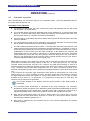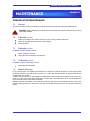
1
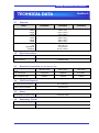
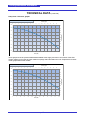
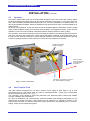
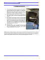
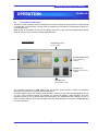
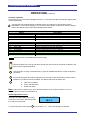
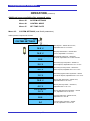
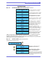
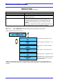
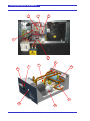
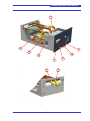
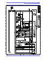
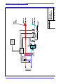
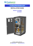
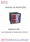
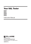
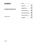
Cooling Distribution Unit Module INSTALLATION GUIDE Models: CD020W2A CD020W1A CD020W0A Coolcentric, a Division of Vette Corp 201 Boston Post Road West, Marlborough, MA 01752 Email: [email protected] Website: www.coolcentric.com Cooling Distribution Unit Module ABOUT THIS DOCUMENT Using This Document This document has been designed for viewing as a PDF file and double sided printing (subject to copyright – see below) for a hard copy. Copies of this document can be obtained from the address on the front cover. This is not a controlled document. Distributed copies will not be updated. All specifications are minimal and subject to change without prior notice as design improvements occur Copyright Notice The confidential information contained in this document is provided solely for use by the manufacturer’s employees and system owners, and is not to be released to, or produced for, anyone else. Neither is it to be used for reproduction of this unit or any of its components. All specifications are nominal and subject to change without prior notice as design improvements occur. Disclaimer The manufacturer shall not be liable for any damages resulting from mis-application or misuse of its products. E & OE GENERAL STATEMENT Product Standards Products installed and operated in accordance with instructions, conform to the EMC directive and essential Health & Safety requirements of the Machinery Directive 91/368/EEC-93/44/EEC & 93/68/EEC. This includes the EMC compatibility directive 89/336/EEC. As standard, units comply with an IP21 rating. The products are UL listed and certificates will be made available on application to the address on the front cover. CDU Module Installation Guide Page 2 Cooling Distribution Unit Module CONTENTS Section 1 1.1 1.2 1.3 1.4 1.5 1.6 1.7 1.8 1.9 SAFETY INSTRUCTIONS General Notice Installation/Handling Application Warranty Electrical connection Maintenance Service parts Codes of Practice Waste disposal Documentation 5 6 6 6 6 6 6 6 6 6 Section 2 2.1 INTRODUCTION General 7 Section 3 3.1 3.2 3.3 3.4 3.5 3.6 3.7 TECHNICAL DATA Handling Pipe Connections Electrical Connection Volume Capacity Noise Secondary Circuit Primary Circuit 9 9 9 9 9 9 11 Section 4 4.1 4.2 4.3 4.4 INSTALLATION Mechanical Electrical Hydraulic Heat Transfer Fluids 13 13 14 14 Section 5 5.1 5.2 5.3 5.4 COMMISSIONING Pre-Commissioning Checks Chilled Water Controller Setup System Filling 15 15 15 15 Section 6 6.1 6.2 6.3 6.4 6.5 OPERATION Controller Introduction Controller Menu Summary Automatic Operation Acknowledgement of Alarm Messages Control Loop set-Up 17 19 26 28 28 Section 7 7.1 7.2 7.3 7.4 7.5 PREVENTATIVE MAINTEANCE General Every 3 Months Every 6 Months Every 12 Months Module Drainage 29 29 29 29 29 Section 8 8.1 8.2 TROUBLE SHOOTING Summary of Alarm Messages Temperature Sensor Chart 31 32 Section 9 SPARE PARTS LIST 33 Section 10 10.1 10.2 DIAGRAMS Wiring Diagram Pipe Schematic 38 40 Section 11 WARRANTY & SUPPORT 41 CDU Module Installation Guide Page 3 Cooling Distribution Unit Module CDU Module Installation Guide Page 4 Cooling Distribution Unit Module SAFETY INSRUCTIONS Section 1 * * * IMPORTANT NOTICE * * * ALL PERSONNEL involved in the installation and maintenance of the Process and Ancillary Equipment, whether directly or indirectly, MUST read this notice and this complete document prior to the commencement of ANY WORK. 1. The following information must be READ, FULLY UNDERSTOOD and ADHERED to AT ALL TIMES. 2. The SAFETY of YOU and OTHER PERSONS MUST be your main concern. 3. NEVER carry out a task until you fully understand what you are being asked to do and how to do it safely. 4. NEVER carry out a task you feel could be DANGEROUS to you and other persons. 5. DO NOT carry out any task that you are not qualified to undertake. 6. ALWAYS comply with all SAFETY RULES as laid down by the relevant Authorities. 7. If you have any questions or concerns over the safety of YOU or OTHER PERSONS you MUST consult your supervisor within the Company prior to the commencement of any task. 8. NEVER start work on a unit or remove any casings, guards, doors or covers without first SWITCHING OFF and isolating the unit and controllers from the electrical supply. 9. Make sure all ROTATING PARTS commencement of any work on the unit. ARE AT REST before 10. The Safety Policy of the Company on whose premises the unit is installed should be read and understood by Maintenance Personnel. * * * ALWAYS CDU Module Installation Guide THINK Page 5 SAFETY * * * Cooling Distribution Unit Module SAFETY INSTRUCTIONS General Temperature control equipment presents mechanical, electrical, noise or vibration hazards. Observe all safety, installation, operation and maintenance instructions. Installation, servicing and operation of the equipment can only be carried out by fully trained and technically competent personnel. The Cooling Distribution Unit is designed to minimize mechanical and electrical hazards by fully restricting access through unit casings, doors and covers while equipment is operational. Some installations may require additional protective features to prevent accidental contact with components. The CDU manufacturer can provide advice and make recommendations for additional protection to suit the application. All installation work must be completed in accordance with the safety, installation, operation and maintenance instructions and the unit correctly grounded (earthed) before it is operated. Prior to any maintenance work being carried out, ensure that: Equipment is switched OFF Equipment and controls are disconnected from the electrical supply. All rotating parts have come to rest. If in any doubt as to the correct interpretation of performing the safety, installation, operation and maintenance instructions, it is essential that the CDU manufacturer, their agent or appointed distributor is consulted for advice and clarification. 1.1 Installation / Handling The installation and operation should be conducted in accordance with local regulations and accepted codes of good practice. When moving or lifting the unit, caution must be observed at all times to ensure the safety of all personnel. Only appropriate and approved lifting equipment must be used. 1.2 Application The unit must be only used in the application for which it was designed. The unit is not to be used in a hazardous environment unless it has been specially designed and approved for such application. 1.3 Warranty Failure to comply with the manufacturer’s installation instructions could affect the reliability and performance of the unit and invalidate the warranty. CDU Module Installation Guide Page 6 Warranty is subject to the implementation of a planned service/maintenance agreement - see the warranty section (Section 11) in this guide or the sales contract. 1.4 Electrical Connection The unit must be connected to an external isolator/disconnect if one is not fitted to the unit. Electrical connections should be carried out in accordance with national and local regulations. Never make any connections in the unit circuits unless the electricity supply has been switched OFF at the disconnect (isolator). 1.5 Maintenance For further information, please refer to Section 7 – Preventative and General Maintenance. 1.6 Service Parts Service parts must be of the same specification as those being renewed and should only be obtained from the CDU manufacturer. The use of incorrect service parts can affect the unit operation and reliability and invalidate any warranty. 1.7 Codes of Practice It is important that equipment and products which have been installed and commissioned are maintained by or under supervision of technical competent personnel and that all work is carried out in accordance with good engineering practice and strict adherence to: i. IEE & IEEE Standards ii. Codes of good engineering practice iii. Local Authorities iv. Statutory requirements v. Manufacturer’s instructions and recommendations vi. All other relevant information, regulations and legislation 1.8 Waste disposal Waste materials must be disposed of in a professional and responsible manner and in strict adherence to environmental regulations. For details, consult local environmental agencies. 1.9 Documentation All documentation must remain with the unit at all times. Cooling Distribution Unit Module Section 2 INTRODUCTION 2.1 General This guide describes the basic Installation, Operation and Maintenance of the Cooling Distribution Unit (CDU) and contains a detailed explanation covering the Technical Specification and Mode of Operation, description of the alarms that can be generated and the action to be taken at those alarms, a Spare Parts List and all relevant Schematic Diagrams. It is assumed that the people involved with the maintenance of this unit are familiar with basic theory and practice. Consequently only features that are of particular significance to this unit are identified. The CDU module has been designed to provide close controlled cooling water for a single IT enclosure ‘Rear Door Heat Exchanger’ (RDHx), with a total maximum cooling capacity of 20kW. The process side water (referred to as the ‘Secondary Circuit’) is a sealed pressurised system with the heat extracted from the rear door heat exchanger being rejected to a chilled water circuit. The chilled water can either be part of the Building Services Chilled Water system or from a dedicated chiller. This chilled water supply loop (referred to as the ‘Primary Circuit’) should be filtered to 300μ using a filtration unit supplied by others. Features of the CDU module include: Auto Air Vents Pressure Sensors Fill Pump Electrical compartment Level Sensor Controller Display (user interface) Secondary / Main Pump Fill Pump Connection Point View 1 CDU Module Installation Guide Page 7 Cooling Distribution Unit Module INTRODUCTION (continued) Secondary Temp Sensor Primary Temp Sensor Reservoir Tank Plate Heat Exchanger 3-Way Valve & Actuator View 2 CDU Module Installation Guide Page 8 Cooling Distribution Unit Module Section 3 TECHNICAL DATA 3.1 Physical Model: CD020W2A CD020W1A CD020W0A Cabinet dimensions: Width Height Depth 483mm (19”) 267mm (10½”) 730mm (28¾”) Width Height Depth 605mm (24”) 495mm (18½”) 890mm (35”) Shipping dimensions: Weight: Dry Operational Shipping 3.2 46kg (101½lb) 51kg (112½lb) 61½kg (135½lb) Pipe Connections Secondary Circuit: ¾” ISO-B QRC* Primary Circuit: ¾” BSPP male *QRC = Quick Release Coupling (self sealing) 3.3 Electrical Connection (see also Section 4.2) Power Supply 1ph + ground (earth): Full Load Amps: Max. Installed Load 3.4 220-240 50Hz 208V 60Hz 120V 60Hz 3.0A@230V 4.9@208V 9.8@120V 0.69kVA 1.02kVA 1.12kVA CDU Fluid Capacity Secondary Circuit Volume: 3.5L (0.92USgall) Primary Circuit Volume: 1.5L (0.4USgall) 3.5 Noise Sound power level at 3m/10ft 3.6 Less than 55dBA Secondary Circuit Rated Cooling Capacity 20kW Pump Capacity CDU Module Installation Guide 40l/m (10.6USgpm) Page 9 Cooling Distribution Unit Module TECHNICAL DATA (continued) Pump Flow / Pressure graphs Pressure available from CDU - 50Hz unit Flow (Usgpm) 0 1 2 3 4 5 6 7 8 9 10 11 12 13 14 15 4.0 55 3.5 50 45 3.0 Pressure (Bar) 35 30 2.0 25 1.5 Pressure (PSI) 40 2.5 20 15 1.0 10 0.5 5 0.0 0 0 5 10 15 20 25 30 35 40 45 50 55 60 Flow (L/M) These graphs show the pressure differential available at the supply and return connections of the CDU module, taking into account the quick release couplings and losses within the unit. Graph above for 50Hz model, graph below 60Hz models. Pressure available from CDU - 60Hz unit Flow (Usgpm) 0 1 2 3 4 5 6 7 8 9 10 11 12 13 14 15 4.0 55 3.5 50 45 3.0 Pressure (Bar) 35 30 2.0 25 1.5 20 15 1.0 10 0.5 5 0.0 0 0 5 10 15 20 25 30 35 40 Flow (L/M) CDU Module Installation Guide Page 10 45 50 55 60 Pressure (PSI) 40 2.5 Cooling Distribution Unit Module TECHNICAL DATA (continued) Minimum Approach Temperatures 9 16 14 7 12 6 10 5 8 4 6 3 4 2 Minimum Temperature Differential (o F) Minimun Temperature Differential (o C) 8 2 1 0 0 20 30 40 50 60 Percentage of Full Load Water 70 80 90 Water/30% glycol 100 dummy The above graph shows the minimum temperature differential possible between the Primary chilled water supply temperature the Secondary set point temperature for the percentage of full CDU rated load. Graph data based around full primary flow of 30L/M (7.9USgpm) and secondary flow of 40L/M (10.6USgpm). 3.7 Primary Circuit Flow / Temperature graph Primary Flow/Temperature Graph 39 41 43 Temperature (o F) 45 47 49 51 40 10 35 8 30 7 25 6 20 Flow (Usgpm) Flow (L/M) 9 Both the curves are based around a secondary supply temperature of 18°C (64.4°F) to achieve the full duty of 20kW at the RDHx. 5 15 4 4 5 6 7 8 Temperature (o C) Water 9 Water/30% glycol 10 11 Series13 The graph above is a guide for the primary water requirements, based on a single RDHx for either plain water or up to 30% ethylene glycol (different % of glycol can be estimated on a pro-rata basis). The primary water should fall either on the chosen curve or in the area above the curve. Note: The water flow should ideally not be more than 20% above that recommended. CDU Module Installation Guide Page 11 Cooling Distribution Unit Module TECHNICAL DATA (continued) Primary Circuit Pressure Drops 0 1 2 3 4 Flow (USgpm) 5 6 7 8 9 10 11 12 13 1.0 14 0.9 13 12 0.8 10 9 0.6 8 0.5 7 6 0.4 5 0.3 Pressure Drop (PSI) Pressure Drop (Bar) 11 0.7 4 3 0.2 2 0.1 1 0.0 0 10 15 20 25 30 Flow (L/M) Water 35 Water/30% Glycol 40 45 50 dummy The graph above shows the maximum pressure drops through the CDU for both plain water and water with 30% glycol. CDU Module Installation Guide Page 12 Cooling Distribution Unit Module INSTALLATION 4.1 Section 4 Mechanical Arrival on site: The CDU module is despatched bubble wrapped and packed with corner protectors in a purpose made crate. On arrival at site the packaging should be removed and the module inspected for any transit damage. If damage is found, it must be reported to the manufacturer immediately. The CDU module is intended for mounting on slide rails or a shelf within a standard 19” x 1000mm deep rack. If support is to be provided by the customer, care should be taken to ensure that the full weight of the unit (51kg) can be accommodated. Bolt the front fascia to the 19” uprights of the cabinet with M6 fixings. 4.2 Electrical An IEC connector is provided at the back of the unit along with a 2m matching flying lead for connection to a power supply. Suitable 4A (for 230v/50Hz), 6A (for 208v/60Hz) or 10A (for 120v/60Hz) upstream protection must be provided in the form of either MCB or fuses. If the module is supplied as part of a multiple unit installation in a dedicated cabinet, then the power will be taken from the power supply distribution module within the cabinet. Also on the back of the unit is a 9-way ‘D’ connector (PL2) for remote ‘general’ alarm indication anf for LON communication (if optional LON card has been fitted to controller). There are two other 5-pin DIN sockets on the back of the unit – SK2 is the connection point for a wall mounting room temperature & RH sensor. Typically SK3 is not used unless there are more than one CDU modules installed, in which case SK3 is used to daisy chain the room temp & RH input to all modules as below: Wall mounted temperature / RH sensor Module 1 Module 2 Module 3 Module 4 CDU Module Installation Guide SK2 SK3 SK2 SK3 SK2 SK3 SK2 SK3 Page 13 Cooling Distribution Unit Module INSTALLATION (continued) 4.3 Hydraulic The primary chilled water hoses can be routed either through the floor void to enter the housing cabinet for the CDU module from below along with the process secondary circuit hoses, or from above. Flat face seal union hose barbs (¾”BSPP) will be required for hose connection (available as an optional extra). It is also recommended that isolation valves are installed on both primary flow & return circuits (available as an optional extra). All primary circuit pipework, hoses and valves should be insulated against condensation. Primary chilled water should be filtered to 300μ as a minimum using a filtration unit supplied by others. Crush and kink resistant ¾” bore PVC hose should be used with a minimum working pressure of 10Bar (145PSI). The secondary circuit hoses should be routed out through the bottom of the cabinet and through the floor void to the rear door heat exchanger(s). Quick release self sealing couplings are provided at the rear of the unit for hose connection (see Fig. 1). Crush and kink resistant ¾” bore PVC hose should be used with a minimum working pressure of 10Bar (145PSI) to connect the CDU module to each RDHx. Process Circuit Quick Release Couplings Primary Chilled Water Connections (3/4” BSP Male + Hose tails) Secondary Circuit Return Connection (3/4” Quick Release Couplings) Fig. 1 - Hose Connections 4.4 Heat Transfer Fluid The CDU cabinet is designed for use with a primary circuit supply of plain water or up to 30% glycol/water from by a site chilled water ring main or a dedicated chiller - a 30% glycol concentration will give protection to approx -14°C (7°F). The secondary circuit should be filled with particulate free deionized water treated with suitable corrosion inhibitors and preservatives. For ease of installation and commissioning, premixed treated water designed specifically for the requirements of closed secondary cooling circuits can be offered as an optional kit. Failure to use proper water treatment may result in decreased system performance and reliability due to corrosion, scaling, fouling and microbiological growth. CDU Module Installation Guide Page 14 Cooling Distribution Unit Module COMMISSIONING 5.1 Section 5 Pre-Commissioning Checks Check that all items within the unit are secure and undamaged. Pay particular attention to the pipework. Inspect all wiring and check that all terminations are tight, especially any ground (earth) connections. Ensure that the power supply is correctly connected – see wiring diagram/data plate for rating. Check that the RDHx has been correctly piped up via quick release couplings to the supply and return connections of the CDU. Check that the primary chilled supply is connected and hose connections are tight. Check that drain caps are fitted to the drain points at the back of the unit. Check that fuse rating of the power supply is in accordance with the recommendations on the wiring diagram and motor overload device is set to 2.6A (230v/50Hz unit), 4.4A (208v/60Hz unit) or 8.8A (120v/60Hz unit). Ensure that cooling water supply does not exceed 10Bar (145PSI) pressure. Ensure the bleed screws on the two automatic air vents are loose but have not been removed. 5.2 Chilled water Crack open the inlet and return isolation valves for the chilled water (if fitted) to allow the primary circuit within the unit to gently fill from the chilled water supply. Once the circuit is filled, the isolation ball valves may be opened fully. Check for leaks. See Fig. 1 for connections 5.3 Controller Setup When the power is first applied to the unit, the controller screen will quickly turn from blue to red background with two alarms present. These will be Low Level and Low Pressure alarms because the secondary circuit has not yet been filled (see Section 6.1 page 27 for more detail). The ‘Enable Fill Pump’ lamp will also come on. Acknowledge these alarms by pressing the ‘C’ button on the controller fascia to return the controller to its normal blue default display (see Section 6.1 for more detail). As described in Section 6.1, use the controller buttons to scroll to Menu 02 to ‘View Time’. If the time and date are incorrect, go to Menu 04 and enter the ‘Password’ in as described on page 21, then scroll to Menu 07 and follow the method to set time & date as shown on page 24. Note: After adjustment, select YES under ‘Set Clock’ screen then set back to RTC (Real Time Clock). The unit is now ready to be filled as laid out in the following section. 5.4 System Filling Refer to Section 3.4 for system fluid capacities Operation – for secondary circuit filling It will not be possible to start the unit with the unit ‘Start/Stop’ switch until the system has been filled with deionized water (i.e. system start is inhibited by reservoir low level interlock). Position a container of pre-treated deionized water in front of the unit. Place the filling wand into the container of water and plug into the white quick release socket on the front fascia of the unit (see Fig. 2), then press the ‘Fill Pump’ switch. Note: The fill pump will only operate if the amber ‘Fill Pump Enable’ lamp is on. The ‘Fill Pump Enable’ lamp will change to a slow blink mode all the time the fill pump is running. The system pressure may be monitored by going to Menu 01 – ‘System Values’ and scrolling down to ‘Pump Inlet Pressure’. CDU Module Installation Guide Page 15 Cooling Distribution Unit Module COMMISSIONING (continued) The fill pump will pump the contents of the container into the system at the rate of approx. 1l/m (0.25USgpm). The pump will be noisy to start with as it self-primes. Note: Filling wand intake should not be more than 1m below the fascia hose socket to ensure the fill pump ‘self primes’ – raise the container if necessary. If the container water level is about to drop below the wand intake, stop the fill pump by again pressing the ‘Fill Pump’ switch, to avoid air being drawn into the system. If more than one container of water is required, repeat the procedure above until the fill pump automatically stops (pump will stop when main pump inlet pressure reaches 0.5Bar (8PSI) and the Fill Pump Enable lamp will go out). Leave the filling wand in the container, as more water will be required during the initial stages of operation when air is expelled from the system and the main pump inlet pressure drops. Check for leaks. Once the unit is fully commissioned and running continuously without loss of pressure – the filling wand may be disconnected at the white quick release coupling and stored in a safe location. Fig. 2 - Filling wand NOTE: If there is already pressure in system and air is introduced into the fill pump suction line, then the fill pump may not be able to purge this air through the unit and may cease to pump. To rectify, either switch unit off and relieve secondary circuit pressure via a drain point then refill system again as above, or ensure the filling wand & tube are vented of air and primed with fluid before connection. CDU Module Installation Guide Page 16 Cooling Distribution Unit Module Section 6 OPERATION 6.1 Controller Introduction The CDU module controller has been designed to control the supply of cooling water to a single RDHx in unattended IT environments. Cooling water is supplied and controlled to a predefined set point at a controlled flow rate. When power is first applied to the unit, the display will come on with a blue backlight and the amber lamp will come on if the unit has not been filled with water. Fascia Display Unit Running indicator (pump running) Fill Pump Enable indicator (ON = low pressure condition) Controller Fill Pump switch (start/stop fill pump when enabled) Start/Stop switch (starts pump & control) The controller consists of a LCD display with four buttons which provide a means of navigating through the data lists and changing various parameters. Controller display will be unlit during normal operation. However, when power is first applied to the unit or if any of the controller buttons are pressed, the screen will display a blue backlight. This blue backlight will stay on for 10 minutes after last button press. The backlight will also change to red in an alarm condition and will remain red until alarm has been acknowledged or self clears. See Section 6.4 for more information CDU Module Installation Guide Page 17 Cooling Distribution Unit Module OPERATION (continued) Controller operation On pressing any key the screen backlight will turn on. In all menus text that exceeds the display width, scrolls continuously. Use this button to toggle between the default screen and selection of the following menus (indicated by ‘menu’ on the display). You can also use this button at anytime to clear the display back to the default screen and to acknowledge active alarms. C Menus - 01 - 02 - 03 - 04 - Live analogue data point’s (read only) Review controller time and date after setting Contains summary of active alarms Enter USER password for additional menus 05 to 07 (password 1234) SYSTEM VALUES VIEW TIME ALARM LOG PASSWORD Menus - 01 - 02 - 03 - 04 - 05 - 06 - 07 - REPORT MENUS (Without password entry) Description REPORT MENUS (After password entered) Description Live analogue data point’s (read only) Review controller time and date after setting Contains summary of active alarms Change USER password or use to LOG-OFF Edit system parameter’s Select dew point/setpoint operation mode Set controller time and date SYSTEM VALUES VIEW TIME ALARM LOG PASSWORD SYSTEM SETTINGS CONTROL MODE SET TIME Additional menus accessible after password entry Use these buttons to scroll up and down through the above menus, the points contained in the menus and to adjust parameters. OK C OK Use this button to enter a selected menu, to open an editable field and to accept an adjusted parameter. Press and hold these two buttons together for 2 seconds to clear alarms that cause a system shutdown, to enable unit to be restarted. The alarms that cause shutdown are: 1. Tank low level alarm 2. Pump overload alarm 3. Water leak alarm Note: Unit cannot be started if any of the shutdown alarms have not been cleared, or if a Low Pressure alarm is present on initial start up. Default operational screen Controller will sequentially return to this screen from sub-menus after 90 seconds if no buttons are pressed. To access the other menus press CDU Module Installation Guide C SECONDARY TEMP 18.0 °C to go to Menu - 01 - , then scroll through as required. Page 18 Cooling Distribution Unit Module OPERATION (continued) 6.2 Controller Menu Summary Menu -01- SYSTEM VALUES (read only) Password not required for access -01- menu OK SYSTEM VALUES SECONDARY TEMP Secondary temperature (T1). XX.X °C PRIMARY TEMP XX.X °C ACTUAL SETPNT XX.X °C PUMP INLET PRESS (BAR) Primary temperature (T1), sample & hold – updates every 30secs. Actual setpoint (read only) – displays setpoint determined by control mode selection. Pump inlet & fill pressure (P1). X.X PUMP OUTLET PRESS (BAR) X.X PUMP DIFF PRESS (BAR) X.X FLOW RATE (L/M) XX.X PUMP HOURS RUN Pump outlet & system pressure (P2), sample & hold – updates every 30secs. Pump differential pressure, used to calculate flow. System flowrate (litres/minute). Hours run counter for pump. XXXX.X VALVE (PCT) XXX ROOM TEMP XX.X °C Control valve position - %. Room temperature (T3), sample & hold – updates every 30secs. ROOM RH (PCT) XXX.X DEWPOINT XX.X °C APPREV XX.X Room relative humidity (H1) - %, sample & hold – updates every 30secs. Room dew point temperature – calculated from room temp & RH. Application Revision level – Version of software loaded *. * The screens shown in this guide are based around Software Version 11.1 CDU Module Installation Guide Page 19 Cooling Distribution Unit Module OPERATION (continued) Menu -02- VIEW TIME (read only) Password not required for access -02- menu OK VIEW TIME DAY Review the date (read only). XX MONTH Review the month (read only). XX YEAR Review the year (read only). XXXX HOUR Review the hour (read only). XX MINUTE Review the minute (read only). XX Menu -03- ALARM LOG (summary of active alarms) Password not required for access -03- menu OK ALARM LOG EVENT PAGE NO EVENTS AVAILABLE 14:22 SEC TEMP HIGH 12/10/2007 CDU Module Installation Guide Page 20 Default display when no alarms present. Typical alarm display – preceded by the alarm log number (01-, 02- etc) . Cooling Distribution Unit Module OPERATION (continued) Menu -04- PASSWORD (entry of user password) -04- OK menu PASSWORD USER Default password is 1234. **** MSTR Master password, not issued - for factory use only* **** * Master password does not hold any additional control parameters, but is only for setting display contrast, brightness, screen colour etc. 1. To enter password, when viewing the USER page, pressing 0 (zero). 2. To select the required number, press the up the second character. 3. Use the up entered. will change the first character to a key. Then press the OK key again to move to key to again select the required number. Carry on until all 4 numbers have been 5. Confirm the password entry by pressing the Menu -04- OK OK key. The additional menus will now be available. PASSWORD (after entry of user password) After entering the USER password, the function of Menu 04 will change slightly as below. Use new menu structure to change password or to Log Off: -04- menu OK PASSWORD 01 This screen can be ignored LOG-IN 02 USER ACCOUNT USER OK **** CONF OK 03 **** LOG-OFF To change password - exercise care as there is no override if new password is forgotten! Enter new password Re-enter new password to confirm Log off. Return to default display menus Note: Controller will automatically Log Off from USER menu after 15 minutes of inactivity. CDU Module Installation Guide Page 21 Cooling Distribution Unit Module OPERATION (continued) Additional menus available after password entry: Menu -05- Menu -05- SYSTEM SETTINGS Menu -06- CONTROL MODE Menu -07- SET TIME / DATE SYSTEM SETTINGS (read & edit parameters) USER password required for access -05- menu OK SYSTEM SETTINGS DEFAULT SETPNT 18.0 °C LOOP PB 10.0 °C LOOP INT TIME (SEC) 30.0 SEC HI ALRM LIMIT 2.0 °C SEC LO ALRM LIMIT 2.0 °C SEC ALRM DIFF 1.0 °C PRI HI ALRM LIMIT 10.0 °C PRI LO ALRM LIMIT 4.0 °C PRI ALRM DIFF 1.0 °C FLOW ALRM LIMIT (L/M) 30.0 FLOW ALRM DIFF (L/M) 5.0 CDU Module Installation Guide Page 22 Edit setpoint – default value 18.0°C, adjustable from 10.0 to 25.0°C. Edit proportional band – default value 10.0°C, adjustable 1.0 to 50.0°C. Edit integral action time – default 30 seconds, adjustable from 0 to 900 seconds. Secondary high temp alarm – default 2°C above setpoint, adjustable from 1.0 to 10.0°C. Secondary low temp alarm – default 2°C below setpoint, adjustable from 1.0 to 3.0°C. Secondary high/low alarm hysteresis – default 1°C above setpoint, adjustable from 0.5 to 2.0°C. Primary high temp alarm – default 10°C, adjustable from 8.0 to 12.0°C. Primary low temp alarm – default 4°C, adjustable from 3.0 to 7.0°C. Primary high/low alarm hysteresis – default 1°C, adjustable from 0.5 to 2.0°C. Low flow alarm limit – default 30 L/M, adjustable 10 to 35 L/M. Low flow alarm hysteresis – default 5.0 L/M, adjustable 1.0 to 10 L/M. Cooling Distribution Unit Module OPERATION (continued) Menu -05- SYSTEM SETTINGS (read & edit parameters) - continued LO PRES ALM LIMIT (BAR) 0.3 LO PRES ALM DIFF (BAR) 0.2 HI PRES ALM LIMIT (BAR) 5.0 HI PRES ALM DIFF (BAR) 0.5 START UP ALRM DLY (SEC) 900.0 DPTR SECHIALM SP 18.0 °C PUMP FREQ 50HZ ALARM DELAY (SEC) 120.0 SENSOR FAIL VLV PSTN (PCT) 50 Low pressure alarm limit – default 0.3 Bar, adjustable from 0.1 to 0.5 Bar. Low pressure alarm hysteresis – default 0.2 Bar, adjustable from 0.1 to 0.3 Bar. High pressure alarm limit – default 5.0 Bar, adjustable from 3.0 to 6.0 Bar. High pressure alarm hysteresis – default 0.5 Bar, adjustable from 0.2 to 1.0 Bar. Alarm delay on start up *– default 900 secs, adjustable from 0 to 1800 secs. Secondary high temp alarm set point for dew point tracking **– default 18.0°C, adjustable from 5.0 to 35.0°C. Pump frequency selection for flow monitoring – default 50Hz on metric units, 60Hz on Imperial, adjustable 50/60Hz. Delay before alarms register – default 120 secs, adjustable 5 to 300 secs. Fail safe valve actuator position in event of control temperature sensor failure – default 50%, adjustable 0 to 100%. * Note: The alarm delay on start up only applies to operational alarms, i.e. temperatures & pressures, to allow the system time to stabilize. Safety alarms that result in unit shutdown are not delayed. ** Note: The actual switch point for the alarm activation will be the set value plus 2°C (e.g. with default alarm set point of 18°C, alarm will activate at 20°C). Menu -06- CONTROL MODE (read & edit parameters) USER password required for access -06- menu OK CONTROL MODE DEFAULT SETPNT 18.0 °C CONTROL MODE DPOV ACTUAL SETPNT 18.0°C CDU Module Installation Guide Page 23 Edit setpoint – default value 18.0°C. Adjustable from 10.0 to 25.0°C Control mode selection – default DPOV. Choose from FXSP, DPTR or DPOV – see description below Actual setpoint. This will show the setpoint currently in use and may be different from the default value depending on the control mode selected Cooling Distribution Unit Module OPERATION (continued) CONTROL MODE Mode selection FXSP – Fixed setpoint DPTR – Dew point tracking Description Secondary temperature is controlled to the default set point Set point is maintained at 2°C above the room dew point condition at all times. Set point is maintained at the default setting, however if the room dew point temperature approaches to within 2°C of the default setting the set point is overridden to follow the tracked set point and always remain 2°C above the room condition. Note: In this control mode, the Sec Hi Alarm Limit will need to be adjusted higher to prevent nuisance activation. DPOV – Dew point override (default) Menu -07- SET TIME/DATE (edit parameters & activate Real Time Clock) USER password required for access -07- menu OK SET TIME/DATE DAY Enter the date – select from 1 to 31 XX MONTH Enter the month – select from 1 to 12 XX YEAR XXXX HOUR Enter the year – select from 2008 to 2049 Enter the hour – select from 0 to 23 XX MINUTE XX SET CLOCK RTC Enter the minute – select from 0 to 59 Important: Once the date & time have been set, select YES on this screen, then reset to RTC * Note: The alarm delay on start up will only apply to operational alarms such as temperatures & pressures to allow the system time to stabilize. Safety alarms that result in unit shutdown will not be delayed. CDU Module Installation Guide Page 24 Cooling Distribution Unit Module OPERATION (continued) Display name SEC TEMP HIGH SEC TEMP LOW PRI TEMP HIGH PRI TEMP LOW PUMP O/L TRIP LOW PRESS HIGH PRESS WATER LEAK LOW FLOW SENSOR FAIL LOW LEVEL SYSTEM EVENTS (ALARMS) Description Secondary temperature high alarm (display only) – 120s delay Secondary temperature low alarm (display only) – 120s delay Primary temperature high alarm (display only) – 120s delay Primary temperature low alarm (display only) – 120s delay Pump overload tripped (system shutdown) Pump inlet low pressure alarm (display only) Pump outlet high pressure alarm (display only) Water leak – water detected in condensate tray (system shutdown) Low flow rate detected (display only) Sensor fail alarm, 1 or more sensors unreliable (display only) Tank level low alarm (system shutdown) Display Icons The controller has a selection of standard display icons. The display icons are used to indicate various system conditions on the default operational display. Display Icons FX06 Display Alarm condition indicated When blinking alone indicates sensor fail alarm These icons indicate other alarm condition, see table above, including shutdown When blinking indicates secondary low temperature alarm When blinking indicates secondary high temperature alarm When blinking indicates dew point override active in DPOV or DPTR control mode CDU Module Installation Guide Page 25 Cooling Distribution Unit Module OPERATION (continued) 6.3 Automatic operation After commissioning, the unit will be ready to run in automatic mode – press the Start/Stop button on the control panel to start the unit. Secondary Circuit Operation On receiving a start signal, the green ‘Unit Running’ lamp will illuminate and the main pump will start (after a 2 second delay). The controller display will remain illuminated with a blue backlight for 10 minutes after initial power up, or after the last button press (display will change to red backlight in the event of an alarm and will remain so until alarm has been acknowledged). On initial start-up, temperature & pressure alarms will be ignored for 900 seconds to allow the system to stabilise. Air is automatically purged from the secondary circuit through automatic air vents (providing the air release screws have been loosened during installation). The CDU default operational mode is DPOV - Fixed Set Point with Dew Point Override. This means that the unit will control to a programmed set point (default 18°C, adjustable 10 to 25°C) unless the monitored dew point in the room rises to within 2°C of set point and there is a risk of condensation occurring at the rear door heat exchanger. In this instance the controller will automatically raise the set point to maintain a 2°C differential above dew point. Alternative control modes are: Fixed Set Point only (FXSP), where the dew point in the room has no effect on the operational set point and Dew Point Tracking (DPTR) where the set point is constantly adjusted to always be 2°C above dew point. Note: When controller is set to Dew Point Tracking, the set point may not always be achievable as it will often fall outside the cooling capacity of the unit, i.e. if the dew point was 7° C, then the controller would re-adjust the set point to 9°C, however, the plate heat exchanger is sized for a minimum temperature differential between primary water inlet and secondary outlet temperatures of 8°C. Therefore, if the primary water temperature was 10°C, then a secondary set point of 9°C would be unachievable and the ‘actual’ temperature displayed would be unlikely to fall much below 18°C. In this instance the secondary high temperature alarm would be permanently on if left at the default value (i.e. 2°C above a floating set point). Therefore, when dew point tracking is selected, the high temperature alarm will operate on a fixed value (default 18°C) +2°C to give an alarm threshold of 20°C (still on a 1°C hysteresis), i.e. if temperature exceeds 20°C for more than 120 seconds, then an alarm will be generated. This symbol will flash in the display when dew point override or dew point tracking is operational. The secondary water temperature is monitored at the pump discharge. The secondary temperature should correspond to the desired set point temperature (default fixed set point is 18°C) as displayed on the ‘default level’ controller screen and is used by the control loop to regulate the primary water control valve position to achieve and maintain the set point. High and low temperature alarms are set at a default value of 2°C either side of set point (floating with set point) when either ‘Fixed SP’ or ‘Fixed SP + Dew Point override’ control is selected, with a default hysteresis of 1°C. Dew point is calculated by the controller from the room sensor temperature and relative humidity readings. CDU Module Installation Guide Page 26 Cooling Distribution Unit Module OPERATION (continued) The secondary circuit parameters monitored within the Menu 01 ‘System Values’ screen are: Secondary temperature Set point Pump inlet pressure Pump outlet pressure Pump differential pressure Flow rate Pump run hours Room temperature Room humidity Dew point Pressure on both the inlet and discharge of the pump is monitored. The pump inlet sensor is used for control of the static fill and minimum operating pressure of the unit. The pump discharge sensor monitors the system maximum pressure. The differential between the two is used to calculate the pump flow rate. Primary Circuit Operation The primary water temperature is monitored at the inlet to the CDU module. The cooling performance of the CDU module has been calculated on a chilled water supply temperature between 5 and 10°C. Flow of primary chilled water through the plate heat exchanger is controlled via a 3-way modulating valve. This valve will allow more or less chilled water to flow through the heat exchanger according to the cooling demand. Excess flow is sent to by-pass. The temperature PI control loop will be operational from when the Start/Stop button is pressed. If the secondary circuit temperature starts to rise above the set point, then the control valve will start to open to allow more primary cooling water through the heat exchanger. The control valve will then modulate between flow & by-pass as demand dictates. The demand to the valve can be monitored on the controller by going to Menu 01 – ‘System Values’ and scrolling to ‘VALVE (PCT)’, which shows the valve demand as a percentage. 100% represents full cooling and the valve will be diverting all flow through the heat exchanger, 0% represents zero cooling demand and the valve will divert all flow to by-pass. The ‘actual’ position of the valve can also be monitored by dropping down the front fascia and observing the actuator dial where it protrudes into the electrical compartment. ‘0’ on the dial represents valve in by-pass position (0% demand) & ‘1’ on the dial represents valve in full flow position (100% demand). In the event of signal or controller fail, the valve position can be set manually with the control knob in the centre of the indicator dial (Note: if control signal is still present, this will take precedence over any manual adjustment). The valve actuator will automatically drive the valve to a safe ‘divert to by-pass’ position in the event of a power failure. This is achieved through power from a charged capacitor internal to the actuator. Note: This function will only operate if the main power supply has been on for at least 3 minutes to allow the capacitor time to charge. CDU Module Installation Guide Page 27 Cooling Distribution Unit Module OPERATION (continued) The primary circuit parameters monitored within the Menu 01 ‘System Values’ screen are: Primary temperature Control Valve Position If any sensor (primary/secondary temperature / pressure, or room temp/hum) goes open circuit, then a ‘SENSOR FAIL’ alarm will be raised. 6.4 Acknowledgement of Alarm Messages Alarm(s) can be acknowledged by pressing the C button. It is only necessary to press this button once, irrespective of how many alarms are present. Once alarms have been acknowledged, the display will return to the normal blue (then un-illuminated) background, but active alarms will still be indicated by flashing icons on the display screen (see page 25 for more information). All active alarms may still be viewed under the ALARM LOG menu. Alarms must be manually cleared by pressing the OK and C buttons together for at least 2 seconds. Note: It will not be possible to re-start the unit after a shut down alarm has been activated until the shut down alarm(s) has been manually cleared. Alarm will only clear if conditions are healthy. 6.5 Control Loop Set-Up Control of the primary circuit modulating valve is controlled through a PI (Proportional & Integral) control loop. The CDU module has pre-set PI loop settings already programmed that should give good overall control in the majority of applications. However, if it is found that these settings require adjustment (i.e. the control valve is sluggish to respond to load or is over sensitive and oscillates/hunts), then follow the tuning procedure below: For sluggish action: 1. Set the loop Integral Action Time to zero. 2. Decrease the loop Proportional Band in steps of 50% of the set value, disturbing the control loop after each step by adjusting the set point to a new value and always allow time between the changes for the system to settle down, until the control loop begins to oscillate. 3. Multiply the final Proportional Band value by 2.5 and set accordingly. 4. Set the Integral Action Time to its previous default value. 5. If the control loop becomes unstable, decrease the Integral Action Time in steps of 50% of the set value, again adjusting the set point and allowing the system to settle after each change, until loop becomes stable. For oscillatory action: 1. Set the loop Integral Action Time to zero. 2. Increase the loop Proportional Band in steps of 30% of the set value, disturbing the control loop after each step by adjusting the set point to a new value and allowing time between the changes for the system to settle, until the control loop ceases to oscillate. 3. Multiply the final Proportional Band value by 2.5 and set accordingly. 4. Set the Integral Action Time to its previous default value. 5. If the control loop becomes unstable, decrease the Integral Action Time in steps of 50% of the set value, again adjusting the set point and allowing the system to settle after each change, until loop becomes stable. CDU Module Installation Guide Page 28 Cooling Distribution Unit Module MAINTENANCE Section 7 PREVENTATIVE MAINTENANCE 7.1 General The CDU module should be cleaned on a regular basis and checked for leaks and malfunctions. DANGER: Before starting any maintenance work inside the cabinet, ensure that the unit is electrically isolated. 7.2 3 Monthly (or less) Flush out or replace any strainer element on the primary cooling water inlet. Check for any abnormal noises from the pump(s) Check for leaks 7.3 6 Monthly (or less) In addition to the 3 monthly checks: Check condition of hoses Check all hose connections for tightness. 7.4 12 Monthly (or less) In addition to the 3 & 6 monthly checks: Check all bolts and seals 7.5 Module Drainage In the event that the unit needs to be drained or be relieved of internal pressure, use the drain points located at the back of the unit as shown in Fig.3. To make this operation easier, a special drain hose is supplied with the module. To drain the primary circuit, first isolate the chilled water supply with shut-off valves, then remove the screw on drain point caps. Each drain point is fitted with a schrader valve which will be depressed when the drain hose is screwed into position. Similarly, with the secondary circuit, first disconnect the rear door heat exchanger hoses at the quick release coupling location on the back of the unit, then attach the drain hose to the relevant connection points. CDU Module Installation Guide Page 29 Cooling Distribution Unit Module Fig. 3 – Module drain points Primary circuit drains Secondary circuit drains CDU Module Installation Guide Page 30 Cooling Distribution Unit Module TROUBLESHOOTING 8.1 Section 8 Summary of Alarm Messages The controller screen will display a red background when in alarm condition with a static display showing the time of the alarm and the actual alarm message scrolling across the screen. If more than one alarm is present, then these can be viewed by using the up/down arrow buttons. Each alarm is given a numeric designation, i.e. alarm ‘01’ will be the first/oldest alarm raised (see Section 6.4 for alarm acknowledgement). ‘SEC TEMP HIGH’ Secondary water temperature has risen more than 2°C (default) above set point for a period in excess of 120 seconds. Alarm can be cleared when temperature falls to 1°C above set point or lower. Action: Check operation of primary circuit control valve. Check primary chilled water flow & temperature are within the requirements shown in Section 3.7. Ensure data rack load does not exceed the modular CDU capacity. ‘SEC TEMP LOW’ Secondary water temperature has fallen more than 2°C (default) below set point for a period in excess of 120 seconds. Alarm can be cleared when temperature rises to 1°C below set point or higher. Action: Check operation of primary circuit control valve. ‘PRI TEMP HIGH’ Primary water temperature has exceeded the 10°C (default) threshold for a period in excess of 120 seconds. Alarm can be cleared when temperature falls to 9°C or lower. Action: Check chilled water supply. ‘PRI TEMP LOW’ Primary water temperature has exceeded the 4°C (default) threshold for a period in excess of 120 seconds. Alarm can be cleared when temperature rises to 5°C or lower. Action: Check chilled water supply. ‘PUMP O/L TRIP’ [= unit shutdown] Pump has stopped through drawing too much current. Action: Check the overload has been set correctly. Reset trip and restart unit then measure current drawn by pump. If current exceeds the value shown on the wiring diagram, then pump is most likely faulty and should be replaced. ‘LOW PRESS’ Pump inlet pressure has dropped to less than 0.3Bar. Action: Top system up using fill pump as described in Section 5.4. Check secondary circuit for leaks. Ensure automatic bleed valve screws are loose. ‘HIGH PRESS’ Pump outlet pressure has exceeded 5Bar (default) threshold. Alarm can be cleared when temperature falls to 4.5Bar or lower. Action: Check secondary circuit for blockages. Check heat exchanger has not ruptured between primary & secondary circuit. ‘WATER LEAK’ [= unit shutdown] Leak detected in flood tray. Action: Inspect internal pipework and components for leakages and repair/replace. Empty and allow drain tray to dry out. Note: Flood sensor needs to be completely dry before a healthy condition can be restored. CDU Module Installation Guide Page 31 Cooling Distribution Unit Module TROUBLESHOOTING (continued) ‘LOW FLOW’ Secondary circuit flow rate has dropped below the 30L/M (default) threshold. Alarm can be cleared when flow rises to 35L/M or higher. Action: Check secondary circuit for blockages. Check pump differential pressure on flow/pressure graph on page 10. ‘SENSOR FAIL’ Either a temperature sensor or a pressure sensor is reading outside its normal range. Action: Check sensor wiring & connections. If no fault found, replace sensor. ‘LOW LEVEL’ [= unit shutdown] Water level in secondary circuit reservoir tank too low for pump operation. Alarm can be cleared when level is sufficient for unit operation. Action: Check float switch wiring & connections. If no fault found, drain unit and replace float switch. 8.2 Temperature Sensor Chart Temperature Sensor Graph Temperature (o F) 32 37 42 47 52 57 62 67 72 77 82 87 92 97 102 10 Volts (v DC) 8 6 4 2 0 0 5 10 15 20 25 Temperature (o C) CDU Module Installation Guide Page 32 30 35 40 Cooling Distribution Unit Module Section 9 SPARE PARTS ITEM PART No. 1 2 CDUS-022 CDUS-023 CDUS-024 CDUS-026 CDUS-025 CDUS-027 CDUS-035 CDUS-028 CDUS-029 CDUS-009 CDUS-030 CDUS-002 CDUS-031 CDUS-014 CDUS-015 CDUS-011 CDUS-032 CDUS-033 CDUS-034 CDUS-036 CDUS-037 CDUS-016 CDUS-017 CDUS-013 CDUS-038 CDUS-039 3 4 5 6 7 8 9 10 11 12 13 14 15 16 17 18 19 20 21 22 23 CDU Module Installation Guide DESCRIPTION Relay Contactor (120/208/230v 50/60Hz) Thermal Overload 2.7-4A (230v 50Hz) Thermal Overload 4-6A (208v 60Hz) Thermal Overload 8-11A (120v 60Hz) Transformer (115/208/230v 50/60Hz) Fuse 1A Lamp – green Lamp – Amber Fill Pump Temperature Sensor Float Switch – Reservoir Pressure Sensor Main Pump (230v 50Hz) Main Pump (120/208v 60Hz) Bulkhead Quick Release Coupling 1/4” Rocker Switch – Fill Pump Rocker Switch – Start/Stop Controller Fuse 2A Valve Actuator 3-Way Valve Plate Heat Exchanger Flood Sensor Female Quick Release Coupling 3/4” Male Quick Release Coupling 3/4” Page 33 Cooling Distribution Unit Module 1 21 2 21 3 21 5 21 4 21 7 8 9 21 10 6 11 13 12 CDU Module Installation Guide Page 34 Cooling Distribution Unit Module 21 21 20 14 19 2 15 18 16 17 23 21 CDU Module Installation Guide Page 35 22 21 Cooling Distribution Unit Module CDU Module Installation Guide Page 36 Cooling Distribution Unit Module Section 10 DIAGRAMS 10.1 Wiring Diagram A3 LAE093 10.2 Pipe Schematic A4 NAD372 CDU Module Installation Guide Page 37 Cooling Distribution Unit Module CDU Module Installation Guide Page 38 Cooling Distribution Unit Module CDU Module Installation Guide Page 39 T1 CDU Module Installation Guide Heat Exchanger Control Valve Level Switch Controller & Display Page 40 Reservoir . Air Eliminator Pump P1 Expansion vessel Room Temp/Hum Sensor P2 DR’N DATE Fill Pump T2 DSM 18/05/07 Fill point DRG. No. A3NAD372 Iss. CDU MODULE PIPE SCHEMATIC TITLE Rack 1 (Rack 2) Rack 1 (Rack 2) Quick Release Couplings A Cooling Distribution Unit Module Chilled Water Flow / Return Cooling Distribution Unit Module WARRANTY & SUPPORT Section 11 To obtain service, technical assistance or warranty information, please contact: Technical Support and Service To obtain technical support or service please contact Coolcentric directly at: Toll-free (US/Canada): +1-877-248-3883 DDI: +1-508-203-4690 Email: [email protected] Limited Product and Service Warranty To obtain a copy of Coolcentric’s Limited Product and Service Warranty: Toll-free (US/Canada): +1-877-248-3883 DDI: +1-508-203-4690 Visit: www.coolcentric.com\information\documentation\warranty CDU Module Installation Guide Page 41 Cooling Distribution Unit Module Notes: CDU Module Installation Guide Page 42 Cooling Distribution Unit Module Disposals Procedure NOTE: All oils and other waste materials must be disposed of in a professional and responsible manner in strict adherence to environmental regulations. NOTE: The de-commissioning, dismantling and disposal of Temperature Control Units should be undertaken only by experienced personnel and with full adherence to all safety rules, in particular protection of lungs, eyes and skin from chemical, dust etc. Only approved lifting gear and power tools should be used and access to the work area restricted to authorised personnel. 1. Disconnect unit from electrical supply. 2. Remove unit to approved recycling facilities. ©2010 Coolcentric, a Division of Vette Corp Part no.104782 Rev.B