1
CRS-280L L-Band IF Switch for 1:N Redundancy
Table of Contents
Revision 1
MN/CRS280L.IOM
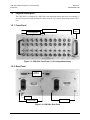
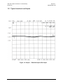
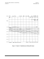
1.1.1 Compatibility .............................................................................................................. 1–2 1.2 Physical Description...................................................................................................... 1–3 1.2.1 Front Panel .................................................................................................................. 1–3 1.2.2 Rear Panel ................................................................................................................... 1–3 1.2.3 Dimensional Envelope ................................................................................................ 1–4 1.3 Summary of Specifications ........................................................................................... 1–5 1.3.1 Typical Insertion Loss Graphs .................................................................................... 1–6 CHAPTER 2. INSTALLATION ................................................................................. 2–1 2.1 Unpacking and Inspection............................................................................................ 2–1 2.2 Mounting........................................................................................................................ 2–2 CHAPTER 3. CONNECTOR PINOUTS ................................................................... 3–1 3.1 Connector Overview ..................................................................................................... 3–1 3.2 Front Panel Connectors ................................................................................................ 3–3 3.2.1
Front Panel IF Connectors – Receive IF and Transmit IF, 50Ω Type ‘N’ ............... 3–3
3.3 Rear Panel Control Connectors ................................................................................... 3–4 3.3.1 Switch Control Interface Connectors .......................................................................... 3–4 3.3.1.1 J1 CRS Control Interface Connector, DB-25F ................................................... 3–4 3.3.1.2 J2 SMS Control Interface Connector, DB-15M ................................................. 3–4 3.3.2 Power / Ground Connections ...................................................................................... 3–5 3.3.2.1 Alternating Current (AC) Power Connectors ..................................................... 3–5 3.3.2.2 Direct Current (DC) Power Connectors (optional) ............................................. 3–5 3.3.2.3 Ground Connector ............................................................................................... 3–5 CHAPTER 4. CABLES AND CONNECTIONS ........................................................ 4–1 4.1 Overview ........................................................................................................................ 4–1 4.2 CRS-280L Control Cable Connections ....................................................................... 4–2 4.2.1 SMS-7000 1:8 Modem Protection Switch Control Cable Connection ....................... 4–2 4.2.2 CRS-400 1:8 Redundancy Switch Control Cable Connection ................................... 4–3 4.2.3 CRS-300 1:N Redundancy Switch Control Cable Connection................................... 4–3 4.2.4 CRS-500 M:N Redundancy System Control Cable Connection ................................ 4–3 4.3 CRS-280L L-Band IF Cable Connections .................................................................. 4–8 4.3.1 L-Band IF Cable Characteristics ................................................................................. 4–8 4.3.2 L-Band Switch-to-Modem Cabling Requirements ..................................................... 4–8 4.3.3 L-Band Uplink/Downlink Cable Connections ............................................................ 4–9 iv