1
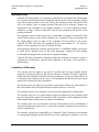
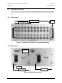
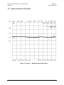
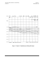
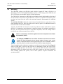
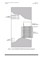
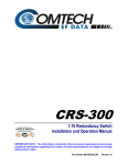
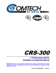
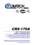
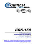
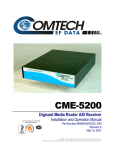
CRS-280L
L-Band IF Switch for 1:N Redundancy
Installation and Operation Manual
IMPORTANT NOTE: The information contained in this document supersedes all previously published
information regarding this product. Product specifications are subject to change without prior notice.
Part Number MN/CRS280L.IOM
Revision 1
Errata A
Comtech EF Data Documentation Update
Original Manual Part Number/Rev: MN/CRS280L.IOM Rev 1 Errata Number/ PLM Document ID: PLM CO Number: C‐0027990 Comments: The updated information will be incorporated into the next formal revision of the manual. ER-CRS280L-EA1
Change: NOTES:
1. CDM-625 and CDM-625A switch configurations are identical.
2. Throughout the manual, replace "CDM-625" with "CDM-625/A". ER-CRS280L-EA1 Rev -
This document is not subject to revision/update!
PLM CO C-0027990
Page 1 of 2
This page is intentionally blank. ER-CRS280L-EA1 Rev -
This document is not subject to revision/update!
PLM CO C-0027990
Page 2 of 2
CRS-280L
L-Band IF Switch for 1:N Redundancy
Installation and Operation Manual
Part Number MN/CRS280L.IOM
Revision 1
December 17, 2009
Copyright © 2009 Comtech EF Data. All rights reserved. Printed in the USA.
Comtech EF Data, 2114 West 7th Street, Tempe, Arizona 85281 USA, 480.333.2200, FAX: 480.333.2161
This page is intentionally blank.
Table of Contents
TABLE OF CONTENTS................................................................................................. III TABLES ......................................................................................................................... VI FIGURES .......................................................................................................................VI PREFACE ..................................................................................................................... VII About this Manual ...................................................................................................................... vii Reporting Comments or Suggestions Concerning this Manual ................................................ vii Related Documents ..................................................................................................................... vii Conventions and References ..................................................................................................... viii Cautions and Warnings ............................................................................................................ viii Metric Conversion ................................................................................................................... viii Recommended Standard Designations .................................................................................... viii Telecommunications Terminal Equipment Directive............................................................. viii Federal Communications Commission (FCC) ........................................................................ viii Electrical Safety ........................................................................................................................... ix Fuses .......................................................................................................................................... ix Environmental ............................................................................................................................ ix Installation.................................................................................................................................. ix International Symbols ................................................................................................................. x EMC (Electromagnetic Compatibility) ....................................................................................... x EN55022 - 1997 Compliance...................................................................................................... x EN55024 - 1998 Compliance...................................................................................................... x Warranty Policy ........................................................................................................................... xi Limitations of Warranty ............................................................................................................. xi Exclusive Remedies .................................................................................................................. xii Customer Support ...................................................................................................................... xiii Online Customer Support ........................................................................................................ xiii CHAPTER 1. INTRODUCTION ................................................................................ 1–1 1.1 Overview ........................................................................................................................ 1–1 iii
CRS-280L L-Band IF Switch for 1:N Redundancy
Table of Contents
Revision 1
MN/CRS280L.IOM
1.1.1 Compatibility .............................................................................................................. 1–2 1.2 Physical Description...................................................................................................... 1–3 1.2.1 Front Panel .................................................................................................................. 1–3 1.2.2 Rear Panel ................................................................................................................... 1–3 1.2.3 Dimensional Envelope ................................................................................................ 1–4 1.3 Summary of Specifications ........................................................................................... 1–5 1.3.1 Typical Insertion Loss Graphs .................................................................................... 1–6 CHAPTER 2. INSTALLATION ................................................................................. 2–1 2.1 Unpacking and Inspection............................................................................................ 2–1 2.2 Mounting........................................................................................................................ 2–2 CHAPTER 3. CONNECTOR PINOUTS ................................................................... 3–1 3.1 Connector Overview ..................................................................................................... 3–1 3.2 Front Panel Connectors ................................................................................................ 3–3 3.2.1
Front Panel IF Connectors – Receive IF and Transmit IF, 50Ω Type ‘N’ ............... 3–3
3.3 Rear Panel Control Connectors ................................................................................... 3–4 3.3.1 Switch Control Interface Connectors .......................................................................... 3–4 3.3.1.1 J1 CRS Control Interface Connector, DB-25F ................................................... 3–4 3.3.1.2 J2 SMS Control Interface Connector, DB-15M ................................................. 3–4 3.3.2 Power / Ground Connections ...................................................................................... 3–5 3.3.2.1 Alternating Current (AC) Power Connectors ..................................................... 3–5 3.3.2.2 Direct Current (DC) Power Connectors (optional) ............................................. 3–5 3.3.2.3 Ground Connector ............................................................................................... 3–5 CHAPTER 4. CABLES AND CONNECTIONS ........................................................ 4–1 4.1 Overview ........................................................................................................................ 4–1 4.2 CRS-280L Control Cable Connections ....................................................................... 4–2 4.2.1 SMS-7000 1:8 Modem Protection Switch Control Cable Connection ....................... 4–2 4.2.2 CRS-400 1:8 Redundancy Switch Control Cable Connection ................................... 4–3 4.2.3 CRS-300 1:N Redundancy Switch Control Cable Connection................................... 4–3 4.2.4 CRS-500 M:N Redundancy System Control Cable Connection ................................ 4–3 4.3 CRS-280L L-Band IF Cable Connections .................................................................. 4–8 4.3.1 L-Band IF Cable Characteristics ................................................................................. 4–8 4.3.2 L-Band Switch-to-Modem Cabling Requirements ..................................................... 4–8 4.3.3 L-Band Uplink/Downlink Cable Connections ............................................................ 4–9 iv
CRS-280L L-Band IF Switch for 1:N Redundancy
Table of Contents
Revision 1
MN/CRS280L.IOM
CHAPTER 5. REDUNDANCY SYSTEM CONFIGURATION / OPERATION ........... 5–1 5.1 Overview ........................................................................................................................ 5–1 5.2 CRS-280L Input Power Cord Connections ................................................................ 5–1 5.3 1:N Redundancy System Power-up Sequence ............................................................ 5–2 5.3.1 CRS-280L operations with the CRS-500 M:N Redundancy System ......................... 5–2 APPENDIX A. CABLE DRAWINGS ......................................................................... A-1 A.1 Introduction ................................................................................................................... A-1 A.2 Control Interface Cables .............................................................................................. A-1 A.2.1 SMS-7000 Control Cable ........................................................................................ A-2 A.2.2 CRS-400/CRS-300 Control Cable .......................................................................... A-3 A.2.3 CRS-500 Control Cable .......................................................................................... A-4 A.3 IF Interface Cable, Type ‘N’ 50Ω ................................................................................ A-5 APPENDIX B. CRS-280L POWER SUPPLY MODULE REPLACEMENT .............. B–1 B.1 Introduction ...................................................................................................................B–1 B.2 Power Supply Module Removal Procedure ................................................................B–2 B.3 Power Supply Module Installation Procedure ...........................................................B–4 v
CRS-280L L-Band IF Switch for 1:N Redundancy
Table of Contents
Revision 1
MN/CRS280L.IOM
Tables
Table 3-1. CRS-280L External Connectors (Front and Rear Panel) .......................................... 3–2 Figures
Figure 1-1. CRS-280L L-Band IF Switch for 1:N Redundancy ................................................. 1–1
Figure 1-2. 1:10 Redundancy w/CRS-280L – System-level Block Diagram ............................. 1–2
Figure 1-3. CRS-280L Front Panel (1:10 Configuration shown) ............................................... 1–3
Figure 1-4. CRS-280L Rear Panel .............................................................................................. 1–3
Figure 1-5. CRS-280L Dimensional Envelope ........................................................................... 1–4
Figure 1-6. Graph 1 – Downlink Input to Rx Output ................................................................. 1–6
Figure 1-7. Graph 2 – Downlink Input to Backup Rx Output .................................................... 1–7
Figure 1-8. Graph 3 – Backup Input to Selected Uplink Output ................................................ 1–8
Figure 1-9. Graph 4 – Tx Input to Associated Uplink Output .................................................... 1–9
Figure 2-1. Typical CRS-280L/CRS-300/CRS-350 Rack Mounting Configuration ......................... 2–3
Figure 2-2. Typical CRS-280L/CRS-500/CRS-350 Rack Mounting Configuration ......................... 2–4
Figure 3-1. CRS-280L Connectors ............................................................................................. 3–1
Figure 4-1. SMS-7000 to CRS-280L Control Cable Connection ............................................... 4–4
Figure 4-2. CRS-400 to CRS-280L Control Cable Connection ................................................. 4–5
Figure 4-3. CRS-300 to CRS-280L Control Cable Connection ................................................. 4–6
Figure 4-4. CRS-500 to CRS-280L Control Cable Connection ................................................. 4–7
Figure A-1. CRS-280L Æ SMS-7000 Data Switch Unit (DSU) Control Cable (CEFD P/N CA/5343-1)
............................................................................................................................................. A-2
Figure A-2. CRS-280L Æ CRS-400, CRS-300 Control Cable (CEFD P/N CA/WR0066) ....... A-3
Figure A-3. CRS-280L Æ CRS-500 Data Switch Unit (DSU) Control Cable (CEFD P/N CA-0000405)
............................................................................................................................................. A-4
Figure A-4. Type ‘N’ 50Ω IF Coax Cable (CEFD P/N CA/RF10453-x) ................................... A-5
Figure B-1. CRS-280L Rear Panel (shown with PL/10207-1 AC Modules) ............................. B–1
vi
PREFACE
About this Manual
This manual provides installation and operation information for the Comtech EF Data CRS-280L
L-Band IF Switch, designed for use as a companion product in Comtech 1:N Redundancy Systems.
This is a technical document intended for earth station engineers, technicians, and operators
responsible for the operation and maintenance of the CRS-280L.
Revision 1 denotes a complete rewrite of this Installation and Operation Manual (CEFD P/N
MN/CRS280L.IOM). It is intended replace the previous versions of this document in its entirety.
All content has been reorganized and updated to conform to current Comtech EF Data Technical
Publications Standards and Practices.
Reporting Comments or Suggestions Concerning this Manual
Comments and suggestions regarding the content and design of this manual will be appreciated.
To submit comments, please contact the Comtech EF Data Technical Publications Department:
[email protected].
Related Documents
•
Comtech EF Data CRS-300 1:10 Redundancy Switch Installation and Operation Manual
•
Comtech EF Data CRS-500 M:N Redundancy System Installation and Operation Manual
•
Comtech EF Data SMS-7000 1:8 Modem Protection Switch Installation and Operation Manual
(legacy product, no longer in production)
•
Comtech EF Data CRS-400 1:8 Redundancy Switch Installation and Operation Manual (legacy
product, no longer in production)
vii
CRS-280L L-Band IF Switch for 1:N Redundancy
Preface
Revision 1
MN/CRS280L.IOM
Conventions and References
Cautions and Warnings
WARNING indicates a potentially hazardous situation that, if not avoided, could
result in death or serious injury.
WARNING
CAUTION
CAUTION indicates a hazardous situation that, if not avoided, may result in minor
or moderate injury. CAUTION may also be used to indicate other unsafe practices
or risks of property damage.
IMPORTANT or NOTE indicates information critical for proper equipment function.
IMPORTANT
Metric Conversion
Metric conversion information is located on the inside back cover of this manual. This information
is provided to assist the operator in cross-referencing non-metric to metric conversions.
Recommended Standard Designations
Recommended Standard (RS) Designations have been superseded by the new designation of the
Electronic Industries Association (EIA). References to the old designations are shown only when
depicting actual text displayed on the screen of the unit (RS-232, RS-485, etc.). All other references
in the manual will be shown with the EIA designations.
Telecommunications Terminal Equipment Directive
In accordance with the Telecommunications Terminal Equipment Directive 91/263/EEC, this
equipment should not be directly connected to the Public Telecommunications Network.
Federal Communications Commission (FCC)
This equipment has been tested and found to comply with the limits for a Class A digital device,
pursuant to Part 15 of the FCC rules. These limits are designed to provide reasonable protection
against harmful interference when the equipment is operated in a commercial environment.
This equipment generates, uses, and can radiate radio frequency energy. If not installed and used
in accordance with the instruction manual, it may cause harmful interference to radio
communications. Operation of this equipment in a residential area is likely to cause harmful
interference; in which case, users are required to correct the interference at their own expense.
viii
CRS-280L L-Band IF Switch for 1:N Redundancy
Preface
Revision 1
MN/CRS280L.IOM
The user should carefully review the following information:
IMPORTANT
Electrical Safety
The CRS-280L has been shown to comply with the following safety standard:
•
EN60950: Safety of Information Technology Equipment, including electrical business
machines
The equipment is rated for operation over the range 90-264 volts AC per each power supply. Each
has a maximum power consumption of 25 Watts and draws a maximum of 0.75 Amps rms max @
90 Volts AC, and 0.35 Amps rms max @ 230 Volts AC.
Optionally, the equipment is rated for operation over the range of 36-72 volts DC per each supply.
Each has a maximum power consumption of 25 Watts and draws a maximum of 6.25 Amps.
Fuses
FOR CONTINUED OPERATOR SAFETY, ALWAYS REPLACE THE FUSES WITH
THE CORRECT TYPE AND RATING.
CAUTION
The AC-powered CRS-280L is outfitted with two power supplies, each containing two fuses –
one each for line and neutral connections. These are contained within the body of each IEC power
inlet connector, behind a small plastic flap.
• For 230 volt AC operation, use T2.5A, 20mm fuses.
• For 115 volt AC operation, use T5.0A fuses, slow blow, P/N 5ASB-IEC.
The optionally DC-powered CRS-280L is outfitted with two power supplies. Each power supply
contains one fuse installed into a fuse holder.
• For 48 volt DC operation, use T6.25A 3AG fuses.
Environmental
The CRS-280L must not be operated in an environment where the unit is exposed to extremes of
temperature outside the ambient range 0 to 50°C, precipitation, condensation, or humid
atmospheres above 95% RH, altitudes (non-pressurized) greater than 2000 meters, excessive dust
or vibration, flammable gases, corrosive or explosive atmospheres.
Operation in vehicles or other transportable installations that are equipped to provide a stable
environment is permitted. If such vehicles do not provide a stable environment, safety of the
equipment to EN60950 may not be guaranteed.
Installation
The installation and connection to the line supply must be made in compliance to local or national
wiring codes and regulations.
ix
CRS-280L L-Band IF Switch for 1:N Redundancy
Preface
Revision 1
MN/CRS280L.IOM
The CRS-280L is designed for connection to a power system that has separate ground, line and
neutral conductors. The equipment is not designed for connection to a power system that has no
direct connection to ground.
The CRS-280L is shipped with line inlet cables suitable for use in the country of operation. If it is
necessary to replace these cables, ensure the replacement has an equivalent specification.
Examples of acceptable ratings for the cable include HAR, BASEC and HOXXX-X. Examples of
acceptable connector ratings include VDE, NF-USE, UL, CSA, OVE, CEBEC, NEMKO,
DEMKO, BS1636A, BSI, SETI, IMQ, KEMA-KEUR and SEV.
International Symbols
International Symbols
Symbol
Definition
Symbol
Definition
~
Alternating Current
Protective Earth
Fuse
Chassis Ground
EMC (Electromagnetic Compatibility)
This is a Class A product. In a domestic environment, it may cause radio interference that
requires the user to take adequate protection measures.
EN55022 - 1997 Compliance
This equipment meets the radio disturbance characteristic specifications for information technology
equipment as defined in EN55022-1997.
EN55024 - 1998 Compliance
This equipment meets the EMC/immunity characteristics for the limits and methods of measurement
for information technology equipment per EN55024-1998.
IMPORTANT
To ensure that the CRS-280L continues to comply with these standards,
observe the following instructions:
•
Connections to the transmit and receive IF ports (‘N’ type female connectors) should be made
using a good quality coaxial cable; for example, RG213/U.
•
The 'D' type connector attached to the rear panel must have a back-shell that provides
continuous metallic shielding. Cable with a continuous outer shield (either foil or braid, or
both) must be used, and the shield must be bonded to the back-shell.
•
The equipment must be operated with both AC module panels assembled firmly to the rear of
the chassis at all times. If it becomes necessary to remove either AC module, the user should
ensure that the cover is correctly re-fitted before normal operation commences.
x
CRS-280L L-Band IF Switch for 1:N Redundancy
Preface
Revision 1
MN/CRS280L.IOM
Warranty Policy
Comtech EF Data products are warranted against defects in material and workmanship
for a specific period from the date of shipment, and this period varies by product. In most
cases, the warranty period is two years. During the warranty period, Comtech EF Data
will, at its option, repair or replace products that prove to be defective. Repairs are
warranted for the remainder of the original warranty or a 90 day extended warranty,
whichever is longer. Contact Comtech EF Data for the warranty period specific to the
product purchased.
For equipment under warranty, the owner is responsible for freight to Comtech EF Data
and all related customs, taxes, tariffs, insurance, etc. Comtech EF Data is responsible for
the freight charges only for return of the equipment from the factory to the owner.
Comtech EF Data will return the equipment by the same method (i.e., Air, Express,
Surface) as the equipment was sent to Comtech EF Data.
All equipment returned for warranty repair must have a valid RMA number issued prior
to return and be marked clearly on the return packaging. Comtech EF Data strongly
recommends all equipment be returned in its original packaging.
Comtech EF Data Corporation’s obligations under this warranty are limited to repair or
replacement of failed parts, and the return shipment to the buyer of the repaired or
replaced parts.
Limitations of Warranty
The warranty does not apply to any part of a product that has been installed, altered,
repaired, or misused in any way that, in the opinion of Comtech EF Data Corporation,
would affect the reliability or detracts from the performance of any part of the product, or
is damaged as the result of use in a way or with equipment that had not been previously
approved by Comtech EF Data Corporation.
The warranty does not apply to any product or parts thereof where the serial number or
the serial number of any of its parts has been altered, defaced, or removed.
The warranty does not cover damage or loss incurred in transportation of the product.
The warranty does not cover replacement or repair necessitated by loss or damage from
any cause beyond the control of Comtech EF Data Corporation, such as lightning or other
natural and weather related events or wartime environments.
The warranty does not cover any labor involved in the removal and or reinstallation of
warranted equipment or parts on site, or any labor required to diagnose the necessity for
repair or replacement.
The warranty excludes any responsibility by Comtech EF Data Corporation for incidental
or consequential damages arising from the use of the equipment or products, or for any
xi
CRS-280L L-Band IF Switch for 1:N Redundancy
Preface
Revision 1
MN/CRS280L.IOM
inability to use them either separate from or in combination with any other equipment or
products.
A fixed charge established for each product will be imposed for all equipment returned
for warranty repair where Comtech EF Data Corporation cannot identify the cause of the
reported failure.
Exclusive Remedies
Comtech EF Data Corporation’s warranty, as stated is in lieu of all other warranties,
expressed, implied, or statutory, including those of merchantability and fitness for a
particular purpose. The buyer shall pass on to any purchaser, lessee, or other user of
Comtech EF Data Corporation’s products, the aforementioned warranty, and shall
indemnify and hold harmless Comtech EF Data Corporation from any claims or liability of
such purchaser, lessee, or user based upon allegations that the buyer, its agents, or
employees have made additional warranties or representations as to product preference or
use.
The remedies provided herein are the buyer’s sole and exclusive remedies. Comtech EF
Data shall not be liable for any direct, indirect, special, incidental, or consequential
damages, whether based on contract, tort, or any other legal theory.
xii
CRS-280L L-Band IF Switch for 1:N Redundancy
Preface
Revision 1
MN/CRS280L.IOM
Customer Support
Refer to p. xi in this Preface for information regarding this product’s Warranty Policy.
Contact the Comtech EF Data Customer Support Department for:
•
Product support or training;
•
Reporting comments or suggestions concerning manuals;
•
Information on upgrading or returning a product.
A Customer Support representative may be reached at:
Comtech EF Data
Attention: Customer Support Department
2114 West 7th Street
Tempe, Arizona 85281 USA
480.333.2200 (Main Comtech EF Data number)
480.333.4357 (Customer Support Desk)
480.333.2161 FAX
To return a Comtech EF Data product (in-warranty and out-of-warranty) for repair or
replacement:
•
Contact the Comtech EF Data Customer Support Department. Be prepared to supply
the Customer Support representative with the model number, serial number, and a
description of the problem.
•
Request a Return Material Authorization (RMA) number from the Comtech EF Data
Customer Support representative.
•
Pack the product in its original shipping carton/packaging to ensure that the product is
not damaged during shipping.
•
Ship the product back to Comtech EF Data. (Shipping charges should be prepaid.)
Online Customer Support
An RMA number request can be requested electronically by contacting the Customer Support
Department through the online support page at www.comtechefdata.com/support.asp:
•
Click on the “Service” hyperlink, then read the “Return Material Authorization”
section for detailed instructions on our return procedures.
•
Click on the “RMA Request Form” hyperlink, then fill out the form completely before
sending.
•
Send e-mail to the Customer Support Department at [email protected].
xiii
CRS-280L L-Band IF Switch for 1:N Redundancy
Preface
Revision 1
MN/CRS280L.IOM
Notes:
xiv
Chapter 1. INTRODUCTION
1.1
Overview
Figure 1-1. CRS-280L L-Band IF Switch for 1:N Redundancy
The CRS-280L L-Band IF Switch (Figure 1-1) is designed to support redundancy systems
featuring one Redundant (backup) Modem and up to 10 Traffic Modems (prime channels).
Operation of the CRS-280L is controlled by the switching system to which it is connected. The
CRS-280L is designed for use with the following Comtech EF Data products:
Modem
Remarks
Max 1:N Redundancy
CDM-570L
Used with CRS-300 or CRS-500
1:10
Used with CRS-300 or CRS-500 w/CRS-350 (ESC only)
1:10
SDM-300L3**
Used with SMS-7000**
1:8
SDM-2020D**
(L-Band)
Used with CRS-400 (HSSI)**
1:10
CDM-600L
CLM-9600L
CDM-625
SLM-5650A
** Indicates a Comtech EF Data legacy product that is no longer in production
The CRS-280L replaces the following Comtech EF Data active or legacy products:
•
IFU for SMS-7000 L-Band applications.
•
CRS-280 IF switch for L-Band applications (CRS-300/CRS-500)
The CRS-280L features redundant power supplies with status LEDs on the front panel. It may be
configured for 4 to 10 channel applications (SMS-7000 supports 8 channels max). Each channel
1–1
CRS-280L L-Band IF Switch for 1:N Redundancy
Introduction
Revision 1
MN/CRS280L.IOM
has a transmit section with TX input / uplink output and a receive section with Rx output /
downlink input.
Figure 1-2 depicts the system level block diagram for a CRS-280L-equipped 1:10 redundancy
system.
Test
Out
Uplink Outputs
Tx1
Tx2
Tx3
Tx4
Tx5
Tx6
Tx7
Tx8
Tx9
Tx10
Redundant
Power
Control
Interface
& Drivers
Backup
Modulator
A
B
CRS
SMS
Prime Modulators
Test
In
Downlink Inputs
Rx1
Splitter
Rx2
Splitter
Backup
Demodulator
Rx3
Splitter
Rx4
Splitter
Rx5
Rx6
Splitter
Splitter
Rx7
Splitter
Rx8
Splitter
Rx9
Splitter
Rx10
Splitter
Prime Demodulators
Figure 1-2. 1:10 Redundancy w/CRS-280L – System-level Block Diagram
1.1.1 Compatibility
CAUTION
1. The Comtech EF Data CRS-280L L-Band IF Switch is designed specifically as
an accessory product for Comtech EF Data equipment. It is not designed to
operate with any other manufacturer's equipment.
2. The CRS-280L is not designed to convey DC power to external equipment such
as LNBs or BUCs. Do not apply DC power to the L-Band input and output
(Type ‘N’) ports of the switch. In addition, the CRS-280L is not designed to
pass to 10 MHz reference or FSK signaling.
1–2
CRS-280L L-Band IF Switch for 1:N Redundancy
Introduction
1.2
Revision 1
MN/CRS280L.IOM
Physical Description
The CRS-280L is constructed as a 4RU-high, rack-mounting chassis that can be freestanding, if
desired. It is provided with rack handles at the front for easy removal from and placement into a
rack.
1.2.1 Front Panel
1:10 Configuration
Status
LEDs
1:4 Configuration
Figure 1-3. CRS-280L Front Panel (1:10 Configuration shown)
1.2.2 Rear Panel
Control
Interfaces
Ground
Power Supply
Power Supply
Figure 1-4. CRS-280L Rear Panel
1–3
CRS-280L L-Band IF Switch for 1:N Redundancy
Introduction
Revision 1
MN/CRS280L.IOM
1.2.3 Dimensional Envelope
17.00
(43.18)
13.92
(35.36)
13.18
(33.48)
6.96
(17.68)
19.00
(48.26)
Figure 1-5. CRS-280L Dimensional Envelope
1–4
CRS-280L L-Band IF Switch for 1:N Redundancy
Introduction
1.3
Revision 1
MN/CRS280L.IOM
Summary of Specifications
Equipment Type
L-Band IF Switch for 1:N Redundancy
Comtech EF Data Modems Supported
•
•
•
•
•
•
•
Tx/Rx Operating Frequency
950 - 1950 MHz (L-Band)
IF Impedance
50Ω
TX Return Loss
15 dB at 50 Ω
TX to TX Channel Isolation
>70 dB
RX to RX Channel Isolation
>70 dB
TX to RX Channel Isolation
>90 dB
SDM-2020D (L-Band) (when used with CRS-400) (legacy products)
SDM-300L3 (when used with SMS-7000) (legacy products)
CDM-570L (when used with CRS-300 or CRS-500)
CDM-600L (when used with CRS-300)
CDM-9600L (when used with CRS-300)
CDM-625 (when used with CRS-300 or CRS-500)
SLM-5650A (when used with CRS-300 or CRS-500)
Tx IF Loss / Flatness
TX (in) to associated Uplink (out)
< 0.8 dB / 0.5 dB over operating frequency
BU (in) to any Uplink (out)
< 2.5 dB / 1.0 dB over operating frequency
Rx IF Loss / Flatness
DL (in) to associated RX (out)
< 4.0 dB / 0.5 dB over operating frequency
Any DL (in) to BU RX (out)
< 5.5 dB / 1.0 dB over operating frequency
Max. # of Downlinks
10
Tx/Rx IF Connectors
50Ω Type ‘N’ female
Control Interface
• 25-pin sub-D female, compatible with CRS-300 controller
• 15-pin sub-D female, compatible with SMS-7000
Input Power
Redundant 25 W, AC, Universal Input Switch Mode Power Supplies
Input voltage
Input frequency
Input current
Power Loss Failsafe
90 - 264 VAC
47 - 440 Hz
0.75 A rms max. @ 90 VAC
0.35 A rms @ 230 VAC
All uplinks/downlinks revert to associated L-Band inputs/outputs
Environmental
Operating Temperature
Storage Temperature
Humidity
32° to +122° F (0° to +50° C)
-58° to +212° F (-50° to +100° C)
95% at +122° F (+50° C), Non-condensing
Dimensions
(Excluding connectors) 4RU (7 inches, 177.8 mm) high X 19 inches (482.5 mm)
wide X14 inches (356 mm) deep
Weight
< 25 lbs (<11.35 kg)
EMC and Safety
• ‘CE’ as follows:
o EN 55022-1997 Class A (Emissions)
o EN-55024-1998 (EMC/Immunity)
o EN 50082-1 (Immunity)
o EN 60950 (Safety)
• FCC Part 15 Class A
1–5
CRS-280L L-Band IF Switch for 1:N Redundancy
Introduction
Revision 1
MN/CRS280L.IOM
1.3.1 Typical Insertion Loss Graphs
Figure 1-6. Graph 1 – Downlink Input to Rx Output
1–6
CRS-280L L-Band IF Switch for 1:N Redundancy
Introduction
Revision 1
MN/CRS280L.IOM
Figure 1-7. Graph 2 – Downlink Input to Backup Rx Output
1–7
CRS-280L L-Band IF Switch for 1:N Redundancy
Introduction
Revision 1
MN/CRS280L.IOM
Figure 1-8. Graph 3 – Backup Input to Selected Uplink Output
1–8
CRS-280L L-Band IF Switch for 1:N Redundancy
Introduction
Revision 1
MN/CRS280L.IOM
Figure 1-9. Graph 4 – Tx Input to Associated Uplink Output
1–9
CRS-280L L-Band IF Switch for 1:N Redundancy
Introduction
Revision 1
MN/CRS280L.IOM
Notes:
1–10
Chapter 2. INSTALLATION
2.1
Unpacking and Inspection
The CRS-280L L-Band IF Switch for 1:N Redundancy and its Installation and Operation Manual
are packaged and shipped in a pre-formed, reusable cardboard carton containing foam spacing for
maximum shipping protection.
CAUTION
Do not use any cutting tool that will extend more than 1” into the container
and cause damage to the unit.
Be sure to keep all shipping materials for the carrier's inspection.
IMPORTANT
Unpack and inspect the CRS-280L as follows:
Step
Procedure
1
Inspect shipping containers for damage.
2
If shipping containers are damaged, keep them until the contents of the shipment
have been carefully inspected and checked for normal operation.
3
Remove the packing list from the outside of the shipping carton.
4
Open the carton and remove the contents.
5
Check the contents against the packing list to verify completeness of the shipment.
6
If damage is evident, contact the carrier and Comtech EF Data immediately and
submit a damage report.
7
If the unit needs to be returned to Comtech EF Data, use the original shipping
container.
2–1
CRS-280L L-Band IF Switch for 1:N Redundancy
Installation
2.2
Revision 1
MN/CRS280L.IOM
Mounting
The CRS-280L replaces the CRS-280 (used with the Comtech EF Data’s CRS-300 1:10
Redundancy Switch, CRS-500 M:N Redundancy System, or CEFD legacy product CRS-400) and
IFU (CEFD legacy product SMS-7000) for L-Band applications.
The CRS-280L is constructed as a 4RU-high, rack-mounting chassis. Rack handles at the front of
the unit facilitate removal from and placement into a rack. It is compatible with mounting at the
top, back, or front of the rack (refer to the associated controller documentation for additional
details).
To install the CRS-280L: Mount the switch with user-furnished hardware, using the unit’s front
panel mounting holes only. Since the switch itself is relatively passive, no additional clearance is
needed between it and the nearest Modem.
Typically, the CRS-280L is mounted in a rack along with the modems with which it operates;
therefore, it is important to ensure that there is adequate clearance for ventilation, particularly at
the sides. In rack systems where there is high heat dissipation, forced air cooling must be
provided by top or bottom mounted fans or blowers.
Under no circumstance should the highest internal rack temperature be allowed
to exceed 50°C (122°F).
CAUTION
IMPORTANT
The CRS-280L CANNOT have rack slides mounted to the side of the chassis.
Comtech EF Data recommends that an alternate method of support, such as rack
shelves, is employed within the rack if front-mounting the unit is not feasible. If there is
any doubt, please consult the Comtech EF Data Customer Support department.
Typical installation and configuration examples are provided on the pages that follow: Figure 2-1
shows the CRS-280L as used with the CRS-300 1:10 Redundancy Switch and CRS-350 ESC
Switch, while Figure 2-2 shows the CRS-280L as used with the CRS-350 and the CRS-500 M:N
Redundancy System. For further details on the CRS-280L’s tandem use with other Comtech EF
Data switching products and systems, refer to those products’ respective installation and
operation manuals.
2–2
CRS-280L L-Band IF Switch for 1:N Redundancy
Installation
Revision 1
MN/CRS280L.IOM
CRS-280L
Rx/Tx IF Switch
CRS-300 1:10
Redundancy Switch
Redundant Modem
Up to 10
Traffic Modems
CRS-350
ESC Switch
Figure 2-1. Typical CRS-280L/CRS-300/CRS-350 Rack Mounting Configuration
2–3
CRS-280L L-Band IF Switch for 1:N Redundancy
Installation
Revision 1
MN/CRS280L.IOM
CRS-280L
Rx/Tx IF Switch
1 or 2 Redundant
Modems
Up to 4 CRS-500
Rx/Tx ISUs
(CRS-282xx)
CRS-500 CSU
Up to 9 or 10
Traffic Modems
CRS-350
ESC Switch
CRS-500 DSU
Figure 2-2. Typical CRS-280L/CRS-500/CRS-350 Rack Mounting Configuration
(CRS-500 DSU Bottom Mount configuration, 4X ISUs shown)
2–4
Chapter 3. CONNECTOR PINOUTS
3.1
Connector Overview
Front Panel View
R
e
a
r
P
a
n
e
l
Rear Panel View (Standard AC Unit shown)
Figure 3-1. CRS-280L Connectors
The front and rear panels of the CRS-280L L-Band IF Switch are shown in Figure 3-1.
The front panel connectors provide all necessary to connect all equipment internal and external to
the 1:N redundancy setup. The rear panel connectors of the CRs-280L provide the control
connectors between the CRS-280L and its companion redundancy switch (e.g., CRS-300,
CRS-500, etc.).
On the next page, Table 3-1 summarizes these connectors, grouped according to location (front,
rear, or data interface) and service function.
3–1
CRS-280L L-Band IF Switch for 1:N Redundancy
Connector Pinouts
Revision 1
MN/CRS280L.IOM
Table 3-1. CRS-280L External Connectors (Front and Rear Panel)
Connector Group
(Chapter 3 Sect. Ref.)
Front Panel
(Sect. 3.2)
Name
IF
(Sect. 3.2.1)
(Transmit IF)
(Receive IF)
Rear Panel
(Sect. 3.3)
Connector Type
Control Interface
(Sect. 3.3.1)
Power / Ground
(Sect 3.3.2)
22X Type ‘N’ 50Ω female
22X Type ‘N’ 50Ω female
Function
L-Band
Input
L-Band
Output
Tx Backup
Tx Traffic 1-10
Rx Backup
Rx Traffic 1-10
Test Out
Tx In
Up Link Out
Tx In
Test In
Rx Out
Down Link In
Rx out
J1
CRS CONTROL
INTERFACE
25-pin Type ‘D’ female
Control interface for CRS-400**, CRS-300,
CRS-500 Redundancy Switching products
J2 SMS CONTROL
INTERFACE
15-pin Type ‘D’ male
Control interface for SMS-7000** Redudancy
Switching Product
AC Input
2X IEC
p/o Primary and Backup AC Power Supply
Modules (CEFD P/N PL/10207-1)
DC Input
2X 3-screw Terminal Block
p/o Optional Primary and Backup DC Power
Supply Modules (CEFD P/N PL-0000355)
Ground
#10-32 stud
Common Chassis Ground
** Indicates a Comtech EF Data legacy product that is no longer in production.
IMPORTANT
The European EMC Directive (EN55022, EN50082-1) requires using properly shielded
cables for DATA I/O. These cables must be double-shielded from end-to-end,
ensuring a continuous ground shield.
3–2
CRS-280L L-Band IF Switch for 1:N Redundancy
Connector Pinouts
3.2
Revision 1
MN/CRS280L.IOM
Front Panel Connectors
Unless otherwise noted, the connectors featured on the front panel of the CRS-280L are intended
for connection to all IF equipment internal and external to the 1:N redundancy setup.
3.2.1
Front Panel IF Connectors – Receive IF and Transmit IF, 50Ω Type ‘N’
Each Transmit IF and Receive IF port connector is a 50Ω Type ‘N’ female
connector. Observe the following:
Connector
Pair
IF Side
Tx Backup (Tx Redundant)
Transmit IF
Tx 1 through Tx 10 (Tx Traffic)
Rx Backup (Rx Redundant)
Receive IF
Rx 1 through Rx 10 (Rx Traffic)
Connector Name
Test Out
Tx In
Up Link Out
Tx In
Test In
Rx Out
Down Link In
Rx out
See Chapter 4. CABLES AND CONNECTIONS for complete details on IF cabling between
the CRS-280L and its companion redundant switches, redundant and traffic modems, and uplink
and downlink equipment.
3–3
CRS-280L L-Band IF Switch for 1:N Redundancy
Connector Pinouts
3.3
Revision 1
MN/CRS280L.IOM
Rear Panel Control Connectors
Unless otherwise noted, the connectors featured on the rear panel of the CRS-280L are intended
for connection to the companion redundancy switch control interface.
3.3.1
Switch Control Interface Connectors
3.3.1.1
J1 CRS Control Interface Connector, DB-25F
The 25-pin ‘D’ Type female (DB-25F) J1 CRS Control Interface
connector is used to connect the CRS-280L to the IF Switch Control
port, located on the CRS-230 Controller card installed in the CRS-400
1:8 Redundancy Switch or CRS-300 1:10 Redundancy Switch, or to the
P1 IF Switch Control port located on the control interface side of the CRS-500 M:N Redundancy
System’s Data Switch Unit (DSU).
NOTE
The Comtech EF Data CRS-400 1:8 Redundancy Switch is a legacy product that is
no longer in production.
The J1 CRS Control Interface connector communicates with the logic interface of the companion
redundancy switch to drive the currently selected terrestrial modem, and to decide whether the
system is in bridged or backup mode. The CRS-280L performs the same bridging and backing up
functions of the Tx and Rx IF signals to match what the companion redundant switch does to the
terrestrial data signals.
3.3.1.2
J2 SMS Control Interface Connector, DB-15M
The 15-pin ‘D’ Type male (DB-15M) J2 SMS Control Interface
connector is used to connect the CRS-280L to the J12 IF Control
Interface port of SMS-7000 1:8 Modem Protection Switch’s Data
Switch Unit (DSU).
NOTE
The Comtech EF Data SMS-7000 1:8 Modem Protection Switch is a legacy
product that is no longer in production.
3–4
CRS-280L L-Band IF Switch for 1:N Redundancy
Connector Pinouts
3.3.2
Revision 1
MN/CRS280L.IOM
Power / Ground Connections
For continued operator safety, always replace fuses with the correct type and
rating.
IMPORTANT
3.3.2.1
Alternating Current (AC) Power Connectors
Two AC power supplies – one primary, one backup – are provided. For each, a
standard, detachable, non-locking 3-prong power cord (IEC plug) supplies the
Alternating Current (AC) power to the CRS-280L. Observe the following:
Standard AC Power Specifications
3.3.2.2
Input Power
25W typical
Input Voltage
100 - 240 volts AC, +6%/-10% - autosensing
(total absolute max. range is 90-264 volts AC)
Connector Type
IEC
Fuse Protection
1.0A Slow-blow (115 volt AC operation)
2.0A Slow-blow (230 volt AC operation)
Line and neutral fusing
20 mm type fuses
Direct Current (DC) Power Connectors (optional)
Two DC power supplies – one primary, one backup – are
optionally available. For each, a standard, 3-screw terminal block
with fuse holder supplies the Direct Current (DC) power to the
CRS-280L. Observe the following:
Optional DC Power Specifications
3.3.2.3
Input Power
25W maximum
Input Voltage
36 to 72 VDC; 6.25 amps
Connector Type
Terminal Block
Fuse Protection
6.25A Slow-blow
Ground Connector
A #10-32 stud, located to the lower left hand side of the CRS-280L rear panel, is
provided for connecting a common chassis ground among equipment.
Note: The AC power connector provides the safety ground.
3–5
CRS-280L L-Band IF Switch for 1:N Redundancy
Connector Pinouts
Revision 1
MN/CRS280L.IOM
Notes:
3–6
Chapter 4. CABLES AND
CONNECTIONS
4.1
Overview
When assembling a Comtech EF Data 1:N Redundancy System, in addition to purchasing the
desired modem group (one Redundant modem, up to 10 Traffic modems) and the appropriate
companion switch (i.e., CRS-300, CRS-500 etc.), the user is also required to purchase all cables and
components required for interconnection of the redundant configuration to various interfaces (i.e.,
control, IF, and data).
Once the CRS-280L switch, its companion redundancy switch, and all modems have been
mounted as outlined in Chapter 2. INSTALLATION, the user must properly attach all required
cabling, then configure the system for correct operation.
For the purpose of clarity, this chapter deals only with the connections needed for the CRS-280L’s
application within a configured 1:N Redundancy System. Refer to the applicable companion switch
Installation and Operation Manual for pertinent data interface cabling and other cable connection
information.
The sections that follow in this chapter provide specific interface examples that identify the
individual redundancy cable(s) required to interconnect the two interfaces. For line drawings of the
cables specified in this chapter, see Appendix A. CABLE DRAWINGS.
1. Leave the switch and all modems powered off until all connections are
ready.
IMPORTANT
2. It is essential to ensure that both the Tx and Rx IF connections are made
correctly. For example, the Transmit IF from the Redundant Modem’s “Tx”
port must connect to the Tx IF Backup “Tx In” port on the CRS-280L, the
Traffic Modem #1’s “Tx” connector must connect to the Tx 1 “Tx In” port,
etc., and the same for all Rx IF connections. Failure to observe this
requirement will result in the system malfunctioning.
4–1
CRS-280L L-Band IF Switch for 1:N Redundancy
Cables and Connections
4.2
Revision 1
MN/CRS280L.IOM
CRS-280L Control Cable Connections
Each CRS-280L is supplied with a control cable for connection to the associated 1:N Redundancy
Switch control unit. The control cable must be specified at time of order:
1: N Redundancy Switch
CEFD Part No.
Description
SMS-7000**
CA/5343-1
Control Cable, DB-15F Æ DB-15M, 8’
CA/WR0066
Control Cable, DB-25M Æ DB-25F, 6’
CA-0000405
Multi-drop Control Cable, DB-25M Æ(4X) DB-9F, 15’)
CRS-400**
CRS-300
CRS-500
** Indicates a Comtech EF Data legacy product that is no longer in production
IMPORTANT
1. When connecting the Control cable between the CRS-280L and the
redundancy switch, ensure that screw locks on the ‘D’ type connectors are
securely fastened. This will prevent the accidental unmating of the cable,
particularly when a standby unit is being removed or replaced.
2. Only one control interface must be used. Do not make connections to
both control interfaces on the CRS-280L. The CRS-280L automatically
detects the control interface in use and cannot function with both control
cables connected.
Connect the supplied cable between the Redundancy Switch (controller) and the CRS-280L (refer
to the pertinent Redundancy Switch Installation and Operation Manual for additional information):
4.2.1
For CRS-280L Æ
Refer to:
SMS-7000 1:8 Modem Protection Switch**
Sect. 4.2.1
CRS-400 1:8 HSSI Redundancy Switch**
Sect. 4.2.2
CRS-300 1:N Redundancy Switch
Sect. 4.2.3
CRS-500 M:N Redunancy System
Sect. 4.2.4
SMS-7000 1:8 Modem Protection Switch Control Cable Connection
NOTE
The Comtech EF Data SMS-7000 1:8 Modem Protection Switch is a legacy
product that is no longer in production.
As shown in Figure 4-1:
Step
Instructions
1
Connect the DB-15F connector on the CA/5343-1 Control Cable to the DB-15M J2 SMS
Control Interface port on the rear panel of the CRS-280L.
2
Connect the DB-15M connector on the CA/5343-1 Control Cable to the DB-15F J12 IF
Control Interface port on the Control/Modem side of the SMS-7000 Data Switch Unit
(DSU).
Note: The CRS-280L serves to replace, in its entirety, the SMS-7000 IF Switch Unit (IFU).
3
Secure the cable by tightening the screw locks on both ends of the control cable.
4–2
CRS-280L L-Band IF Switch for 1:N Redundancy
Cables and Connections
4.2.2
Revision 1
MN/CRS280L.IOM
CRS-400 1:8 Redundancy Switch Control Cable Connection
NOTE
The Comtech EF Data CRS-400 1:8 Redundancy Switch is a legacy product
that is no longer in production.
As shown in Figure 4-2 :
Step
4.2.3
Instructions
1
Connect the DB-25M connector of the CA/WR0066 control cable to the DB-25F
J1 CRS Control Interface port on the rear panel of the CRS-280L.
2
Connect the other end of the control cable to the DB-25M IF Switch Control port
on the CRS-230 Controller card, installed in the rear panel of the CRS-400 1:8
Redundancy Switch.
3
Secure the cable by tightening the screw locks on both ends of the control cable.
CRS-300 1:N Redundancy Switch Control Cable Connection
As shown in Figure 4-3:
Step
4.2.4
Instructions
1
Connect the DB-25M connector of the CA/WR0066 control cable to the DB-25F
J1 CRS Control Interface port on the rear panel of the CRS-280L.
2
Connect the other end of the control cable to the DB-25M IF Switch Control port
on the CRS-230 Controller card, installed in the rear panel of the CRS-300 1:N
Redundancy Switch.
3
Secure the cable by tightening the screw locks on both ends of the control cable.
CRS-500 M:N Redundancy System Control Cable Connection
As shown in Figure 4-4:
Step
Instructions
1
Connect the DB-25M connector of the CA-0000405 Multi-drop Control Cable to the
DB-25F J1 CRS Control Interface port on the rear panel of the CRS-280L.
2
Connect the final DB-9F connector on the CA-0000405 Multi-drop Control Cable
to the DB-9M P1 IF Switch Control port on the control interface side of the
CRS-500 M:N Redundancy System’s Data Switch Unit (DSU). Be sure to tie off or
otherwise secure any unused DB-9F connectors on the CA-0000405 Multi-drop
Control Cable.
Note: The CRS-500 DSU is, in turn, connected to the CRS-500 Control Switch
Unit (CSU) via the CA-0000234 Control Cable – see the CRS-500 M:N
Redundancy System Installation and Operation Manual for complete details.
3
Secure the cable by tightening the screw locks on both ends of the control cable.
4–3
CRS-280L L-Band IF Switch for 1:N Redundancy
Cables and Connections
Revision 1
MN/CRS280L.IOM
Control Cable CA/5343-1
(DB-15F Æ DB-15M, 8’)
Figure 4-1. SMS-7000 to CRS-280L Control Cable Connection
NOTE
The Comtech EF Data SMS-7000 1:8 Modem Protection Switch is a legacy product
that is no longer in production.
4–4
CRS-280L L-Band IF Switch for 1:N Redundancy
Cables and Connections
Revision 1
MN/CRS280L.IOM
CA/WR0066 Control Cable
(DB-25F to DB-25M, 6’)
Figure 4-2. CRS-400 to CRS-280L Control Cable Connection
NOTE
The Comtech EF Data CRS-400 1:8 Redundancy Switch is a legacy product that is
no longer in production.
4–5
CRS-280L L-Band IF Switch for 1:N Redundancy
Cables and Connections
Revision 1
MN/CRS280L.IOM
CA/WR0066 Control Cable
(DB-25F to DB-25M, 6’)
Figure 4-3. CRS-300 to CRS-280L Control Cable Connection
4–6
CRS-280L L-Band IF Switch for 1:N Redundancy
Cables and Connections
Revision 1
MN/CRS280L.IOM
CA-0000234 Control Cable
(DB-25F to DB-25M, 8’) – Shown for reference only.
CA-0000405 Multi-drop Control Cable
(Use only DB-9F, DB-25M end connectors, 15’)
Figure 4-4. CRS-500 to CRS-280L Control Cable Connection
4–7
CRS-280L L-Band IF Switch for 1:N Redundancy
Cables and Connections
4.3
Revision 1
MN/CRS280L.IOM
CRS-280L L-Band IF Cable Connections
Cables for connecting the CRS-280L L-Band IF Switch to the L-Band modems within the
redundancy system are available for purchase from Comtech EF Data and can be ordered at the
same time the order is placed for the CRS-280L:
4.3.1
CEFD Part No.
Description
CA/RF10453-2
Cable Assembly, L-Band 50Ω, Type ‘N’ male to Type ‘N’ male connectors, 2’
CA/RF10453-4
Cable Assembly, L-Band 50Ω, Type ‘N’ male to Type ‘N’ male connectors, 4’
CA/RF10453-6
Cable Assembly, L-Band 50Ω, Type ‘N’ male to Type ‘N’ male connectors, 6’
CA/RF10453-8
Cable Assembly, L-Band 50Ω, Type ‘N’ male to Type ‘N’ male connectors, 8’
L-Band IF Cable Characteristics
If L-Band cables are not purchased from Comtech EF Data, use of a suitable
equivalent is recommended.
IMPORTANT
4.3.2
Cable Type
Loss at 1GHz
Loss at 2GHz
Semflex BPE200 (or equivalent)
0.11 dB/ft
0.15 dB/ft
L-Band Switch-to-Modem Cabling Requirements
The number of cables required depends on the switch system configuration. Per
the example shown at right, each modem connected to the CRS-280L front panel
requires two L-Band cables:
•
One cable for the Rx L-Band connection
•
One cable for the Tx L-Band connection
Each cable must be connected and secured using the Type ‘N’ threaded female
connectors on the front panel of the CRS-280L and rear panel of the L-Band
modems.
4–8
CRS-280L L-Band IF Switch for 1:N Redundancy
Cables and Connections
Revision 1
MN/CRS280L.IOM
Cable connections are defined as follows:
L-Band Modem Connection
Redundant Modem
Prime Modem #1
Prime Modem #2
Prime Modem #3
Prime Modem #4
Prime Modem #5
Prime Modem #6
Prime Modem #7
Prime Modem #8
Prime Modem #9
Prime Modem #10
CRS-280L Connection
TX Output ↔
TX Backup (TX In)
RX Input ↔
RX Backup (RX Out)
TX Output ↔
TX 1 (TX In)
RX Input ↔
RX 1 (RX Out)
TX Output ↔
TX 2 (TX In)
RX Input ↔
RX 2 (RX Out)
TX Output ↔
TX 3 (TX In)
RX Input ↔
RX 3 (RX Out)
TX Output ↔
TX 4 (TX In)
RX Input ↔
RX 4 (RX Out)
TX Output ↔
TX 5 (TX In)
RX Input ↔
RX 5 (RX Out)
TX Output ↔
TX 6 (TX In)
RX Input ↔
RX 6 (RX Out)
TX Output ↔
TX 7 (TX In)
RX Input ↔
RX 7 (RX Out)
TX Output ↔
TX 8 (TX In)
RX Input ↔
RX 8 (RX Out)
TX Output ↔
TX 9 (TX In)
RX Input ↔
RX 9 (RX Out)
TX Output ↔
TX 10 (TX In)
RX Input ↔
RX 10 (RX Out)
Comments
4.3.3 L-Band Uplink/Downlink Cable Connections
CAUTION
The CRS-280L is not designed to convey DCpower to external equipment such as
LNBs or BUCs. Do not apply DC power to the L-Band input and output (Type ‘N’)
ports of the switch.
CEFD recommends that connections to uplink and downlink equipment be made after all other
system cabling and configuration is complete. Cabling to and from the CRS-280L uplink and
downlink ports is dependant on the system configuration and the uplink/downlink equipment
used. For additional information, refer to the uplink/downlink equipment documentation.
4–9
CRS-280L L-Band IF Switch for 1:N Redundancy
Cables and Connections
Revision 1
MN/CRS280L.IOM
Notes:
4–10
Chapter 5. REDUNDANCY SYSTEM
CONFIGURATION / OPERATION
5.1
Overview
In order to avoid damage to the modems, the companion redundant switch, and
the CRS-280L L-Band IF Switch, and it is important for the user to follow this
sequence of configuration:
IMPORTANT
5.2
•
First, connect cables between the (powered OFF) modems, companion
redundancy switch, and CRS-280L as outlined previously in Chapter 4.
CABLES AND CONNECTIONS.
•
Second, configure the modems for 1:N redundant operation, as outlined in
the respective modem and companion switch Installation and Operation
Manuals.
•
Third, once the modems have been properly configured for 1:N redundant
operations, the user should follow the instructions in the next two chapter
sections in the sequence they are presented.
CRS-280L Input Power Cord Connections
IMPORTANT
Do not turn the CRS-280L power supply switches to the on position until all
system connections are in place.
Connect the AC power cords as follows:
Step
Instructions
1
Ensure that both power supply switches are in the off position before connecting
the power supply power cords.
2
Each CRS-280L is supplied with two power cords – one for each power supply
power input. Connect the female end of each supplied power cords to its mating
socket.
3
Plug both power cords into the AC power source.
5–1
CRS-280L L-Band IF Switch for 1:N Redundancy
Redundancy System Configuration / Operation
5.3
Revision 1
MN/CRS280L.IOM
1:N Redundancy System Power-up Sequence
After the 1:N redundant system cabling is complete, and the companion switch and modems have
been initially configured, the complete sysyem may be powered up. The typical equipment powerup sequence is as follows:
Step
Instructions
1
Turn on the redundant and traffic L-Band modems.
2
Power up the CRS-280L L-Band IF Switch switch by turning both power supply
switches, located on the CRS-280L rear panel, to the on position.
Once the power supplies are turned on, both power status LEDs (A and B) on the
front panel should illuminate green.
3
IMPORTANT
Power up the companion switch as applicable (e.g., turn on the system controller /
data switch for the CRS-300, CRS-400, or SMS-7000; turn on the CRS-500 Control
Switch Unit (CSU), etc.)
The CRS-280L is designed to operate with only one power supply energized.
However, it is recommended to continually operate the system with both
supplies energized for redundancy.
5.3.1 CRS-280L operations with the CRS-500 M:N Redundancy System
While the CRS-500 M:N Redundancy System supports 2:N redundancy and IP Sub-MUX
operation, the CRS-280L L-Band IF Switch is limited to 1:10 (maximum) redundancy – 2:N
redundancy and IP Sub-MUX operation are not supported by the CRS-280L.
5–2
Appendix A. CABLE DRAWINGS
A.1
Introduction
This appendix contains drawings of cables used with the CRS-280L L-Band IF Switch for 1:N Redundancy. These cables are broken into two
categories – Control Interface Cables and IF Interface Cables:
•
The Control Interface Cables are used to connect the CRS-280L rear panel J1 CRS Control Interface or J2 SMS Control Interface
connector to its companion redundancy switch IF Switch Control Interface connector.
•
The IF Interface Cables may be selected and used to connect the CRS-280L, via the front panel Tx/Rx Type ‘N’ threaded female
connectors, to the Redundant Modem and up to 10 traffic modems that are part of the 1:N redundancy setup, as well as to any
external uplink / downlink RF equipment.
Each section provides illustrations of the cables’ technical specifications; additionally, the table in each section cross-reference to the
illustrations found in Chapter 4. CABLES AND CONNECTIONS.
A.2
Control Interface Cables
App. A
FIG
REF Ch. 4
FIG
CEFD CABLE P/N
DESCRIPTION
USED FOR
A-1
4-1
CA/5343-1
Control Cable, DB-15F Æ DB-15M, 8’
CRS-280L Æ SMS-7000 Data Switch Unit (DSU)
A-2
4-2, 4-3
CA/WR0066
Control/Data Cable, DB-25F Æ DB-25M, 6’
CRS-280L Æ CRS-400/CRS-300
A-3
4-4
CA-0000405
Multi-drop Control Cable, DB-25M Æ (5X) DB-9F, 15’
CRS-280L Æ CRS-500 Data Switch Unit (DSU)
NOTE
The Comtech EF Data SMS-7000 1:8 Modem Protection Switch and CRS-400 1:8 Redundancy Switch are legacy
products that are no longer in production.
A-1
CRS-280L L-Band IF Switch for 1:N Redundancy
Cable Drawings
A.2.1
Revision 1
MN/CRS280L.IOM
SMS-7000 Control Cable
The Comtech EF Data SMS-7000 1:8 Modem Protection Switch is a legacy product that is no longer in production.
NOTE
Figure A-1. CRS-280L Æ SMS-7000 Data Switch Unit (DSU) Control Cable (CEFD P/N CA/5343-1)
A-2
CRS-280L L-Band IF Switch for 1:N Redundancy
Cable Drawings
A.2.2
Revision 1
MN/CRS280L.IOM
CRS-400/CRS-300 Control Cable
The Comtech EF Data CRS-400 1:8 Redundancy Switch is a legacy product that is no longer in production.
NOTE
Figure A-2. CRS-280L Æ CRS-400, CRS-300 Control Cable (CEFD P/N CA/WR0066)
A-3
CRS-280L L-Band IF Switch for 1:N Redundancy
Cable Drawings
A.2.3
Revision 1
MN/CRS280L.IOM
CRS-500 Control Cable
Figure A-3. CRS-280L Æ CRS-500 Data Switch Unit (DSU) Control Cable (CEFD P/N CA-0000405)
A-4
CRS-280L L-Band IF Switch for 1:N Redundancy
Cable Drawings
A.3
Revision 1
MN/CRS280L.IOM
IF Interface Cable, Type ‘N’ 50Ω
CEFD P/N
DIM ‘A’
CA/RF10453-2
24.00 ± .80
CA/RF10453-4
48.00 ± 1.50
CA/RF10453-6
72.00 ± 3.00
CA/RF10453-8
96.00 ± 3.00
Figure A-4. Type ‘N’ 50Ω IF Coax Cable (CEFD P/N CA/RF10453-x)
A-5
CRS-280L L-Band IF Switch for 1:N Redundancy
Cable Drawings
Revision 1
MN/CRS280L.IOM
Notes:
A-6
Appendix B. CRS-280L POWER SUPPLY
MODULE REPLACEMENT
B.1
Introduction
The CRS-280L L-Band IF Switch for 1:N
Redundancy features dual power supply modules:
the standard AC module (CEFD P/N Pl/10207-1),
or the optional DC module (CEFD P/N
PL-0000355). These modules are the only field
replaceable components in the CRS-280L.
This appendix illustrates the procedure required to
remove and install a CRS-280L power supply
module (Figure B-1) into any CRS-280L L-Band
IF Switch unit.
Unless otherwise noted, while the illustrations
throughout this appendix visually depict the
replacement of a standard PL/10207-1 AC Power
Supply Module, this procedure is typical for
removing and installing either a standard AC or
optional DC power supply module into the
applicable A or B compartment in the rear of the
CRS-280L chassis.
Power Supply
Power Supply
Figure B-1. CRS-280L Rear Panel (shown with PL/10207-1 AC Modules)
B–1
CRS-280L L-Band IF Switch for 1:N Redundancy
Appendix B
B.2
Step
Revision 1
MN/CRS280L.IOM
Power Supply Module Removal Procedure
Task
DISCONNECT THE CRS-280L FROM ITS
POWER SOURCE!
1
For AC Units (pictured): Shut off the AC power
switch on both power supply modules and
disconnect both power cords from their receptacles.
For DC Units: Make sure to disconnect both power
cords from their DC power sources, then unscrew the
positive, negative, and ground leads from the
terminal block of the module being replaced.
2
Loosen the four captive mounting screws of the
module to be replaced, then carefully pull the module
plate away from the unit.
B–2
CRS-280L L-Band IF Switch for 1:N Redundancy
Appendix B
Revision 1
MN/CRS280L.IOM
Power Supply
Cable
3
Carefully remove the Power Supply Cable from its
mating connector on the old power supply module
PCB, then set the old power supply module aside.
B–3
CRS-280L L-Band IF Switch for 1:N Redundancy
Appendix B
B.3
Step
1
Revision 1
MN/CRS280L.IOM
Power Supply Module Installation Procedure
Task
Identify for assembly the Power Supply Cable
(connected to the CRS-280L chassis PCB), and its
mating connector on the new power supply module
PCB.
B–4
CRS-280L L-Band IF Switch for 1:N Redundancy
Appendix B
Revision 1
MN/CRS280L.IOM
Power Supply
Cable
2
Carefully reconnect the Power Supply Cable to its
mating connector on the new power supply module
PCB.
3
Assemble the power supply module plate to the
CRS-280L chassis, taking care not to crimp the
Power Supply Cable when doing so, then tighten the
four captive mounting screws of the module to
secure the module in place.
B–5
CRS-280L L-Band IF Switch for 1:N Redundancy
Appendix B
Revision 1
MN/CRS280L.IOM
For AC Units (pictured): Reconnect the power
cords for both power supply modules. The AC power
may be switched on to both power supply modules
once all control and IF cabling connections have
been confirmed.
4
For DC Units: Screw on the positive, negative, and
ground leads to the terminal block of the replacement
power supply module. The unit may be reconnected
to both DC power sources once all control and IF
cabling connections have been confirmed.
The module installation has been completed and the CRS-280L L-Band Switch for 1:N Redundancy is ready for operation.
B–6
METRIC CONVERSIONS
Units of Length
Unit
Centimeter
Inch
Foot
Yard
Mile
Meter
Kilometer
Millimeter
1 centimeter
—
0.3937
0.03281
0.01094
6.214 x 10⁻⁶
0.01
—
—
1 inch
2.540
—
0.08333
0.2778
1.578 x 10⁻⁵
0.254
—
25.4
1 foot
30.480
12.0
—
0.3333
1.893 x 10⁻⁴
0.3048
—
—
1 yard
91.44
36.0
3.0
—
5.679 x 10⁻⁴
0.9144
—
—
1 meter
100.0
39.37
3.281
1.094
6.214 x 10⁻⁴
—
—
—
1 mile
1.609 x 10⁵
6.336 x 10⁴
5.280 x 10³
1.760 x 10³
—
1.609 x 10³
1.609
—
1 mm
—
0.03937
—
—
—
—
—
—
1 kilometer
—
—
—
—
0.621
—
—
—
Temperature Conversions
Temperature
° Fahrenheit
° Centigrade
Formulas
Water freezes
32
0
° C = (F - 32) * 0.555
Water boils
212
100
° F = (C * 1.8) + 32
Absolute 0
-459.69
-273.16
Units of Weight
Unit
Gram
Ounce
Avoirdupois
Ounce
Troy
Pound
Avoirdupois
Pound
Troy
Kilogram
1 gram
—
0.03527
0.03215
0.002205
0.002679
0.001
1 oz. avoir.
28.35
—
0.9115
0.0625
0.07595
0.02835
1 oz. troy
31.10
1.097
—
0.06857
0.08333
0.03110
1 lb. avoir.
453.6
16.0
14.58
—
1.215
0.4536
1 lb. Troy
373.2
13.17
12.0
0.8229
—
0.3732
1 kilogram
1.0 x 10³
35.27
32.15
2.205
2.679
—
2114 WEST 7TH STREET TEMPE ARIZONA 85281 USA
480 • 333 • 2200 PHONE
480 • 333 • 2161 FAX