1
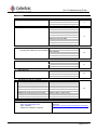
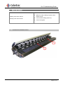
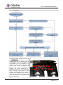
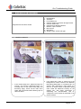
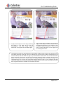
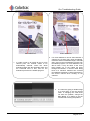
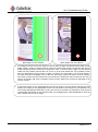
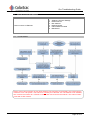
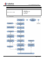
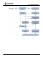
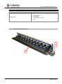
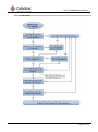
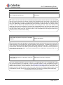
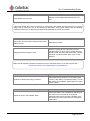
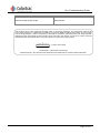
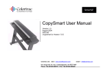
Gx+TSG Issue 5 Colortrac Ltd Gx+ Troubleshooting Guide Page 1 of 17 Date: 20/02/14 This is a confidential controlled document and is the property of Colortrac Ltd. It is not to be copied or reproduced in part or whole. It is intended for staff to read. SmartLF Gx+ Scanner Troubleshooting Guide Gx+ Troubleshooting Guide SmartLF Gx+ Scanners Troubleshooting Guide Issue 5 ©Colortrac Ltd 2014 No part of this product or publication may be reproduced, copied or transmitted in any form or by any means without permission from: Technical Support, Colortrac Ltd. Units 3 – 5 Brunel Court. Burrel Road. St Ives, Huntingdon, Cambridgeshire, PE27 3LW. United Kingdom. Tel: +44 (0)1480 464618 Fax: +44 (0)1480 464620 www.colortrac.com The product and the contents of this publication may be changed without prior notification. Colortrac Ltd makes every effort to ensure this publication is free from errors. Misprints, errors or quality observations should be reported to Technical Support, Colortrac Ltd. Colortrac Ltd shall not be liable for any damages, errors, issues or events that result from the use of the equipment or this manual. Page 2 of 17 Gx+ Troubleshooting Guide OVERVIEW Common Faults 1. Noise From Scanner 2. 3. 4. 5. 7. Image Doesn't Look Like It Should Cannot Connect Via Ethernet Including 'Error Ethernet 100' message Cannot Connect Via USB Dead Scanner Miscellaneous Issues. Including: Start / Stop During Scan. Paper Guide Assembly does not open… Paper Guide Assembly does not raise… Paper Guide Assembly not level Scans couple of inches the returns…. Image goes black during the scan. Media won’t load when trying to insert. Display is stuck in the ‘initialise’ state. Scanned Image Wrong Length. References within this Instruction Manual: The Gx+ Service Manual can be found on: www.colortracsupport.com User: colortrac Password: available on request Possible Cause Main drive roller rubbing on paper sensor bracket screw. Loose screws holding paper tray. Page 4 Normalisation. Autostitch Focus difference. Camera cables not through ferrites. Camera cable loose. Cameras from different batches. Diffusion Tape not fitted Dirty mirrors. Dirty glass. Strand or fibre across scan gap 6 Software / Scanner Settings Ethernet Driver. Mac Address. Network Speed. Internal Ethernet Cable Main Board 10 USB Cable Internal USB Cable PC USB Port Main Board 11 Control Board Main Board Control Board ID Chip PSU 13 PC Speed.. Faulty Gas Pistons. Main Board incorrectly configured Raising Lid Timing Belt loose. Software old version. LED’s turning off too early. Ribbon cable, control board…. Main Board needs replacing Wrong Motor Speed. 15 The firmware, driver and software updates can be found on: http://www.colortrac.com/support/software-downloads/ Page 3 of 17 Gx+ Troubleshooting Guide 1. Noise From Scanner Fault Possible Cause Vibrating noise from scanner. 1. Main drive roller rubbing on paper sensor bracket screw. 2. Loose screws holding paper tray. Clunking noise from scanner. 3. Loose Timing Belt. 1.1 SUGGESTED PROBLEM AREAS 1 2 Page 4 of 17 Gx+ Troubleshooting Guide 1.2 FLOW GRAPH A clunking noise coming from the Lid Assembly when the scanner is passing media through can be caused by the “Lid Timing Belt Tension Unit” (if fitted). If the Timing Belt in the Lid Assembly is too loose the Tension bar raises up and ‘clucks’ down as the belt tightens and loosens. This can be resolved by loosening the screws holding the 4 x brackets holding both the Hold Down Roller and the Pinch Roller in place, moving the brackets as far apart as possible, and retightening the screws. It adds enough tension in the belts to over come this issue. See the service manual for more information. Hold Down Belt Tension Bar Page 5 of 17 Gx+ Troubleshooting Guide 2. Image Doesn't Look Like It Should Fault Possible Cause Image doesn't look like it should 1. 2. 3. 4. 5. 6. 7. 8. 9. 10. 2.1 Normalisation. Autostitch Focus difference. Camera cables not put back through ferrites. Camera cable loose. Cameras from different batches. Diffusion Tape not fitted Dirty mirrors. Dirty glass. Strand or fibre across scan gap IMAGE EXAMPLES Media skews in scanner Image has a blue or yellow tint to background 1. If the media skews as it passes through the scanner, and causes a distorted image, it is normally down to the rollers being dirty and becoming slippy. Clean all the main drive rollers with an alcohol based cleaning wipe to clean off all dirt. 2. If an image has a blue or yellow tint to the background it could be down to the diffusion tape being badly fitted, or not fitted at all. If it accures after configuring a main board, it is down to an earlier version of plotworks being used. Install the Plotworks currently on the support site, and follow instructions in overwriting the executionable, and reconfiqure the main board as described in the service manual. Page 6 of 17 Gx+ Troubleshooting Guide Line caused by normalising in dirt Line caused by dirt on glass 3. A light, see-through line is normally caused by dirt being on the glass at the time of normalisation, and then being cleaned afterwards. Clean glass and normalise again. 4. A line that is solid, but fades in and out at the edges, is normally dirt in the scan path. Clean the glass and normalise. If it is still there, then it could be under the glass or even on the mirror. Follow instructions on the support site on cleaning the mirrors. 5. Lines down an image can also be down to fine strands of fibre across the scan gap. Use a torch to see clearly down the scan gap. First, open the lid fully and remove the glass, as described in the service manual, and look down the gap. Any loose strands of fibre seen can be removed with a pair of tweezers. The mirrors can also be checked out while the glass is removed, and any loose fibres on the mirrors can be 'blown' away but simply blowing across and down the gap. If a compressed air can is used, then test before blowing down the gap, as any moisture that also comes out will go on the mirrors and affect the images. Mirrors can be clean by using a soft cotton bud, but great care has to be taken not to scratch the mirror. Page 7 of 17 Gx+ Troubleshooting Guide Stitch difference Colour difference 1. If a step is seen in an image at one or more camera point, the scanner needs to be automatically stitched. Insert the white autostitch target with the lined side down and the horizontal lines in first, and run the autostitch process in the utilities program. 2. If a colour difference can be seen between 2 cameras, the scanner may need normalising. Insert the white normalisation target, matt side down, and run the normalisation process from the utilities program. If a colour difference can still be seen, it may be down to the focus being slightly out, or the cables not going through the ferrittes; a camera cable being loose or a tolerance between two cameras from difference batches. Follow instructions in the service manual when working on the cameras. 3. If a camera is giving a double image it is more likely to be the camera cable. If changing the cable does not solve the problem, change the Main Board. It is unlikely to be the camera itself causing the problem Page 8 of 17 Gx+ Troubleshooting Guide 1 Bad Image over one camera 2 Black image over one camera 4. If an image is incorrect over one camera, it can be down to either the camera board, cable or main board. Image 1 shows an image typical of a loose or broken cable, image 2 is typical of the camera board being the problem, but this is not always the case. To find out which, swap over the camera cable from the problem camera with one next to it, at the main board end. If the problem moves with the cable swap it is the camera or cable, if it stays in the same place, it is the main board. If the cable looks to be damaged or any of the core are broken, replace the cable. If it is the camera, first check to make sure the camera has not moved so it is looking off centre of the scan line. If the camera is still tight and does not appear to have moved, replace the camera as described in the service manual. 5. If the media scans, but no image appears, this can be down to the main board. Change the main board and configure to the appropriate model. The main board is more likely to be the problem, but if the image still appears blank after a scan, then check the cameras are all working. One camera can bring the others down to give a blank image, try unplugging each cable individually to see if the other camera start to see an image. Page 9 of 17 Gx+ Troubleshooting Guide 3. Cannot Connect Via Ethernet Fault Possible Cause Cannot connect via Ethernet. 3.1 1. 2. 3. 4. 5. 6. Software / Scanner Settings Ethernet Driver. Mac Address. Network Speed. Internal Ethernet Cable Main Board FLOW GRAPH NOTE: If the scanner powers up with 'Error Ethernet 100' message on the display, this is because the network is not a 1Gb system. The scanner is not likely to be the fault. If a 1Gb network is not available, then connect the scanner to a 1Gb hub or switch and connect that to the network. The scanner ONLY works with a 1Gb network. Page 10 of 17 Gx+ Troubleshooting Guide 4. Cannot Connect Via USB Fault Possible Cause Cannot connect via USB 1. 2. 3. 4. 4.1 USB Cable Internal USB Cable PC USB Port Main Board FLOW GRAPH Page 11 of 17 Gx+ Troubleshooting Guide Page 12 of 17 Gx+ Troubleshooting Guide 5. Dead Scanner Fault Possible Cause Dead Scanner 1. 2. 3. 4. 5.1 Control Board Main Board Control Board ID Chip PSU SUGGESTED PROBLEM AREAS 3 1 2 Page 13 of 17 Gx+ Troubleshooting Guide 5.2 FLOW GRAPH Page 14 of 17 Gx+ Troubleshooting Guide 7. Miscellaneous Issues Fault Possible Cause Start / Stops During Scanning PC Speed The scanner can be caused to stop and wait during scanning when the PC buffer is full of information, and has to empty it enough to continue receiving more information from the scanner. The scanner will stop and start if the PC is not of a good enough specification to keep up with the information being sent. TIFF RGB images creates large files and a lot of information, and the scanner can stop a number of times if the PC cannot cope with the information flow. During the start / stop of the scanner, the image can lose a line of information or corrupt a line of information due to the motor and roller moving very slightly at that point. To prevent this, the scanner software has a scan speed, which can be set to slow the scanner down so the PC can keep up with it. This will lengthen the scanning time taken, but it is down to the PC, not the scanner ability. Fault Possible Cause Paper Guide Assy does not open to it's maximun elevation. Faulty Gas Pistons If the Gas Pistons loose gas through the seal developing a leak, the Gas Piston will not push the Paper Guide Assembly to its full height when opened. Replacing the Gas Piston, by following the instructions in the service manual, will solve this problem. During early production of the Gx+, a manufactor error meant that the Gas Pistons were fitted up side down during production. This did not cause problems for most scanners and can be easily correctly by following the field modification instructions that can be found in the service manual. Fault Possible Cause Paper Guide Assy does not raise when using the control buttons Main Board incorrectly configured There are 2 different settings for the Gx+ scanners, a 'T' (raising lid) and a 'non-T' (standard lid) model. The main board needs to be confiqured to suit the appropriate model by using the PlotWorks program. Installing the program from the Gx+ page of the www.colortracsupport.co.uk site and run from the PC attached to the scanner. This will allow the correct version to be configured to the main board. This program looses all settings, so take a note of the motor speed from the utilities program before running the PlotWorks program, and re-insert the value afterwards, as well as normalising and autostitching. Full instructions in the service manual. Page 15 of 17 Gx+ Troubleshooting Guide Fault Possible Cause Paper Guide Assy not level Raising Lid Secondary Main Belt loose at one end. If the Paper Guide Assy does not sit level on the scanner, then media will skew and give an incorrect image, this is casued by one of the Raising Lid Secondary Timing belts being loose and slipping. Follow the instructions on aligning the Paper Guide Assembly in the service manual Fault Possible Cause Scan to file; Scanner scans couple of inches then returns to front. Software old version Image goes black during the scan. LED’s are turning off too early during a scan, needs firmware v1.38 or higher. If latest firmware already install, the LED’s may be at fault, check to see which one doesn’t flash when ‘scan’ is first pressed. Make sure all software, firmware and drivers are up to the latest version as on the Colortrac site. http://www.colortrac.com/support/support_downloads.htm Fault Media won’t load when trying to inserted. Fault Display is stuck in the ‘initialise’ state. Possible Cause The ribbon cable from the Main Board to the Control Board may be loose or not making good contact. If the cable is connected properly, it could also be the Control Board, paper sensors or paper sensor cables. Possible Cause This is normally caused by stopping the firmware download before it has completed. If switching off the scanner for a count of 20 seconds and switching back on does not fix the problem, then the other way to solve this issue is to change the main board. Page 16 of 17 Gx+ Troubleshooting Guide Fault Possible Cause Scanned Image Wrong Length Motor Speed* *The scanner has a 'motor speed' set internally, which is set during production. This controls the speed of the motor during scanning to compensate for tolerances in the Drive Roller and Motor Drive Pulley. This is to make sure the image length is correct in comparison to the original. Sometimes, particularly if the main board has been changed and the motor speed for that scanner has not been set in the scanner, it may not be correct. Using the following equation will help calculate a new motor speed to compensate for inaccuracies: 1 Measured Length Actual Length x current motor speed Actual length = a document of known size Measured length = the scanned known sized document measured top to bottom within ScanWorks. Page 17 of 17