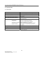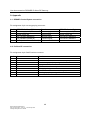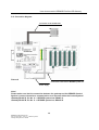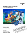
1
Dräger REGARD Profibus-DP Gateway User documentation REGARD Profibus-DP Gateway Part-Number: AG00485 Issue 4 - 13. February 2007 Dräger Safety AG & Co. KGaA Revalstraße 1 23560 Lübeck (Germany) Telefon +49 (451) 882-4147 Telefax +49 (451) 882-4991 User documentation REGARD Profibus-DP Gateway CONTENTS 1. For your safety .......................................................................................................................... 2. Introduction ................................................................................................................................ 2.1. Intended Use......................................................................................................................... 2.2. Description ............................................................................................................................ 2.3. Note ........................................................................................................................................ 3. Data transmission .................................................................................................................... 3.1. Input data ............................................................................................................................... 3.2. Output data ........................................................................................................................... 3.3. Data exchange ...................................................................................................................... 4. Installation .................................................................................................................................. 4.1. Control cabinet installation ................................................................................................ 4.2. Equipotential bonding connection ................................................................................... 4.3. Power supply ........................................................................................................................ 4.4. REGARD Control-System connection ............................................................................ 4.5. Profibus-DP connection ..................................................................................................... 4.6. Shielding connection ........................................................................................................... 4.7. Connection diagram ............................................................................................................ 5. Configuration............................................................................................................................... 5.1. Profibus-DP ........................................................................................................................... 5.1.1. Rotary coding switch “Profibus-ID High and Low“ ................................................ 5.1.2. Slide switch “Termination Profibus“ ......................................................................... 5.2. Serial interface RS232/RS485 ..................................................................................... 5.2.1. Rotary coding switch “S4 + S5 (RS485-ID)“ .......................................................... 5.2.2. Slide switch “Interface (RS485/RS232)“ ............................................................... 5.2.3. Slide switch “Termination (RS485 ON/OFF)“ ....................................................... 5.3. REGARD Control-System .................................................................................................. 5.4 . Select REGARD protocol .................................................................................................. 5.4.1. Profibus-DP configuration data ................................................................................. 5.4.2. Serial interface data RS232/RS485 ........................................................................ 6. Visual indication ........................................................................................................................ 6.1. LED “BUS Error“ .................................................................................................................. 6.2. LED “BUS Power“ ................................................................................................................ 6.3. LED “BUS State“ .................................................................................................................. 6.4. LED “Power“ .......................................................................................................................... 6.5. LED “State“ ............................................................................................................................ 6.6. LED “Error No / Select ID“ ................................................................................................ 7. Error handling ............................................................................................................................ 8. Technical data ............................................................................................................................ 8.1. Device data ............................................................................................................................ 8.2. Interface data ......................................................................................................................... REGARD Profibus-DP Gateway User documentation – Issue 4 – 13.February 2007 ©Dräger Safety AG & Co. KGaA 2 4 5 5 5 6 7 7 9 11 13 13 14 14 14 15 15 16 17 17 17 17 17 18 18 18 18 19 19 19 20 20 20 20 20 21 21 22 23 23 24 User documentation REGARD Profibus-DP Gateway CONTENTS 9. Appendix ...................................................................................................................................... 9.1. REGARD Control-System connection ............................................................................ 9.2. Profibus-DP connection ..................................................................................................... 9.3. Connection diagram ............................................................................................................ 9.4. Hexadecimal table ................................................................................................................ Regard Profibus-DP Gateway User documentation – Issue 4 – 13. February 2007 ©Dräger Safety AG & Co. KGaA 3 25 25 25 27 28 User documentation REGARD Profibus-DP Gateway 1. For your safety The law for governing technical work equipment (equipment safety law) requires to point out the following points 1): Strictly follow the Instructions for Use Any use of the REGARD Profibus-DP Gateway requires full understanding and strict observation of these instructions. The gateway is only to be used for the purposes specified hereunder. Maintenance At regularly time intervals a function test must be performed by qualified personnel (with log). Only qualified personnel is permitted to make any modifications. Use in hazadous areas The Regard Profibus-DP Gateway is not designed or certified to be installed or to be operated in hazardous areas. Liability for proper functioning or damage The liability for the proper function of the REGARD Profibus-DP Gateway is irrevocably transferred to the owner or operator to the extent that the gateway is serviced or repaired by personnel not employed or authorized by DrägerService or if the gateway is used in a manner not conforming to its specified use. Dräger Safety AG & Co. KGaA doesn´t take any liability for damages caused due to ignoration of the above mentioned advises. The warranty and liability provisions of the terms of the sale and delivery of Dräger Safety AG & Co. KGaA are likewise not modified by the recommendations given above. Dräger Safety AG & Co. KGaA 1) All references to laws, regulations and standards apply to the legal system of the Federal Republic of Germany. REGARD Profibus-DP Gateway User documentation – Issue 4 – 13.February 2007 ©Dräger Safety AG & Co. KGaA 4 User documentation REGARD Profibus-DP Gateway 2. Introduction 2.1. Intended Use The REGARD Profibus-DP Gateway provides a Profibus-DP fieldbus coupling for the REGARD Control-System of Dräger Safety AG & Co. KGaA and enables the access to informations about the current status of alarms, faults, maintenance messages and critical failures as well as the current gas concentrations of all REGARD channel cards (e.g. 4.20mA-, SE-EX-, HART- cards....) for a REGARD Control-System. In addition to that the gateway provides the possibility to acknowledge alarms and faults for a single or all cards as well as putting single or all cards into command mode to inhibit alarms. For the proper operation of the REGARD Profibus-DP Gateway a REGARD Master card is necessary. 2.2. Description As a base for the REGARD Profibus-DP Gateway the universal fieldbus gateway UNIGATE of the company Deutschmann Automation GmbH was selected. In the standard version this gateway adapts a serial interface RS232/RS485 to the Profibus-DP according to the standard EN 50170. In this version the data are transferred transparenctly. In order to consider the special protocol characteristics of the REGARD Control-System and at the same time to ensure a significant figure of the transferred information on the Profibus-DP field bus, the software of the gateway was redesigned by the manufacturer following the specifications of the Dräger Safety AG & Co. KGaA. REGARD Control-Systems with up to 99 REGARD channels are supported by a REGARD Profibus-DP Gateway using the REGARD Master card. The REGARD Profibus-DP Gateway operates only as a Slave on the internal serial REGARD system bus and even thus it can not read or send data direct to REGARD channel cards. This function is taken over by the REGARD Master card in a REGARD Control-System. The Master card queries cyclically all channel cards for status (alarms, faults, maintenance messages and critical failures) and the current gas concentrations. For a REGARD ControlSystem the cycle time to query 99 channnels for status is approx. 2.2 sec. and approx. 10 sec. for the gas concentration The gateway analyses all information about status and gas concentrations of the channel cards and stores the data accordingly sorted to the channel card number in a internal buffer. With each renewing query of the Master card the data already available in the buffer are updated. Regard Profibus-DP Gateway User documentation – Issue 4 – 13. February 2007 ©Dräger Safety AG & Co. KGaA 5 User documentation REGARD Profibus-DP Gateway After every query cycle for the status of the channel cards, so after 2.2 sec, the Master card queries also the gateway for data (alarm acknowledge, command mode and alarm inhibit) for overtaking into the REGARD Control-system. If data is available, it will be overtaken by the Master card and passed on to the channel card, which will then execute the function. On the Profibus-DP fieldbus the REGARD Profibus-DP Gateway behaves likewise only as a Slave. An attached standard-conformal Profibus-DP master, e.g. a PLC/DCS, can interrogate only information from one channel card at a time. In order to achieve this the Profibus-DP master has to transmit first a channel card number to the gateway. There upon the gateway places the requested information of the selected channel card from the buffer into the data output register and the Profibus-DP master can read in the data now by a query. In addition to the data for status and gas concentration also the channel card number is supplied by the gateway. Thus the Profibus-DP master is put into the position to determine whether the information of the selected channel is already present (valid), or whether the gateway still provides information for a channel out of a query taken place before (data validation). In order to enter the data of all channels cards in a REGARD Control-System, the attached Profibus-DP master must query all channel cards cyclically. Up to 32 users, transmitter and receiver, can be summarized on the Profibus in a line structure. Thus there is the possibility to setup a very complex distributed system with the REGARD Profibus-DP Gateway that consist, e.g. of a PLC/DCS as a Profibus-DP master and a connection of up to 31 separate REGARD Control-Systems with up to 99 REGARD channels (theoretical upper limit). There is also the possibility to integrate a REGARD Control-System with attached REGARD Profibus-DP Gateway into an already existing Profibus fieldbus network. 2.3. Note The available operating manual to the REGARD Profibus-DP Gateway describes all substantial functions of the gateway and deals in particular with the installation, the configuration and the operation of the gateway with the REGARD Control-System. If you should need further information about the universal field bus gateway UNIGATE, please refer to the provided original user manual of the company Deutschmann Automation GmbH. REGARD Profibus-DP Gateway User documentation – Issue 4 – 13.February 2007 ©Dräger Safety AG & Co. KGaA 6 User documentation REGARD Profibus-DP Gateway 3. Data transmission By an attached Profibus-DP master the current status of the alarms A1, A2, A3 and Fault, Transmitter/Measuring head calibration, alarm inhibit, critical failure, timeout and the current gas concentration with sign, decimal places and measuring range exceeding of each channel card can be queried. Additionally a Profibus-DP master is able to acknowledge alarms and faults of single or all channel cards as well as activating the command mode. If the command mode is activated automatically alarms will be inhibit. The complete functionality of the gateway is linked to the Profibus-DP with 3 byte input data and 10 byte output data. 3.1. Inputdata Card number 1 to 99 for channel cards, 100 for Master card, 101 to 109 for Extra-Master cards or 127 for all channel cards, Master- and Extra-Master cards. 2. Byte 000e lcqr r = 0/1 ⇒ reset flag „new status“. q = 0/1 ⇒ alarm acknowledge. c = 0/1 ⇒ command mode and alarm inhibit without lock (up to 10 minutes). l = 0/1 ⇒ command mode and alarm inhibit with lock (permanent). e = 0/1 ⇒ end command mode and alarm inhibit. 3. Byte* 0000 0def f = 0/1 ⇒ maintenance password for command mode. e = 0/1 ⇒ configuration password for command mode. d = 0/1 ⇒ service password for command mode. * All flags in the 3rd byte can be set optional with flags „c“ and „l“ in the 2nd byte ! 1. Byte 0sss ssss Description: 1. Byte: Selection of the REGARD channel card by the channel card number, 1 up to max. 99, for querying of status and gas concentration (see Item 3.2 output data). In the 2nd and 3rd byte additional flags can be set, which will activate functions at the selected channel card. Functions for the Master card shall be activated by selecting card number 100, for ExtraMaster cards 101 to 109 and for all cards (channel cards, Master- and Extra-Master cards) by 127. This selection will only return the card number in the 1st byte in the output data. The flag „t“ for timeout in the 7st byte is only relevant for the Master card. All other flags in the output data will be set to „0“. Regard Profibus-DP Gateway User documentation – Issue 4 – 13. February 2007 ©Dräger Safety AG & Co. KGaA 7 User documentation REGARD Profibus-DP Gateway 2. Byte: Flag „r“ ⇒ Reset flag „n“, new status, in the 2nd byte of the output data. Flag „q“ ⇒ Acknowledge alarms. Flag „c“ ⇒ Activates the command mode and the alarm inhibit without lock. The cards will return into the normal operation mode automatically after 10 minutes. The cards can also be reset to normal operation mode before expiration of 10 minutes by setting flag „e“. Optional the command mode can be activated with password for maintenance, configuration and service. To do this one of the flags „f“, „e“ or „d“ must be set. If the command mode is activated without password all configuration parameters of the card can only be read. Flag „l“ ⇒ Activates the command mode and the alarm inhibit with lock. The cards will not return into the normal operation mode automatically and must be reset by setting flag „e“. Optional the command mode can be activated with password for maintenance, configuration and service. To do this one of the flags „f“, „e“ or „d“ must be set. If the command mode is activated without password all configuration parameters of the cards can only be read. Flag „e“ ⇒ Exits the command mode and the alarm inhibit. Note ! In the 2nd byte all flags only triggers functions, if they are changing from „0“ to „1“. If there is more then one flag set, only the flag with the highest priority will be considered where flag „r“ has the highest priority and flag „e“ has the lowest priority. All flags in the 2nd byte of the input register will remain in this status and they must be reset to „0“ after the function is executed to activate a specific function again. 3. Byte: Flag „f“ ⇒ The command mode will be activated with maintenance password. Flag „e“ ⇒ The command mode will be activated with configuration password. Flag „d“ ⇒ The command mode will be activated with service password. Note ! All flags in the 3rd byte are optional parameters for the activating of the command mode with flag „c“ and „l“ in the 2nd byte. If there is more then one flag set, only the flag with the highest priority will be considered where flag „f“ has the highest priority and flag „d“ has the lowest priority. All flags in the 3nd byte of the input register will remain in this status and they must be reset to „0“ after the function is executed to activate a specific function again. REGARD Profibus-DP Gateway User documentation – Issue 4 – 13.February 2007 ©Dräger Safety AG & Co. KGaA 8 User documentation REGARD Profibus-DP Gateway 3.2. Output data 8. Byte* Card number 1 to 99 for channel cards, 100 for Master card,101 to 109 for Extra-Master or 127 for all cards. 0000 000n n = 0/1 ⇒ new status (A1, A2, A3, fault, Transmitter/Measuring head calibration, alarm inhibit, critical card fault, timeout). 0000 0111 111 = 000/010 ⇒ Alarm1 (A1) off. 111 = 001/011/101/111 ⇒ Alarm 1 (A1) un-acknowledged. 111 = 100/110 ⇒ Alarm 1 (A1) acknowledged, but still activ. 0000 0222 222 = 000/010 ⇒ Alarm 2 (A2) off. 222 = 001/011/101/111 ⇒ Alarm 2 (A2) un-acknowledged. 222 = 100/110 ⇒ Alarm 2 (A2) acknowledged, but still activ. 0000 0333 333 = 000/010 ⇒ Alarm 3 (A3) off. 333 = 001/011/101/111 ⇒ Alarm 3 (A3) un-acknowledged. 333 = 100/110 ⇒ Alarm 3 (A3) acknowledged, but still activ. 0000 0fff fff = 000/010 ⇒ Fault (FLT) off. fff = 001/011/101/111 ⇒ Fault (FLT) un-acknowledged. fff = 100/110 ⇒ Fault (FLT) acknowledged, but still activ. 0000 tcih h = 0/1 ⇒ Transmitter-/Measuring head calibration (H-cal.). i = 0/1 ⇒ Alarm inhibit. c = 0/1 ⇒ critical failure. t = 0/1 ⇒ Timeout. 00mm mmmm 00mmmmmm= High byte for gas concentration 9. Byte* nnnn nnnn 1. Byte 2. Byte 3. Byte 4. Byte 5. Byte 6. Byte 7. Byte 0sss ssss nnnnnnnn= Low byte for gas concentration dd = 00/01/10/11 ⇒ 0/1/2/3 decimal places. f = 0/1 ⇒ measuring range exceeded. s =0/1 ⇒ negative sign * Byte 8 and byte 9 can also read in by the Profibus-DP Master as „Word“ value ! 10. Byte 0000 sfdd Description: 1. Byte: Channel card number, 1 to max. 99, for the available data in bytes 2 to 10 for status and gas concentration. With the channel card number it´s possible for the Profibus-DP master to determine whether the information of the selected channel is already present (valid), or whether the gateway still provides information for a channel card of a query taken place before (data validation). For card number 100 only the flag „t“ for timeout in the 7st byte is relevant. All other flags in the output data will be set to „0“. 2. Byte: Flag „n“ ⇒ The status in the byte 3 to 7 has changed against the last query of this channel card. If this flag is set, then all flags in byte 3 to byte 7 has to be evaluated again. This flag remains in it´s status until it´s reset with flag „r“ in the 2nd byte of the input data. 9 Regard Profibus-DP Gateway User documentation – Issue 4 – 13. February 2007 ©Dräger Safety AG & Co. KGaA User documentation REGARD Profibus-DP Gateway 3. Byte: Flags „111“ ⇒ With 3 flags the status of the 1st alarm (A1) will be shown. Depending on the alarm configuration of the channel card different flags will be set for an identical alarm status ! 4. Byte: Flags „222“ ⇒ With 3 flags the status of the 2st alarm (A2) will be shown. Depending on the alarm configuration of the channel card different flags will be set for an identical alarm status ! 5. Byte: Flags „333“ ⇒ With 3 flags the status of the 3st alarm (A3) will be shown. Depending on the alarm configuration of the channel card different flags will be set for an identical alarm status ! 6. Byte: Flags „fff“ ⇒ With 3 flags the status of the fault (FLT) will be shown. Depending on the alarm configuration of the channel card different flags will be set for an identical alarm status ! 7. Byte: Flag „h“ ⇒ The transmitter/measuring head connected to the channel card has turned into calibration mode. Flag „i“ ⇒ The channel card is turned into the status alarm inhibit. Alarms will be inhibit, if the transmitter/measuring head connected to the channel card is turned into command mode or a fault alarm is triggered. Flag „c“ ⇒ A critical failure has occurred at the channel card. For critical failures also a fault (FLT) occures. Flag „t“ ⇒ A timeout has occured for the selected channel or Master card. No current data for status and gas concentration is available, because the channel card is not connected to the control system or the card is not configurated correctly. With Master cards the card is not connected to the control system or the card is not configurated correctly. 8. Byte: High-byte for measuring value of the gas concentration. 9. Byte: Low-byte for measuring value of the gas concentration. Note ! Byte 8 and byte 9 can also read in by the Profibus-DP Master as „Word“ value ! 10. Byte: Flags „dd“ ⇒ Shows the decimal places for the measurement of the gas concentration. Flag „f“ ⇒ Measuring range exceded has occured. Flag „s“ ⇒ The measurement of the gas concentration has a negative sign. REGARD Profibus-DP Gateway User documentation – Issue 4 – 13.February 2007 ©Dräger Safety AG & Co. KGaA 10 User documentation REGARD Profibus-DP Gateway 3.2. Data exchange The following flowchart shows in a simple form the cyclically data exchange between a ProfibusDP Master and the REGARD Profibus-DP Gateway. The activation of functions for all channel cards, Master cards or Extra-Master cards is not included in this flowchart. start Initialising MaxChannelCards = 99, ChannelCard = 1 N Alarm acknowledgement ? N Command mode ? End command mode ? Y initialising gateway input data: channel card, alarm acknowledge, flag „q“ = „1“ Y initialising Gateway input data: channel card, command mode and alarm inhibit, flag „c“ or flag „l“ = „1“ send gateway input data read gateway output data evaluate measuring value of gas concentration: high- and low-byte, decimal places, measring range exceeded, sign 1 2 Regard Profibus-DP Gateway User documentation – Issue 4 – 13. February 2007 ©Dräger Safety AG & Co. KGaA N 11 Y initialising Gateway input data: channel card, end command mode and alarm inhibit, flag „e“ = „ 1“ User documentation REGARD Profibus-DP Gateway 1 2 N new status flag „n“ < 1? evaluate status: A1, A2, A3, fault, calibration, alarm inhibit, critical failure, timeout Y initialising gateway input data: reset flag „n“ of output data with flag „r“ = „1“ of input data. send gateway input data initialising gateway input data: new status, alarm acknowledge, command mode and alarm inhibit, password, all flags = „0“ send gateway input data N ChannelCard <MaxChannelcards ? Y ChannelCard = ChannelCard +1 REGARD Profibus-DP Gateway User documentation – Issue 4 – 13.February 2007 ©Dräger Safety AG & Co. KGaA ChannelCard = 1 12 User documentation REGARD Profibus-DP Gateway 4. Installation Picture 1 4.1. Control cabinet installation The gateway has been developed for use in a control cabinet use, IP20, and therefore it must be mounted on a standard top hat-rail (deep top hat-rail according to EN 50022). • • Engage the gateway modul from the top in the top-hat rail and swivel it down until the module engages in position. Above and below the gateway modul must be at least 5 cm clearance for heat dissipation. Regard Profibus-DP Gateway User documentation – Issue 4 – 13. February 2007 ©Dräger Safety AG & Co. KGaA 13 User documentation REGARD Profibus-DP Gateway 4.2. Equipotential bonding connection • Connect the standard top hat-rail (deep top hat-rail according to EN 50022) with as low impedance as possible to the equipotential bonding strip of the control cabinet (see Item 4.7/Picture 2). Use a flexible earthing wire with a cross-section of at least 10mm2 for this. • Fit an earthing terminal to the top-hat rail directly next to the gateway-module. The earthing terminal automatically establishes an electrical connection to the top-hat rail. • The gateway connection to the equipotential bonding is automatically established via the integrated earthing connection in the left part of the device when it is put on the DIN-rail. 4.3. Power supply The gateway operates with a supply voltage of 10,8V–30V DC (nominal 24V DC). The connection of the supply voltage is routed via the 5-pin screw-type plug connector (see also Item 4.4 and Item 4.7 /Picture 2). 4.4. REGARD Control-System connection The serial interface connection of the REGARD Profibus-DP Gateway to the internal REGARD system bus is routed via the 5-pin screw-type plug connector (see also Item 4.7/Picture 2). Use a flexible shielded cable with at least 3 wires (for example LiYCY 3x0,25) for this. Pin assignment: 5-pin screw-type plug connector Pin No. 1 2 3 4 5 REGARD Profibus-DP Gateway Power supply 24V/DC Power supply 0V RX / RS485- (RS485 B) TX / RS485+ (RS485 A) GND (connection to Pin No. 2) Function Power supply Power supply Receive signal Transmit signal Reference for Pin 3 + 4 REGARD Control-System Power supply 24V/DC Power supply 0V Internal Bus RS485 B Internal Bus RS485 A -------------------------------------------- The cable shield has to be connected to the earthing connection terminal (equipotential bonding) next to the gateway module (see also Item 4.7/Picture 2). REGARD Profibus-DP Gateway User documentation – Issue 4 – 13.February 2007 ©Dräger Safety AG & Co. KGaA 14 User documentation REGARD Profibus-DP Gateway 4.5. Profibus-DP connection The connection of the REGARD Profibus-DP Gateway to the Profibus-DP is routed via the 9-pin Sub-D socket (see also Item 4.7/Picture 2). Use only cable which is certified for Profibus-DP applications. Pin assignment: 9pin Sub-D socket Pin No. 1* 2 3 4 5 6 7 8 9 Name Shield* B M5 P5 A - Function Shield* Non-inverting input/output signal from Profibus DGND – data reference potential 5V supply voltage Inverting input/output signal from Profibus - * The shield of the Profibus cable is connected to the equipotential bonding system via an RCnetwork. This guarantees higher interference immunity of the gateway module since the cable shield current which may be up to a few Amperes owing to potential differences between two bus users is not discharged via the device. 4.6. Shield connection The shield signal for the electronic circuitry is connected to the DIN-rail via the integrated earthing connection in the left part of the device. The shield of the Profibus cable must be directly linked up to the 9-pin Sub-D socket connector (see also Item 4.5) and is connected to the equipotential bonding system via an RC-network. This guarantees higher interference immunity of the gateway module since the cable shield current which may be up to a few Amperes owing to potential differences between two bus users is not discharged via the device. Regard Profibus-DP Gateway User documentation – Issue 4 – 13. February 2007 ©Dräger Safety AG & Co. KGaA 15 User documentation REGARD Profibus-DP Gateway 4.7. Connection diagram Connection to the Profibus-DP Picture 2 Connection to the internal REGARD system bus Power supply Note ! Please make sure, that the connection between the gateway and the REGARD ControlSystem is correct, otherwise a communication error occures within the Control-System ! Gateway RS485 A, Pin No. 4 -> REGARD system bus, RS485 A. Gateway RS485 B, Pin No. 3 -> REGARD system bus, RS485 B. REGARD Profibus-DP Gateway User documentation – Issue 4 – 13.February 2007 ©Dräger Safety AG & Co. KGaA 16 User documentation REGARD Profibus-DP Gateway 5. Configuration 5.1. Profibus-DP The gateway features 3 switches to set the Profibus-ID and the Bus-Termination: Rotary coding switch, Profibus-ID High Rotary coding switch, Profibus-ID Low Slide switch “Termination“ Profibus-DP ID (High byte) Profibus-DP ID (Low byte) Switchable Profibus-DP termination resistor 5.1.1. Rotary coding switch “Profibus-ID High und Low“ These two switches are used to set the Profibus-ID (00..7D) of the gateways in hexadecimal notation. A conversion table from decimal to hexadecimal can be found in the appendix. This value is read only once when the gateway is activated and cannot be changed via the Profibus. In case of changing the position of the rotary coding switches the gateway must be switched off and switched back on again. 5.1.2. Slide switch “Termination Profibus“ If the gateway is operating as the first or last physical device in the Profibus-DP, there must be a bus termination at the gateway. In order to do this, either a bus terminating resistor must be activated in the connector or the resistor (220Ω) integrated in the gateway must be activated. In order to do this, move the slide switch to position „ON“. In all other cases, the slide switch must remain in the position „OFF“. For further information on the subject of bus termination please refer to the general Profibus literature. 5.2. RS232/RS485 interface The gateway features 4 switches to set the RS232/RS485 interface, the RS485-ID and the BusTermination: Rotary coding switch S4 Rotary coding switch S5 Slide switch “Interface“ Slide switch “Termination“ Regard Profibus-DP Gateway User documentation – Issue 4 – 13. February 2007 ©Dräger Safety AG & Co. KGaA RS485-ID (High byte) RS485-ID (Low byte) Switch to select RS485 or RS232 interface Switchable RS485 termination resistor 17 User documentation REGARD Profibus-DP Gateway 5.2.1. Rotary coding switch “S4 + S5 (RS485-ID)“ These two switches are used to set the RS485-ID of the gateway in hexadecimal notation. Operating the gateway with the REGARD Control-System switch „S4“ and „S5“ must be set to position „0“. In case of maintenance (see also Item 5.4) the gateway has to be brought to the configuration mode by setting the switches „S4“ and „S5“ to the position „F“. The setting is read in only once when the gateway is activated. In case of changing the position of the rotary coding switches the gateway must be switched off and switched on again. 5.2.2. Slide switch “Interface (RS485/RS232)“ This switch is used to select whether the gateway is running with the REGARD Control-System or in the configuration mode in case of maintenance (see also Item 5.4). Running the gateway with the REGARD Control-System the switch „Interface“ must be set to position „RS485“. For running the configuration mode to position „RS232“. 5.2.3. Slide switch “Termination (RS485 ON/OFF)“ If the gateway is operated as the first or last physical device in the internal RS485 bus of the REGARD-Control-System, there must be a bus termination at this gateway. In order to do this, either a bus terminating resistor in the connector or the resistor integrated in the gateway (150Ω) must be activated. To activate the integrated resistor the slide switch „Termination“ must be set to position „ON“. In all other cases, the slide switch must remain in position „OFF“. For further information on the subject of bus termination please refer to the general RS485 literature. If the integrated resistor is used, please consider that this automatically activates a pull-down resistor (390Ω) to ground and a pull-up resistor (390Ω) to VCC. 5.3. REGARD Control-System On all cards of the REGARD Control-System the communication checksum has to be configured to „CRC“. For further information on this subject please refer to the user documentation for the REGARD Control-System. REGARD Profibus-DP Gateway User documentation – Issue 4 – 13.February 2007 ©Dräger Safety AG & Co. KGaA 18 User documentation REGARD Profibus-DP Gateway 5.4. Select REGARD protocol On delivery the protocol software (see also Item 2.2) for the REGARD Control-System, adapted by the company Deutschmann Automation GmbH, is already loaded into the REGARD ProfibusDP Gateway and the parameters for the serial interface to the REGARD Control-System are already preconfigured (see also Item 5.4.2). Note ! A configuration by using the software Wingate which comes as a standard accessory is not required and only in case of maintenace or service it´s necessary to do this ! In case of maintenance or service the gateway has to be brought to the configuration mode. For this the switches S4 and S5 have to be set to position „F“ and the switch „Interface“ has to be set to position „RS232“. Next a connection to the PC serial port has to be established and the gateway has to be started once more. The program Wingate automatically selects the interface parameters correctly. For the operation of Wingate please take a look at the Wingate Online help. 5.4.1. Profibus-DP configuration parameter The configuration parameter of the gateway for the Profibus-DP master connection can be load via the GSD file which comes on disk as a standard accessory. • • • • • • Configuration data: in acc. with GSD file, module „DRAEGER (REGARD Vers. 20) 3E/10A“ „DRAEGER (REGARD Vers. 21) 3E/10A“, starting with serial number 28540259 Diagnostic data: max. 8 byte Baud rate: automatic detection up to 12 MBaud Sync: supported Freeze: supported Ident. No.:0x2079 5.4.2. Serial interface parameter RS232/RS485 The following parameters for the serial interface to the REGARD Control-System are already preconfigured and only in case of maintenance or service the parameters must be reconfigured by using the software Wingate which comes on disk as a standard accessory (see Item 5.4). • • • • • Start bit: 1 Data bits: 8 Stop bit: 1 Parity: None Baud rate: 4800 Baud Regard Profibus-DP Gateway User documentation – Issue 4 – 13. February 2007 ©Dräger Safety AG & Co. KGaA 19 User documentation REGARD Profibus-DP Gateway 6.1. Visual indication The gateway features 9 LEDs with the following significance: LED Bus Error LED Bus Power LED Bus State LED Power LED State LED Error No / Select ID red green red/green green red/green yellow Profibus error Profibus supply voltage Interface status, Profibus DP RS485/RS232 supply voltage Interface status, RS485/RS232 Binary display of the connection to the REGARD channel number (address) /error number Note ! In the configuration mode these displays are not valid and only meant for internal use. 6.1. LED “Bus Error“ These LED is activated directly by the Profibus ASIC and signals that the Profibus is not in “DATA EXCHANGE” status. 6.2. LED “Bus Power“ This LED is directly connected to the electrically isolated supply voltage of the Profibus end. 6.3. LED “Bus State“ Lights green Flashes green Flashes green/red Lights red Profibus in Data Exchange status Gateway waiting for Profibus configuration data Gateway waiting for Profibus parameter data General Profibus error 6.4. LED “Power“ This LED is directly connected to the (optionally also electrically isolated) supply voltage of the RS485/RS232 end. REGARD Profibus-DP Gateway User documentation – Issue 4 – 13.February 2007 ©Dräger Safety AG & Co. KGaA 20 User documentation REGARD Profibus-DP Gateway 6.5. LED “State“ Lights green Flashes green Flashes green/red Lights red Flashes red Data exchange active via RS485/RS232 RS485/RS232 ok, but no permanent data exchange No data exchange since switching on General gateway error (see LED’s Error No.) Gateway is in configuration mode 6.6. LED “Error No. / Select ID“ If these 4 LEDs flash and LED “State“ simultaneously lights red, the error number is displayed in binary notation (conversion table, see appendix) in accordance with the table of Chapter "Error handling". Otherwise, the card number with which communication is currently operating via the RS232/RS485 interface is displayed also in binary notation. Regard Profibus-DP Gateway User documentation – Issue 4 – 13. February 2007 ©Dräger Safety AG & Co. KGaA 21 User documentation REGARD Profibus-DP Gateway 7. Error handling If the gateway modul detects an error, the error is signalled by the red lighting “State“ LED and simultaneously the error number being indicated by means of “Error No.“ LEDs as shown in the table below. In addition, this error number is transfered as an external diagnostic byte via the Profibus to the Master. A distinction can be made between two error categories: Serious errors (1-5): In this case, the gateway must be switched off and switched back on again. If the error occurs again, the gateway modul must be exchanged and returned for repair. Warnings (6-15): These warnings are displayed for one minute simply for information purpose and are then automatically reset. If such warnings accure frequently, please inform the DrägerService. In the configuration mode these displays are not valid and only meant for internal use. LED8 LED4 LED2 LED1 0 0 0 0 0 0 0 0 0 0 1 1 0 0 1 1 0 0 0 1 0 1 0 1 Error no. resp. ID 0 1 2 3 4 5 0 0 1 1 1 1 1 1 1 1 1 1 0 0 0 0 1 1 1 1 1 1 0 0 1 1 0 0 1 1 0 1 0 1 0 1 0 1 0 1 6 7 8 9 10 11 12 13 14 15 Error descrition Reserved Initialisation error of the RS485/RS232 interface EEROM error Stack error Hardware fault of the fieldbus ASIC Configuration error of the gateways (unknown protocol) Reserved RS485/RS232 transmit buffer overflow RS485/RS232 receive buffers overflow Timeout on reception RS485/RS232 interface Transmit error of the RS485/RS232 interface Receive error of the RS485/RS232 interface Adressing error of the RS485/RS232 interface Configuration error by the Profibus-Master General error of the RS485/RS232 interface Internal error Table 1: Error handling REGARD Profibus-DP Gateway User documentation – Issue 4 – 13.February 2007 ©Dräger Safety AG & Co. KGaA 22 User documentation REGARD Profibus-DP Gateway 8. Technical data 8.1. Device data Device data: Location: External power supply Current consumption Power supply at the Profibus interface Protection Environment conditions Temperature: Atmospheric pressure: Relative humidity: Enclosure Housing size Weight Approvals Regard Profibus-DP Gateway User documentation – Issue 4 – 13. February 2007 ©Dräger Safety AG & Co. KGaA Control cabinet, Top-hat rail mounting (35mm) 10,8 to 30V DC (24V DC nominal) at 24V DC: typ. 120 mA, max. 150 mA ; at 10,8V DC: typ. 350 mA 5V DC / max. 50 mA Reverse voltage protection, short circuit protection, overload protection 0 bis +60°C with forced convection, 0 bis +40°C without forced convection 795 bis 1080 hPa during operation, 660 bis 1080 hPa during storage and transport 5 % bis 80 % , no condensation, no corrosive atmosphere IP 20 90 x 127 x 55 mm (WxHxD) / 5 x 7 x 6“ (WxHxD) 0,3 Kg CE mark: elektromagnetic compatibility, Profibus certification 23 User documentation REGARD Profibus-DP Gateway 8.2. Interface data Interface data: Interface designation Physical interface Standard Profibus-DP RS-485 EIA-Standard REGARD RS-485 EIA-Standard Symmetrical Asynchronous serial half-duplex Symmetrical Asynchronous Serial half-duplex Transmission method Number of users : -> Difference signal Master / Slave 32 Transmitters 32 Receivers Bus topology Line -> Difference signal Master / Slave 1 REGARD Control-System with REGARD Master card and up to 99 REGARD channels. Line Data rate 4,8 kBits/s Max.: 12 MBits/s Standard: 9,6 kBits/s, 19,6 kBits/s, 93,75 kBits/s,187,5 kBits/s, 500 kBits/s,1,5 MBits/s, 3 MBits/s, 6 MBits/s,12 MBits/s 1200m Max.: 1200m Baud rate-dependent: 93,75 kBd -> 1200m, 500 kBd -> 500m, > 1,5 MBd -> 100m Transmission mode Cable length REGARD Profibus-DP Gateway User documentation – Issue 4 – 13.February 2007 ©Dräger Safety AG & Co. KGaA 24 User documentation REGARD Profibus-DP Gateway 9. Appendix 9.1. REGARD Control-System connection Pin assignment: 5-pin screw-type plug connector Pin No. 1 2 3 4 5 REGARD Profibus-DP Gateway Power supply 24V/DC Power supply 0V RX / RS485- (RS485 B) TX / RS485+ (RS485 A) GND (connection to Pin No. 2) Function Power supply Power supply Receive signal Transmit signal Reference for Pin 3 + 4 REGARD Control-System Power supply 24V/DC Power supply 0V Internal Bus RS485 B Internal Bus RS485 A -------------------------------------------- 9.2. Profibus-DP connection Pin assignment: 9-pin Sub-D socket connector Pin No. 1* 2 3 4 5 6 7 8 9 Name Shield* B M5 P5 A - Regard Profibus-DP Gateway User documentation – Issue 4 – 13. February 2007 ©Dräger Safety AG & Co. KGaA Function Schield* Non-inverting input/output signal from Profibus DGND – data reference potential 5V supply voltage Inverting input/output signal from Profibus - 25 User documentation REGARD Profibus-DP Gateway 9.3. Connection diagram Connection to the Profibus-DP Picture 2 Connection to the internal REGARD system bus Power supply Note ! Please make sure, that the connection between the gateway and the REGARD ControlSystem is correct, otherwise a communication error accures within the Control-System ! Gateway RS485 A, Pin No. 4 -> REGARD system bus, RS485 A. Gateway RS485 B, Pin No. 3 -> REGARD system bus, RS485 B. REGARD Profibus-DP Gateway User documentation – Issue 4 – 13.February 2007 ©Dräger Safety AG & Co. KGaA 26 User documentation REGARD Profibus-DP Gateway 9.4. Hexadecimal table Hex 0 1 2 3 4 5 6 7 8 9 A B C D E F Decimal 0 1 2 3 4 5 6 7 8 9 10 11 12 13 14 15 Binary 0000 0001 0010 0011 0100 0101 0110 0111 1000 1001 1010 1011 1100 1101 1110 1111 Regard Profibus-DP Gateway User documentation – Issue 4 – 13. February 2007 ©Dräger Safety AG & Co. KGaA 27 User documentation REGARD Profibus-DP Gateway Draeger Ltd Kitty Brewster Industrial Estate Blyth Northumberland NE24 4RG England +44 1670 352891 Fax +44 1670 356266 Beijing Fortune Draeger Safety Equipment Co.,Ltd. Jixiang Lu, B Area Beijing Tianzhu Airport Industrial Zone Houshayu, Shunyi County Beijing 101300, P.R. China +86 10 69498000 Fax +86 10 69498006 Dräger Safety AG & Co. KGaA Revalstraße 1 D-23560 Lübeck Germany +49 451 882-2794 Fax +49 451 882-4991 Draeger Industrie S.A. 3c, route de la Fédération F-67025 Strasbourg Cedex France +33 388 407676 Fax +33 388 407667 Draeger Safety, Inc. P.O. Box 120 Pittsburgh, PA 15 230 U.S.A. +1 412 787 8383 Fax +1 412 787 2207 Draeger South East Asia Pte, Ltd. 67, Ayer Rajah Crescent #06-03 SGP-0513 Singapore Singapore +65 872 92 88 Fax +65 773 20 33 http://www.draeger.com REGARD Profibus-DP Gateway User documentation – Issue 4 – 13.February 2007 ©Dräger Safety AG & Co. KGaA 28