1
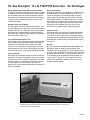
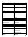
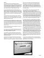
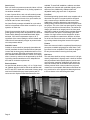
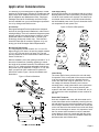
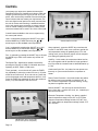
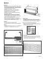
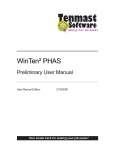
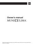
Architects and
Engineers Manual
Packaged Terminal Air Conditioners
and Heat Pumps
STANDARD FEATURES COMPARISON
Remington, GE, Amana, Carrier and Friedrich
Features
Infrared Wireless Capability
Sleep Timer Capability
Automatic “Cool Dry” Humidity Control
“Rapid-Heat”/”Rapid-Cool” Technology
Extended Feature Touch Pad Controls w/LED
Digital Temperature Set Point
Universal Heaters/Power Connection
Solid State Thermostat
Concealed Manual Vent Control
Up-Front Cleanable Filter
Automatic Indoor Frost Control
Corrosion Treated Chassis
Two Position Bi-Directional Discharge Grill
Fan Motors
Fan Cycle Switch
Fan Only Setting – 2 speed
Indoor Fan Speed
Automatic Freeze Protection
Temperature Limiting
Remote Control Thermostat Compatibility
“Front Desk” Control Interface
Service Indicator LED
Self Diagnostics
Automatic Emergency Heat
Quick Heat Recovery
Auto (Random) Restart/Power Recovery
NIM PC Interface Module
GE
REMINGTON
PTAC Series
Deluxe 2500
Dry Air 25
Deluxe 3500
Premium 5500
Standard
Standard*
Standard
Standard
Standard
Standard
Standard
Standard
Standard
Standard
Standard
Standard
Standard
2
Standard
Standard
Hi/Low
Standard
Electronic
Standard
Standard
Standard
Standard
Standard
Standard
Standard
Standard
–
–
–
–
–
–
–
Standard
Standard
Standard
Standard
Option
Standard
2
Standard
Standard
Hi/Low
Standard
Electronic
Standard
Standard
–
–
–
–
Standard
–
–
–
–
–
–
–
–
Standard
Standard
Standard
Standard
Option
Standard
2
Standard
Standard
Hi/Low
Standard
Electronic
Standard
Standard
–
–
–
–
Standard
–
–
–
–
–
–
–
–
Standard
Standard
Standard
Standard
Option
Standard
2
Standard
Standard
Hi/Low
Standard
Electronic
Standard
Standard
–
–
Standard
Standard
Standard
–
–
–
–
–
Standard
Standard
Standard
Standard
Standard
Standard
Standard
–
Standard
2
Standard
Standard
Hi/Low/Auto
Standard
Elect. 7-Step
Standard
Standard
Standard
Standard
Standard
Standard
Standard
–
Amana Carrier Friedrich
PTC/PTH Model 52P P Series
–
–
–
–
–
–
–
–
–
–
–
–
–
–
Standard
Option
Standard
Standard
Standard
Standard
–
Option
Option
Option
Standard
Standard
1
1
Standard
Standard
1 Speed
1 Speed
Hi/Low
Hi/Low
Standard
Option
Electronic Mechanical
Standard
Option
Standard
Option
Standard
–
Standard
–
Standard
Standard
–
–
Standard
–
–
–
–
–
–
–
–
–
–
–
Standard
Standard
–
Option
Standard
1
Standard
1 Speed
Hi/Low
–
Mechanical
Option
Option**
–
–
Standard
–
–
–
This comparison is based on publicly available information believed to be accurate and current at the time of publication. * Requires purchase of specific Touch Pad to enable ** Requires purchase of additional Field Mounted Kit
NOMENCLATURE
MODEL
PTAC
07
B
208
R
REMINGTON
PTAC=Packaged Terminal Air Conditioner
(Cooling with Electric Heat)
PTHP = Packaged Terminal Heat Pump
COOLING CAPACITY (BTUH)
VOLTAGE
07 = 7,000
09 = 9,000
208/230 - 1 Phase
265 - 1 Phase
12 = 12,000
15 = 15,000
VINTAGE DESIGNATION
#110511303
© 2003 McQuay International
Packaged Terminal Air Conditioners and Heat Pumps
Chassis Fits Any Standard
16"H x 42"W x 133/4"D
Wall Sleeve
Solid State Electronic
Touch Pad Controls
High Efficiency
Refrigeration Coils
Vibration Isolated
Rotary Compressor
Bi-Directional
Discharge Grille
Fan Cycle Control
Attractive, Durable
Polymer Front Panel
Solid State
Thermostat/Freeze Sensor
Removable / Cleanable Filters
Front Desk
Control Connection
Electronic Control Pads / Optional Remotes
Universal Heater/
Power Cord
Table of Contents
Introduction........................................................pages 1-2
Our Advantages ................................................pages 3-4
Features & Benefits................................................page 5
Engineering Guide Specifications ....................pages 6-8
Application Considerations ....................................page 9
Controls ................................................................page 10
Options ................................................................page 11
Performance & Electrical Data ............................page 12
Wiring Diagrams ..................................................page 13
Wall Sleeve Installation ........................................page 14
Drain Kit Installation ............................................page 15
Unit Dimensions ..................................................page 16
Page 1
Introduction...Packaged Terminal Air Conditioning
At Remington®, innovation is more than a mission, it’s
our history. It began in 1955, when we developed the
first through-the-wall, self-contained heating and cooling
system for individually-zoned applications. It was an
invention that revolutionized the heating and cooling
industry.
Architectural Design Freedom
Eliminates the need for large mechanical equipment
rooms, which helps increase potential leasable space.
Expensive ductwork is also eliminated, so the floor to
floor distances can be reduced without lowering ceiling
heights.
When it was first introduced, the Incremental® System, or
Packaged Terminal Air Conditioning (PTAC) as it's known
today, was a new concept, built on the premise that by
using a small air conditioning unit in each space, multizone buildings could be heated and cooled more efficiently and at lower first costs versus using an expensive
central plant. This major breakthrough made a
lasting impact.
Comfort on Demand
Each occupant determines their own comfort requirements for their space. By using Remington units, occupants can easily cool one room while simultaneously
heating another without continuously operating a central
chiller and central boiler.
Since that first Incremental System was introduced,
hundreds of thousands of Packaged Terminal Air Conditioners and Heat Pumps(PTHP) have been installed in
all types of buildings, all over North America. Residents,
employees, students, visitors and more now enjoy yearround comfort in a host of multi-room, multi-story buildings such as hotels/motels, office buildings, apartments,
dormitories, hospitals, nursing homes and schools.
Advantages of a "PTAC"
Lower First Cost
There is no need to pay for expensive ductwork, a central chiller/boiler plant or the miles of piping that are
required with central systems. This can significantly
reduce both design and installation costs. Capital costs
can also be reduced by providing a unit to the space
only when it becomes occupied.
Lower Design Costs
The overall system design is greatly simplified, allowing
designers to devote more time to other areas and
reducing overall costs.
Page 2
Inherent Economy
Installing PTAC/PTHP units reduces the need to condition the entire building to provide comfort in one space.
For example, with this type of system, comfort conditioning can be provided in one area for an occupant working
after hours, while the rest of the building sleeps.
Easy Maintenance Without Disruption
Packaged Terminal products require minimal maintenance because of their simple design and high-quality
construction. Routine maintenance can be easily performed by a facility's own staff. If a unit becomes
inoperable, it can be repaired or replaced without
disruption of adjacent spaces. The easy, slide-in, slideout chassis allows one person to quickly remove and
replace an inoperable unit, minimizing downtime in the
effected space.
The new Remington PTAC/PTHP unit has revolutionized
the industry with its superior options and innovations,
bringing you the highest quality air conditioners in the
industry, year after year.
The New Remington® 16 x 42 PTAC/PTHP Series Unit...Our Advantages
Energy Savings Beyond Energy Efficiency Rating (E.E.R.)
The Digital Temperature Set Point allows each occupant
to easily set their precise desired zone comfort temperature. Eliminating the zone comfort guesswork inherent
with mechanical knob controls decreases unnecessary
running of the unit and helps prevent expensive overcooling/overheating.
Standard Flexible Control Module
The Remington unit has a flexible control module. This
allows the digital control pad to be removed and mounted within the room on a wall within the occupied space.
Additionally, the standard features and functionality of
the controls are a superior value versus the mechanical
knobs most other PTAC's use.
Corrosion Resistant Hydrophilic Coils
On Remington units, all evaporator and condenser coils
are protected with a hydrophilic coating. This feature is
standard on all Remington units, making it an ideal
choice for any environment, including highly corrosive
environments such as Florida. This protection can also
extend the life of your coils, offering added cost savings.
Classroom Benefits
Remington units' standard features provide exceptional
benefits for classroom applications. There are no knobs
for students to remove and lose. Remington's two-motor
units are inherently quieter than a single motor design.
The Remington unit is pencil proof. The Fresh Air
Damper also arrives without additional labor required to
enable the damper.
Extra Humidity Control
Remington is the only AC manufacturer to offer the CoolDry Dehumidification Mode standard on all units. The
system is designed to provide high indoor air quality
(IAQ) by reducing humidity which can help to prevent
mold/mildew build-up in conditioned space. As a result,
the conditioned air will feel and smell fresher, removing
up to 70% more humidity in the Cool-Dry mode when
compared to the standard cool mode at 50% load.
Results will vary under different loading conditions.
A Superior Choice
Remington units meet the industry standard (ASHRAE
90.1) for E.E.R.’s and capacities, and they offer much
more than that. Our money-saving operational features,
combined with our superior warranty packages, can pay
dividends both in labor savings and operational costs in
the long run.
Warranty
No other manufacturer stands behind their product like
Remington. Both our Gold Plus and Platinum Plus
Packages offer a limited one-year unit exchange warranty on the entire conditioner and a refrigeration circuit unit
exchange warranty for the 2nd through 5th year. The Gold
Plus package offers an additional functional parts warranty for the 2nd through 5th year. Freight costs will be
paid by the manufacturer. Please contact us for more
warranty package details.
Remington's contemporary design is both attractive and thoughtful - with standard
features like solid-state electronic touch pad controls that are easy to operate and
provide precise comfort settings.
Page 3
Remington® Air Conditioning...Our Advantages
Remington PTAC/PTHP are quiet, energy efficient products that provide greater flexibility to meet zoned heating
and cooling requirements. They are the perfect choice
for new or replacement projects.
Touch Pad Controls
For new projects: The Remington PTAC/PTHP products
give you the flexibility to design your overall system the
way you want it. Units are available with cooling and
electric resistance heat or heat pump operation. Multiple
sizes and voltage ratings allow you to match the heating,
cooling and electrical requirements of each application
and each zone. Remington's all-in-one unit or wallmounted touch pad control and remote control interface
gives you the flexibility to choose the control scheme
that best fits your requirements. All control schemes can
be selected on-site.
For replacement projects: Remington conditioners are
easy to install and maintain and will fit any standard
16"H x 42"W x 133/4"D wall opening.
Infrared
Sensor
• Remington conditioners are compatible with most
existing wall thermostats and remote control interfaces
for added savings on installation labor and costs.
• Insulated wall sleeve is constructed of heavy-gauge,
zinc-coated, phosphatized steel, with welded joints
and polyurethane based powder coating for maximum
durability and corrosion resistance.
• Standard 16"H x 42"W x 133/4"D dimensions.
• Factory welded slide channels facilitate easy
installation and removal of chassis.
• Predrilled to align with chassis mounting screws
and simplify installation.
• Separate shipment of wall sleeve is available to
avoid damage to the chassis during construction.
A waxed weather panel is provided to keep out the
elements until the chassis arrives.
• Sleeve extensions are available for competitors’
shallow wall sleeve applications (111/2"D) that do not
conform to industry standard depth (133/4"D).
Remington PTAC/PTHP
Page 4
LED Indicator
Lights
Digital Temperature
Set Point
Wall Sleeve (Indoor View)
42"
16"
133/4"
Features and Benefits
Remington® PTAC/PTHP
What it does for you
Solid state electronic touch pad controls
Reliable and easy to use.
Digital temperature set point and LED indicator lights
Provides room occupants with exact comfort setting and
continuous unit operating status.
"Cool-Dry" humidity control
Automatically controls humidity (when selected) for improved comfort
and better indoor air quality. This feature can add 70% more
dehumidification than the normal A/C operation.
Rapid-Heat™ and Rapid-Cool™ technology
Allows the unit to quickly bring room to comfort conditions at start-up while
reducing cycling. Saves wear and tear on compressor.
Sleep Option
Raises or lowers room temperature by several degrees for guest
comfort and energy savings.
Timer Option
Automatically controls unit shut-off after a specified time
(1 to 15 hours).
Temperature Electronic Limiting
Adjustable minimum and maximum room temperature set points.
Infrared capable
Allows wireless remote control of all units
(wireless remote controller optional).
Universal electric heater
Provides flexibility to select among three heater sizes and amperage
ratings (power cord ordered separately).
Dual fan motors
Provides quiet operation and lower operating costs.
Compressor time-delay restart
Reduces wear and tear for extended life.
Automatic random restart
Helps avoid overloading electrical circuits in the event of a
power outage.
Solid-state thermostat/freeze sensor
Provides precise temperature control and automatically senses and
responds to low temperatures to protect against freeze conditions.
Standard interface for front desk control
Allows easy connection to energy management or front desk control.
All-in-one unit or wall-mounted touch pad
Provides flexibility to choose unit or remote control without purchasing
a separate thermostat (optional wiring kit is required).
Cooling with electric resistance heat or heat pump operation in
multiple sizes, capacities, and voltages.
Provides flexibility to match application requirements and the
requirements of each zone.
Industry standard 16"H x 42"W x 133/4"D wall sleeve dimension
Simplifies design for new construction and is compatible with most
existing wall sleeves for easy, low cost replacements.
Multiple fan speed settings
Provides quiet, economical operation.
Fan cycle control
Allows continuous or fan cycle operation.
High efficiency refrigeration coils with hydrophilic coating
Provides maximum efficiency and corrosion resistance.
Up-front, cleanable filters
Easily accessible filters can be cleaned without removing the
front panel.
Vibration isolated rotary compressor
More efficient, quieter, and more reliable than reciprocating
compressors.
Manual control outside air damper
Can be opened for fresh air operation or closed tight to recirculate
room air and conserve energy.
Bi-directional indoor air discharge grille
Allows airflow to be directed where it is needed most.
Attractive, durable polymer front cover
Complements any room décor and maintains its "like new"
appearance under demanding conditions.
Wall Stat/controller option
Compatible with most 24V wall thermostats.
LED Diagnostics
Unit self-diagnostics.
Page 5
Engineering Guide Specifications - Remington® Model
General
Furnish packaged terminal (air conditioners) (heat
pumps) of the sizes and capacities shown on the schedule and/or specifications. The units shall be located as
shown in the drawings and each shall include wall
sleeve, outdoor louver, heating/cooling chassis, front
panel and subbase (optional 208/230v).
All units shall be ETL and CETL listed for safety and
ARI certified for capacity and performance. Units shall be
Remington® Model designated with prefix (PTAC) (PTHP)
or equal.
Overall dimensions for the basic unit (excluding louver)
shall not exceed 42" wide, 16" high and 203/4" deep.
Standard wall sleeve dimensions shall not exceed 16"
high, 42" wide and 133/4" deep. Units furnished with an
electrical subbase shall not exceed 42" wide, 20" high
and 203/4" deep.
Units shall be designed to operate on (208/230)
(265/277) volts, 60 Hz, single-phase power.
The E.E.R. shall be from 11.6 to 9.2 and COP from 3.4
to 2.8.
Heating/Cooling Chassis
Chassis shall be slide-in, plug-in type with a self-contained, hermetically sealed refrigerant circuit. All
chassis sheet metal parts shall be coated with a polyester based powder paint or galvanized for maximum
corrosion resistance.
The chassis shall consist of the following components:
vibration isolated, permanent split capacitor rotary-type
compressor, rifled copper tubed evaporator and condenser coils with high efficiency raised lance aluminum
plate fins that are hydrophilic coated to resist corrosion
and mechanically expanded to the tubes for maximum
heat transfer and a capillary restrictor type refrigerant
metering device. Coils shall be factory tested at 300 psig
(heat pump models shall also include reversing valve
and charge balancing device).
A positive-closing, manual fresh air damper shall be
included within the chassis to provide the option of fresh
air during operation.
System airflow shall be accomplished by the use of the
separate outdoor and indoor fan motors. Motors shall be
permanent split capacitor, totally enclosed and permanently lubricated. A single speed motor shall directly
drive the outdoor fan. The outdoor fan shall be constructed out of high impact resistant polymer and consist of
multiple propeller-type blades with a slinger ring
designed to efficiently remove condensate. The indoor
Page 6
fan assembly shall consist of a single centrifugal fan that
is forward curved and directly connected to a two-speed
motor. All fans shall be statically and dynamically balanced to provide for quiet and smooth operation.
During the cooling cycle, the compressor and both fan
motors shall be energized. Condensation accumulated
on the indoor coil shall be drained into the outdoor
section of the unit where it is to be picked up by the outdoor fan and transferred to the outdoor coil where it
shall then be evaporated to enhance units' capacity and
efficiency.
(Electric Resistance Heat Only Models) During the
heating cycle, only the indoor fan motor and the electric
resistance heaters are energized. The compressor shall
not be energized. Heaters shall be high mass cal-rod
type with high limit cutout. Electric resistance heaters
shall be universal in design such that the type of power
cord specified with the heating/chassis determines the
respective heater size as shown in the schedule and/or
specifications. Electric resistance heaters must be located behind the indoor coil and must not be visible or
accessible through the indoor discharge grille.
(Reverse Cycle Heat Pump Models) During the heating
cycle, the reversing valve, compressor and both fan
motors will be energized. Depending on the outdoor air
temperature, two distinct heating modes shall be available. Namely, compressor only or electric heat only.
Minimum outdoor temperature for compressor operation
shall be 25°F. Between outdoor temperature of 25°F and
45°F, the compressor and electric heater will alternate as
required to maintain indoor temperature. When the outside temperature is below 25°F, the electric heat-only
mode shall be utilized. The electric heaters shall be high
mass cal-rod type with high limit cutout. Electric resistance heaters shall be universal in design such that the
type of power cord specified with the heating/chassis
determines the respective heater size as shown on the
schedule and/or specifications. Electric resistance
heaters must be placed behind the indoor evaporator coil
and must not be visible or accessible through the indoor
discharge grille. Condensation accumulated on the outdoor coil during reverse cycle heating MUST not be
evaporated against the indoor coil as it could contaminate the indoor air with pollutants and odors.
Condensation accumulated during reverse cycle heating
shall transfer from chassis into wall sleeve by means of a
thermostatically controlled drain valve. Condensate shall
exit wall sleeve via weep holes or optional indoor/outdoor
drain kit.
Controls
The controls shall utilize solid-state electronics.
Operation of the unit shall be controlled through the use
of a touch-pad. The touch-pad shall use no knobs and
shall be liquid tight for easy care and cleaning. The control shall incorporate digital display of temperature settings, allowing precise comfort selection by user.
when room is brought to set point temperature after
being off for 2 or more hours. This will automatically
compensate for the cold or warm radiation effect felt
from the mass in the walls, floor, and furnishings until
they normalize. The 2°F offset is maintained for the first
cycle only. After that, the setting reverts to that shown on
the digital display.
The touch-pad shall include an ON/OFF selector, a
MODE selector that will enable the user to select HEAT,
COOL, Cool/Dry or FAN only operation; a FAN selector
that allows high or low speed fan operation; and a TEMP
selector to allow for precise room temperature adjustment.
The unit shall have two cooling modes (COOL and
COOL/DRY). The Cool/Dry feature shall be
Owner/Facility Manager activated or deactivated by an
internal dipswitch and when activated, be user selectable
through the touch-pad control. When the Cool-Dry mode
is selected, the control algorithm shall slightly extend the
run time of the compressor and low fan without significantly changing the room temperature from the user set
point. This feature shall increase dehumidification by up
to 70% when compared to the standard Cool mode.
Operation/mode of the unit shall be easily confirmed
through the use of LED status lights and a soft confirming beep sound. The LED status lights must be visible
with the control door closed.
The electronic controls shall allow the Owner/Facility
Manager to establish the maximum and minimum temperature range for heating and cooling modes (electronic
temperature limiting).
The touch-pad shall be interchangeable and upgradeable with an optional touch-pad that includes Sleep and
Timer functions and shall also be compatible with an
optional wireless infrared remote with these functions.
When the optional touch-pad is present, pressing the
Sleep button shall activate the Sleep feature. The Sleep
mode shall improve comfort and reduce energy consumption by gradually raising the room temperature by
3.6°F from the set-point over two hours in cooling mode,
or lowering the room temperature by 5.4°F over 2 hours
in the heating mode. Pressing the Timer button shall activate the Timer feature. Each press of the button shall
increase and display the timer setting in hours from 1 to
15. When the timer is activated when the unit is operating, the unit shall shut off at the selected time interval.
When the unit is off and the timer is activated the unit
will come on at the selected time interval in the control
settings (Mode/Fan/Temperature) that were last set on
the unit.
Unit shall have automatic temperature compensating
algorithm (+2°F in HEAT or –2°F in COOL) to minimize
temperature swing and compressor cycling during period
In the event of a malfunction the control shall provide
self-diagnostics and display an error code to allow easy
identification of service required.
The touch-pad shall be designed to be easily removed
from the heating/cooling chassis and mounted to a wall
for remote control without the need or cost of separately
purchased wall-mounted controls. The unit shall retain all
of its features regardless if the touch-pad is mounted on
the wall or unit.
The touch-pad shall be infrared capable for control via
wireless remote controller.
The controls shall incorporate a standard interface for
low voltage connection to dry contacts at a central control or energy management system.
Page 7
Controls (cont.)
Each unit shall incorporate an automatic indoor coil frost
control to extend compressor life by limiting operation in
low ambient conditions.
available. To ease field installation, subbase must have
adjustable side channels with predrilled adjusting holes
and score lines. Additionally, subbase shall have
adjustable leveling legs each with 1" adjustment.
In case of power failure, each unit will randomly restart
when power resumes to avoid overloading and power
surging of the electrical circuits. Also, upon restart, the
unit shall retain its last control setting.
Front Panel
Each heating/cooling chassis shall come complete with a
decorative front panel. Front panel shall be designed
with a contoured top to facilitate airflow into the room.
Additionally, it shall be designed to wrap-around the
heating/cooling chassis and constructed of impact resistant polymer. The color of the front panel shall be Antique
Ivory as to match that of the wall sleeve. The airflow discharge grille shall be an integral part of the front panel
and shall be made of the same impact resistant polymer
material as the front panel. The discharge grille shall
consist of a single section and be designed to be twoposition reversible to customize the direction of airflow
out of the unit. Room side return air shall enter the heating/ cooling chassis through the louvered front panel.
An Owner/Facility manager selectable fan cycle switch
shall be incorporated to allow either continuous or cycle
operation of indoor fan.
Room freeze protection shall be incorporated to safeguard against freezing indoor temperatures and shall be
Owner/Facility Manager activated/deactivated. When
activated, if the indoor temperature drops to 40° F,
regardless of the control setting the electric heater and
indoor fan will automatically energize to prevent further
room temperature decline.
Outside Air Louvers
Outside air louvers shall be (stamped) (extruded architectural) anodized aluminum finished natural (stamped
louvers shall be heavy gauge anodized aluminum of no
less than 16 gauge). Extruded architectural louvers are
also available with baked enamel to match color chip by
others. Louvers by others must be approved by the heating/cooling chassis manufacturer as to adequate free
area and air circulation requirements.
Electrical Subbase
As specified and shown on plans, a 3" or 4" high electrical subbase shall be furnished. Electrical subbase shall
be ETL and CETL listed and constructed of heavy gauge
steel and finished with epoxy based powder paint to
resist corrosion. Optional fused disconnects are also
Page 8
Filtration
Room side return air shall be completely filtered through
permanent, washable polypropylene mesh filters. Foam
type filters are not acceptable. Filters shall be designed
for easy access without removing the front panel.
Wall Sleeve
The wall sleeve shall be entirely constructed of A-60 galvaneal, phosphatized, 18-gauge steel. It shall be finished
with polyurethane based powder paint to provide maximum corrosion protection. Additionally, the interior top
and side surfaces shall be insulated. Wall sleeves with
ordinary enamel finish or those made from polymeric
material are not acceptable. Wall sleeves shall have factory provisions for use of appropriate fastening devices
to secure sleeve to the wall through the sides.
Application Considerations
The following is a brief description of application considerations for the Remington Terminal Air Conditioners and
Heat Pumps. More detailed instructions are included in
IM719 Installation and Maintenance Data - Remington
Packaged Terminal Air Conditioners and Heat Pumps
and are available from your local Remington representative or by visiting www.HVACnow.com
Power Supply Wiring
All wiring must be done in accordance with all local and
National Electrical Code requirements. Time delay fuses
or HACR circuit breakers are required. The chassis has
a universal electric heater, so the kW is determined by
the field-installed power cord. Figure 2 shows the electrical receptacles for each power cord.
Unit Selection
Remington Packaged Terminal products are designed
and built for through-the-wall installation in either new or
existing buildings. Their self-contained refrigerant system
delivers cooling to the desired space. Heating is accomplished with electric resistance heat or reverse cycle
technology (heat pump models only). Final selection
should be made with an architect, engineer or by contacting your local Remington Sales Representative.
Figure 2. Electrical Receptacles
Wall Opening Requirements
The rough opening should measure 161/4"H x 421/4"W.
When using a louver frame, the opening should measure
165/8"H x 425/8"W (see figure 8 on page 14). The wall
opening should be clear of obstructions to allow the wall
sleeve to slide into it.
When a subbase is used, the opening must start 3" or 4"
above the finished floor (including carpeting) to match
the height of the subbase selected. The subbase is available in 3" or 4" heights and has adjustable leveling legs
that provide up to an additional 1" height. A 3" or 4" subbase is required for 265V models and is optional for
208V/230V models. Figure 1 shows the subbase and
dimensions.
Figure 1. Electrical Subbase
Control Wiring
The control pad is factory wired on the unit and ready
for operation. If the control pad will be remote mounted,
it can be removed from the unit, detached from the
control box and wired using an optional 20', 35' or 50'
low voltage wire harness accessory and a remote
mounting plate. A snap-in decorative cover replaces the
control pad on the unit. The mounting location (with
regard to cold drafts, discharge air, outside wall, etc.) is
not critical as the room temperature sensor remains on
the unit.
Remote Wall Thermostat
Units are compatible with most wall thermostats and a
remote thermostat can be installed by removing the control pad and wiring the remote thermostat to the control
box. A snap-in decorative cover replaces the control pad
on the unit. Mount the thermostat on an inside wall, away
from the unit discharge air stream. It is important to note
that if a remote wall thermostat is used, the standard
control features of the unit control pad (with the exception of "Remote on/off") will not be available unless the
wall thermostat used includes them.
Page 9
Controls
The system logic required to operate the Remington
Packaged Terminal Air Conditioners is factory wired and
ready to go when they arrive at your job site. Or, if you
prefer, units can be easily modified to accommodate the
control scheme that best meets your requirements. The
all-in-one digital control pad can be easily removed from
the unit for remote wall mounting. A standard interface
on the unit permits easy connection to energy management or central building control systems. Finally, a 24V
remote thermostat can be used in lieu of the control pad.
Control features available to the room occupant using
the control pad include:
Heat - is selected by pressing the ON/OFF key to ON
and the MODE key to HEAT and using the
or
arrow keys to set the standard room temperature.
Cool - is selected by pressing the ON/OFF key to ON
and the MODE key to COOL and using the
or
arrow keys to set the standard room temperature.
Fan - is selected by pressing the ON/OFF key to ON and
the MODE key to FAN. In this mode, only the fan will
operate.
Two Speed Fan - High/Low fan speed is selected by
pressing the FAN key to HIGH or LOW while the unit is
operating in HEAT, COOL or FAN mode.
Timer (optional) - to turn the unit off, press the TIMER
key repeatedly to select the number of hours (1-15) after
which the unit will turn off. To turn the unit on, preset the
unit to the desired mode and temperature and turn it off.
Press the TIMER key repeatedly to select the number,of
hours (1-15) after which the unit will turn on.
Unit Mounted Touch Pad
Sleep (optional) - press the SLEEP key to activate this
function. In the HEAT mode, over a two-hour period, the
unit temperature setting will gradually drop 5°F. In the
cooling mode, over a two-hour period, the unit temperature setting will gradually raise 4°F.
Cool/Dry - In this mode, the compressor indoor low fan
will cycle together and will operate for longer periods of
time to provide the increased rate of dehumidification up
to 70%.
Continuous/Cycle Fan - the indoor fan can operate continuously or cycle on and off with the compressor or
heater.
Room Freeze Protection - the electric heater and indoor
fan will be turned on as needed to maintain a 40°F to
50°F minimum temperature to prevent freezing, so long
as power is supplied to the unit.
Remote ON/OFF - the unit may be turned off and on
from a front desk, or with a time clock, etc., located up to
325 feet from the unit.
Electronic Temperature Limiting - the factory supplied
control temperature range is from 60°F to 85°F. Other
minimum temperature settings include 64°F, 68°F and
72°F. Other maximum temperature settings include 75°F,
78°F and 82°F.
Wall Mounted Touch Control Pad
(shown with optional sleep/timer)
Page 10
Options
Wall Sleeve
• Insulated wall sleeve is constructed of heavy-gauge,
zinc-coated, phosphatized steel, with welded joints
and polyurethane based powder coating for maximum
durability and corrosion resistance.
• Standard 16"H x 42"W x 133/4"D dimensions.
• Factory welded slide channels facilitate easy
installation and removal of chassis.
• Predrilled to align with chassis mounting screws
and simplify installation.
• Separate shipment of wall sleeve is available to
avoid damage to the chassis during construction.
A waxed weather panel is provided to keep out the
elements until the chassis arrives.
• Sleeve extensions are available for competitors
shallow wall sleeve applications (111/2"D) that do not
conform to industry standard depth (133/4"D).
Drain Kits
• Internal or external mounted drain kits.
• Pre-drilled wall sleeve simplifies drain kit installation.
Subbase
• Adjustable leveling legs comes in 3" or 4" height with
an additional 1-inch adjustment (see figure 3).
42"
16"
133/4 "
Outdoor Louvers
• Standard stamped aluminum louver (see figure 4)
• Extruded aluminum architectural louver (see figure 5)
• See inside back cover for color options on louvers
Wireless Infrared Remote Control (Optional)
• Requires only wireless remote controller. Unit comes
standard with infrared sensor.
Figure 3. Electric Subbase
Remotes (optional)
Louver Frames
• Mechanically attach wall sleeve to the wall for panel
wall construction jobs. Also trims exterior rough cut
wall openings for better appearance.
Figure 5. Extruded Aluminum Architectural Louver
Figure 4. Standard Stamped Aluminum Louver
Page 11
Performance & Electrical Data
General Product Data
UNIT SIZE
Voltage
07
Cooling w/Heat Pump
Cooling w/Electric Heat
Capacity (Btuh)
Cooling (1)
EER
Full Load Amps
Watts
Small
Watts
Btuh
Amps
Electric
Medium Watts
Heat (3)
Btuh
Amps
Large
Watts
Btuh
Amps
Capacity (Btuh)
Cooling
EER
Full Load Amps
Watts
Reverse
Btuh
Cycle
COP
Heat (2)
Full Load Amps
Watts
Minimum Small
Heater
Circuit Ampacity
Medium Heater
Large Heater
Time Delay Fuses Small Heater
or Type HACR
Medium Heater
Circuit Breaker
Large Heater
NEMA
Small Heater
Receptacle Type
Medium Heater
Required
Large Heater
208/230
7,400/7,500
11.5/11.3
3.1/3.0
643/664
1,500/1,900
5,115/6,479
7.5/8.5
2,300/2,800
7,843/9,548
11.3/12.4
7,100/7,400
11.6/11.5
3.1/2.9
612/642
6,600/6,800
3.4/3.4
2.8/2.6
562/581
9.4/10.6
14.1/15.5
15
15/20
6-15R
6-20R
-
09
265
7,400
11.3
2.5
652
1,900
6,479
7.4
2,800
9,548
10.8
7,300
10.7
2.6
680
6,800
3.2
2.4
622
9.3
13.5
15
15
7-20R
7-20R
-
(1) Based on ASHRAE and ARI test conditions of 95°F DB/75°F WB outdoor, 80°F
DB/67°F WB inside.
(2) Based on ASHRAE and ARI test conditions of 47°F DB outdoor, 70°F DB indoor.
(3) Electric Heating Amps includes indoor fan motor. Heater size is determined by the
power cord selection.
(4) The above data is subject to change.
Approximate Shipping Weights
Heating / Cooling Chassis and Front Panel
Size 007. . . . . . . . .
Size 009 . . . . . . . .
Size 012 . . . . . . . .
Size 015 . . . . . . . .
Cabinet Wall Sleeve
.
.
.
.
. . . . . . . . . . . . . . . . . . .140
. . . . . . . . . . . . . . . . . . .140
. . . . . . . . . . . . . . . . . . .145
. . . . . . . . . . . . . . . . . . .145
. . . . . . . . . . . . . . . . . . . .36
lbs.
lbs.
lbs.
lbs.
lbs.
Louvers
Flush-stamped . . . . . . . . . . . . . . . . . . . . . . . . .6 lbs.
Architectural . . . . . . . . . . . . . . . . . . . . . . . . . . .8 lbs.
Subbase
3" (76 mm) High Electrical . . . . . . . . . . . . . . . .10 lbs.
4" (102 mm) High Electrical . . . . . . . . . . . . . . .10 lbs.
Electrical Receptacle . . . . . . . . . . . . . . . . . . . . . .1 lb.
Plug Cord Cover . . . . . . . . . . . . . . . . . . . . . . . . .1 lb.
Power Cord . . . . . . . . . . . . . . . . . . . . . . . . . . . . .1 lb.
Page 12
208/230
8,900/8,900
10.6/10.4
4.1/3.9
839/855
1,500/1,900
5,115/6,479
7.5/8.5
2,300/2,800
7,843/9,548
11.3/12.4
8,900/8,900
10.6/10.4
4.1/3.9
841/856
8,400/8,500
3.3/3.2
3.6/3.5
755/768
9.4/10.6
14.1/15.5
15
15/20
6-15R
6-20R
-
12
265
8,900
10.4
3.3
856
1,900
6,479
7.4
2,800
9,548
10.8
8,900
10.4
3.3
859
8,500
3.2
2.9
776
9.3
13.5
15
15
7-20R
7-20R
-
208/230
11,200/11,600
10.1/10.0
5.4/5.1
1,109/1,160
1,500/1,500
5,115/5,115
7.5/7.5
2,300/2,800
7,843/9,548
11.3/12.4
3,800/4,700
12,958/16,027
18.5/20.7
11,000/11,400
10.0/9.9
5.5/5.1
1,105/1,157
11,000/11,400
2.9/2.9
5.4/5.0
1,115/1,147
9.4/10.6
14.1/15.5
23.1/25.9
15
15/20
25/30
6-15R
6-20R
6-30R
15
265
11,600
10.2
4.4
1,139
1,900
6,479
7.4
2,800
9,548
10.8
4,700
16,027
18.0
11,400
10.1
4.3
1,124
10,900
2.9
4.2
1,099
9.3
13.5
22.5
15
15
25
7-20R
7-20R
7-20R
208/230
14,000/14,500
9.4/9.4
7.3/6.9
1,489/1,543
1,500/1,500
5,115/5,115
7.5/8.5
2,300/2,800
7,843/9,548
11.3/12.4
3,800/4,700
12,958/16,027
18.5/20.7
14,000/14,500
9.3/9.3
7.5/6.9
1,513/1,558
13,300/13,700
2.9/2.8
6.8/6.3
1,359/1,422
9.4/10.6
14.1/15.5
23.1/25.9
15
15/20
25/30
6-15R
6-20R
6-30R
265
14,400
9.4
6.0
1,524
1,900
6,479
7.4
2,800
9,548
10.8
4,700
16,027
18.5
14,400
9.2
6.1
1,572
13,700
2.8
5.5
1,427
9.3
13.5
22.5
15
15
25
7-20R
7-20R
7-20R
Wiring Diagrams
Model: PTAC 07B / 09B / 12B / 15B
Page 13
Wall Sleeve Installation
Figures 6 and 7 show installations for thin and panel wall
construction. For all wall constructions, the center of gravity
(101/4" from the outside edge of the wall sleeve) must be
within the load bearing surface of the wall or other support
must be employed. Support can be provided by floor mounting (with 208V/230V) units, a factory-supplied subbase or
from other field-supplied materials. Louver frames (figure 8)
are recommended for thin wall and panel wall applications
Figure 6. Thin wall construction with standard
electrical subbase
Figure 8. Louver frame
for positive anchoring to the wall. For thicker walls, wall
sleeve extensions are available from your local Remington®
representative. Air splitters must be included in wall sleeve
extensions.
* A wall sleeve should always extend 1/4" minimum past finished
outside wall and have 1/4" of a bubble pitch to the outside.
Figure 7. Thin wall construction without subbase
(208/230V only)
Table 1. Maximum wall thickness without
sleeve extensions
Louver
Type
Stamped 3/8"
Architectural 11/8"
Page 14
Maximum Wall Thickness
No
Subbase
141/8"
147/8"
Standard
Subbase
93/4"
101/2"
Condensate Drain Kit
Heat pump models will generate condensate during the heating season. If left uncontrolled, the condensate can run
out of the weep holes and down the side of the building, leaving stains. Therefore, the optional drain kit should be
used whenever it's desirable to prevent stains. Internal condensate drain kits can be installed before placing the wall
sleeve into the opening. External drain kits should be installed after the wall sleeve has been installed.
Installation of Optional Condensate Drain Kit
Figure 3 illustrates the installation of the indoor drain kit. The
indoor drain kit must be installed before placing the wall sleeve
into the opening. Install as follows:
1. Locate the drain so that it will be on the room side of the
wall when the wall sleeve is installed.
2. Drill a 1/2" diameter hole in the base of the wall sleeve for
the drain.
3. Drill two (2) 5/32" pilot holes for the mounting screws. These
holes can be located using the drain kit as a pattern.
4. Assemble the drain kit as shown in Figure 9 and securely
fasten it to the wall sleeve with the screws provided.
5. Install the wall sleeve as described on page 14.
Assembly of the external drain kit should be completed after
the wall sleeve has been installed. Note: When using the external drain kit, the sleeve must be flush or beyond the outside finished wall (do not recess). Install the external drain kit
as follows:
1. Assemble the drain kit as shown in Figure 10.
2. Choose the side of the wall sleeve to which the drain kit
is to be installed.
3. There are weep holes and pilot holes provided in the wall
sleeve from factory. Place the drain kit against the chosen weep hole and fasten securely with screws provided.
4. Cover the unused weep hole with the block off plate and
gasket supplied with the drain kit.
Figure 9. Internal Drain Kit
Contractor to Drill
Three (3) Holes to
Accept Drain Kit
R oo
mS
id e
See Detail
Below
Square Drain Holes
Neoprene Sponge Gasket
DETAIL
Gasket
Block Off Plate
1/2" O.D.
Steel Mounting
Plate
Tube
Screws
Steel Mounting
Plate
Figure 10. External Drain Kit
R oo
mS
id e
Square Drain Holes
Neoprene Sponge Gasket
1/2" O.D. Drain Tube
Block Off Plate
Page 15
Unit Dimensions
Top View
7"
13 3/4"
16"
Subbase
1/2"
Front View
See
Note
Side View
Note: Subbase is available in 3" or 4" height with depth adjustable from 43/8" to 133/4". Unit pictured with subbase installed, but can
also be floor mounted without subbase for 208V/230V applications.
Page 16
STANDARD LOUVER COLORS
Baked Enamel Finish
LB
Lite Bronze
EW
Off White
BR1
Brick Red 1
SLG
Slate Gray
MB
Medium Bronze
GW
Gloss White
BR3
Brick Red 3
MBL
Medium Blue
DB
Dark Bronze
WS
White Stone
BR5
Brick 5
MGN
Medium Green
SPECIAL COLOR: We can match your color. A color chip or sample should be sent to our
Customer Service Department. A sample chip will be returned to you for your approval.
Please contact our Sales Department if you have any questions.
*Colors are representative only. Actual color may vary slightly.