1
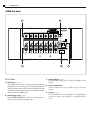
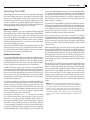
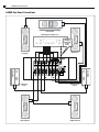
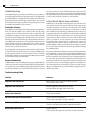
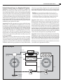
Instruction Manual
Model A-2000
Seven Channel Amplifier
2
Warnings
A-2000 7 Channel Amplifier
Please Read First
CAUTION: To reduce the risk of electric shock, do not remove the cover. No user
serviceable parts inside. Refer to qualified personnel.
WARNING: To reduce the risk of fire or electric shock, do not expose this appliance
to rain or moisture.
The lightning flash with arrowhead, within an equilateral triangle, is intended to alert the user to the presence of uninsulated “dangerous voltage”
within the product’s enclosure that may be of sufficient magnitude to
constitute a risk of electrical shock to persons.
The exclamation point within an equilateral triangle is intended to alert
the user to the presence of important operating maintenance (servicing)
instructions in the literature accompanying the appliance.
Precautions
Verify The Line Voltage
Your new amplifier has been factory configured for 120 or 230 (+/- 3%) volt AC lines
depending on what country you purchased it in. Connecting the amplifier to a line voltage other than that for which it is intended can create a safety and fire hazard, and may
damage the amplifier. If you have any questions about the voltage requirements for your
specific model, or about the line voltage in your area, contact Atlantic Technology before
plugging the unit into a wall outlet.
Verify AC Circuit Capacity
The high power output of your amplifier may require heavy power draw under full load
conditions. To insure proper performance, and to avoid potential safety hazards, we
recommend that it be connected to a minimum 20 Amp capacity circuit. Connecting
multiple amplifiers to the same circuit, or connecting it to a circuit used by other heavyuse power devices, such as air conditioners, may cause circuit breakers to trip.
NOTE: It is always a good idea to avoid using any audio or video equipment on the same AC
circuit as equipment with motors, such as air conditioners or refrigerators. This will lessen the
possibility of power variation and electrical start-up noise affecting your sound system.
Extension Cords and Power Strips
We do not recommend that extension cords be used with this product unless they are
of sufficient gauge to pass the necessary current during full load conditions. Most inexpensive extension cords are not capable of such high-current loads.
Similarly, should you use a power strip, surge protector or any type of AC power line
conditioning equipment, make certain that it is also able to handle the high current
loads this product will draw.
Handle the AC Power Cord Gently
When disconnecting the power cord from an AC outlet, always pull the plug, never pull
the cord. If you do not intend to use the amplifier for any considerable length of time,
disconnect the plug from the AC outlet. If the power cord is replaced, make certain that
it is of similar gauge. As with all electrical devices, do not run power cords under rugs
or carpets or place heavy objects on them. Damaged power cords should be replaced
immediately with cords meeting factory specifications.
Wiring
Cables that are run inside of walls should have the appropriate markings to indicate
compliance with, and listing by the UL, CSA or other standards required by the UL, CSA,
NEC or your local building code . Questions about cables inside of walls should be referred
to a qualified customer installer, or a licensed electrician or low-voltage contractor.
Installation Location
To assure proper operation and to avoid the potential for safety hazards, place the unit
on a firm and level surface capable of supporting 100 pounds or more. When placing the
amplifier on a shelf, be certain that the shelf and any mounting hardware can support the
weight of the amplifier and any additional items in the equipment rack, or on the shelf.
When positioning the amplifier in its final location, make certain that it has adequate
ventilation on all sides, as well as on the top and bottom. In particular, it is a good idea to
provide at least two or three inches of room above the amplifier for air circulation.
DO NOT place CDs, DVDs, videotapes, owner’s manuals, or other paper on top of, or
beneath, the unit, or in-between multiple amplifiers in a stack. This will block airflow,
causing heat build-up, degraded performance, and may create a possible fire hazard.
If the unit is to be enclosed in a cabinet or rack, make certain there is adequate air circulation. Sufficient ventilation should be provided so that hot air may exit, and cool air
may enter the cabinet. In some instances, a small cooling fan may be required to insure
adequate airflow through the cabinet. If you are in doubt as to the ventilation requirements for your specific installation, please contact us. Also, do not place the amplifier
directly on a carpeted surface, as this will inhibit airflow underneath as well as create a
potential fire hazard.
Avoid installation in humid locations, in extremely hot or cold locations, or in areas that
are exposed to direct sunlight or space heating equipment.
Loudspeaker Ratings
The Atlantic A-2000 has adequate power to drive most loudspeakers without producing
audible distortion. Most modern speakers are rated at four to eight ohms nominal impedance, but within some frequency ranges, the impedance may drop to two ohms. The
A-2000 is designed with substantial power reserves to protect you from experiencing any
problems at these low impedances, unless you demand excessively high volume levels.
Due to the high power output capability of the A-2000, it is important that the amplifier
not be used with speakers that aren’t capable of handling the A-2000’s power output or
in a manner that could lead to speaker damage. Before using the A-2000 for the first
time, make certain that your speakers are capable of handling its rated power output, at
the impedance rating of your speakers and that you read and understand the following
important note.
IMPORTANT NOTE Given the right set of circumstances any amplifier is capable of
damaging any loudspeaker, no matter what their respective power ratings. Damage can be
done either through excessive power output to the speaker or excessive distortion from the
amplifier due to clipping. Amplifier clipping is the result of asking the amplifier to deliver
substantially more power than it is capable of producing without excessive distortion. This
is the single most common cause of speaker damage and can happen no matter how high
the power rating of the attached speakers or amplifier may be. Atlantic Technology is not
responsible for damage to any speaker system or other component that is caused by using
products whose power rating is lower than that of the amplifier or in a manner that results
in amplifier clipping and therefore component damage.
Do Not Open The Cabinet
There are no user serviceable components inside this product. Opening the cabinet may
present a shock hazard, and any modification to the product will void your warranty. If
water or any metal object, such as a paper clip, coin or a staple, accidentally falls inside the
unit, disconnect it from the AC power source immediately, and contact Atlantic Technology
or your Dealer/Installer for further instructions.
IMPORTANT SAFETY NOTE
Before connecting a new component such as power amplifier to your audio or home
theater system it is always good practice to make certain that all components are turned
off, and preferably unplugged from their AC power source. Many modern electronics
products feature automatic turn-on circuits that may be activated during an installation,
causing the potential for damage to electronic components and/or speakers. Such damage is not covered by product warranties and Atlantic Technology specifically disclaims
responsibility for any such damage.
Model A-2000 Power Amplifier
3
Instruction Manual
Table of Contents
2
3
3
4
5
5
5
7
7
7
7
Please Read First
Features
Unpacking
Rear Panel
Connecting The A-2000
In order to receive the maximum enjoyment from your new amplifier, please
take a few minutes to read this manual. It will help you make certain that the
amplifier is properly configured for operation with the rest of the equipment
in your system.This brief investment of time will provide major dividends by
making certain that your amplifier is properly installed and optimized for the
specifics of your installation.If you have any questions about this product, its
installation or operation,please contact your Authorized Atlantic Technology
Dealer/Installer or us via e-mail at [email protected]
or via telephone at 781-762-6300.
Manual On
Output Settings
Features
7 Care and Maintenance
7
7
Cleaning
When You Are Away
8 Troubleshooting
8
8
8
Protection Circuitry
Service Information
Troubleshooting Guide
8 A Few Words About Hum and Noise
9
Thank you for buying this Atlantic Technology product. This unit has been
carefully designed to deliver the best possible sonic performance and
extended reliability. We trust that your new amplifier will bring many years
of listening pleasure to your multi-channel music or home theater system.
Input Connections
Speaker Connections
Power Control Connections
Remote Turn-On Using Products Equipped With a
Low Voltage Trigger Jack
Remote Turn on Using External AC to DC
Power Converter
Power Connection
7 Amplifier Operation
7
7
Model A-2000 Power Amplifier
Potential Ground Loops in a Complex A/V System
10 Specifications
Your new Atlantic Technology Multi-Channel Amplifier is a state of the art,high
performance audio device. It is built utilizing totally complementary circuitry
from input to output. The high current power supplies are driven by customdesigned toroid transformers which reduce hum and noise significantly.
Each of the seven amplifier modules incorporates 2 very high quality discrete output devices capable of passing in excess of 20 amps of current. The
amplifier’s circuitry is both very sophisticated in concept yet simple in layout
and construction.A minimum number of components are used in the signal
path to ensure excellent sound quality and reliability.These components have
been chosen for their ability to amplify the signal while adding or subtracting
nothing to/from the sound.
The advanced protection circuits (over-current, over-temperature, DC
offset)are external to the signal path and therefore don’t degrade the amplified signal in any way. No current or voltage limiting are employed to further
ensure signal purity and guarantee substantial dynamic range.Heat management is provided by custom-designed cast aluminum heat sinks that also
form the sides of the amplifier itself. The heat sinks have been “overspeced”
to ensure cool running and long life for the internal components, as heat is
the prime enemy of electronic parts.
For Future Reference
Unpacking
Record your A-2000’s serial number and date of purchase here. The serial number is
found on the back panel.
The carton and packing materials used in shipping your new amplifier were
specially designed to cushion it from the shocks and vibration of shipping.We
strongly suggest that you save the carton and packing materials to use if you
move, or if the unit ever needs to be shipped for any reason. To minimize the
size of the carton in storage, you may wish to flatten it by carefully opening
the top and bottom flaps and folding the carton flat. Other cardboard inserts
may be stored in the same manner.Packing materials that cannot be collapsed
should be saved along with the carton in a plastic bag.
Your new amplifier has been engineered using heavy duty materials for high
reliability and weighs a considerable amount (67 pounds). This substantial
weight requires that you pay special attention to unpacking and installation
of the unit. You may wish to have someone help you remove the unit from
its carton and place it in your chosen location.
Serial Number
Date of Purchase
The contents of this manual are Copyright © 2002 by Atlantic Technology International,
Corp., and may not be duplicated or reproduced by any means, whether physical, electronic
or otherwise without prior written consent from Atlantic Technology International, Corp.
Atlantic Technology and the Atlantic Technology logo are registered trademarks of Atlantic
Technology International, Corp.
Specifications are those in effect at the time of printing.Atlantic Technology International,
Corp. reserves the right to change specifications or designs at any time without notice
without obligation to modify existing units.
4
A-2000 Rear Panel
A-2000 7 Channel Amplifier
A-2000 Rear Panel
A
B
�������
���� �� �������� �����
�� ��� ����
���� ������ �� ���� ������������� ��� ������
��
��
��
��
�
�
������ ����� ������� ���������
�
�� �������
�����
������
�
�
����
�
�
����
����
�� ����������
����� ����������� �����
������ ���
���� �� ��������
C
Rear Panel
A Audio Inputs (see page 5)
Use the INPUT jacks to connect to the outputs of a surround processor,
preamplifier, AV receiver with preout connections, DVD player with
discrete five channel outputs, or HDTV product with built-in surround
decoder.Whatever kind of unit you connect be sure that it has a built-in
volume control as the A-2000 does not.
B Remote Trigger Input (see page 7)
Use the REMOTE TRIGGER jack to connect to a compatible processor
or other product with a 3-32 VDC trigger output.
D
E
C Speaker Outputs (see page 5)
Use the OUTPUT binding posts to connect the amplifier to your
speakers.
D Product Serial Number
Write this number in the space provided on page 3 for future
reference.
E AC Input (see page 7)
Use the included power cord (or a comparable cord of equal or greater
wire gauge)to connect your amplifier to a compatible AC power
source.
Connecting the A-2000
5
Instruction Manual
Connecting The A-2000
When making connections between any source components and the amplifier, or when making connections to any speaker, be certain that both the
input device(s) and the amplifier are turned off to assure that there will be
no unwanted signal transients that can damage the equipment or speakers.
As a rule, it is always best to unplug all equipment before making any connections, as many electronic products have a standby mode that may be
activated although the product may appear to be turned off.
Input Connections
Connecting the amplifier to your source equipment is simple. Using high
quality audio interconnect (“RCA”)cables,match the output channel designations on the rear of your processor (or other source equipment) to the input
jacks on the rear panel of your amplifier that have the same channel name
(see page 4). When making these connections, make certain to gently, but
firmly insert the plug into the jack.Loose connections can cause intermittent
sound and may damage your speakers.
The outer ring of the barrel assembly of some RCA plugs may be very tight,
and it is important to assure a proper connection between the interconnection cable and the input jack. Gently twisting the connector as you insert it
can often ensure good connections and full insertion.
Speaker Connections
To assure that the high quality signals produced by your amplifier are carried
to your speakers without loss of clarity or resolution,we recommend that you
use high quality speaker wire. Many brands of wire are available; the choice
may be influenced by the distance between your speakers and the amplifier,
the type of speakers you use, personal preferences, or other factors.
Regardless of the brand or type of speaker wire selected,we recommend that
you use a wire constructed of fine, multi-strand copper with a gauge of 14 or
heavier. Remember that in specifying wire, the lower the gauge number, the
heavier the cable will be.Wire with a gauge of 16 may be used for short runs
of less than ten feet. We do not recommend that you use any wires with an
AWG equivalent of 18 gauge or lighter,due to the power loss and degradation
in performance that may occur.
To connect the amplifier to your speakers a pair of multi-way binding posts
is provided for each channel output. These posts will accept bare or tinned
wire, pin connectors, spade lugs or “banana” type plugs, when they are permitted by local safety agencies. If bare wire is used for the connections, strip
approximately 1/2 to 3/4 inch (20mm) of insulation from the end of each
wire and carefully twist the strands of each conductor together. Be careful
not to cut the individual strands or twist them off.
Correct polarity connections (+ to +, - to -) are important to maintain
proper speaker phasing. When speaker phasing is correct, all speakers
move in and out together, preserving the imaging and bass response of
the program material. Out-of-phase connections mean that some speaker
cones will be moving in, while others move out. This will cause indistinct
or confused imaging, and muddled and cloudy sounds and lack of bass
response. To avoid incorrect phasing or polarity, be certain to use cable that
has distinct markings, colors, stripes, wording, or grooves on each side of the
speaker cable. When making connections to the amp and speakers, adhere
to a consistent pattern of using one side of the wire to the red terminals and
the other side to the black terminals. When using cable with markings on
one side only, traditional convention is to consider the marked side of the
wire as the red, or positive (+) connection, and the non-marked side as the
black or negative (-) connection.
Loosen the knobs of the amplifier’s speaker output terminals, far enough so
that the pass through hole is revealed. Follow the proper connection instructions for your system (and as outlined above) with regard to which terminals
are used. Once the connections are made, twist the cap back so that the connection is secured, but do not over tighten or use tools, as this may break the
delicate wire strands and decrease system performance.
If you are using spade lugs, connect them to the speaker wire using the
manufacturer’s instructions then loosen the caps on the amplifier’s speaker
terminals.Place the lugs between the plastic cap and the back of the terminal.
Be sure to observe proper polarity, using the appropriate speaker hook-up
icons for your system’s configuration. Using your fingers, tighten to obtain
a positive contact.
When using banana plugs, connections may be made by simply inserting
the appropriate jack affixed to your speaker wire into the hole provided on
the rear of the colored screw caps on the binding posts. Before using banana
type jacks make certain that the plastic screw caps are firmly tightened down
by turning them in a clockwise direction until they are snug against the
chassis. This will insure that the maximum surface area of the plug is in
contact with the jack when it is inserted. Once again, be certain to observe
proper polarity.
Run the cables to the speaker locations. It is recommended that the length of
wire connecting any pair of speakers be similar. For example, make certain
that the wire length connecting the left and right front, or the left and right
rear (surround) speakers are similar in length,even though one speaker may
be physically closer to the amplifier than the other. Do not coil and/or wrap
the excess wire around itself, as such a coil makes an inductor that creates
frequency response variations in your system. Finally, connect the wires to
the speakers, again being certain to observe proper polarity. Remember to
connect your negative and positive wires to the matching terminal on the
speaker.
NOTE: While most speaker manufacturers adhere to an industry
convention of using red terminals for positive connections and black
terminals for negative, some manufacturers may vary from this configuration. To assure proper phase connections, and optimal performance, consult the identification plate on your speaker terminals, or
the speaker’s manual to verify polarity. If you do not know the polarity
of your speaker, consult the speaker’s manufacturer for further information.
6
A-2000 Rear Panel Connections
A-2000 7 Channel Amplifier
A-2000 Rear Panel Connections
�
�
�
�
������ �������
������������� ����������������
������� ��
��� �������
���� �������
�� �����
������
�
�
����� �������
���� �������
�������
���� �� �������� �����
�� ��� ����
���� ������ �� ���� ������������� ��� ������
��
��
��
��
�
�
������ ����� ������� ���������
�
�� �������
�����
������
�
�
�
�
�
�
����
����
����
�� ����������
����� ����������� �����
������ ���
���� �� ��������
�
�
�
�
���� ���� �������
����� ���� �������
�
����� ��������
�������
�
���� ��������
�������
�
�
Amplifier Operation
7
Instruction Manual
Power Control Connections
Amplifier Operation
The Model A-2000 features a built-in remote turn-on system that will automatically switch the amplifier on when a connected device in the system is
switched on.
After all connections have been made you are ready for listening. First, with
the processor’s volume control all the way down, turn on the source components and processor in your system. It is always a good idea to turn on your
amplifier LAST. This avoids the possibility of any turn on pops or transients
from other equipment being amplified and sent to your speakers where they
may cause damage. Be sure to always start with a low volume level on your
controller or preamp to avoid damage to your speakers.
Remote Turn-On Using Products Equipped With a Low
Voltage Trigger Jack
Press the front panel power switch on the amplifier so that it is in the ON
position. Then, using an accessory cable with a 3.5mm mono mini-plug on
each end, connect the trigger-output jack on the rear of the source device to
the trigger input jack on the back panel of the amplifier. When these connections are made, the amplifier will automatically turn on whenever the
triggering device is turned on.
Remote Turn on Using External AC to DC Power Converter
If your processor or receiver does not have a dedicated trigger jack, it is still
possible to activate the unit for automatic turn on when a Switched Outlet
is available on the rear of the source device. To control the amplifier in this
fashion you will need a small AC to DC power converter, capable of delivering a 6 to 12 volt DC signal. The DC voltage should terminate in a standard
3.5mm type mini plug. This type of converter may be obtained as a Power
Adapter from many electronics retailers, or may be obtained at Radio Shack
stores as catalog number 273-1758.
When installing, plug the AC adapter into a switched outlet that will be activated when you wish to have the amplifier turn on.This may be the switched
outlet at the rear of an AC receiver or other audio equipment. Connect the
3.5mm mini-plug from the adapter to the trigger-input jack on the back
panel of the amplifier. Press the Main Power Switch on the front panel of the
amplifier in so that it is in the ON position. The amplifier will now turn on
and off automatically, based on the status of the controlling device.
Power Connection
Once all audio and system connections have been made, connect the supplied power cord (or an equivalent cord of equal or heavier gauge) to the
amplifier first, and then connect it to an AC power source. Please make
certain that the amplifier is turned off and that the device connected to the
remote trigger input is off when connecting the power cord and plugging
it into an AC outlet.
CAUTION: Do not plug the amplifier directly into the “Switched
Accessory” outlet of another device! These outlets are intended for
use with low current draw products, such as tuners, CD players or
cassette decks. These outlets cannot safely supply the high current
required by a power amplifier like the A-2000. Using switched outlets
like these for a power amplifier poses a significant safety hazard.
IMPORTANT NOTE: It is also not recommended that you connect
other power amplifiers or products with a high current draw, to the
same AC power circuit as the amplifier, unless they are used with the
remote power turn on and some sort of power on sequencing system.
The simultaneous turn-on of multiple amplifiers on the same circuit
may cause circuit breakers to trip, due to the high current draw.
Manual On
Simply press in the front panel power switch until the light is illuminated.
There will be a short pause from the time the power is turned on until power
is applied to the speakers. This is intentional, and protects your speakers
from damage while the amplifier stabilizes. You may also hear a relay click
during start up. This is also normal. To turn the unit off, switch the power
switch to the off position.
Output Settings
All volume and level adjustments are made at your preamp, controller or
surround processor. To assure proper sound field imaging, you should re-set
the output levels of the channels on your processor when using the amplifier
for the first time. The circuitry in your new amplifier may be different from
your previous one, and checking the output levels will make certain that the
processor, amplifier and speakers are properly matched.
Care and Maintenance
Cleaning
If the unit becomes dirty, wipe it with a clean, soft, dry cloth. If necessary,
first wipe the surface with a soft cloth slightly dampened with mild soapy
water, then with a fresh cloth slightly dampened with clean water. Wipe dry
immediately with a dry cloth. NEVER use benzene, thinner, alcohol or any
other volatile cleaning agent. Do not use abrasive cleaners, as they may damage the finish of the metal parts.Avoid spraying insecticide, waxes, polishing
agents, or any aerosol product near the unit.
When You Are Away
If you will not be using your home theater system for an extended period
of time, it is always a good idea to disconnect all associated units from the
AC wall current.
8
Troubleshooting
A-2000 7 Channel Amplifier
Troubleshooting
Your A-2000 is designed to provide years of trouble free operation. However,
as with any sophisticated electronic device,there may be occasional problems
upon initial installation,or during the life of the unit.The items on this list are
a brief guide to the minor problems that you may be able to correct yourself.
If these solutions do not rectify a problem, or if the problem persists, contact
your Atlantic dealer/installer or us for assistance.
Protection Circuitry
Your amplifier uses advanced protection circuitry that does not require fuses.
In the event that the amplifier senses a shorted speaker wire, DC voltage
on an input connection or thermal overload creates a condition that could
potentially cause damage to the unit or to your speakers,it will automatically
shut down. If this should happen, first check all speaker wire connections,
both at the speakers themselves and at the speaker terminals on the back of
the A-2000 to make certain that none of the strands from any channel touch
another channel, and that none of the strands from a "positive" terminal
touch those from a "negative" terminal. Even a few stray wire strands can
cause the unit to go into protection mode.
After checking all speaker connections, turn the unit back on. If it continues
to turn off, disconnect the speakers one by one and try the amplifier again,
after disconnecting each one, to see if one speaker (or wire) is causing the
problem. If all potential sources of trouble check out OK, contact your dealer
or us for further assistance and information.
Service Information
A-2000 contains no user serviceable parts.If you suspect a problem that may
require service assistance, contact your Atlantic Technology dealer/installer
or us or by phone at 781-762-6300.It is important that any repairs be carried
out only by an authorized service agent. This will assure proper service and
preserve the protection of your Limited Warranty/Free Extended Service
Agreement. Keep your sales slip or receipt in a safe place with this manual as
well as your Extended Service Agreement certificate so that it will be available
to verify coverage, should you experience a covered problem.
A Few Words About Hum and Noise
Audible hum, or a discernable low frequency noise, is one of the most common problems in audio/video systems. This hum, which may be present
even when the volume is at a low level or when the power is off, is usually
caused by a situation known as a ground loop . A ground loop occurs when
there is a difference in ground voltage potential between two or more pieces
of equipment in the system. For example, there could be an electrical ground
for the main electrical service that is connected to a cold water pipe in the
basement and a ground rod driven into the earth outside the house for the
cable TV system. If two or more components are connected electrically
(through RCA cables, antenna leads, etc.) and they are also connected to
both ground systems (the house AC plugs and the cable TV system in our
example) multiple potential ground current paths exist. This can and often
does cause low-level noise, hum, and an increased possibility for damage
due to lightning strikes.
The growing sophistication of home theater systems,and the increased number of components used to create these systems has dramatically increased
the potential for the possibility of ground loops.While it is natural to suspect
that the components in your system are the cause of the hum, in many cases
the cause may be due to these other conditions. In particular, cable TV connections from outside the house (as noted above) have become a major source
of hum. In most cases, one of the following suggestions should help you to
solve a hum problem in your system. Please try these steps in the sequence
shown, proceeding from one step to the next if the prior suggestion does not
eliminate the problem.
Troubleshooting Guide
Problem
Solutions
Amplifier will not turn on
Master Power Switch turned off (No power light LED)
Turn on Master Power Switch
Amplifier will not turn on
Remote trigger cable not properly connected
Verify connection of trigger cable at both ends
Amplifier turns on, but no audio from
one or more channels
Input plugs not connected to proper jack or are loose
Check input connections
No audio from one or more channels
Speakers not connected properly
Check speaker connections at amp and speaker
Audio levels differ
Improper settings or output levels from the processor or controller
Check the settings on your preamp, processor or controller
Audio plays, then cuts off
Amplifier shorted
Check speaker connections for short circuit at amp and speaker
A Few Words About Hum and Noise
9
Instruction Manual
Potential Ground Loops in a Complex A/V System
Suggestion 1 To determine if a cable TV connection is responsible for the
hum, first turn all components off. Disconnect the cable TV feed to your
system at the first place where it connects to your components.Alternatively,
disconnect the cable TV wire (not the AC wire to the cable box, but the cable
antenna wire) where it is connected at the wall outlet.Turn your system back
on, and listen if the hum has disappeared. If removing the cable TV feed has
eliminated the hum, you will need to insert a Ground Loop Isolator before
reconnecting the cable TV feed, or contact your cable TV operator to see
if they can better isolate your cable feed. Ground Loop Isolators should be
available from your local Audio Video dealer.
Suggestion 2 Turn off all components in your system, and then disconnect
the input cables at the amplifier. Turn the amplifier back on, and see if the
hum is still present.If the hum disappears,the fault may be in the input cables
used. Try replacing them with cables that have better shielding, and make
certain that the input cables are not running on top of or directly adjacent
to and parallel with any AC power cords. Change the cables one at a time to
determine if one, or all cables is responsible. If the hum disappears when
the input cables are disconnected, but returns after the cables are changed
and the system re-connected, the problem may be caused by your processor,
receiver or preamplifier.
Suggestion 3 Ground loop problems may also be caused by poor grounding
of the electrical system in your home, particularly when there are multiple
components with three prong grounded power cords. Try unplugging these
components one at a time,and see if one or all of them is causing the problem.
The ultimate solution to this type of problem is to re-wire your house with an
isolated, star type grounding configuration.We recognize, however, that this
may be impractical and expensive. In some cases, the use of an approved AC
Power Isolation Transformer of sufficient capacity may solve this problem.
Warning: If you suspect that the grounding system in your home’s
electrical wiring is causing the hum problem, it is important that you do
not make any changes to the wiring yourself. Only a licensed electrician
should make any changes to household wiring, and they must be made
in full compliance with all local building, safety and electrical codes.
Suggestion 4 Hum may also be caused by faulty earth grounds in your
home’s electrical system. In the past, cold water pipes were often used for
the earth ground, so it is important to make sure that your ground connection is still valid and has not become loose or corroded. The cold water pipe
method may no longer be valid in some locations due to requirements that
the water meter be isolated from the water mains with a length of PVC pipe,
thus interrupting the ground circuit. The safest, and most reliable, approach
may be to provide your own ground. This can be accomplished by having a
licensed electrician drive at least five feet of copper-jacketed steel grounding
rod into the earth, and using that for your grounding connection.
Suggestion 5 If you have hum in your video display device (bars that roll up
through image at 12-14 second intervals),this may be related to hum you also
experience in your audio system.The previous suggestion tips may help with
this also. If not, try isolating the ground in the projectors video signal cable
with a base-band video isolation transformer, such as the Jensen VB-1BB.
If the hum persists after all of the above suggestions have been tried, contact
our customer service department for assistance.
Ground Loop Diagram
Coax Cable
Cable Feed
A/V Cables
60Hz AC
Ground
60Hz AC
Ground
AC Line
AC Ground
Main House
Grounding
AC Line
10
Specifications
A-2000 7 Channel Amplifier
Specifications
Power Output
7 x 120 watts @ 8 ohms, 20 - 20kHz, 0.08% THD
Frequency Response
20Hz. -20kHz. +/- 0.3 dB at rated output
Total Harmonic Distortion (THD) Less than 0.08% at all frequencies,
less than 0.008% at 1 kHz
Power Bandwidth
10Hz - 100 kHz +0/-3 dB
Crosstalk
Greater than -90 dB from 20 Hz to 20Khz
Voltage Gain
29dB
Input Impedance
27k ohms
Input Sensitivity
1.2 Volts for Full Rated Output
Remote Trigger Voltage
3 - 18 Volts AC/DC
Dimensions (HxWxD)
7.75” x 17.2” x 18”
Weight
67.25 lbs net, 76 lbs gross
Power Requirements
115VAC, +/- 3%, 50Hz - 60 Hz. 1800 watts, maximum
Version 1.4
010-0200