1
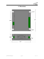
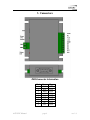
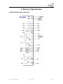
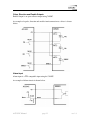
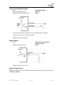
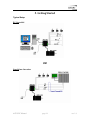
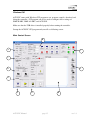
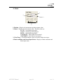
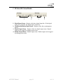
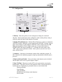
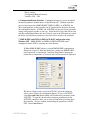
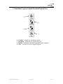
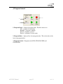
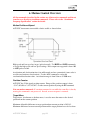
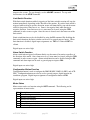
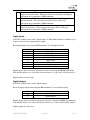
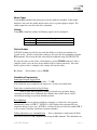
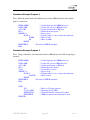
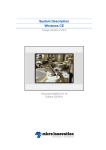
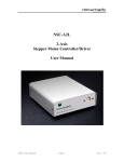
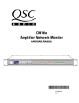
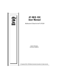
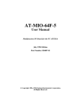
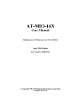
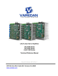
ACE-SXC
Single Axis Step Motor Controller
with
USB 2.0 Communication
ACE-SXC Manual
page 1
rev 1.8
COPYRIGHT © 2007 ARCUS, ALL RIGHTS RESERVED
First edition, Oct 2007
ARCUS TECHNOLOGY copyrights this document. You may not reproduce or translate
into any language in any form and means any part of this publication without the written
permission from ARCUS.
ARCUS makes no representations or warranties regarding the content of this document.
We reserve the right to revise this document any time without notice and obligation.
Revision History:
1.01 – First revision
1.02 – Added dimensions
1.03 – Added ASCII command set
1.3 – Added new graphics
1.4 – Added firmware and software compatibility
1.5 – New hardware, outputs changed, removed loopwhile/repeat
1.6 – Delay resolution updated
1.7 – Updated introduction, updated alarm input schematic, added connector
information, moved GUI section up to section 5, added active/low high for
inputs and outputs, updated GUI section, updated stand-alone command
spec, updated ASCII command spec
1.8 – Removed differential output spec, added pull-down resistor to circuit
overview, updated B/C/D/F/J sections of GUI, already in motion
situations, enable as GPIO, updated cable accessory names (male side)
Firmware Compatibility:
V410
Software Compatibility:
V413
ACE-SXC Manual
page 2
rev 1.8
Table of Contents
1. Introduction..................................................................................................................... 6
2. Dimensions ..................................................................................................................... 7
3. Connectors ...................................................................................................................... 8
DB9 Connector Information ........................................................................................... 8
2 pin Connector Information........................................................................................... 9
10 pin Connector Information......................................................................................... 9
4. Electrical Specifications................................................................................................ 10
Internal Interface Circuit Overview .............................................................................. 10
Power Input................................................................................................................... 11
Communication:............................................................................................................ 11
Pulse, Direction and Enable Outputs ............................................................................ 12
Alarm Input................................................................................................................... 12
Limits, Home and Digital Inputs: ................................................................................. 13
Digital Outputs:............................................................................................................. 13
Operating Temperature ................................................................................................. 13
5. Getting Started .............................................................................................................. 14
Typical Setup ................................................................................................................ 14
Windows GUI ............................................................................................................... 15
Main Control Screen ..................................................................................................... 15
A. Status.................................................................................................................... 16
B. Axis Control ......................................................................................................... 17
C. DI Status/DO Status/Enable ................................................................................. 18
D. Configuration ....................................................................................................... 19
E. Terminal ............................................................................................................... 22
F. Variable Status...................................................................................................... 22
G. Standalone Program File Management ................................................................ 23
6. Motion Control Overview............................................................................................. 26
Motion Profile and Speed ............................................................................................. 26
Position Counter............................................................................................................ 26
Target Move.................................................................................................................. 26
Home Move .................................................................................................................. 27
Jog Move....................................................................................................................... 27
Stopping Motor ............................................................................................................. 27
Limit Switch Function .................................................................................................. 28
Alarm Switch Function ................................................................................................. 28
Configuration Button Function ..................................................................................... 28
Motor Status.................................................................................................................. 28
Digital Inputs ................................................................................................................ 29
Digital Outputs.............................................................................................................. 29
Motor Power ................................................................................................................. 30
Device Number ............................................................................................................. 30
Standalone Programming.............................................................................................. 30
Storing to Flash ............................................................................................................. 31
ACE-SXC Manual
page 3
rev 1.8
7. Connecting to DMX-K-DRV, DMX-A2-DRV, and ACE-SDX .................................. 32
Connecting ACE-SXC to DMX-K-DRV-11/17 ........................................................... 32
Connecting ACE-SXC to DMX-K-DRV-23 ................................................................ 32
Connecting ACE-SXC to DMX-A2-DRV-17/23 ......................................................... 33
Connecting ACE-SXC to ACE-SDX............................................................................ 33
8. DriveMax Configuration............................................................................................... 34
Configuration Method #1 – Using Windows PC.......................................................... 35
Configuration Method #2 – Using the Configuration Button....................................... 35
9. Communication – USB ................................................................................................. 36
USB Communication API Functions............................................................................ 36
USB Communication Issues ......................................................................................... 37
10. ASCII Language Specification ................................................................................... 38
11. Standalone Language Specification............................................................................ 41
; ..................................................................................................................................... 41
ABORTX ...................................................................................................................... 41
ABS............................................................................................................................... 42
ACC .............................................................................................................................. 42
DELAY ......................................................................................................................... 43
DI .................................................................................................................................. 43
DI[1-8] .......................................................................................................................... 44
DO................................................................................................................................. 44
DO[1-2]......................................................................................................................... 45
ECLEARX .................................................................................................................... 46
ELSE ............................................................................................................................. 46
ELSEIF ......................................................................................................................... 47
END .............................................................................................................................. 48
ENDIF........................................................................................................................... 48
ENDSUB....................................................................................................................... 49
ENDWHILE ................................................................................................................. 49
EO ................................................................................................................................. 50
GOSUB ......................................................................................................................... 50
HOMEX[+ or -] ............................................................................................................ 51
HSPD ............................................................................................................................ 51
IF ................................................................................................................................... 52
INC................................................................................................................................ 53
JOGX[+ or -]................................................................................................................. 53
LSPD............................................................................................................................. 54
MSTX ........................................................................................................................... 54
PX ................................................................................................................................. 55
STOPX.......................................................................................................................... 55
STORE.......................................................................................................................... 56
SUB............................................................................................................................... 56
V[1-50].......................................................................................................................... 57
WAITX ......................................................................................................................... 58
WHILE.......................................................................................................................... 59
X.................................................................................................................................... 60
ACE-SXC Manual
page 4
rev 1.8
Standalone Example Program 1.................................................................................... 61
Standalone Example Program 2.................................................................................... 61
Standalone Example Program 3.................................................................................... 61
Standalone Example Program 4.................................................................................... 62
Standalone Example Program 5.................................................................................... 62
Standalone Example Program 6.................................................................................... 63
ACE-SXC Manual
page 5
rev 1.8
1. Introduction
ACE-SXC is a single axis step motor controller with following features:
-
USB 2.0 Communication
PC based control through USB 2.0
Standalone Control with BASIC-like programming language
12-48VDC voltage input
Pulse/Dir open-collector signal output
400K maximum pulse rate output
Open-collector Enable output
TTL Alarm input
Opto-isolated +Limit, -Limit, and Home inputs
Three Opto-isolated Digital inputs
Two Opto-isolated Digital outputs
DMX-K-DRV, DMX-A2-DRV and ACE-SDX driver configuration
ACE-SXC Manual
page 6
rev 1.8
2. Dimensions
ACE-SXC Manual
page 7
rev 1.8
3. Connectors
DB9 Connector Information
Pin#
1
2
3
4
5
6
7
8
9
ACE-SXC Manual
Name
PWR
PUL
ENA
ALM
5V+
GND
DIR
NC
5V+
page 8
Type
OUT
OUT
OUT
IN
OUT
OUT
OUT
OUT
OUT
rev 1.8
2 pin Connector Information
Pin #
1
2
Name
G
V+
Description
Ground
Power Input +12 to +48VDC
Mating Connector Description:
Mating Connector Manufacturer:
Mating Connector Manufacturer Part:
2 pin 0.2” (5.08mm) connector
On-Shore
EDZ950/2
Note: Other 5.08mm compatible connector can be used.
10 pin Connector Information
Pin #
1
2
3
4
5
6
7
8
9
10
Name
DO2
DO1
DI3
DI2
DI1
HOME
-LIM
+LIM
NC
OPTO-IN
Description
Digital Output 1
Digital Output 2
Digital Input 3
Digital Input 2
Digital Input 1
Home Input 1
Minus Limit Input
Plus Limit input
No Connection
Opto-supply in (12-24VDC)
Mating Connector Description:
Mating Connector Manufacturer:
Mating Connector Manufacturer Part:
10 pin 0.15” (3.81mm) connector
On-Shore
EDZ1550/10
Note: Other 3.81mm compatible connector can be used.
ACE-SXC Manual
page 9
rev 1.8
4. Electrical Specifications
Internal Interface Circuit Overview
ACE-SXC Manual
page 10
rev 1.8
Power Input
Regulated Supply Voltage Range:
Recommended Current for power supply:
+12 to 48 VDC
200 mA
(Current required for powering the
ACE-SXC. If driver is powered
through the DB-9, additional current
is required to power the driver.)
Power and ground signals that are supplied to ACE-SXC through the 2 pin
connector are also available through the DB9 pin connector.
Important Note: If the driver is powered through the DB9 connector, make sure that
the voltage of the power supply does not go over the maximum rated power supply
voltage of the driver. For example, DMX-K-DRV maximum allowed voltage is
+24VDC. If ACE-SXC is powered by +48VDC, powering the DMX-K-DRV through
the DB9 connector will damage the driver.
Communication:
Communication:
Connector:
ACE-SXC Manual
USB 2.0
Mini-B to A
page 11
rev 1.8
Pulse, Direction and Enable Outputs
Enable Output is an open collector output using 74LS07.
An example of a pulse, direction and enable circuit connection to a driver is shown
below.
Alarm Input
Alarm input is a TTL compatible input using the 74LS07.
An example of Alarm circuit is shown below.
ACE-SXC Manual
page 12
rev 1.8
Limits, Home and Digital Inputs:
Type:
Opto voltage supply input:
Maximum diode forward current:
Opto-isolated inputs
+24 VDC
50mA
4.7K resistor is built in to the limit, home and digital inputs to limit the
current across the diode of the opto-isolator.
Digital inputs are active high.
Digital Outputs:
Type:
Opto-isolated open-emitter
transistor output
50 mA
Maximum emitter current:
Digital outputs are active low.
Operating Temperature
Electronic components used in ACE-SXC have maximum ambient operating temperature
of 85 degree Celsius.
ACE-SXC Manual
page 13
rev 1.8
5. Getting Started
Typical Setup
PC-Controlled
OR
Stand-Alone Operation
ACE-SXC Manual
page 14
rev 1.8
Windows GUI
ACE-SXC comes with Windows GUI program to test, program, compile, download, and
debug the controller. GUI program can also be used to configure driver settings of
DMX-K-DRV, DMX-A2-DRV, and ACE-SDX.
Make sure that the USB driver is installed properly before running the controller.
Startup the ACE-SXC GUI program and you will see following screen:
Main Control Screen
B
A
J
C
D
I
E
F
ACE-SXC Manual
G
H
page 15
rev 1.8
A. Status
1
2
3
4
1. Position – Display of current motor position counter value
2. Status – Display of current motor status. Possible values are
ACCEL – acceleration in progress
CONST – constant speed in progress
DECEL – deceleration in progress
-LIM ERROR – minus limit error occurred
+LIM ERROR – plus limit error occurred
3. Clear Error – Clear Error button is used to clear the Limit error status.
4. Limit and Home and Alarm Input Status – Display of limits and home and
alarm input status.
ACE-SXC Manual
page 16
rev 1.8
B. Axis Control
3
4
5
6
9
10
1
2
11
12
7
8
1. Target Position/Speed/Accel
Target Position – use this to set the target position. This position is the
pulse position.
High/Low Speed – use this to set the speed of the move. This value is in
pulses/second.
Accel – acceleration value in milliseconds
2. Set Position – Set Position button
3. DATUM – Absolute move to zero position. Maximum delta from current
position to target is 262,143. If greater, then move will not perform.
4. ABS – Absolute move to target position. Maximum delta from current
position to target is 262,143. If greater, then the move will not perform.
5. JOG- - Jog to minus direction
6. JOG+ - Jog to plus direction
7. RSTOP – Stop with deceleration
8. ISTOP – Immediate stop without deceleration
9. HOME- - Homing in minus direction
10. HOME+ - Homing in plus direction
11. ABS Mode – Set to absolute move mode. In ABS mode, all position moves
go directly to the target position.
12. INC Mode – Set to incremental move mode. In INC mode, all moves
increment/decrement from the current position.
ACE-SXC Manual
page 17
rev 1.8
C. DI Status/DO Status/Enable
1
2
3
4
1. Digital Input Status – Display of the three digital input bits. If the digital
input pin is grounded, the digital input is turned on.
2. Configuration Button Input Status – Display of the driver configuration
button.
3. Digital Output Status – Display of the two digital output status. Digital
output can be toggled by clicking on the circle.
4. Enable Output Status – Enable output status. Enable output can be toggled
by clicking on the circle.
ACE-SXC Manual
page 18
rev 1.8
D. Configuration
1
2
3
6
5
4
7
1. Polarity – Direction polarity can be configured to change the rotational
direction. Limit switch input can be configured. Limit switch polarity setting is
valid only when the limit switch function is enabled.
2. Product ID and Firmware – Product ID and firmware is shown to confirm the
ACE-SXC product. Firmware version loaded on the ACE-SXC is shown. Device
name can be changed so that multiple ACE-SXC can be connected on the USB.
When entering the new Device Name, make sure to enter in the format of
SXCXX where XX ranges from 00 to 99. To change the device name, click
“SET”, then store the parameter to flash. After a power cycle, the new device
name will take effect.
3. Autostart – Autostart is for automatic startup of the standalone program. If
this is checked, the standalone program startup up automatically when the unit is
powered.
4. Limit and Alarm Disable – Limit and alarm switch function can be disabled
and the inputs can be used as general purpose inputs.
5. Store To Flash – Parameters on the ACE can be permanently stored on the
flash memory. The unit is powered, the parameter values stored on the flash is
loaded and used. Following are parameters that are stored on the flash.
- Direction Polarity
- Limit Polarity
- Autostart Enable
- Disable Limit and Alarm switch function
- Device Name
ACE-SXC Manual
page 19
rev 1.8
- Driver settings
- Configuration Button Selection
- Variables V26 – V50
6. Configuration Button Selection – Configuration button is used to download
the driver parameters without the use of the Windows PC. With the controller
powered and connected to DMX-K-DRV, DMX-A2-DRV, or ACE-SDX, the
driver configurations on the controller can be downloaded to the driver by using
the configuration button. A2-DRV and ACE-SDX use the same driver parameter
settings and grouped together as one type. Select the driver type that will be used
with the configuration button and once selected, store to the flash memory so that
the driver type and driver parameters to be used will be stored to the controller.
7. DMX-K-DRV and DMX-A2-DRV/ACE-SDX Configuration using
Windows GUI – DMX-K-DRV and DMX-A2-DRV/ACE-SDX can be
configured from the GUI by selecting one of the buttons.
1. When DMX-K-DRV button is selected DMX-K-DRV configuration
dialog box is opened. From this dialog box, settings for DMX-K-DRV
can be uploaded or downloaded. Note that Temperature (showing the
current driver temperature as detected) and Version can only be uploaded.
The driver settings can be stored on ACE-SXC so that the parameter
values can be used by the configuration button. To save to ACE-SXC,
select Save and Close button which will download the parameters to the
ACE-SXC. To store the downloaded parameters permanently on the
ACE-SXC controller, make sure to store to flash before powering down
the controller. To close without downloading the parameters to ACESXC, select Cancel button.
ACE-SXC Manual
page 20
rev 1.8
2. When DMX-A2-DRV/ACE-SDX button is selected DMX-A2DRV/ACE-SDX configuration dialog box is opened. From this dialog
box, settings for DMX-A2-DRV/ACE-SDX can be uploaded or
downloaded. Note that Temperature (showing the current driver
temperature as detected) and Version can only be uploaded.
The driver settings can be stored on ACE-SXC so that the parameter
values can be used by the configuration button. To save to ACE-SXC,
select Save and Close button which will download the parameters to the
ACE-SXC. To store the downloaded parameters permanently on the
ACE-SXC controller, make sure to store to flash before powering down
the controller. To close without downloading the parameters to ACESXC, select Cancel button.
ACE-SXC Manual
page 21
rev 1.8
E. Terminal
Interactive terminal commands can be sent and replies can be received.
See interactive commands for details of the interactive commands.
F. Variable Status
View the status of variables 1-50. Note that this window is read-only.
1
1. Command line – To write to variable, use V[1-50] = [value] syntax.
ACE-SXC Manual
page 22
rev 1.8
G. Standalone Program File Management
1
2
3
1. Open – Open standalone program
2. Save – Save standalone program
3. New – Clear the standalone program editor
H. Standalone Program Editor
ACE-SXC Manual
page 23
rev 1.8
I. Standalone Program Compile/Download/Upload/View
1
2
3
4
1.
2.
3.
4.
Compile – Compile the standalone program
Download – Download the compiled program
Upload – Upload the standalone program from the controller
View – View the low level compiled program
ACE-SXC Manual
page 24
rev 1.8
J. Program Control
3
1
2
1. Program Status – display of program status. Possible statuses are
Idle – program is not running
Running – program is running
Paused – program is paused
Errored – program is in error status
2. Program Index – display of low level program index. This is the index of the
low level program index.
3. Program Control – Program can be RUN, STOP, PAUSED, and
CONTINUED.
ACE-SXC Manual
page 25
rev 1.8
6. Motion Control Overview
All the commands described in this section are all interactive commands and do not
transfer over directly to standalone commands. Please refer to the “Standalone
Language Specification” section for details.
Motion Profile and Speed
ACE-SXC incorporates trapezoidal velocity profile as shown below.
High speed and low speed are in pps (pulses/second). Use HSPD and LSPD commands
to set/get the high speed and low speed settings. Pulse output rate supported is from 100
to 400K pulses/second.
Acceleration and deceleration time is in milliseconds and are symmetrical (same value is
used for acceleration as deceleration). Use the ACC command to set/get the
acceleration/deceleration value. Acceleration range is from 10 msec to 1000 msec.
Position Counter
ACE-SXC has 32 bit signed position counter. Range of the position counter is from
–2,147,483,648 to 2,147,483,647. Get the current position by using the PX command.
Note on motion commands: If a motion command is sent while the controller is already
moving, the command is not processed. Instead, an error response is returned.
Target Move
Target move, also known as absolute move, is used to move the motor to the desired
position from the current position.
Maximum allowable difference to target position from current position is 262,143.
Maximum difference between current position and the target position has to be less than
ACE-SXC Manual
page 26
rev 1.8
or equal to 262,143. For example, if the current position counter is 1000, target position
allowed will be between -261,143 (1,000-262,143) and 263,143 (1,000+262,143).
ACE-SXC can operate in either incremental or absolute move modes. Use X command
to make moves. Use the INC and ABS commands to set the move mode. Use the
MODE command to read the current move mode.
Home Move
Home search sequence involves moving the motor towards the home switch and then
stopping when the home input is detected. Use the H+/H- command. Following
sequence shows the homing routine.
A.
B.
Issuing home command starts the motor from low speed and
accelerates to high speed.
As soon as the home input is triggered, the position counter is reset to
zero and the motor stops immediately. If the home switch is triggered
in the middle of the acceleration, the motor stops immediately.
To trigger the home input switch, supply the opto-supply voltage with 24VDC and
connect the home input signal to opto-supply ground.
If home switch is not used, home input can also be used as general purpose input. Digital
input assignment for the home input switch is DI6.
Digital inputs are active high.
Jog Move
Jog move is used to continuously move the motor without stopping. Use J+/Jcommands.
Stopping Motor
When motor is moving, jogging, or homing, motion can be stopped abruptly or with
deceleration. It is recommended to use decelerate and stop command so that there is less
ACE-SXC Manual
page 27
rev 1.8
impact to the system. To stop abruptly, use the ABORT command. To stop with
deceleration, use the STOP command.
Limit Switch Function
With limit switch function enabled, triggering of the limit switch in motion will stop the
motion immediately depending on the direction of the motion. If positive limit switch is
triggered while moving in positive direction, motor will immediately stop and the motor
status bit for positive limit error is set. Same is for negative limit while moving in
negative direction. Once limit error is set, status must be cleared (using the CLR
command) in order to move again. Once the error is cleared, move the motor out of the
limit switch.
Limit switch function can also be disabled by using the DL command. By disabling the
limit switch function, the limits switches can be used as general purpose inputs. When
limit function is disabled, digital input assignments are: DI5 for –Limit and DI7 for
+Limit.
Digital inputs are active high.
Alarm Switch Function
Alarm switch when triggered will immediately stop the motor if in motion regardless of
the direction of the motor. Once alarm error is set, status must be cleared (using the CLR
command) in order to move again. Alarm switch function can be disabled using the DL
command and alarm input can be used as general purpose input as DI8.
Digital inputs are active high.
Configuration Button Function
Configuration button is used to configure the DMX-K-DRV, DMX-A2-DRV, and ACESDX. Configuration button can also be used as general purpose digital input in the
standalone program. Digital input assignment of configuration button is DI4.
Digital inputs are active high.
Motor Status
Motor status can be read anytime using the MST command. The following are bit
representation of motor status.
Bit
0
1
2
3
4
5
Description
Motor running at constant speed
Motor in acceleration
Motor in deceleration
Home input switch status
Minus limit input switch status
Plus limit input switch status
ACE-SXC Manual
page 28
rev 1.8
6
7
8
Minus limit error. This bit is latched when minus limit is hit during
negative direction motion. This error must be cleared before issuing any
subsequent move commands (CLR command).
Plus limit error. This bit is latched when plus limit is hit during positive
direction motion. This error must be cleared before issuing any
subsequent move commands (CLR command).
Alarm error. This bit is latched when the alarm input is triggered while
motion is in progress. This error must be cleared before issuing any
subsequent move commands (CLR command).
Digital Inputs
ACE-SXC module comes with 3 digital inputs. If limit/alarm function is disabled, up to
8 inputs can be used as general purpose inputs
Read digital input status using the DI command. See description below:
Bit
0
1
2
3
4
5
6
7
Description
Digital Input 1
Digital Input 2
Digital Input 3
Configuration Button
Minus Limit
Home
Plus Limit
Alarm
Digital input values can also be referenced one bit at a time by the DI[1-8] commands.
Note that the indexes are 1-based for the bit references (i.e. DI1 refers to bit 0, not bit 1)
Digital inputs are active high.
Digital Outputs
ACE-SXC module comes with 2 digital outputs.
Read/set digital output status using the DO command. See description below:
Bit
0
1
Description
Digital Output 1
Digital Output 2
Digital output values can also be referenced one bit at a time by the DO[1-2] commands.
Note that the indexes are 1-based for the bit references (i.e. DO1 refers to bit 0, not bit 1)
Digital outputs are active low.
ACE-SXC Manual
page 29
rev 1.8
Motor Power
Using the EO command, the motor power can be enabled or disabled. If the enable
function is not used, the enable output can be used as a general purpose output. The
enable output does not effect the move command.
Polarity
Using POL command, polarity of following signals can be configured:
Bit
0
Description
Direction
Limit
1
Device Number
ACE-SXC module provides the user with the ability to set the device number of a
specific device. In order to make these changes, first store the desired number using the
DN command. Please note that this value must be within the range [SXC01,SXC99].
To write the values to the device’s flash memory, use the STORE command. After a
complete power cycle, the new device number will be written to memory. Note that
before a power cycle is completed, the settings will not take effect.
By default:
Device name is set to: SXC00
Standalone Programming
Standalone Program Specification:
Memory size: 1275 assembly lines ~ 7.5 KB.
Note: Each line of pre-compiled code equates to 1-4 lines of assembly lines.
Stand-alone execution while in Step-N-Loop:
While a stand-alone program is running in closed-loop operation, before
executing an absolute move command, the controller first verifies that it is NOT
correcting or moving to a previous absolute position.
Error Handling:
If an error occurs during standalone execution (i.e. limit error), the program
automatically jumps to SUB 31. If SUB 31 is NOT defined, the program will cease
execution and go to error state. If SUB 31 is defined by the user, the code within SUB 31
is first executed, and then standalone execution continues.
Calling subroutines over communication: Once a subroutine is written into the flash,
they can be called via USB communication using the GS command. The subroutines are
ACE-SXC Manual
page 30
rev 1.8
referenced by their subroutine number [0-31]. If a subroutine number is not defined, the
ACE-SXC will return with an error.
Storing to Flash
The following items are stored to flash:
•
•
•
•
•
•
Device Name
Polarity settings
Standalone program run on boot up parameter
Stepper driver configuration type
Stepper driver parameters
Variables V26-V50 (Note that on boot-up, V1-V25 are reset to value 0)
Note: When standalone program is downloaded, the program is immediately written on
the flash memory.
ACE-SXC Manual
page 31
rev 1.8
7. Connecting to DMX-K-DRV, DMX-A2-DRV, and
ACE-SDX
Connecting ACE-SXC to DMX-K-DRV-11/17
Cable Accessory: CBL-DB_9M-DF11_10F-L1-G24-V1
Connecting ACE-SXC to DMX-K-DRV-23
Cable Accessory: CBL-DB_9M-DF3_10-L1-G24-V1
ACE-SXC Manual
page 32
rev 1.8
Connecting ACE-SXC to DMX-A2-DRV-17/23
Cable Accessory: CBL-DB_9M-DB_9F-L1-G24-V1
Connecting ACE-SXC to ACE-SDX
Cable Accessory: CBL-DB_9M-I_8F-L1-G24-V1
ACE-SXC Manual
page 33
rev 1.8
8. DriveMax Configuration
ACE-SXC can be used to configure the driver settings for the following products.
DMX-K-DRV-11/17/23
DMX-A2-DRV-17/23
ACE-SDX
ACE-SXC uses patent pending Dynamic Configuration method of reading and writing of
the driver setting through control lines: PULSE/DIR/ENABLE/ALARM.
There are two ways to configure the DMX-K/DMX-A2/ACE-SDX using ACE-SXC.
Configuration
Methods
Method #1
Using ACE-SXC
and Windows PC
ACE-SXC Manual
Method #2
Using ACE-SXC
Configuration Button
page 34
rev 1.8
Configuration Method #1 – Using Windows PC
Method #1 uses the Windows PC using the ACE-SXC GUI program to upload and
download the driver parameters. For detailed description, refer to the ACE-SXC GUI
section on driver configuration.
Configuration Method #2 – Using the Configuration Button
Method #2 uses the configuration button on the ACE-SXC controller to download the
driver parameters. Note that configuration button is used only for downloading the driver
parameters that have been stored on the ACE-SXC controller.
On the ACE-SXC controller, driver type needs to be stored on the flash so that when the
button configuration is used, correct driver configuration is done. There are two types of
driver type for button configuration: 1) K-DRV and 2) A2-DRV/ACE-SDX.
Once the correct driver type is selected and the driver parameter values are stored on the
flash memory of ACE-SXC controller, driver parameters can be downloaded from ACESXC to DMX-K-DRV without the use of Windows PC using the configuration button on
the ACE-SXC. To configure the driver through the configuration button follow the steps
below.
1) Power the ACE-SXC controller using 24VDC power supply.
2) Connect the control cable between ACE-SXC and DMX-K-DRV/A2-DRV/ACESDX. All the control signals (Pulse/Dir/Enable/Alarm) must be connected to
work properly.
3) Press and hold down the configuration button for 3 seconds. LED on ACE-SXC
controller will start blinking quickly indicating that the configuration is ready to
start.
4) While the LED is blinking quickly, release the button and press the button again
to start the configuration of the connected driver. While the configuration is
done, LED is turned off. Configuration takes about 3 seconds. If button is not
pressed again within 3 seconds during quick blinking state, LED will stop
blinking and configuration will be aborted.
5) If the configuration is done properly, the LED will blink quickly for 3 seconds. If
the configuration is not done properly, LED will blink slowly for 3 seconds.
ACE-SXC Manual
page 35
rev 1.8
9. Communication – USB
ACE-SXC USB communication is USB 2.0 compliant.
Communication between the PC and ACE-SXC is done using Windows compatible DLL
API function calls as shown below. Windows programming language such as Visual
BASIC, Visual C++, LABView, or any other programming language that can use DLL
can be used to communicate with the Performax module.
Typical communication transaction time between PC and ACE-SXC for sending a
command from a PC and getting a reply from ACE-SXC using the
fnPerformaxComSendRecv() API function is in single digit milliseconds. This value
will vary with CPU speed of PC and the type of command.
Important Note: PerformaxCom.dll only supports single-threaded programming.
Calling PerformaxCom.dll functions from different threads will lead to unexpected
behavior even if the functions are not being used by different threads simultaneously.
USB Communication API Functions
For USB communication, following DLL API functions are provided.
BOOL fnPerformaxComGetNumDevices(OUT LPDWORD lpNumDevices);
- This function is used to get total number of all types of Performax and
Performax USB modules connected to the PC.
BOOL fnPerformaxComGetProductString(IN DWORD dwNumDevices,
OUT LPVOID lpDeviceString,
IN DWORD dwOptions);
- This function is used to get the Performax or Performax product string. This
function is used to find out Performax USB module product string and its
associated index number. Index number starts from 0.
BOOL fnPerformaxComOpen(IN DWORD dwDeviceNum,
OUT HANDLE* pHandle);
- This function is used to open communication with the Performax USB module
and to get communication handle. dwDeviceNum starts from 0.
BOOL fnPerformaxComClose(IN HANDLE pHandle);
- This function is used to close communication with the Performax USB
module.
BOOL fnPerformaxComSetTimeouts(IN DWORD dwReadTimeout,
DWORD dwWriteTimeout);
ACE-SXC Manual
page 36
rev 1.8
-
This function is used to set the communication read and write timeout. Values
are in milliseconds. This must be set for the communication to work. Typical
value of 1000 msec is recommended.
BOOL fnPerformaxComSendRecv(IN HANDLE pHandle,
IN LPVOID wBuffer,
IN DWORD dwNumBytesToWrite,
IN DWORD dwNumBytesToRead,
OUT LPVOID rBuffer);
- This function is used to send command and get reply. Number of bytes to
read and write must be 64 characters.
USB Communication Issues
A common problem that users may have with USB communication is that after sending a
command from the PC to the device, the response is not received by the PC until another
command is sent. In this case, the data buffers between the PC and the USB device are
out of sync. Below are some suggestions to help alleviate this issue.
1) Multi-threading: Be sure that your application does not employ multi-thread
processing. See “important note” in the beginning of this section.
2) Buffer Flushing: If USB communication begins from an unstable state (i.e. your
application has closed unexpectedly, it is recommended to first flush the USB
buffers of the PC and the USB device. See the following function prototype
below:
BOOL fnPerformaxComFlush(IN HANDLE pHandle)
Note: fnPerformaxComFlush is only available in the most recent
PerformaxCom.dll which is not registered by the standard USB driver installer. A
sample of how to use this function along with this newest DLL is available for
download on the website
3) USB Cable: Another source of USB communication issues may come from the
USB cable. Confirm that the USB cable being used has a noise suppression
choke. See photo below:
ACE-SXC Manual
page 37
rev 1.8
10. ASCII Language Specification
All the commands described in this section are all interactive commands and do not
transfer over directly to standalone commands. Please refer to the “Standalone
Language Specification” section for details.
ACE-SXC language is case sensitive. All command should be in capital letters.
Invalid command is returned “?”. Always check for proper reply when command is sent.
Command
ABORT
BDT
Description
Immediately stops the motor if in motion. For decelerate stop,
use STOP command. This command can also be used to clear
a StepNLoop error
Set move mode to absolute
Returns current acceleration value in milliseconds. (10-1000)
Sets acceleration value in milliseconds. (10-1000) Example:
ACC=300
Get driver configuration type
BDT=[0,1]
CLR
DI
Set driver configuration type
Clears limit error as well as StepNLoop error
Return status of digital inputs
DI[1-8]
Return individual status of inputs
DI1, DI2, DI3 – Digital inputs 1, 2, and 3
DI4 – Configuration Button
DI5 – Minus Limit
DI6 – Home
DI7 – Plus Limit
DI8 – Alarm
DO
DO=[Value]
Return status of digital outputs
Set digital output 2 bit number. Digital output is writable
only if DIO is disabled.
Get status if individual output
2-bit number
OK
ABS
ACC
ACC=[Value]
DO[1-2]
DO[1-2]=[Value]
DL
DL=[Value]
DN
DN=[value]
EO
Set individual output
Get disable limit/alarm function
0 – limit/alarm function is enabled
1 – limit/alarm function is disabled
Set disable limit/alarm function
0 – limit/alarm function is enabled
1 – limit/alarm function is disabled
Get device number
Set device number
Returns driver power enable.
ACE-SXC Manual
page 38
Return
OK
OK
Milli-seconds
OK
1 – DMX-K-DRV
2 – DMX-A2-DRV / ACE-SDX
OK
OK
Bit 0 – Digital Input 1
Bit 1 – Digital Input 2
Bit 2 – Digital Input 3
Bit 3 – Configuration Button
Bit 4 – Minus Limit Input
Bit 5 – Home
Bit 6 – Plus Limit Input
Bit 7 – Alarm Input
DO1 – Digital Output 1
DO2 – Digital Output 2
OK
[0,1]
OK
[SXC00-SXC99]
OK
1 – Motor power enabled
0 – Motor power disabled
rev 1.8
EO=[0 or 1]
GS[0-31]
HSPD
HSPD=[Value]
H+
HID
INC
J+
JLSPD
LSPD=[Value]
MODE
Enables (1) or disable (0) motor power.
Call a subroutine that has been previously stored to flash
memory
Returns High Speed Setting
Sets High Speed.
Homes the motor in positive direction
Homes the motor in negative direction
Returns product ID
Set move mode to incremental
Jogs the motor in positive direction
Jogs the motor in negative direction
Returns Low Speed Setting
Sets Low Speed
Get move mode status
MST
Returns motor status
POL
Returns current polarity
POL=[value]
PX
PX=[value]
SASTAT
Sets polarity.
Returns current position value
Sets the current position value
Get standalone program status
0 – Stopped
1 – Running
2 – Paused
4 – In Error
Get standalone line
LineNumber: [0,1274]
Set standalone line
LineNumber: [0,1274]
Returns RunOnBoot parameter
0 – Do NOT run standalone program on boot up
1 – Run standalone program on boot up
Control standalone program:
0 – Stop standalone program
1 – Run standalone program
2 – Pause standalone program
3 – Continue standalone program
Get program counter for standalone program
Store settings to flash
Read variables 1-50
Set variables 1-50
Get firmware version
Moves the motor to absolute position value using the HSPD,
LSPD, and ACC values. Maximum allowed incremental
move amount is 262143. For example, if current position is
SA[LineNumber]
SA[LineNumber]=[Value]
SLOAD
SLOAD=[0 or 1]
SR=[Value]
SPC
STORE
V[1-50]
V[1-50]=[value]
VER
X[value]
ACE-SXC Manual
page 39
OK
OK
PPS
OK
OK
OK
ACE-SXC-SA-USB
OK
OK
OK
PPS
OK
0 – Absolute move mode
1 – Incremental move mode
Bit 0 – constant speed
Bit 1 – accelerating
Bit 2 – decelerating
Bit 3 – home input
Bit 4 – minus limit input
Bit 5 – plus limit input
Bit 6 – minus limit error
Bit 7 – plus limit error
Bit 8 – alarm error
Bit 0 – Dir
Bit 1 – Limit
OK
32-bit number
OK
0-4
0,1
OK
OK
[0-1274]
OK
32-bit number
OK
VXXX
OK
rev 1.8
100000, target move must be between 362143 and -162143
ACE-SXC Manual
page 40
rev 1.8
11. Standalone Language Specification
;
Description:
Comment notation. In programming, comment must be in its own line.
Syntax:
; [Comment Text]
Examples:
; ***This is a comment
JOGX+
;***Jogs axis to positive direction
DELAY=1000
;***Wait 1 second
ABORT
;***Stop immediately all axes including X axis
ABORTX
Description:
Motion: Immediately stop motion without deceleration.
Syntax:
ABORTX
Examples:
JOGX+
DELAY=1000
ABORTX
ACE-SXC Manual
;***Jogs axis to positive direction
;***Wait 1 second
;***Stop axis immediately
page 41
rev 1.8
ABS
Description:
Command: Changes all move commands to absolute mode.
Syntax:
ABS
Examples:
ABS
PX=0
X1000
X3000
;***Change to absolute mode
;***Change position to 0
;***Move X axis to position 1000
;***Move X axis to position 3000
ACC
Description:
Read: Get acceleration value
Write: Set acceleration value.
Value is in milliseconds.
Syntax:
Read: [variable] = ACC
Write: ACC = [value]
ACC = [variable]
Examples:
ACC=300
V3=500
ACC=V3
ACE-SXC Manual
;***Sets the acceleration to 300 milliseconds
;***Sets the variable 3 to 500
;***Sets the acceleration to variable 3 value of 500
page 42
rev 1.8
DELAY
Description:
Set a delay (1 ms units)
Syntax:
Delay=[Number] (1 ms units)
Examples:
JOGX+
DELAY=10000
ABORTX
;***Jogs axis to positive direction
;***Wait 10 second
;***Stop axis
DI
Description:
Read: Gets the digital input value. ACE-SXC has 8 digital inputs.
Digital inputs are active high
Syntax:
Read: [variable] = DI
Conditional: IF DI=[variable]
ENDIF
IF DI=[value]
ENDIF
Examples:
IF DI=0
DO=1
ENDIF
ACE-SXC Manual
;***If all digital inputs are triggered, set DO=1
page 43
rev 1.8
DI[1-8]
Description:
Read: Gets the digital input value. ACE-SXC has 8 digital inputs.
Digital inputs are active high
Syntax:
Read: [variable] = DI[1-8]
Conditional: IF DI[1-8]=[variable]
ENDIF
IF DI[1-8]=[0 or 1]
ENDIF
Examples:
IF DI1=0
DO=1
ENDIF
;***If digital input 1 is triggered, set DO=1
DO
Description:
Read: Gets the digital output value
Write: Sets the digital output value
ACE-SXC has 2 digital outputs.
Digital outputs are active low.
Syntax:
Read: [variable] = DO
Write: DO = [value]
DO = [variable]
Conditional: IF DO=[variable]
ENDIF
IF DO=[value]
ENDIF
Examples:
DO=3
ACE-SXC Manual
;***Turn on both bits
page 44
rev 1.8
DO[1-2]
Description:
Read: Gets the individual digital output value
Write: Sets the individual digital output value
ACE-SXC has 2 digital outputs.
Digital outputs are active low.
Syntax:
Read: [variable] = DO[1-2]
Write: DO[1-2] = [0 or 1]
DO[1-2] = [variable]
Conditional: IF DO[1-2]=[variable]
ENDIF
IF DO[1-2]=[0 or 1]
ENDIF
Examples:
DO1=1
DO2=1
ACE-SXC Manual
;***Turn DO1 on
;***Turn DO2 on
page 45
rev 1.8
ECLEARX
Description:
Write: Clears motor error status.
Syntax:
Write: ECLEARX
Examples:
ECLEARX
;***Clears motor error
ELSE
Description:
Perform ELSE condition check as a part of IF statement
Syntax:
ELSE
Examples:
IF V1=1
X1000
ELSE
X-1000
ENDIF
ACE-SXC Manual
;***If V1 is 1, then move to 1000
;***If V1 is not 1, then move to -1000
page 46
rev 1.8
ELSEIF
Description:
Perform ELSEIF condition check as a part of the IF statement
Syntax:
ELSEIF [Argument 1] [Comparison] [Argument 2]
[Argument] can be any of the following:
Numerical value
Pulse or Encoder Position
Digital Output
Digital Input
Enable Output
Motor Status
[Comparison] can be any of the following
=
Equal to
>
Greater than
<
Less than
>=
Greater than or equal to
<=
Less than or equal to
!=
Not Equal to
Examples:
IF V1=1
X1000
ELSEIF V1=2
X2000
ELSEIF V1=3
X3000
ELSE
X0
ENDIF
ACE-SXC Manual
page 47
rev 1.8
END
Description:
Indicate end of program.
Program status changes to idle when END is reached.
Note: Subroutine definitions should be written AFTER the END statement
Syntax:
END
Examples:
X0
WAITX
X1000
END
ENDIF
Description:
Indicates end of IF operation
Syntax:
ENDIF
Examples:
IF V1=1
X1000
ENDIF
ACE-SXC Manual
page 48
rev 1.8
ENDSUB
Description:
Indicates end of subroutine
When ENDSUB is reached, the program returns to the previously called
subroutine.
Syntax:
ENDSUB
Examples:
GOSUB 1
END
SUB 1
X0
WAITX
X1000
WAITX
ENDSUB
ENDWHILE
Description:
Indicate end of WHILE loop
Syntax:
ENDWHILE
Examples:
WHILE V1=1
X0
WAITX
X1000
WAITX
ENDWHILE
ACE-SXC Manual
;***While V1 is 1 continue to loop
;***End of while loop so go back to WHILE
page 49
rev 1.8
EO
Description:
Read: Gets the enable output value
Write: Sets the enable output value
Syntax:
Read: [variable] = EO
Write: EO = [value]
EO = [variable]
Conditional: IF EO=[variable]
ENDIF
IF EO=[value]
ENDIF
Examples:
EO=1
;***Energize motor
GOSUB
Description:
Perform go to subroutine operation
Subroutine range is from 0 to 31.
Note: Subroutine definitions should be written AFTER the END statement.
Subroutine 31 is reserved for error handling.
Syntax:
GOSUB [subroutine number]
[Subroutine Number] range is 0 to 31
Examples:
GOSUB 0
END
SUB 0
X0
WAITX
X1000
WAITX
ENDSUB
ACE-SXC Manual
page 50
rev 1.8
HOMEX[+ or -]
Description:
Command: Perform homing using current high speed, low speed, and
acceleration.
Syntax:
HOMEX[+ or -]
Examples:
HOMEX+
;***Homes axis in positive direction
HSPD
Description:
Read: Gets high speed. Value is in pulses/second
Write: Sets high speed. Value is in pulses/second.
Range is from 1 to 400,000.
Syntax:
Read: [variable] = HSPD
Write: HSPD = [value]
HSPD = [variable]
Examples:
HSPD=10000 ;***Sets the high speed to 10,000 pulses/sec
V1=2500
HSPD=V1
ACE-SXC Manual
;***Sets the variable 1 to 2,500
;***Sets the high speed to variable 1 value of 2500
page 51
rev 1.8
IF
Description:
Perform IF condition check
Syntax:
IF [Argument 1] [Comparison] [Argument 2]
[Argument] can be any of the following:
Numerical value
Pulse or Encoder Position
Digital Output
Digital Input
Enable Output
Motor Status
[Comparison] can be any of the following
=
Equal to
>
Greater than
<
Less than
>=
Greater than or equal to
<=
Less than or equal to
!=
Not Equal to
Examples:
IF V1=1
X1000
ENDIF
ACE-SXC Manual
page 52
rev 1.8
INC
Description:
Command: Changes all move commands to incremental mode.
Syntax:
INC
Examples:
INC
PX=0
X1000
X2000
;***Change to incremental mode
;***Change position to 0
;***Move axis to position 1000 (0+1000)
;***Move axis to position 3000 (1000+2000)
JOGX[+ or -]
Description:
Command: Perform jogging using current high speed, low speed, and
acceleration.
Syntax:
JOGX[+ or -]
Examples:
JOGX+
;***Jogs axis in positive direction
JOGX-
;***Jogs axis in negative direction
ACE-SXC Manual
page 53
rev 1.8
LSPD
Description:
Read: Get low speed. Value is in pulses/second.
Write: Set low speed. Value is in pulses/second.
Range is from 1 to 400,000.
Syntax:
Read: [variable]=LSPD
Write: LSPD=[long value]
LSPD=[variable]
Examples:
LSPD=1000
V1=500
LSPD=V1
;***Sets the start low speed to 1,000 pulses/sec
;***Sets the variable 1 to 500
;***Sets the start low speed to variable 1 value of 500
MSTX
Description:
Read: Get motor status
Syntax:
Read: [variable]=MSTX
Conditional: IF MSTX=[variable]
ENDIF
IF MSTX=[value]
ENDIF
Examples:
IF MSTX=0
DO=3
ELSE
DO=0
ENDIF
ACE-SXC Manual
page 54
rev 1.8
PX
Description:
Read: Gets the current pulse position
Write: Sets the current pulse position
Syntax:
Read: Variable = PX
Write: PX = [value]
PX = [variable]
Conditional: IF PX=[variable]
ENDIF
IF PX=[value]
ENDIF
Examples:
JOGX+
DELAY=1000
ABORTX
PX=0
;***Jogs axis to positive direction
;***Wait 1 second
;***Stop with deceleration all axes including X axis
;***Sets the current pulse position to 0
STOPX
Description:
Command: Stop all axes if in motion with deceleration.
Previous acceleration value is used for deceleration.
Syntax:
STOPX
Examples:
JOGX+
DELAY=1000
STOPX
ACE-SXC Manual
;***Jogs axis to positive direction
;***Wait 1 second
;***Stop with deceleration
page 55
rev 1.8
STORE
Description:
Command: Store all values to flash
Syntax:
STORE
Examples:
V40=PX
DELAY=1000
STORE
;***Put position value in V40
;***Wait 1 second
;***Store V40 to non-volatile flash
SUB
Description:
Indicates start of subroutine
Syntax:
SUB [subroutine number]
[Subroutine Number] range is 0 to 31
Examples:
GOSUB 1
END
SUB 1
X0
WAITX
X1000
WAITX
ENDSUB
ACE-SXC Manual
page 56
rev 1.8
V[1-50]
Description:
Assign to variable.
ACE-SXC has 100 variables [V1-V50]
Syntax:
V[Variable Number] = [Argument]
V[Variable Number] = [Argument1][Operation][Argument2]
Special case for BIT NOT:
V[Variable Number] = ~[Argument]
[Argument] can be any of the following:
Numerical value
Pulse or Encoder Position
Digital Output
Digital Input
Enable Output
Motor Status
[Operation] can be any of the following
+
Addition
Subtraction
*
Multiplication
/
Division
%
Modulus
>>
Bit Shift Right
<<
Bit Shift Left
&
Bit AND
|
Bit OR
~
Bit NOT
Examples:
V1=12345
;***Set Variable 1 to 123
V2=V1+1
;***Set Variable 2 to V1 plus 1
V3=DI
;***Set Variable 3 to digital input value
V4=DO
;***Sets Variable 4 to digital output value
V5=~EO
;***Sets Variable 5 to bit NOT of enable output value
ACE-SXC Manual
page 57
rev 1.8
WAITX
Description:
Command: Tell program to wait until move on the certain axis is finished before
executing next line.
Syntax:
WAITX
Examples:
X10000
WAITX
DO=3
X3000
WAITX
ACE-SXC Manual
;***Move axis to position 10000
;***Wait until axis move is done
;***Set digital output
;***Move axis to 3000
;***Wait until axis move is done
page 58
rev 1.8
WHILE
Description:
Perform WHILE loop
Syntax:
WHILE [Argument 1] [Comparison] [Argument 2]
[Argument] can be any of the following:
Numerical value
Pulse or Encoder Position
Digital Output
Digital Input
Enable Output
Motor Status
[Comparison] can be any of the following
=
Equal to
>
Greater than
<
Less than
>=
Greater than or equal to
<=
Less than or equal to
!=
Not Equal to
Examples:
WHILE V1=1
X0
WAITX
X1000
WAITX
ENDWHILE
ACE-SXC Manual
;***While V1 is 1 continue to loop
page 59
rev 1.8
X
Description:
Command:
Perform X axis move to target location
Syntax:
X[value]
X[variable]
Examples:
ABS
X10000
V10 = 1200
XV10
ACE-SXC Manual
;***Absolute move mode
;***Move to position 10000
;***Set variable 10 value to 1200
;***Move axis to variable 10 value
page 60
rev 1.8
Standalone Example Program 1
Task: Set the high speed and low speed and move the motor to 1000 and back to 0.
HSPD=20000
LSPD=1000
ACC=300
EO=1
X1000
X0
END
;* Set the high speed to 20000 pulses/sec
;* Set the low speed to 1000 pulses/sec
;* Set the acceleration to 300 msec
;* Enable the motor power
;* Move to 1000
;* Move to 1000
;* End of the program
Standalone Example Program 2
Task: Move the motor back and forth indefinitely between position 1000 and 0.
HSPD=20000
LSPD=1000
ACC=300
EO=1
WHILE 1=1
X1000
X0
ENDWHILE
END
;* Set the high speed to 20000 pulses/sec
;* Set the low speed to 1000 pulses/sec
;* Set the acceleration to 300 msec
;* Enable the motor power
;* Forever loop
;* Move to zero
;* Move to 1000
;* Go back to WHILE statement
Standalone Example Program 3
Task: Move the motor back and forth 10 times between position 1000 and 0.
HSPD=20000
LSPD=1000
ACC=300
EO=1
V1=0
WHILE V1<10
X1000
X0
V1=V1+1
ENDWHILE
END
ACE-SXC Manual
;* Set the high speed to 20000 pulses/sec
;* Set the low speed to 1000 pulses/sec
;* Set the acceleration to 300 msec
;* Enable the motor power
;* Set variable 1 to value 0
;* Loop while variable 1 is less than 10
;* Move to zero
;* Move to 1000
;* Increment variable 1
;* Go back to WHILE statement
page 61
rev 1.8
Standalone Example Program 4
Task: Move the motor back and forth between position 1000 and 0 only if the digital
input 1 is turned on.
HSPD=20000
;* Set the high speed to 20000 pulses/sec
LSPD=1000
;* Set the low speed to 1000 pulses/sec
ACC=300
;* Set the acceleration to 300 msec
EO=1
;* Enable the motor power
WHILE 1=1
;* Forever loop
IF DI1=1
;* If digital input 1 is on, execute the statements
X1000
;* Move to zero
X0
;* Move to 1000
ENDIF
ENDWHILE
;* Go back to WHILE statement
END
Standalone Example Program 5
Task: Using a subroutine, increment the motor by 1000 whenever the DI1 rising edge is
detected.
HSPD=20000
;* Set the high speed to 20000 pulses/sec
LSPD=1000
;* Set the low speed to 1000 pulses/sec
ACC=300
;* Set the acceleration to 300 msec
EO=1
;* Enable the motor power
V1=0
;* Set variable 1 to zero
WHILE 1=1
;* Forever loop
IF DI1=1
;* If digital input 1 is on, execute the statements
GOSUB 1
;* Move to zero
ENDIF
ENDWHILE
;* Go back to WHILE statement
END
SUB 1
XV1
V1=V1+1000
WHILE DI1=1
ENDWHILE
ENDSUB
ACE-SXC Manual
;* Move to V1 target position
;* Increment V1 by 1000
;* Wait until the DI1 is turned off so that
;* 1000 increment is not continuously done
page 62
rev 1.8
Standalone Example Program 6
Task: If digital input 1 is on, move to position 1000. If digital input 2 is on, move to
position 2000. If digital input 3 is on, move to 3000. If digital input 5 is on, home the
motor in negative direction. Use digital output 1 to indicate that the motor is moving or
not moving. Note that in order to have digital input 3 and 5 working as digital input
instead of limit switches, disable the limit switch function.
HSPD=20000
LSPD=1000
ACC=300
EO=1
WHILE 1=1
IF DI1=1
X1000
ELSEIF DI2=1
X2000
ELSEIF DI3=1
X3000
ELSEIF DI5=1
HOMEXENDIF
V1=MSTX
V2=V1&7
IF V2!=0
DO1=1
ELSE
DO1=0
ENDIF
ENDWHILE
END
ACE-SXC Manual
;* Set the high speed to 20000 pulses/sec
;* Set the low speed to 1000 pulses/sec
;* Set the acceleration to 300 msec
;* Enable the motor power
;* Forever loop
;* If digital input 1 is on
;* Move to 1000
;* If digital input 2 is on
;* Move to 2000
;* If digital input 3 is on
;* Move to 3000
;* If digital input 5 is on
;* Home the motor in negative direction
;* Store the motor status to variable 1
;* Get first 3 bits
;* Go back to WHILE statement
page 63
rev 1.8
Contact Information
Arcus Technology, Inc.
3061 Independence Drive. Suite H
Livermore, CA 94551
925-373-8800
www.arcus-technology.com
ACE-SXC Manual
page 64
rev 1.8