1
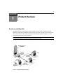
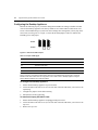
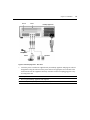
Digital Desktop
System
Installer/User Guide
For Technical Support:
www.avocent.com/support
Avocent Corporation
4991 Corporate Drive
Huntsville, Alabama 35805-6201 USA
Tel: +1 256 430 4000
Fax: +1 256 430 4031
590-422-001A
C Series
Avocent International Ltd.
Avocent House, Shannon Free Zone
Shannon, County Clare, Ireland
Tel: +353 61 715 292
Fax: +353 61 471 871
Email: [email protected]
INSTRUCTIONS
This symbol is intended to alert the user to the presence of important
operating and maintenance (servicing) instructions in the literature
accompanying the appliance.
DANGEROUS VOLTAGE
This symbol is intended to alert the user to the presence of uninsulated
dangerous voltage within the product’s enclosure that may be of sufficient
magnitude to constitute a risk of electric shock to persons.
Digital Desktop System
Installer/User Guide
C Series
Avocent, the Avocent logo, The Power of Being There and Reclaim Your
Desktops are registered trademarks of Avocent Corporation or its
affiliates. All other marks are the property of their respective owners.
© 2005 Avocent Corporation. All rights reserved.
590-422-001A
USA Notification
Warning: Changes or modifications to this unit not expressly approved by the party responsible for compliance
could void the user's authority to operate the equipment.
Note: This equipment has been tested and found to comply with the limits for a Class A digital device,
pursuant to Part 15 of the FCC Rules. These limits are designed to provide reasonable protection against
harmful interference when the equipment is operated in a commercial environment. This equipment generates,
uses and can radiate radio frequency energy and, if not installed and used in accordance with the instruction
manual, may cause harmful interference to radio communications. Operation of this equipment in a residential
area is likely to cause harmful interference in which case the user will be required to correct the interference at
his own expense.
Canadian Notification
This Class A digital apparatus complies with Canadian ICES-003.
Cet appareil numérique de la classe A est conforme à la norme NMB-003 du Canada.
Japanese Approvals
iii
T A B L E O F C ON T E N T S
Table of Contents
List of Figures .................................................................................................................. v
List of Tables .................................................................................................................. vii
Chapter 1: Product Overview.......................................................................................... 1
Features and Benefits ........................................................................................................................ 1
Digital extension up to 800 meters away.................................................................................... 2
DWorks Administration Utility ................................................................................................... 2
On-board audio support, USB and serial controller.................................................................. 2
On-board video support.............................................................................................................. 2
Remote Power Control ............................................................................................................... 2
Ethernet addressing .................................................................................................................... 2
Kensington Lock ......................................................................................................................... 2
Intrusion Detect option ............................................................................................................... 3
Loose Link protection ................................................................................................................. 3
Lower Total Cost of Ownership (TCO) ...................................................................................... 3
Safety Precautions ............................................................................................................................. 3
Chapter 2: Installation ..................................................................................................... 5
Getting Started ................................................................................................................................... 5
Supplied with the Desktop Appliance ......................................................................................... 5
Supplied with the PCI Add In Card ............................................................................................ 5
Additional items needed.............................................................................................................. 5
Recommended configuration ...................................................................................................... 5
Cable/network specifications...................................................................................................... 6
Remote Power Control option .................................................................................................... 6
Installing the Digital Desktop System................................................................................................ 7
Configuring the Desktop Appliance.......................................................................................... 12
Installing Drivers ............................................................................................................................. 16
Identifying/Pairing Units ................................................................................................................. 16
Relocating the Computer ................................................................................................................. 16
Recommended Deployment.............................................................................................................. 16
iv
Digital Desktop System Installer/User Guide
T A B L E O F C ON T E N T S
Chapter 3: Operations ................................................................................................... 17
Overview .......................................................................................................................................... 17
LED identification .................................................................................................................... 17
LED Definitions ............................................................................................................................... 18
Remote Power Control ............................................................................................................. 19
Using the Hotkey Feature ................................................................................................................ 20
Appendices..................................................................................................................... 23
Appendix A : Troubleshooting ......................................................................................................... 23
Appendix B : UTP Cabling .............................................................................................................. 26
Appendix C : Technical Specifications ............................................................................................ 29
Appendix D : Technical Support...................................................................................................... 30
Index................................................................................................................................ 31
v
LIST OF FIGUR ES
List of Figures
Figure 1.1: Digital Desktop Basic System......................................................................................... 1
Figure 2.1: Basic Digital Desktop System Configuration ................................................................. 7
Figure 2.2: PCI Add In Card Jumpers .............................................................................................. 8
Figure 2.3: PCI Add In Card Device Jumper Configuration ............................................................ 8
Figure 2.4: Configuration of Auxiliary Power Jumpers.................................................................. 10
Figure 2.5: Installing the PCI Add In Card..................................................................................... 11
Figure 2.6: Connecting Cables to the PCI Add In Card ................................................................. 11
Figure 2.7: Video and FLASH Jumpers .......................................................................................... 12
Figure 2.8: Installing a Third Party PCI Add In Card.................................................................... 13
Figure 2.9: Desktop Appliance - Right Side View ........................................................................... 14
Figure 2.10: Desktop Appliance - Rear View.................................................................................. 15
Figure 3.1: LED Identification - Desktop Appliance - Right Side................................................... 17
Figure 3.2: LED Identification - PCI Add In Card ......................................................................... 18
Figure 3.3: Resetting the Computer ................................................................................................ 20
vi
Digital Desktop System Installer/User Guide
vii
LIST OF TABLES
List of Tables
Table 2.1: Device Jumper Definition................................................................................................. 9
Table 2.2: Jumper FLASH Types..................................................................................................... 12
Table 3.1: Hotkey Command Table ................................................................................................. 21
Table A.1: Desktop Appliance/PCI Add In Card Troubleshooting ................................................. 23
Table B.1: Digital Desktop System Wiring Standards..................................................................... 26
Table B.2: Link Distances................................................................................................................ 27
Table C.1: Digital Desktop System Technical Specifications.......................................................... 29
viii
Digital Desktop System Installer/User Guide
1
CHAPTER
1
Product Overview
Features and Benefits
The Digital Desktop System enables IT professionals to relocate a user’s computer up to 800
meters away while still providing the user the same PC experience. The basic system consists of a
host card (PCI Add In Card), interconnecting link and a Desktop Appliance (Figure 1.1). This
provides centralized control of PC resources.
NOTE: The information contained in this guide is for use with all C Series Digital Desktop Systems. However,
where information pertains only to specific models, the model number is noted.
Rack Mounted PCs
and Blades
Gigabit
Ethernet
Switch
User 2
Desktop
Appliance
User 1
Desktop
Appliance
Desktop
Appliance
Administrator
Figure 1.1: Digital Desktop Basic System
2
Digital Desktop System Installer/User Guide
Digital extension up to 800 meters away
The Desktop Appliance and PCI Add In Card connect over fiber optic (applicable DDL21xx or
DDC21xx Desktop Appliance models) or CAT 5, 5e or 6 cable (applicable DDL20xx or DDC20xx
Desktop Appliance models). Reliable digital extension is available as far as 800 meters away from
the computer.
DWorks Administration Utility
The DWorks Administration Utility provides a simple and convenient way to set up and manage
Digital Desktop Systems deployed over a switched network. For added security, the DWorks
Administration Utility is not supplied with the standard Digital Desktop System distribution.
Contact your Avocent sales representative for more information.
On-board audio support, USB and serial controller
The Desktop Appliance is supplied with a built in audio adaptor and a USB 2.0 controller. The
USB 2.0 controller is provided with four access ports. A serial Universal Asynchronous Receiver/
Transmitter (UART) is also provided through an EIA-232 DB9 connector. For added security and
system control, the audio, USB and serial support devices can be independently disabled using
jumper settings on the PCI Add In Card or using the DWorks Administration Utility.
On-board video support
The Desktop Appliance is supplied with a built-in video adaptor providing digital resolutions of up
to 1280 x 1024 at 60 Hz or analog resolutions of up to 2048 x 1536 at 60 Hz. Integrating the video
adaptor also reduces video degradation to levels beneath user detection. This may also be
accomplished with the installation of a user-supplied PCI video adaptor card.
Remote Power Control
An optional Remote Power Control (RPC) cable enables the system to have the same power and
reset functions that are available on the front panel of the host PC. Contact your Avocent sales
representative for information regarding your specific configuration.
Ethernet addressing
Both the Desktop Appliance and the PCI Add In Card are Ethernet addressable as Layer 2 devices.
This allows the Digital Desktop System to be connected over a 1 Gb Ethernet switched network.
Because of the network bandwidth requirements, Avocent recommends that the Digital Desktop
System be connected on a dedicated network. Connection between the PCI Add In Card and the
Desktop Appliance may be established over a point-to-point or switched network topology.
Kensington Lock
For installations requiring increased security, the Desktop Appliance can be connected to a usersupplied Kensington Lock.
Chapter 1: Product Overview
3
Intrusion Detect option
The Intrusion Detect option allows the administrator to use the DWorks Administration Utility to
monitor access to the top cover of the Desktop Appliance. The Intrusion Detect option alerts the
administrator when the top cover is removed, even when the unit is powered down. If you have
purchased the Intrusion Detect option, please refer to the installation instructions supplied for
further details.
Loose Link protection
The Digital Desktop System Loose Link feature allows for momentary interruptions of the
connection between the computer and the Desktop Appliance without system lockup.
Lower Total Cost of Ownership (TCO)
The Digital Desktop System delivers significantly lower TCO when compared to traditional
distributed computer systems. Centralized maintenance enables greater security and convenience as
well as reduced workplace disruption and down-time. Relocating the computer away from the user
frees up valuable office space and reduces desktop power and heating, ventilation and airconditioning (HVAC) requirements.
Safety Precautions
To avoid potential video and/or keyboard problems when using Avocent products:
•
If the building has 3-phase AC power, ensure that the computer and monitor are on the same
phase. For best results, they should be on the same circuit.
To avoid potentially fatal shock hazard and possible damage to equipment, please observe the
following precautions:
•
Do not use a 2-wire extension cord in any configuration of this product.
•
Test AC outlets at the computer and monitor for proper polarity and grounding.
•
Use only with grounded outlets at both the computer and monitor. When using a backup
Uninterruptible Power Supply (UPS), power the computer, the monitor and the unit off
the supply.
NOTE: The AC inlet is the main disconnect.
•
Product configurations that are equipped with a laser device comply with the appropriate
safety standards including IEC 825. If the product variation that you have purchased does
contains a laser device, it is classified as a Class 1 laser product as defined by IEC 825.
4
Digital Desktop System Installer/User Guide
5
CHAPTER
2
Installation
Getting Started
Before installing your Digital Desktop System, refer to the following lists to ensure you have all
items that shipped with the product as well as other items necessary for proper installation.
Supplied with the Desktop Appliance
•
Power cord
•
2 DVI-I to VGA adaptors (supplied with Desktop Appliances that provide DVI-I video)
•
Read Me First
•
Installer/User Guide
•
Quick Install Guide
•
Service Level Agreement
Supplied with the PCI Add In Card
•
PS/2 keyboard/mouse “Y” cable
•
Low Profile bracket
Additional items needed
Either CAT 5 cable (DDC20xx models) or standard multimode fiber optic cable (DDC21xx
models) is required for correct operation of the Digital Desktop System. This cabling is usersupplied and commonly found in pre-existing network installations. If you are missing any of the
listed items from your shipment, contact Avocent Technical Support. For more information, see
Appendix D on page 30.
Recommended configuration
•
The recommended configuration requires at least two patch cables. One attaches the computer
to a patch panel. The other connects the Desktop Appliance to either an RJ-45 wall jack (applicable DDC20xx Desktop Appliance models) or to the appropriate fiber wall jack (applicable
DDC21xx Desktop Appliance models).
6
Digital Desktop System Installer/User Guide
•
During configuration, you may choose to keep the computer and Desktop Appliance together
until configuration is complete. In this case, you will need to utilize one of the patch cables to
complete this portion of the configuration. After successful configuration of the Desktop
Appliance, relocate the computer from the user’s desktop to your centralized computer facility.
Cable/network specifications
•
The cable interface between a remote DDC20xx Desktop Appliance and the computer may be
CAT 5 Unshielded Twisted Pair (UTP), CAT 5e or CAT 6 cable. References to CAT 5 cable
throughout this manual refer to supported types. For more information regarding supported
cabling, see Appendix B on page 26.
•
For a DDC21xx Desktop Appliance, the cable interface must be standard multimode fiber
optic cabling that is IEEE 802.3z/1000BASE-SX compliant. Fiber optic cabling is used
throughout this manual to denote all supported types. Interfaces to the Desktop Appliance and
PCI Add In Card are implemented using an LC connection. For more information, see
Appendix B on page 26.
NOTE: The LC receptacles of the DDP2100 PCI Add In Card and the DDC21xx Desktop Appliance are shipped
with protective dust covers installed. These protective covers should be retained and reinstalled whenever the
fiber cable is removed, or if the product is packaged for storage or shipment.
•
The link cabling between the remote Desktop Appliance and the computer must be either a
point-to-point connection or connected through a 1 Gb Ethernet switch. If it is a point-to-point
connection, no other active devices, such as routers or hubs, may be present in the link.
•
For switched applications, the units must be connected through a 1 Gb Ethernet switch.
Avocent recommends that such connections should be maintained on a dedicated network.
•
A maximum of three cable junctions is supported between the Desktop Appliance or PCI Add
In Card and the next buffering device.
Remote Power Control option
In many instances, the interface between the front panel power switch and the motherboard is
unique to the computer model. Remote Power Control (RPC) cables are designed to operate with
specific computer models and create the interface between the PCI Add In Card and the computer.
NOTE: If you wish to purchase the RPC option for your Digital Desktop System, discuss your requirements with
an Avocent sales representative to order an RPC Cable Kit that is applicable to your system.
Similarly, different jumper settings may be required on the PCI Add In Card depending on the
model of computer you are operating. Your RPC Cable Kit contains detailed instructions that
indicate how to install and configure power control for your computer model.
Chapter 2: Installation
7
If you did not receive an RPC Cable Kit with your RPC cable, or if you have changed the type of
computer you are adding to the Digital Desktop System, visit our web site or contact Avocent
Technical Support before proceeding with the installation.
NOTE: The Desktop Appliance and your computer should be powered down before servicing the unit. Always
disconnect the power cord from the wall outlet.
Installing the Digital Desktop System
Figure 2.1 illustrates one possible configuration for your Digital Desktop System. The following
procedures outline how to successfully install your PCI Add In Card and Desktop Appliance.
PCI Add In Card
Desktop Appliance
Figure 2.1: Basic Digital Desktop System Configuration
CAUTION: To reduce the risk of electric shock or damage to your equipment Disconnect the power from the unit by unplugging the power cord from either the electrical outlet or the unit.
To prepare your computer for installation:
1.
If your computer has integrated video or audio, restart the computer and change the BIOS settings to PCI or Autodetect. Consult your computer documentation for specific instructions.
2.
Save your changes and power down the computer.
3.
Disconnect the keyboard, monitor, mouse and any other USB devices or audio components
that will be active at the user’s desktop.
8
Digital Desktop System Installer/User Guide
4.
Remove the computer cover to access the interface cards.
5.
If applicable, remove the current video and audio interface cards from the computer.
To configure the PCI Add In Card:
Several jumpers and two sets of connectors on the PCI Add In Card are used to configure your
Digital Desktop System. An optional short bracket is also provided to accommodate a low profile
PCI form factor.
1.
Determine which PCI slot form factor is available for you to install the PCI Add In Card. The
PCI Add In Card is shipped with a tall bracket mounted for use with standard PCI slots.
A short bracket is provided for low profile PCI slots. You may need to change the bracket
before installing the PCI Add In Card.
2.
Configure the PCI device jumpers on the PCI Add In Card. These jumpers allow you to selectively disable certain components of your Digital Desktop System. The factory default is set
with all components enabled. Figure 2.3 identifies the enable/disable positions for each
jumper. Table 2.1 identifies which PCI devices are controlled by each jumper.
Device Jumpers
Auxiliary Power Jumpers
Figure 2.2: PCI Add In Card Jumpers
J1
J2
J3
J4
J5
J6
Enable
J7
J8
J9
1
2
Disable
Figure 2.3: PCI Add In Card Device Jumper Configuration
3
Chapter 2: Installation
9
Table 2.1: Device Jumper Definition
Jumper
PCI Device
J1
USB
J2
Audio
J3
Slot 0 (DDL & DDC models only)
J4
Video
J5
Slot 1 (DDC models only)
J6
Reserved
J7
UART
J8
Remote FLASH write
J9
Local FLASH write
NOTE: The DWorks Administration Utility can also be used to selectively disable these PCI devices. Both the
physical jumper and the FLASH setting must be enabled in order for a PCI device to be enabled.
NOTE: The DWorks Administration Utility is required to access the FLASH contents. Local FLASH write enable
refers to running the DWorks Administration Utility on the Digital Desktop System being configured. Remote
FLASH write enable refers to configuration of a PCI Add In Card or Desktop Appliance using the PCI device’s
Ethernet address over a switched network.
3.
If you purchased the RPC option for your Digital Desktop System, please refer to the instructions provided with the cable specific to your computer. Figure 2.4 identifies the jumpers used
to select the appropriate auxiliary power setting. The factory default setting is for use of +3.3 V
auxiliary power. One of the listed auxiliary power sources must be available in order to use the
RPC option.
10
Digital Desktop System Installer/User Guide
J17
Ext
J14
+5V
WOL
Aux
PCI +3.3V Aux (Default)
J17
J14
Ext
+5V
WOL
Aux
External +5V
J17
Ext
J14
+5V
WOL
Aux
External +3.3V
Figure 2.4: Configuration of Auxiliary Power Jumpers
If you do not have the instructions provided with your RPC cable, or if you have changed the type
of computer you will be using with your Digital Desktop System, contact Avocent Technical
Support for further information.
Chapter 2: Installation
11
To install the PCI Add In Card:
1.
Install and secure the PCI Add In Card into the available PCI slot.
PCI Add In Card
Figure 2.5: Installing the PCI Add In Card
2.
Close and secure the cover of the computer.
3.
Connect the PS/2 keyboard/mouse “Y” cable between the PCI Add In Card and the appropriate
PS/2 ports on your computer.
PS/2 “Y” Cable
Figure 2.6: Connecting Cables to the PCI Add In Card
12
Digital Desktop System Installer/User Guide
Configuring the Desktop Appliance
Perform the following steps if you wish to change the FLASH write settings or disable on-board
video for the Desktop Appliance. The factory default is set to allow both local and remote write
access to the FLASH settings. If you do not wish to change these settings then you may skip to the
next section, Installing Drivers. Figure 2.7 shows the FLASH jumpers. Table 2.2 indicates the
FLASH type for each jumper.
J11
J12
J13
1
Enable
2
Disable
3
Figure 2.7: Video and FLASH Jumpers
Table 2.2: Jumper FLASH Types
Jumper
FLASH Type
J11
On-board video enable
J12
Remote FLASH write
J13
Local FLASH write
NOTE: The DWorks Administration Utility is required to access the FLASH contents. Local FLASH write enable
refers to execution of the DWorks Administration Utility from the Digital Desktop System being configured.
Remote FLASH write enable refers to configuration of a PCI Add In Card or Desktop Appliance using the
device’s Ethernet address over a switched network.
To configure the Desktop Appliance:
1.
Ensure that the Desktop Appliance is powered down.
2.
Locate and remove the four screws (two on each side of the unit) that allow you to remove the
top housing.
3.
Configure the jumpers for the desired setting.
4.
Install and secure the top housing.
To install a third party PCI Add In Card:
1.
Ensure that the Desktop Appliance is unplugged and powered off.
2.
Locate and remove the four screws (two on each side of the unit) that allow you to remove the
top cover.
3.
Remove the top cover.
Chapter 2: Installation
13
4.
Remove the PCI slot blanking plate of the desired slot.
5.
Install your third party PCI Add In Card into the Desktop Appliance as shown in Figure 2.8,
and secure it with the screw removed from the blanking plate.
Slot 1
Slot 0
Figure 2.8: Installing a Third Party PCI Add In Card
6.
Reassemble the Desktop Appliance and secure the top cover with the four screws removed in
step 2.
To configure the Digital Desktop System:
1.
Connect the Desktop Appliance to the PCI Add In Card inside the computer, using an appropriate patch cable.
2.
Connect the keyboard, mouse, monitor and any other USB or audio components to the appropriate connectors on the Desktop Appliance.
14
Digital Desktop System Installer/User Guide
Desktop Appliance
Kensington
Security Slot
Serial
Connection
VGA Video
DVI Video
Keyboard
USB
Keyboard
PS/2
Figure 2.9: Desktop Appliance - Right Side View
Chapter 2: Installation
Slot 0
Slot 1
15
Desktop Appliance
Microphone
Stereo
Speakers
Figure 2.10: Desktop Appliance - Rear View
3.
Locate the power cord that was supplied with your Desktop Appliance and plug one end into
the appliance. Plug the other end of the power cord into an appropriate AC wall outlet. This
outlet must be near the equipment and easily accessible to allow for unplugging prior to any
servicing of the unit.
NOTE: The power cord serves as the main disconnect.
4.
Power up the Desktop Appliance and computer.
NOTE: The computer will power up automatically if the RPC option is installed.
16
Digital Desktop System Installer/User Guide
Installing Drivers
To install drivers:
1.
Once the computer boots, follow the operating system prompts for the installation of new hardware and system drivers. Drivers for devices built into the Desktop Appliance can be downloaded from the Avocent Technical Support web site. For more information, see Appendix D
on page 30.
2.
Once the Digital Desktop System is fully configured, shut down the computer to ensure a correct software exit.
3.
Power down your Desktop Appliance.
4.
Disconnect the patch cable and all of the attached peripherals from both the computer and the
Desktop Appliance.
Identifying/Pairing Units
If the system is to be connected over a 1 Gigabit (Gb) Ethernet switched network, the DWorks
Administration Utility is required to pair the system components. A barcode reader can be used to
collect MAC addresses from the PCI Add In Card and the Desktop Appliance. The DWorks
Administration Utility can store user identification data in FLASH memory.
Relocating the Computer
To relocate the computer:
1.
Move the computer to the centralized computer facility where it will reside.
2.
Connect the PCI Add In Card to your patch panel or other appropriately terminated connection
point. Ensure that the connection meets the Digital Desktop System cabling requirements.
3.
Reconnect power and computer interfaces, such as network and fiber channels, directly to the
computer as usual.
Recommended Deployment
The Desktop Appliance is deployed at the user’s desktop, enabling access to all peripherals and
attached devices. The computer is safely relocated to a centralized computer facility.
To deploy the Desktop Appliance:
1.
At the user’s desktop, connect an available patch cable from the Desktop Appliance into the
wall jack.
2.
Reconnect the keyboard, mouse, monitor and any other USB or audio components to the
appropriate connectors on the Desktop Appliance.
3.
Power up the Desktop Appliance first, then the computer. Verify the boot process with the
user’s video monitor.
17
CHAPTER
3
Operations
Overview
Operating the computer through the Digital Desktop System is no different than working directly
connected to your computer. All peripherals operate as if directly connected, though the computer
is located at a distance.
LED identification
The following figures describe LED orientation and identification on the Desktop Appliance and
PCI Add In Card. Reference these LEDs to determine the operational status of your Digital
Desktop System.
FLASH Access
System Link
Physical Link
Power
Figure 3.1: LED Identification - Desktop Appliance - Right Side
18
Digital Desktop System Installer/User Guide
Power
Physical Link
System Link
FLASH Access
Figure 3.2: LED Identification - PCI Add In Card
LED Definitions
Power
The Power LED is off when no power is supplied to the PCI Add In Card or Desktop Appliance.
When auxiliary power is applied, this LED is dimly illuminated. When the main power is on, this
LED is fully illuminated.
Physical Link
The Physical Link LED is illuminated when a physical link is established between the Desktop
Appliance and the PCI Add In Card. It is fully illuminated when a 1 Gigabit (Gb) link has been
established with another Digital Desktop System component or a buffer device such as a 1 Gb
Ethernet switch. The Physical Link LED blinks rapidly if the unit is connected to a device that
provides a 100 Megabit (Mb) link and slowly when connected to a device providing a 10 Mb link.
Therefore, if the Physical Link LED is blinking, the system will not function correctly since a 1 Gb
link has not been established.
NOTE: For DDL21xx fiber models, the Physical Link LED is fully illuminated when the presence of LASER light
indicates that a fiber optic connection is detected.
System Link
The System Link LED is off when no power is available to the PCI Add In Card or Desktop
Appliance. It blinks rapidly when power is available without a system link connection. It blinks
slowly to indicate that a system link is established but the unit(s) on either end of the connection is
Chapter 3: Operations
19
in a power saving mode. The System Link LED is constantly illuminated when the system is in
normal operation.
NOTE: The information provided for the System Link LED is also applicable to the blue LED on the front panel of
the Desktop Appliance.
FLASH Access
The FLASH Access LED is normally not illuminated. It is only illuminated when the FLASH
memory of the PCI Add In Card or Desktop Appliance is accessed. This is only the case when the
Digital Desktop System is accessed using the DWorks Administration Utility.
Remote Power Control
Powering the Desktop Appliance and computer
If you have installed the optional Remote Power Control (RPC) feature, you can power your system
on and off from the Desktop Appliance by pressing the Power button on the front panel. The PCI
Add In Card will power down the computer approximately 20 seconds after the Power button has
been pressed on the Desktop Appliance.
NOTE: This time can vary. For more information on timing, refer to the Loose Link feature in the DWorks
Administration Utility.
The Power LED on the front panel of the Desktop Appliance is not illuminated when the Desktop
Appliance is powered down. It will blink rapidly when power is applied without a system link. It
blinks slowly to indicate that a system link is established but the unit(s) on either end of the
connection is in a power saving mode. The System Link LED is constantly illuminated when the
system is in normal operation.
NOTE: Follow your operating system’s instructions for shutdown prior to powering down the system, just as you
would if directly connected to your computer.
20
Digital Desktop System Installer/User Guide
Resetting the computer from the Desktop Appliance
If you have installed the optional RPC feature and your computer supports a Reset button, you can
reset your computer from the Desktop Appliance. To do this, depress the Reset button on the front
panel of the Desktop Appliance. Your attached computer will reset in three to five seconds.
Remote Power Remote Reset
Button
Button
Figure 3.3: Resetting the Computer
Using the Hotkey Feature
You can initiate certain operations on the Digital Desktop System by using the Hotkey commands.
When you enter a Hotkey command on a keyboard connected to the Desktop Appliance PS/2
keyboard jack, the Desktop Appliance acknowledges the command by blinking a pattern with the
keyboard Num Lock, Caps Lock and Scroll Lock LEDs. Table 3.1 shows available Hotkey
commands and LED indications.
To use the Hotkey feature:
1.
Activate the Hotkey feature by pressing and holding down the Scroll Lock key and then pressing the F12 key. Release the two keys in any order. Initially all the keyboard lock status LEDs
will blink to indicate that the Hotkey feature is active, followed by the patterns as shown in the
following table.
2.
Once the Hotkey feature is active, enter a Hotkey command. The LEDs will blink the pattern
associated with the command.
3.
Press Enter to execute the last valid Hotkey command. If the command you enter is not valid,
the system will not execute an operation. Once the system executes a Hotkey command, the
keyboard interface automatically exits the Hotkey feature.
Chapter 3: Operations
4.
21
Terminate the Hotkey feature by pressing the Esc key should you no longer wish to enter a
Hotkey command. After the keyboard interface has exited the Hotkey feature, the lock status
LEDs will return to the state they were in prior to hotkey activation.
NOTE: Properly terminating the Hotkey feature will prevent unexpected results.
Table 3.1: Hotkey Command Table
Hotkey Command
Key Sequence
Activate hotkey
Press/Hold Scroll Lock Blink
Press F12
Blink
Blink
Power down computer
S or 0
Blink
Off
Off
Power up computer
P or 1
Off
Blink
Off
Reset computer
R
Off
Off
Blink
Execute Hotkey command
Enter
Previous
Previous
Previous
Previous
Previous
Previous
Execute hotkey w/o command Esc
Num Lock LED Caps Lock LED Scroll Lock LED
Equipment requirements
Ensure that the equipment on both ends of the link can support the Hotkey feature. The Desktop
Appliance must have a keyboard that is connected to the PS/2 keyboard connector in order to use
Hotkey commands.
The Hotkey feature must not be disabled in FLASH memory by the DWorks Administration
Utility. For the Hotkey power down, power up and computer reset commands to execute, the RPC
cabling must correctly connect the PCI Add In Card and the computer.
22
Digital Desktop System Installer/User Guide
23
APP ENDICE S
Appendices
Appendix A: Troubleshooting
Table A.1: Desktop Appliance/PCI Add In Card Troubleshooting
Desktop Appliance/PCI Add In Card Power LED not lit
Verify that the unit/host computer is plugged into an appropriate AC outlet.
Desktop Appliance/PCI Add In Card Physical Link LED not lit
Verify that the link cable is connected to one of the following:
•
A PCI Add In Card that is installed in a host computer. The host computer must at a minimum
provide standby power.
•
A Desktop Appliance that is plugged into an appropriate AC outlet.
•
A 1 Gigabit (Gb) Ethernet switch that is powered up.
Desktop Appliance/PCI Add In Card Physical Link LED is blinking
A blinking Physical Link LED indicates that the link is connected to a 100 Mb device (rapid blink), or
a 10 Mb device (slow blink). Reconnect the link directly to the PCI Add In Card/Desktop Appliance,
or through a 1 Gb Ethernet switch.
Desktop Appliance/PCI Add In Card System Link LED not lit
Verify that the destination MAC address of both the Desktop Appliance and the PCI Add In Card
have been properly paired. This requires the use of the DWorks Administration Utility. If the link is
connected through a 1 Gb Layer 1 switch, then verify that the two ports being used for the Digital
Desktop System are properly configured.
Computer will not boot
Ensure that the computer is powered up.
Check the LED status.
Verify that all cables are properly connected.
Reinstall the PCI Add In Card into a different PCI slot.
Ensure that the video adaptor is enabled in the Desktop Appliance and the PCI Add In Card.
Ensure the integrity of the PCI Add In Card cabling. Test cabling with Time Domain Reflectometry
(TDR) or other appropriate cable test device.
24
Digital Desktop System Installer/User Guide
Table A.1: Desktop Appliance/PCI Add In Card Troubleshooting (Continued)
No video
Ensure that the computer is powered.
Ensure that all video cards are removed from the computer.
Check the PCI Add In Card and Desktop Appliance LEDs to ensure that computer to Desktop
Appliance communication is functioning.
Ensure the integrity of the PCI Add In Card cabling. Test cabling with TDR or other appropriate cable
test device.
Ensure that the on-board video or the slot being used for video has not been disabled on the PCI
Add In Card, Desktop Appliance or using the DWorks Administration Utility.
Reinstall the PCI Add In Card into a different PCI slot in the computer.
Check your computer’s BIOS settings and ensure that they are set to PCI video or Autodetect.
Disable on-board graphics adaptor in the operating system and/or BIOS.
Reset the BIOS to the default setting and reboot to allow Plug and Play BIOS to detect devices.
Uninstall and reinstall video drivers.
No audio
Plug headphones, if used, into the Desktop Appliance audio output jack.
If you are using speakers, ensure that they are powered and plugged into the Desktop Appliance
audio output jack.
Ensure that no other audio cards are installed in the computer.
Ensure that audio has not been disabled in the PCI Add In Card or DWorks Administration Utility.
Check the PCI Add In Card and Desktop Appliance LEDs to ensure computer to Desktop Appliance
communication is functioning.
Check your computer’s BIOS settings and ensure that your on-board audio, if any, is disabled.
Ensure that your audio drivers are properly installed. Ensure that any running application software
that is playing music does not have the speaker muted.
Audio files are audible, CDs are not
Find and enable the Enable Digital Audio option within your operating system.
Appendices
25
Table A.1: Desktop Appliance/PCI Add In Card Troubleshooting (Continued)
USB peripheral is inoperable
Ensure that your USB peripherals are plugged into the USB ports of the Desktop Appliance in
accordance with the peripheral manufacturer’s guidelines.
Check PCI Add In Card and Desktop Appliance LEDs to ensure computer to Desktop Appliance
communication is functioning.
Ensure that USB has not been disabled in the PCI Add In Card or DWorks Administration Utility.
Ensure that your operating system supports USB connections.
Ensure that the device being connected is USB 2.0 compliant and installed according to the
manufacturer’s guidelines.
Video/Audio/USB performance is sluggish
Ensure the integrity of the PCI Add In Card cabling. Test cabling with TDR or other appropriate cable
test device.
Check the cable connections at the Desktop Appliance and the PCI Add In Card and any other
connections or patches in that path.
Check for correct driver operations.
PS/2 device is not functioning properly
Ensure that the keyboard and mouse are plugged into the appropriate Desktop Appliance ports.
Ensure that PS/2 “Y” cable is correctly attached from the rear of the PCI Add In Card to the PS/2
input on the back of the computer.
Ensure that the PS/2 device functions properly when connected directly to the computer.
26
Digital Desktop System Installer/User Guide
Appendix B: UTP Cabling
The performance of the Digital Desktop System depends on high-quality connections. Poorly
installed or maintained cabling can diminish the performance of the Digital Desktop System.
NOTE: This appendix is for information purposes only. Please consult with your local code officials and/or
cabling consultants prior to any installation.
Depending on the model you have chosen, the Digital Desktop System operates with either
Unshielded Twisted Pair (UTP) or standard multimode fiber optic cabling. Both of these cabling
types are discussed in the following sections.
UTP copper cabling
The following are basic definitions for the three types of UTP cabling that the Digital Desktop
System supports:
•
CAT 5 UTP (4-pair) high performance cable consists of twisted pair conductors, used primarily for data transmission. The twisting of the pairs gives this cable some immunity from the
infiltration of unwanted interference. CAT 5 cable is generally used for networks running at 10
or 100 Mbps.
•
CAT 5e (enhanced) cable has the same characteristics as CAT 5, but is manufactured to somewhat more stringent standards.
•
CAT 6 cable has the same characteristics as CAT 5e, but is manufactured to a higher standard.
Wiring standards
There are two supported wiring standards for 8-conductor (4-pair) RJ-45 terminated UTP cable:
EIA/TIA 568A and B. These standards apply to installations with CAT 5, 5e and 6 cable
specifications. The Digital Desktop System supports either of these wiring standards.
Table B.1: Digital Desktop System Wiring Standards
Pin
EIA/TIA 568A
EIA/TIA 568B
1
white/green
white/orange
2
green
orange
3
white/orange
white/green
4
blue
blue
5
white/blue
white/blue
6
orange
green
7
white/brown
white/brown
8
brown
brown
Appendices
27
Standard multimode fiber cabling
For the fiber optic cable models of the Digital Desktop System, the cable interface should be IEEE
802.3z 1000BASE-SX standard multimode fiber optic cabling. Table B.2 shows the minimum link
distances that must be supported by cables that are compliant with this standard.
Table B.2: Link Distances
Fiber Type
Modal Bandwidth
Maximum Link Distance
62.5 µm MMF
160 MHz*km
220 meters
62.5 µm MMF
200 MHz*km
275 meters
50 µm MMF
400 MHz*km
500 meters
50 µm MMF
500 MHz*km
500 meters
Premium, or high grade, fiber cables are available, enabling reliable links of 800 meters or greater.
If you expect your link to exceed 550 meters, contact Avocent Technical Support for information
regarding this higher grade of fiber.
Fiber patch cables used with the Digital Desktop System must have an LC connector on the end
that attaches to the Desktop Appliance. Optical connectors selected for use elsewhere in the link,
such as at the wall interface, are at the installer’s discretion.
NOTE: To avoid contamination, do not touch the optical surfaces of patch cable connectors with your fingers.
The oil from your fingertips will adhere to the connector, impairing link performance.
NOTE: The LC receptacles of the DDP2100 PCI Add In Card and the DDC21xx Desktop Appliance unit are
shipped with protective dust covers installed. These protective covers should be retained and reinstalled
whenever the fiber cable is removed, or if the product is packaged for storage or shipment.
Cabling installation, maintenance and safety tips
The following is a list of important safety considerations that should be reviewed prior to installing
or maintaining your cables:
•
Keep all CAT 5 runs to a maximum of 100 meters each.
•
Maintain the twists of the pairs all the way to the point of termination, or no more that one-half
inch untwisted. Do not skin off more than one inch of jacket while terminating.
•
If bending the cable is necessary, make it gradual with no bend sharper than a one inch radius.
Allowing the cable to be sharply bent or kinked can permanently damage the cable’s interior.
•
Dress cables neatly with cable ties, using low to moderate pressure. Do not over-tighten ties.
•
Cross-connect cables where necessary, using rated punch blocks, patch panels and components. Do not splice or bridge cable at any point.
28
Digital Desktop System Installer/User Guide
•
Keep CAT 5 cable as far away as possible from potential sources of electromagnetic interference (EMI), such as electrical cables, transformers and light fixtures. Do not tie cables to electrical conduits or lay cables on electrical fixtures.
•
Test each installed segment with a cable tester. “Toning” alone is not an acceptable test.
•
Always install jacks so as to prevent dust and other contaminants from settling on the contacts.
The contacts of the jack should face up on the flush mounted plates, or left/right/down on surface mount boxes.
•
Always leave extra slack on the cables, neatly coiled in the ceiling or nearest concealed location. Leave at least five feet at the work outlet side and 10 feet at the patch panel side.
•
For CAT 5 installations, choose either 568A or 568B wiring standard before beginning. Wire
all jacks and patch panels for the same wiring scheme. Don’t mix 568A and 568B wiring in the
same installation.
•
For fiber optic model installations, choose a supported wiring standard before beginning. Configure all jacks and patch panels for the standard you have chosen. Do not mix fiber optic
cabling types in a single installation.
•
Always obey all local and national fire and building codes. Be sure to firestop all cables that
penetrate a firewall. Use plenum rated cable where it is required.
Appendices
Appendix C: Technical Specifications
Table C.1: Digital Desktop System Technical Specifications
PCI Add In Card Specifications
PCI
Available PCI slot, PCI standard version 2.3 (Alternate bracket provided to
accommodate PCI Low Profile Version 2.3).
Operating Systems
Red Hat® Linux® 7.1, Windows® 95/98, Windows NT®, 2000, ME and
XP. (Driver installation may be required to enable some features of the
Digital Desktop System. Additionally, not all features are available with all
operating systems. Refer to your operating system documentation.)
Minimum Requirements
As defined by your operation system.
Cabling
100 M CAT 5/5e/6, or 550 M IEEE 802.3z 1000BASE-SX fiber, configured
in a point-to-point connection. A maximum of three cable junctions
between the PCI Add In Card and Desktop Appliance or buffering device.
Desktop Appliance Specifications
Video
Video adaptor with 32 MB RAM capable of digital resolutions of up to
1280 x 1024 at 60 Hz or analog resolution of up to 2048 x 1536 at 60Hz
on two ports (DDL2x50 models).
Audio
Stereo line in and out; microphone in.
Peripherals
Supports standard USB 2.0 compliant devices; PS/2 keyboard/mouse;
Standard 9-pin serial port.
HxWxD
7.4 x 21.1 x 39.0 cm.
Shipping Weight
5.0 kg (factory configuration).
Voltage
100 to 240 VAC.
Power Frequency
50 to 60 Hz.
Environmental
Temperature
Operating: 10o to 35oC (50o to 95oF), Storage -40o to 65oC (-40o to
149oF), 20% to 80% (noncondensing).
29
30
Digital Desktop System Installer/User Guide
Appendix D: Technical Support
Our Technical Support staff is ready to assist you with any installation or operating issues you
encounter with your Avocent product. If an issue should develop, follow the steps below for the
fastest possible service.
To resolve an issue:
1.
Check the pertinent section of this manual to see if the issue can be resolved by following the
procedures outlined.
2.
Check our web site at www.avocent.com/support to search the knowledge base or use the
on-line service request.
3.
Call the Avocent Technical Support location nearest you.
31
Index
INDE X
Power Control 10
A
Audio
9, 16
7
L
Autodetect
LED
Caps Lock 20
B
Definitions
7
BIOS settings
18
19
Identification 17
Num Lock 20
Physical Link 18, 23
Power 18, 23
Scroll Lock 20
System Link 18
Local FLASH write 9, 12
FLASH Access
D
Drivers
16
Installing
DWorks
16
DWorks Administration Utility 9, 12, 16, 19, 21,
23, 24, 25
F
Loose Link
Fiber cabling
Multimode
FLASH
19
Protection 3
Feature
27
12
FLASH write
P
12
Pairing
H
Hotkeys
Units
20
16
patch cables 5
I
PCI Add In Card
Interface cards
PCI Device
Audio
9
PCI slot 8, 11
Power LED 19
7
interface cards
1
7
R
J
Jumper 8,
Configuration
settings
Jumpers
Remote FLASH write
9, 12
6
8
9, 12
Remote Power Control, see RPC
RPC
9
Cable Kit
Custom 6
6
32
Digital Desktop System Installer/User Guide
S
V
Slot 0 9
video adaptor 7
Slot 1 9
W
U
Wiring standards
9
USB 9, 13, 16, 29
USB devices 7
UART
UTP
Cabling
26
Copper Cabling 26
26
Digital Desktop
System
Installer/User Guide
For Technical Support:
www.avocent.com/support
Avocent Corporation
4991 Corporate Drive
Huntsville, Alabama 35805-6201 USA
Tel: +1 256 430 4000
Fax: +1 256 430 4031
590-422-001A
C Series
Avocent International Ltd.
Avocent House, Shannon Free Zone
Shannon, County Clare, Ireland
Tel: +353 61 715 292
Fax: +353 61 471 871
Email: [email protected]