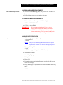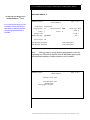
1
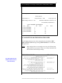
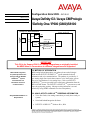
T M INTUITY AUDIX LX Configuration Note 9509 – RIP 02/10 Message Server Avaya Definity G3 / Avaya CM/Prologix / Definity One / IP600 (G600)/S8100 Avaya Definity G3 / ProLogix / Definity One / IP600 (G600)/S8100 Intuity Audix LX LINE TRUNK TDM BUS VOICE PATH Analog Interface Cards Call ID Outcalling Multiple Return to Operator Auto Attendant MWI On/Off Analog Cards CPU Minimum Software (see section 3.1) Minimum Software Release 1.0 IMPORTANT: This CN is for Support ONLY of Existing Integrations as originally installed. No NEW Sales or Conversions to different Integrations are Supported. With Inband integration, one pathway between the Prologix and the INTUITY TM system AUDIX LX transmits both call information and voice communications Avaya INTUITY AUDIX LX Requirements TM 1.0 METHOD OF INTEGRATION With Analog In-band integration, one pathway between the Prologix / IP600 and the INTUITY AUDIX LX TM system transmits both call information and voice communications. The pathway is provided by 2wire analog single-line circuits that connect to voice cards in the system. The voice card simulates 2-wire analog lines. Calls to an INTUITY AUDIX LX TM port are preceded by the called-party information from the PBX in DTMF format. The INTUITY AUDIX LX TM system answers and plays the appropriate greeting. Message-waiting indication is set and canceled by using DTMF commands over the same pathway. 2.0 AVAYA INTUITY AUDIX LX TM ORDERING INFORMATION • Voice Port Cards, four analog connections per card, (three cards per system) • Serial and Inband Integration Software • INTUITY AUDIX LX TM Software R1.x; R2.0 Disclaimer: Configuration Notes are designed to be a general guide that reflects AVAYA Inc.’s experience configuring its systems. These notes cannot anticipate every configuration possibility given the inherent variations in all hardware and software products. Please understand that you could experience a problem not detailed in a Configuration Note. If so, please notify the TAC/TSO at (408) 922-1822, and if appropriate, we will include the problem in our next revision. AVAYA Inc. accepts no responsibility for errors or omissions contained herein. 2 AVAYA Definity G3 / ProLogix / Definity One / IP600 (G600) / S8100 PBX hardware requirements 3.0 PBX HARDWARE REQUIREMENTS • TN742 or TN746B Analog ports, one per INTUITY AUDIX LX port • RJ11 telephone cords, one per analog voice port 3.1 PBX SOFTWARE REQUIREMENTS • Minimum Software: ProLogix or G3 V6.1 or higher • G3V 8 on DEFINITY ONE • G3V 9 on Avaya IP600 IMPORTANT: Supported integration features If you are integrating the IA LX to an Avaya IP600/G600/Definity1/S8100 PBX the internal AUDIX must be disabled. Once this is complete, please contact Avaya Tier 3 personnel so they can prevent unwanted alarms from generating. 4.0 SUPPORTED FEATURES • Call coverage to personal greeting - ring-no-answer - all calls NOTE: Definity/Avaya CM/ProLogix/IP600/S8100 does not support forward to Busy Greeting with modecode/in-band. Instead on a busy call forward the caller will hear a personal greeting. • Message-Waiting Indicator - lights - audible message waiting (optional PBX feature) • Automated Attendant • Outcalling, Paging • Multiple return-to-operator • Direct Call • Personal greeting of original-called party on a double-call forward using call coverage • Reply to message left by subscriber in internal telephone-answering mode • Call Sender The information contained in this document is provided by AVAYA Inc. to serve as a guide. See the disclaimer on page 1. 3 AVAYA Definity G3 / ProLogix / Definity One / IP600 (G600) / S8100 Configuring the PBX to integrate 5.0 CONFIGURING THE PBX FOR INTEGRATION The Voicemail system connects to the PBX as if it were a series of single line telephones. These single line telephones are referred to as analog ports that will be connected to the INTUITY voice portion of the voicemail system. Each port requires an RJ11 connection into the INTUITY. It is important that these analog ports have the ability to: Send and recognize DTMF tones, Forward on Busy and Ring-no-answer, Perform transfers using switch-hook flash, These analog ports must be configured in a hunt group. The hunt group is created in the PBX to allow the station to hunt to the next voice port. Call Information is passed from the PBX to the INTUITY using DTMF tones also called touch-tones. The call information should contain, at the minimum, the called party ID. For a better integration, the switch should pass Calling Party ID and the reason code why the call was forwarded. When a message is left for a users telephone, a second pattern of DTMF tones are passed to the PBX from the voice mail system using pre-determined codes to activate and de-activate message waiting. In addition, all users telephones must be programmed to forward to the Pilot Number of the voicemail system on a ring-no-answer and busy condition. In case MWI support is needed, the users telephone must have a message waiting lamp or LCD or stutter dial tone, programmed in order to determine a message has been left for the user. INTUITY LX TM will handle only the MWI ON/OFF code and it is the responsibility of the switch to interpret the code and switch MWI ON/OFF on the user’s telephone appropriately. Five tasks must be completed when programming the PBX to integrate. They are as follows: • Enable Mode Code Integration. • Configure each analog voice port. • Configure the analog voice ports into a UCD group. • Create call coverage path(s) that include the INTUITY AUDIX LX TM system access number. • Change subscriber's station programming to include the call coverage path. The information contained in this document is provided by AVAYA Inc. to serve as a guide. See the disclaimer on page 1. 4 AVAYA Definity G3 / ProLogix / Definity One / IP600 (G600) / S8100 5.1 MODE CODE SWITCH ADMINISTRATION • Feature Administration to Enable Mode-Code Integration. • Use the switch’s Customer Options form to enable mode code integration. Proceed as follows: 1. Enter the command: change system-parameters feature customer-options and make sure the G3 Version shown on the first line is V6 or higher. 2. Go to the page (page # will vary depending on the release you are using) where you will find the “Mode Code Interface?” field and ensure it is set Y. Define the analog voice ports that will connect to the INTUITY TM system AUDIX LX 5.2 ANALOG VOICE PORTS ADMINISTRATION • Define each integrated analog voice ports that will connect to the INTUITY AUDIX LX TM using the ADD STATION command. Sequential numbering is recommended. • The FEATURE OPTIONS should be configured as follows. Repeat for each analog port. Type: VMI Name: VOICEMAIL Tests? n LWC Reception? none LWC Activation? y Switchhook Flash? y Adjunct Supervision? y (Open Loop Disconnect) NOTE 1: You can substitute the name AUDIX, or Audix 1 or whatever name you want to use ion the name field. NOTE 2: Some older release may not permit you to change Adjunct Supervision to n All other fields can set to no or default. 5.3 HUNT GROUP ADMINISTRATION After all the analog lines to be connected to the INTUITY AUDIX LX TM ports are configured, they need to be installed into a Hunt Group. o Define the Hunt Group on the PBX by entering “add hunt-group <hunt group number> or “add hunt-group next” for the next available hunt group number. Configuring the hunt group as “ucd” is recommended. Below is an example of how an hunt group is configured: The information contained in this document is provided by AVAYA Inc. to serve as a guide. See the disclaimer on page 1. 5 AVAYA Definity G3 / ProLogix / Definity One / IP600 (G600) / S8100 ADD HUNT-GROUP 11 Configuring Hunt Group for the TM ports. INTUITY AUDIX LX Add hunt-group 11 Page 1 of 6 HUNT GROUP In our screen we use hunt-group 11 as an example. Please check with your administrator to determine what hunt Group Name: INTUITYLX Group Number: 11 Group Extension: 5000 group # is appropriate/available on your PBX. Queue? y Security Code: ISDN Caller Disp: grp-name3 Group Type: ucd ACD? n Vector? n COR: 1 TN: 1 Queue Length: 15 Calls Warning Threshold: Time Warning Threshold: Calls Warning Port: Time Warning Port: 3 Enter grp-name to specify the hunt group name be sent to the Note: originating user. This field is required when the ISDN-PRI option on the switch System-Parameters Customer-Options screen is enabled. Add hunt-group 11 Page 2 of 6 HUNT GROUP Message Center: none LWC Reception: none AUDIX Name: Messaging Server Name: The information contained in this document is provided by AVAYA Inc. to serve as a guide. See the disclaimer on page 1. 6 AVAYA Definity G3 / ProLogix / Definity One / IP600 (G600) / S8100 Add hunt-group 11 Page 3 of 6 HUNT GROUP Group Number: 11 Group Extension: 5000 Member Range Allowed: 1 - 999 Group Type: ucd Administered Members (min/max): 1 /4 Total Administered Members: 4 GROUP MEMBER ASSIGNMENTS Ext Name 1: 5001 VOICEMAIL 2: 5002 VOICEMAIL 3: 5003 VOICEMAIL 4: 5004 VOICEMAIL 5: 6: Ext 7: 8: 9: 10: 11: 12: Name Ext Name 13: 14: 15: 16: 17: 18: 5.5 VALIDATE THE LWC FEATURE ACCESS CODES Use the display feature-access-codes command and verify that the LWC Send and LWC Cancel message setting (shown in bold) are set to *8 and #8 respectively. NOTE: Other settings shown in our sample screen may be different from what you have on your system. Here we are only concerned with the Send and Cancel message settings. display feature-access-codes The LWC Feature Access Codes for LWC are set to match the Intuity Page 2 of 6 FEATURE ACCESS CODE (FAC) Emergency Access to Attendant Access Code: Enhanced EC500 Activation: #7 Deactivation: #8 Extended Call Fwd Activate Busy D/A All: Deactivation: Extended Group Call Pickup Access Code: Facility Test Calls Access Code: 197 Flash Access Code: Group Control Restrict Activation: 125 Deactivation: 126 Hunt Group Busy Activation: *1 Deactivation: #1 ISDN Access Code: Last Number Dialed Access Code: *7 Leave Word Calling Message Retrieval Lock: Leave Word Calling Message Retrieval Unlock: Leave Word Calling Send A Message: *8 Leave Word Calling Cancel A Message: #8 Malicious Call Trace Activation: Deactivation: PASTE (Display PBX data on Phone) Access Code: Personal Station Access (PSA) Associate Code: Dissociate Code: Per Call CPN Blocking Code Access Code: 170 Per Call CPN Unblocking Code Access Code: 171 Print Messages Access Code: The information contained in this document is provided by AVAYA Inc. to serve as a guide. See the disclaimer on page 1. 7 AVAYA Definity G3 / ProLogix / Definity One / IP600 (G600) / S8100 Assign the INTUITY AUDIX LX TM ports Hunt Group as the coverage point for each subscriber 5.5 CALL COVERAGE PATH ADMINISTRATION A coverage path forwards calls to anther extension if the station is in use or not answered. Placing the INTUITY AUDIX LX TM UCD Group number in a Coverage Path will send busy and ring-no-answer calls to the INTUITY AUDIX LX TM to be answered. o Enter 'ADD COVERAGE PATH n' -- n is an available coverage path number. • Define the coverage path as desired. For the following conditions, specify that you want such calls to be answered by the INTUITY AUDIX LX TM by entering 'y'. Usually, call coverage is programmed for both inside and outside calls, for Busy and Don't Answer conditions. • Active: If any call appearance is off hook, calls will forward. Busy: If all call appearances are off hook, calls will forward. Don't Answer: Unanswered calls forward after the specified number of rings. All: All calls forward immediately without ringing the subscriber's station. o For coverage Point1, assign the Hunt Group number created for the INTUITY AUDIX LX TM ports. 5.6 SUBSCRIBER ADMINISTRATION o To program subscribers stations for integration, enter 'CHANGE STATION xxxx'. Follow these steps for each telephone: • Name: Enter a valid name entry. • Coverage Path: <Enter the number you previously assigned to the coverage path for the INTUITY AUDIX LX TM system> • LWC Reception? msa (may be MSA-SPE in older Versions) • LWC Activation? y • Message Waiting Indicator? y (analog stations only) • These are the only changes required for integration. Do not change any other field. NOTES: • All users stations with message-waiting indicators must be programmed with: LWC Reception? msa (may be MSA-SPE in older Versions) • Audible Message Waiting Indicator is supported in conjunction with lamps only if this optional feature is enabled on the PBX. The information contained in this document is provided by AVAYA Inc. to serve as a guide. See the disclaimer on page 1. 8 AVAYA Definity G3 / ProLogix / Definity One / IP600 (G600) / S8100 6.0 CONFIGURING THE INTUITY AUDIX LX TM For more information on configuring the INTUITY AUDIX LX TM, click Help on the appropriate page, or refer to the INTUITY AUDIX LX TM CD ROM and refer to the Switch Integration chapters for detailed information. The following are the steps required for an INTUITY AUDIX LX TM. R2.x. INTUITY AUDIX LX 2.x uses a simpler GUI as shown in our example screen below. All you need do is open the category you will administer (shown in yellow text next to the small white triangles in the left column). You can expand these by click on the white triangle to left of it. Once this is done the category will expand providing choices below it. In our example we have opened Switch Administration. The triangle points down to indicate it is open. Here we selected Interface Parameters. This is noted by the white rectangle around the text Interface Parameters in blue. Important: This is an example screen of IALX R2.x Administration. The values shown here are not necessarily the ones you need to enter. Please read the CN for more detailed information. HINT: When changes to the Switch Interface Administration are completed, the voice system must then be stopped and started. • Start at the Administration main menu • Select Basic System Administration. • Select Switch Selection. Once a selection is made the appropriate screen will open allowing you to enter the parameters as noted in the CN. The information contained in this document is provided by AVAYA Inc. to serve as a guide. See the disclaimer on page 1. 9 AVAYA Definity G3 / ProLogix / Definity One / IP600 (G600) / S8100 NOTE: The Definity Mode Code software may have to be loaded from the software CD that came with the Intuity LX. • Under Switch Administration: - Click on Switch Selection - Select UNITED STATES – DEFINITY MODE CODE - Click Save NOTE: You must stop and start the voice system to make these changes active. • Under Voice System Admin - Click on Assign Chans to Groups - If you are setting up different channels to different groups, complete these fields as follows: o Channels: Enter a number or range (for example, 0,1,2 or 0 1 2 or 2-4 or all). o Groups: Enter a number or range (for example, 0,1,2 or 0 1 2 or 2-4 or all). - Click Save NOTE: By default, all channels are assigned to group 2. If this integration requires a dedicated MWI port then the dedicated MWI channel must be assigned to a different group to ensure that the dedicated MWI channel is available to turn MWI on/off. You can accomplish this by reassigning (you need to un-assign it before reassigning it) the MWI channel from group 2 to group 3. This group must be the same as that shown as Device ID in the Device Assignment section within Switch Administration. If more than one dedicated MWI channel, each channel must be in a different group. So if you have 2 MWI channels one would be assigned to group 3 and the second to group 4. By convention, the highest numbered channels are used as dedicated MWI channels. MWI codes may vary and should be checked to ensure that those being used are the same as used in the switch. These are then set using the MWI parameters menu in the INTUITYAUDIX LXTM. - Click on Assign PBX Ext/Chans o Starting PBX Extension: Enter a phone number (the pilot number) for the first channel (up to 7 digits). o Starting Channel Number: Enter a number (start at channel 0). o Ending Channel Number: Enter the last channel number. IMPORTANT: If numbers are not sequential then you have to do this for each extension and channel. - Click Save The information contained in this document is provided by AVAYA Inc. to serve as a guide. See the disclaimer on page 1. 10 AVAYA Definity G3 / ProLogix / Definity One / IP600 (G600) / S8100 - Click on Assign Services/Chans o Channel: Enter the channel number and/or a range of numbers. o Service: (You have the option to select *DNIS_SVC, AUDIX, Chan Tran, chandip, or init_xfer). Choose *DNIS_SVC. - Click Save • Under Voice Equipment Diagnostics - Click on Display and verify that the information you entered was entered correctly and that the voice card is INSERV state. • Under Voice System Admin - Click on Assign Number Services o Called Numbers: any (the field after the “to” is blank). o Calling Numbers: any (the field after the “to” is blank). o Service Name: AUDIX. - Click Save - Click on Display Number Services and verify that the information was correctly entered. • Under Call Transfer Administration. Customers have the option to select numbers to be allowed or denied when they are performing transfers. You can add, delete and display numbers here. Restrictions (denied numbers) can also be administered if any are to be used. - If you click on Allowed Number Display, you will see the following for a four-digit dial plan: • From To 0 9999 Under Switch Administration. - Click on Device Assignment - You have the option to add/update these fields. o Switch Number: 1 o Device ID: The default is group 2 which can remain if a dedicated message waiting port is not required. Note: This is the group that you assign if this integration requires a dedicated message waiting port. In the example in Section 6.0 on page 9, we suggested it be assigned to group 3. Therefore in our example this parameter should be set to group 3 to indicate the group where you had assigned the MWI channel). o Click Save The information contained in this document is provided by AVAYA Inc. to serve as a guide. See the disclaimer on page 1. 11 AVAYA Definity G3 / ProLogix / Definity One / IP600 (G600) / S8100 - Click on MWI Parameters The MWI ON and OFF prefixes for the Intuity shown here must match the LWC Feature Access Codes found in the PBX Feature Access Codes. You can verify in the PBX by using the PBX Administration command: display feature-access-codes o Verify that the MWI ON Prefix is set to: *8 (The default code is #90. *8 shown above is only an example. You should consult your PBX administrator to ensure this code matches the MWI ON code in the PBX.) o Verify that the MWI OFF Prefix is set to: #8 (The default code is #91. #8 shown above is only an example. You should consult your PBX administrator to ensure this code matches the MWI OFF code in the PBX.) o Set MWI Update: y o Log MWI Update: y o Background Refresh: y o Click Save - Click Dial Plan Translation o Add or Update INTUITY Extension Length o Define the Switch Network Access Code: <If required> o Add or update the “Switch Prefix”. o Enter the valid extension ranges in Switch Start Ext. as 0000 and in Switch End Ext. as 9999. o Leave the INTUITY Prefix field blank. o Enter Switch number. This is the same number that is used in the AUDIX subscriber database. o Enter N in the Remote [Y/N] field. o Click Update - Click Trunk Translation Enter the Trunk Number <if required> o Note: This is the number passed on as call information by the switch for a DID call. o Enter INTUITY Subscriber Number. o Click Update. - Click on Transfer Parameters o Enter the transfer and reconnect codes for this switch. This information is typically gathered from the PBX vendor. o Basic Transfer Actions (Blind) Allow Transfer: To initiate transfer: To complete transfer: No tones time out: o Y/N fp h 7 Intelligent Transfer Actions Allow Transfer: N The information contained in this document is provided by AVAYA Inc. to serve as a guide. See the disclaimer on page 1. 12 AVAYA Definity G3 / ProLogix / Definity One / IP600 (G600) / S8100 To initiate transfer: To complete transfer: No tones time out: o To Reconnect to Caller No Answer: Busy: o Translations for Transfer Intuity Prefix Required: Switch Prefix Required: o Connecting analog voice channels N Y Click Update • IMPORTANT: Once all changes are completed, the voice system must then be stopped and restarted. • HINT: When changes to the Interface Parameters and Tones Parameters are completed, the voice system must then be restarted. 7.0 HARDWARE INSTALLATION o Each voice card supports four analog (Tip/Ring) connections. The voice path between the Prologix and the INTUITY AUDIX LX TM requires one pair in each RJ11 connection of the voice card. See to the installation instructions for the hardware connectivity. o To ensure that the ports are physically connected correctly, ask the switch administrator to place calls to each individual INTUITY AUDIX LX TM voice channel, one at a time. Use the System Monitor menu in the INTUITY AUDIX LX TM to monitor that the correct channel is dialed from the switch. 7.1 TESTING THE INSTALLATION o Create two mailboxes associated with two test extensions. Record a name and personal greeting for each mailbox. o By using one test extension, call the other test extension. You need to hear the appropriate greeting (see “Test call coverage scenarios” which follows). Leave a message and verify that message waiting indication turns on. Test call coverage scenarios: The information contained in this document is provided by AVAYA Inc. to serve as a guide. See the disclaimer on page 1. 13 AVAYA Definity G3 / ProLogix / Definity One / IP600 (G600) / S8100 • Forward all calls: When a subscriber forward all calls to the INTUITY AUDIX LX TM number, calls placed to the subscriber should follow the correct INTUITY AUDIX LX TM prompt should be played for that subscriber. • Busy: Place a call to a busy extension. This call has to follow the right coverage path and INTUITY AUDIX LX TM must play the personal (see NOTE below) greeting. NOTE: Definity/Avaya CM/ProLogix/IP600/S8100 do not support forward to Busy Greeting. • Ring-no-answer: Place a call to a station that is ring-no-answer. This call has to follow the right coverage path and INTUITY AUDIX LX TM must play ring-no-answer greeting. o If calls are Non-Integrated, check • That the appropriate COS has been assigned to the Tip/Ring lines. • That the PBX Extn to Channel mapping has been administered properly. • The Switch Integration log to make sure the RAW data is seen for every call and is appropriately parsed and translated. • The maintenance log to verify that an error has been logged indicating Bad data. If yes, then check the switch setup to ensure that the correct mode codes are being passed to INTUITY AUDIX LX TM. • The Dial Plan Translation screen to verify that the translation table has been administered correctly. o For message-waiting indicators, listen to the message left for the test mailbox, delete the message, and verify that message waiting is turned off. If Message Waiting failures occur, check the following: • That the appropriate COS has been administered on the switch or the subscriber telephone sets. • The Switch Integration Log to verify that INTUITY AUDIX LX TM is dialing out the required sequence of digits. If not, check the DIAL PLAN Translation and make sure that it is administered correctly. • INTUITY AUDIX LX TM is detecting the dial tone. • That the MWI sequence that is dialed out by INTUITY AUDIX LX TM is the same as set on the switch. Ask the switch administrator for the MWI sequence. If it is different, then change the MWI ON Prefix and Suffix to reflect the correct value. The information contained in this document is provided by AVAYA Inc. to serve as a guide. See the disclaimer on page 1. 14 AVAYA Definity G3 / ProLogix / Definity One / IP600 (G600) / S8100 If MWI updates take a long time, then dedicate another channel for MWI (that is, no incoming calls on these lines). Assign a unique Channel Group to the particular channels and administer the Device Assignment screen to this value (the value is 2, as all channels are assigned Group 2). o Test Transfers by using the *T option from the Audix mailbox, transfer to another mailbox. Monitor the transfer time. Transfer to a station that is in a Do-Not-Disturb mode, busy mode, RNA mode. • The transfer time is approximately from 5 to 8 seconds. • Test multiple transfers. Set up phone A to transfer to Phone B. Phone B then transfers to phone C, and phone C transfers to phone D. Determine how many transfers can be supported on the switch. If Transfer failures are encountered, then check the following: • That the flash duration that is set on INTUITY AUDIX LX TM is the same as that configured on the switch. If not, then modify the flash duration. • That the transfer type is set on the change system-parameters feature form. NOTE: If the caller is disconnected during transfers, then the flash duration is too high and has to be reduced. If the caller hears INTUITY AUDIX LX TM dialing digits during transfer, then the flash duration is too low and has to be increased. o • If there is no progress tone in the message, then disconnect is working fine. o Zero (“0”) Out. Verify that return-to-operator works properly. o Call the INTUITY AUDIX LX TM from a test extension and leave a message for a station with a voice mail button. • If the subscriber stations are programmed to support a button that will dial the voice mail access number and the mailbox number followed by the # sign, the INTUITY AUDIX LX TM will prompt for the password. The system will play “Please enter your password”. o • Call Disconnect. Leave a message for the test mailbox, retrieve the message, and listen for the call progress tones. Place an external call and document the time that it takes the INTUITY AUDIX LX TM to disconnect after the caller hangs up. Automated Attendant. Call the automated attendant mailboxes. If the correct Auto-Attendant mailbox is not reached and all the previously described tests passed, the most likely problem will be in The information contained in this document is provided by AVAYA Inc. to serve as a guide. See the disclaimer on page 1. 15 AVAYA Definity G3 / ProLogix / Definity One / IP600 (G600) / S8100 the switch translations. Check with the system administrator to Ensure proper translation. o Set up outcall notification in the test mailbox and leave a message to generate an outcall. Make sure that the ports are configured for Outcall. • INTUITY AUDIX LX TM must call the number administered for outcalling after the administered time has passed. • If Outcalling failures occur, check that the INTUITY AUDIX LX TM is detecting dial tone. o Incoming and Outgoing Fax. • Send a fax to a subscriber mailbox from a fax machine. Click the Start key on the fax machine. Check that the fax arrived in the mailbox and print the fax. • Send a fax from a subscriber’s mailbox to a fax machine. Check the fax machine to make sure that the fax was received. NOTE: If you encounter problems while performing these tasks, review the “switch log” before escalating problems to your local Technical Support Center. OUTSIDE / D.I.D. CALLS NOTE 2: It is advisable to call the Audix Hunt Group using a DID to ensure you hear the “Welcome to Audix...” greeting. We have found that at times you have to must use the System Monitor and find the incoming Trunk. Then use that as your incoming dialed number in the Auto Attendant Routing Table with Bus 1 being set to ‘login’. Important notes regarding this integration 8.0 CONSIDERATIONS 8.1 Unsupervised transfers require busy-call coverage. Calls that are transferred unsupervised to stations that are busy and are not call covered will be lost. 8.2 DCS is Lucent’s networking package. In a DCS environment, subscribers on the remote nodes may not have the same integration feature functionality as those on the hub node. In general, all integration features are supported. Call Coverage support on the remote nodes is dependent on the type of switch and software as follows: The information contained in this document is provided by AVAYA Inc. to serve as a guide. See the disclaimer on page 1. 16 AVAYA Definity G3 / ProLogix / Definity One / IP600 (G600) / S8100 In all cases MWI is supported to the remote hubs over a DCS network. To minimize the possibility of call collisions on ports used for outcalling, paging, fax, and networking applications, these ports should always be defined as the last steps in the hunt group. 8.3 Audix Networking is not supported through modems. Networking is supported using TCP/IP only. 8.4 Leave word calling is not supported. This is also known as call back message-waiting notification. 8.5 The INTUITY AUDIX LX TM takes 4 seconds to tear down the call ID. Transfers could take from 5 to 8 seconds to be completed. 8.6 Distinction call coverage for busy, no-answer, internal and external are not supported. All calls are re-directed to the INTUITY AUDIX LX TM are treated as no-answer external calls. 8.7 Check the availability of TN746B or TN742 analog ports in the AT&T Generic 3. These are both -48vdc circuit cards, required by the INTUITY AUDIX LX TM for every voice port. The TN746 analog card is a -24vdc circuit card. This card is not supported 8.8 Avaya highly recommends that analog ports be distributed among different port cards/shelves on the PBX. This reduces the possibility that a single card/shelf failure will affect a large number of INTUITY AUDIX LX TM ports. Depending on PBX architecture, performance could also be an issue on some PBX's during high traffic if a large number of calls are being processed on the same card or shelf. The TN746B is an interface between analog voice terminal lines and the TDM/packet bus. The TN746B consists of a ringing application circuit and port input/output circuits. A TN746B supports 16 ports. The TN746B allows ringing on 4 ports of each half of the circuit pack for a maximum of eight simultaneous ports ringing. A user attempting to ring one half of the circuit pack when all four ports are busy receives a busy tone from the PBX. Therefore, when assigning analog ports to be used as bridged-appearances for integration, always distribute the INTUITY AUDIX LX TM ports across multiple TN746B cards. The information contained in this document is provided by AVAYA Inc. to serve as a guide. See the disclaimer on page 1. 17 AVAYA Definity G3 / ProLogix / Definity One / IP600 (G600) / S8100 CHANGE HISTORY Revision Issue Date Version A 6/03 Initial release Version B 12/03 Made changes to LWC information and added sidebar text. Also note in Section 3.1 to disable internal Audix. Version C 10/19/06 Added note explaining that Definity/Avaya CM/ProLogix/IP600/S8100 do not support forward to Busy Greeting in Section 4.0 and again in Section 7.1. Reason for Change Also added Avaya CM to Title page 1 Noted support for IALX 2.0 in section 2.0. Made changes to accommodate new administration screens in Section 6.0 for IALX 2.0 Version D 3/3/08 Version E 05/22/08 Added note about support using this CN versus maintenance on page 1. RIP 02/23/10 Made CN RIP ©2010 AVAYA Inc. All rights reserved. All trademarks identified by the ®, SM and TM are registered trademarks, servicemarks or trademarks respectively. All other trademarks are properties of their respective owners. The above information is based on knowledge available at the time of publication and is subject to change without notice. Printed in U.S.A. AVAYA Inc. 1033 Murphy Blvd., Milpitas, CA 95035 (408) 577-7000 http://www.avaya.com The information contained in this document is provided by AVAYA Inc. to serve as a guide. See the disclaimer on page 1.