1
Avaya one-X® Deskphone Edition
for 9600 Series IP Telephones
Installation and Maintenance Guide
Release 3.2
16-300694
Issue 9
January 2013
© 2013 Avaya Inc.
All Rights Reserved.
Notice
While reasonable efforts were made to ensure that the information in this
document was complete and accurate at the time of printing, Avaya Inc. can
assume no liability for any errors. Changes and corrections to the information
in this document may be incorporated in future releases.
For full legal page information, please see the complete document, Avaya
Legal Page for Hardware Documentation, Document number 03-600759.
To locate this document on our Web site, simply go to
http://www.avaya.com/support and search for the document number in
the search box.
Documentation disclaimer
Avaya Inc. is not responsible for any modifications, additions, or deletions to
the original published version of this documentation unless such modifications,
additions, or deletions were performed by Avaya. Customer and/or End User
agree to indemnify and hold harmless Avaya, Avaya's agents, servants and
employees against all claims, lawsuits, demands and judgments arising out of,
or in connection with, subsequent modifications, additions or deletions to this
documentation to the extent made by the Customer or End User.
Link disclaimer
Avaya Inc. is not responsible for the contents or reliability of any linked Web
sites referenced elsewhere within this documentation, and Avaya does not
necessarily endorse the products, services, or information described or offered
within them. We cannot guarantee that these links will work all of the time and
we have no control over the availability of the linked pages.
Warranty
Avaya Inc. provides a limited warranty on this product. Refer to your sales
agreement to establish the terms of the limited warranty. In addition, Avaya’s
standard warranty language, as well as information regarding support for this
product, while under warranty, is available through the following Web site:
http://www.avaya.com/support
Copyright
Except where expressly stated otherwise, the Product is protected by copyright
and other laws respecting proprietary rights. Unauthorized reproduction,
transfer, and or use can be a criminal, as well as a civil, offense under the
applicable law.
Avaya support
Avaya provides a telephone number for you to use to report problems or to ask
questions about your product. The support telephone number
is 1-800-242-2121 in the United States. For additional support telephone
numbers, see the Avaya Web site:
http://www.avaya.com/support
Software License
USE OR INSTALLATION OF THE PRODUCT INDICATES THE END USER’S
ACCEPTANCE OF THE TERMS SET FORTH HEREIN AND THE GENERAL
LICENSE TERMS AVAILABLE ON THE AVAYA WEBSITE AT
http://support.avaya.com/LicenseInfo/ (“GENERAL LICENSE TERMS”). IF
YOU DO NOT WISH TO BE BOUND BY THESE TERMS, YOU MUST
RETURN THE PRODUCT(S) TO THE POINT OF PURCHASE WITHIN TEN
(10) DAYS OF DELIVERY FOR A REFUND OR CREDIT.
Avaya grants End User a license within the scope of the license types
described below. The applicable number of licenses and units of capacity for
which the license is granted will be one (1), unless a different number of
licenses or units of capacity is specified in the Documentation or other
materials available to End User. “Designated Processor” means a single
stand-alone computing device. “Server” means a Designated Processor that
hosts a software application to be accessed by multiple users. “Software”
means the computer programs in object code, originally licensed by Avaya and
ultimately utilized by End User, whether as stand-alone Products or
pre-installed on Hardware. “Hardware” means the standard hardware
Products, originally sold by Avaya and ultimately utilized by End User.
License Type(s):
Designated System(s) License (DS). End User may install and use each copy
of the Software on only one Designated Processor, unless a different number
of Designated Processors is indicated in the Documentation or other materials
available to End User. Avaya may require the Designated Processor(s) to be
identified by type, serial number, feature key, location or other specific
designation, or to be provided by End User to Avaya through electronic means
established by Avaya specifically for this purpose.
Third-party Components
Certain software programs or portions thereof included in the Product may
contain software distributed under third party agreements (“Third Party
Components”), which may contain terms that expand or limit rights to use
certain portions of the Product (“Third Party Terms”). Information identifying
Third Party Components and the Third Party Terms that apply to them is
available on Avaya’s Web site at:
http://support.avaya.com/ThirdPartyLicense/
Interference
Using a cell, mobile, or GSM telephone, or a two-way radio in close proximity to
an Avaya IP Telephone might cause interference.
Contents
Chapter 1: Introduction . . . . . . . . . . . . . . . . . . . . . . . . . . .
7
About This Guide . . . . . . . . . . . . . . . . . . . . . . . . . . . . . . . . . . .
7
Intended Audience. . . . . . . . . . . . . . . . . . . . . . . . . . . . . . . . . . .
7
Document Organization . . . . . . . . . . . . . . . . . . . . . . . . . . . . . . . .
8
Change History . . . . . . . . . . . . . . . . . . . . . . . . . . . . . . . . . . . .
8
What’s new in Release 3.2 . . . . . . . . . . . . . . . . . . . . . . . . . . . . . .
9
Online Documentation. . . . . . . . . . . . . . . . . . . . . . . . . . . . . . . . .
10
Customer Support . . . . . . . . . . . . . . . . . . . . . . . . . . . . . . . . . . .
10
Chapter 2: 9600 Series IP Telephone Installation . . . . . . . . . . . . .
11
Introduction . . . . . . . . . . . . . . . . . . . . . . . . . . . . . . . . . . . . . .
IP Telephone Models . . . . . . . . . . . . . . . . . . . . . . . . . . . . . . .
Software . . . . . . . . . . . . . . . . . . . . . . . . . . . . . . . . . . . . . .
11
11
12
Pre-Installation Checklist . . . . . . . . . . . . . . . . . . . . . . . . . . . . . . .
12
Assembling the 9600 Series IP Telephone . . . . . . . . . . . . . . . . . . . . . .
Powering the 9600 Series IP Telephone . . . . . . . . . . . . . . . . . . . . .
14
14
Dynamic Addressing Process . . . . . . . . . . . . . . . . . . . . . . . . . . . .
22
Unnamed Registration. . . . . . . . . . . . . . . . . . . . . . . . . . . . . . . . .
27
Chapter 3: Local Administrative Options . . . . . . . . . . . . . . . . .
29
Introduction . . . . . . . . . . . . . . . . . . . . . . . . . . . . . . . . . . . . . .
29
Accessing Local (Craft) Procedures . . . . . . . . . . . . . . . . . . . . . . . . .
30
Entering Data for Administrative Options . . . . . . . . . . . . . . . . . . . . . .
33
About Local Administrative Procedures . . . . . . . . . . . . . . . . . . . . . . .
34
Set the 802.1X Operational Mode . . . . . . . . . . . . . . . . . . . . . . . . . . .
36
Pre-Installation Checklist for Static Addressing. . . . . . . . . . . . . . . . . . .
37
Static Addressing Installation. . . . . . . . . . . . . . . . . . . . . . . . . . . . .
37
Disable/Enable Automatic Gain Control . . . . . . . . . . . . . . . . . . . . . . .
39
Calibrating the 9670G Touch Screen . . . . . . . . . . . . . . . . . . . . . . . . .
40
Manually Setting the DHCP Client Hardware Address . . . . . . . . . . . . . . .
41
Clear Procedure . . . . . . . . . . . . . . . . . . . . . . . . . . . . . . . . . . . .
41
Adjusting Contrast on SBM24 Button Modules and Non-Color IP Telephones . .
42
Disable/Enable Debug Mode . . . . . . . . . . . . . . . . . . . . . . . . . . . . .
43
Group Identifier . . . . . . . . . . . . . . . . . . . . . . . . . . . . . . . . . . . .
43
Interface Control . . . . . . . . . . . . . . . . . . . . . . . . . . . . . . . . . . . .
44
Disable/Enable Event Logging . . . . . . . . . . . . . . . . . . . . . . . . . . . .
45
Logoff. . . . . . . . . . . . . . . . . . . . . . . . . . . . . . . . . . . . . . . . . .
46
Issue 8 March 2012
3
Contents
View Multi-Language Strings . . . . . . . . . . . . . . . . . . . . . . . . . . . . .
47
Reset System Values . . . . . . . . . . . . . . . . . . . . . . . . . . . . . . . . .
47
Restart the Telephone . . . . . . . . . . . . . . . . . . . . . . . . . . . . . . . . .
48
Signaling Protocol Identifier . . . . . . . . . . . . . . . . . . . . . . . . . . . . .
49
Site-Specific Option Number Setting . . . . . . . . . . . . . . . . . . . . . . . . .
50
Self-Test Procedure . . . . . . . . . . . . . . . . . . . . . . . . . . . . . . . . . .
50
Chapter 4: Maintaining 9600 Series IP Telephones . . . . . . . . . . . .
53
Introduction . . . . . . . . . . . . . . . . . . . . . . . . . . . . . . . . . . . . . .
53
Downloading Software Upgrades. . . . . . . .
Download File Content . . . . . . . . . . .
Download Procedure . . . . . . . . . . . .
Contents of the Settings File . . . . . . . .
Downloading Text Language Files . . . . .
Downloading Voice Dialing Language Files
.
.
.
.
.
.
53
54
54
56
56
57
The GROUP System Value . . . . . . . . . . . . . . . . . . . . . . . . . . . . . .
57
Chapter 5: Troubleshooting Guidelines . . . . . . . . . . . . . . . . . .
59
Introduction . . . . . . . . . . . . . . . . . . . . . . . . . . . . . . . . . . . . . .
59
Error Conditions . . . . . . . . . . . . . . . . . . . . . . . . . . . . . . . . . . . .
DTMF Tones . . . . . . . . . . . . . . . . . . . . . . . . . . . . . . . . . . . .
Power Interruption . . . . . . . . . . . . . . . . . . . . . . . . . . . . . . . . .
59
60
60
The View Administrative Option . . . . . . . . . . . . . . . . . . . . . . . . . . .
60
Installation Error and Status Messages . . . . . . . . . . . . . . . . . . . . . . .
64
Operational Errors and Status Messages . . . . . . . . . . . . . . . . . . . . . .
68
LLDP Troubleshooting . . . . . . . . . . . . . . . . . . . . . . . . . . . . . . . .
LLDP Setup/Troubleshooting Steps . . . . . . . . . . . . . . . . . . . . . . .
73
74
Appendix A: Restart Scenarios . . . . . . . . . . . . . . . . . . . . . . .
77
.
.
.
.
.
.
.
.
.
.
.
.
Scenarios for the Restart Process . . . . . . . . .
Restart the Telephone . . . . . . . . . . . . . .
Boot File Needs to be Upgraded . . . . . . . .
Latest Boot File Loaded/No Application File or
Application File Needs to be Upgraded . . . .
Latest Boot File and System-Specific
Application File Already Loaded . . . . . . .
.
.
.
.
.
.
.
.
.
.
.
.
.
.
.
.
.
.
.
.
.
.
.
.
.
.
.
.
.
.
.
.
.
.
.
.
.
.
.
.
.
.
.
.
.
.
.
.
.
.
.
.
.
.
.
.
.
.
.
.
.
.
.
.
.
.
.
.
.
.
.
.
.
.
.
.
.
.
.
.
.
.
.
.
.
.
.
.
.
.
.
.
.
.
.
.
. . . . . . . . . . . . . . . . .
. . . . . . . . . . . . . . . . .
. . . . . . . . . . . . . . . . .
77
77
78
. . . . . . . . . . . . . . . . .
82
. . . . . . . . . . . . . . . . .
84
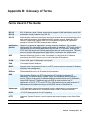
Appendix B: Glossary of Terms . . . . . . . . . . . . . . . . . . . . . .
87
Terms Used in This Guide. . . . . . . . . . . . . . . . . . . . . . . . . . . . . . .
87
4 9600 Series IP Telephones Release 3.1 SP4 Installation and Maintenance Guide
Contents
Appendix C: Related Documentation . . . . . . . . . . . . . . . . . . .
89
IETF Documents . . . . . . . . . . . . . . . . . . . . . . . . . . . . . . . . . .
ITU Documents. . . . . . . . . . . . . . . . . . . . . . . . . . . . . . . . . . .
ISO/IEC, ANSI/IEEE Documents . . . . . . . . . . . . . . . . . . . . . . . . .
89
89
89
. . . . . . . . . . . . . . . . . . . . . . . . . . . . . . . . . .
91
Index
Issue 8 March 2012
5
Contents
6 9600 Series IP Telephones Release 3.1 SP4 Installation and Maintenance Guide
Chapter 1: Introduction
About This Guide
This guide describes how to install and maintain the 9600 Series IP Telephone product line and
troubleshoot telephone problems.
All 9600 Series IP Telephones support the H.323 signaling protocol and work natively as of
Avaya Communication Manager (CM) Release 4.0; when operating under earlier CM releases
the telephones can be aliased as 4600 Series IP Telephone sets as described in the Avaya
®
one-X Deskphone Edition for 9600 Series IP Telephones Administrator Guide.
The 9620, 9630, and 9640 IP Telephones can alternately be configured to use Session Initiation
Protocol (SIP) and require Avaya Communication Manager Release 4.0 or greater. For more
information about SIP configuration, installation, and maintenance for 9600 Series IP
®
Telephones, see the Avaya one-X Deskphone Edition for 9600 Series SIP IP Telephones
Installation and Maintenance Guide.
Note:
Note:
Note:
Unless otherwise indicated, generic references in this document to a call server
can apply to DEFINITY® servers, MultiVantage servers or Avaya Communication
Manager media servers.
Note:
Unless otherwise specified, any reference to HTTP in this guide applies equally
to HTTPS.
Intended Audience
This document is intended for personnel who install and administer the 9600 Series IP
Telephones.
! CAUTION:
CAUTION:
Avaya does not provide product support for many of the products mentioned in
this document. Take care to ensure that there is adequate technical support
available for the servers involved, including, but not necessarily limited to, HTTP,
HTTPS, and DHCP servers. If the servers are not functioning correctly, the IP
telephones might not be able to operate correctly.
Issue 9 January 2013
7
Introduction
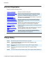
Document Organization
The guide contains the following sections:
Chapter 1: Introduction
Provides an overview of this guide.
Chapter 2: 9600 Series IP
Telephone Installation
Describes the equipment and resources required to properly
install and operate the 9600 Series IP Telephones. Provides
instructions on installing the telephones out of the box.
Chapter 3: Local
Administrative Options
Describes how to set local administrative options, if requested by
the system or LAN administrator.
Chapter 4: Maintaining
9600 Series IP Telephones
Describes maintenance actions like downloading telephone
software from the Avaya support Web site and customizing
system values.
Chapter 5: Troubleshooting
Guidelines
Describes error conditions and messages that might occur
during the installation of the 9600 Series IP Telephones.
Appendix A: Restart
Scenarios
Explains the different scenarios possible for the sequence of the
restart process.
Appendix B: Glossary of
Terms
Provides a glossary of terms used in this document or which are
generally applicable to 9600 Series IP Telephones.
Appendix C: Related
Documentation
Provides references to external documents that relate to
telephony in general, and can provide additional information
about specific aspects of the telephones.
Change History
Issue 1
This document was issued for the first time in July 2006.
Issue 2
This version of the document, revised and issued in September 2006,
supports software Release 1.1.
Issue 3
This version was revised and issued in January, 2007 to support software
Release 1.2.
Issue 4
This version was revised and issued in May, 2007 to support software
Release 1.5.
Issue 5
This version was revised and issued in May, 2008 to support software Release 2.0.
8 9600 Series IP Telephones Administrator Guide Release 3.2
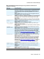
What’s new in Release 3.2
Issue 6
This version was revised and issued in February, 2009 to support 9600 Series IP
Telephone Software Release 3.0 and the addition of three new telephone models:
9620L, 9620C, and 9650C.
Issue 7
This version was revised and issued in November, 2009 to support 9600 Series IP
Telephone Software Release 3.1. In addition to software enhancements, this
version incorporates the 9670G IP Telephone’s installation and maintenance
requirements and information, previously issued separately in May, 2009.
Issue 8
This version was updated and issued in March 2012 to support 9600 Series IP
Telephone Software Release 3.1 Service Pack 4. This Release includes the support
for EAP (TLS) and HAC for regulatory requirements. Support for inclusion of
authentication credentials in BRURI that the telephone can use for authentication.
describes Release 3.1 Service Pack 4 in more detail.
Issue 9
This version of the document is the latest and was issued in January 2013 to
support the Release 3.2. This version includes a fix for for muting deskphone in
shared control, support for option -43,support for use of Identity certificates for
authentication, support for inclusion of authentication details in
BRURI,enhancement that lets you configure the call log details and other minor
fixes.
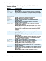
What’s new in Release 3.2
New material in this issue to support Release 3.2 software includes:
●
An enhancement to automatically mute the Speakerphone on 96x0, when it is being used
in Shared Control Mode.
●
Support for Option 43 - that you can use to configure vendor specific options.
●
Support for identity certificates for use in authentication of clients to HTTPS servers.
●
Support for inclusion of authentication credentials in BRURI that the telephone can use for
authentication.
●
Support for a VPN username and password upto 50 characters.
●
Logout option now available on a locked telephone.
●
An enhancement that lets you configure the details that appear on the call log.
●
Support for name as long as 27 characters long in the call log.
●
Enhancement that auto-inserts a (#) pound character at the end of a dial string. This
insertion causes the user to experience that the number has been dialed as soon as the
Call key is pressed.
Issue 9 January 2013
9
Introduction
Online Documentation
See the Avaya support site at http://www.avaya.com/support for 9600 Series IP Telephone
technical and end user documentation.
See Appendix C: Related Documentation for information about accessing non-Avaya
documents, such as those published by the Internet Engineering Task Force (IETF) and the
International Telecommunication Union (ITU).
Customer Support
For 9600 Series IP Telephone support, call the Avaya support number provided to you by your
Avaya representative or Avaya reseller.
Information about Avaya products can be obtained at the following URL:
http://www.avaya.com/support
10 9600 Series IP Telephones Administrator Guide Release 3.2
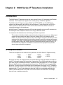
Chapter 2: 9600 Series IP Telephone Installation
Introduction
The 9600 Series IP Telephone product line uses Internet Protocol (IP) technology with Ethernet
interfaces. The IP telephones supplement the existing Avaya IP Solutions platform.
The 9600 Series IP Telephones support DHCP and HTTP/HTTPS over IPv4/UDP which
enhance the administration and servicing of the telephones. These telephones use DHCP to
obtain dynamic IP Addresses and HTTP or HTTPS to download new software versions or
customized settings for the telephones.
All 9600 Series IP Telephones except the 9610 provide the ability to have one IP connection on
the desktop for both a telephone set and a PC using an Ethernet switch.
In compliance with Australian law, the following information is provided:
This equipment shall be installed and maintained by trained service personnel. All the input/
output ports are classified as Safety Extra Low Voltage (SELV, in the meaning of IEC
60950). To maintain safety compliance when connecting the equipment electrically to other
equipment, the interconnecting circuits shall be selected to provide continued conformance
of clause 2.3 for SELV circuits (generally, double/reinforced insulation to 240Vac rms to any
primary/mains circuitry and 120Vac rms to any telecommunications network circuitry). To
ensure that these conditions are adhered to, interconnect the equipment only with the
already approved/certified equipment.
IP Telephone Models
There are ten telephone set models currently defined in the 9600 Series IP Telephone family:
●
●
●
9610
9620
9620L
●
●
●
9620C
9630
9630G
●
●
●
9640
9640G
9650
●
●
9650C
9670G
Except for the 9610, the telephones have an internal Ethernet switch that allows the telephone
and a PC to share the same LAN connection, if appropriate. Thus, 9600 models do not need, or
work with, the 30A switched hub interface. Telephone models appended with "G" have a gigabit
Ethernet (GigE) interface, which speeds data transmission. The 9670G also has an integrated
®
Bluetooth™ interface; setup of a Bluetooth device is described in the Avaya one-X Deskphone
Edition for 9670G IP Telephone User Guide (Document Number 16-602638). Telephone models
appended with "C" have a color display, as does the 9640 but are otherwise essentially the
same as the standard model. The 9620L is a low-cost version of the 9620 that, for example,
does not have an adapter connection.
Issue 9 January 2013
11
9600 Series IP Telephone Installation
Note:
Note:
Unless otherwise stated in this document, any text referring to a telephone with
no suffix, for example the 9620, also refers to all versions of that telephone,
This document describes the installation of these telephones and post-installation maintenance
issues. For details about using the features provided by the telephones, see the user
documentation for each telephone. For information about desk or wall mounting any of the 9600
Series IP Telephones, see the instructions boxed with the telephone. Wall or desk mount
instructions are also available on the Avaya support Web site http://www.avaya.com/support.
Software
As shipped from the factory, the 9600 Series IP Telephone may not contain the most up-to-date
software for registration and operation. When the telephone is first plugged in, a software
download from an HTTP server might be initiated. The software download gives the telephone
upgraded functionality.
For subsequent downloads of software upgrades, the Avaya Media Server provides the
capability for a remote restart of the IP telephone. As a consequence of restarting, the
telephone automatically starts reboot procedures which result in a download if new software is
available. Chapter 4: Maintaining 9600 Series IP Telephones covers downloading new software
releases.
Note:
Note:
The 9670G IP Telephone has a different binary file than other 9600 Series
IPTelephones, as described in the note in Downloading Software Upgrades on
page 53.
Pre-Installation Checklist
Before plugging in the 9600 Series IP Telephone, verify that all the following requirements are
met. Failure to do so prevents the telephone from working properly and can have a negative
impact on the network. Print copies of this checklist for each server and IP telephone.
Verify These Network Requirements
1. Ensure that the LAN uses Ethernet Category 5e cabling running the IPv4 version of Internet
Protocol.
12 9600 Series IP Telephones Administrator Guide Release 3.2
Pre-Installation Checklist
Verify These Network Requirements (continued)
2. Avaya supports 9600 Series IP Telephones running Software Release 3.0 only on Avaya
Communication Manager (CM) 3.1 and later switches. CM Release 3.1 software supports
9600 Series IP Telephones only when aliased as 4600 Series IP Telephones. Specifically,
the 9610 and 9620 have to be aliased as a 4610SW and the 9630/9630G, 9640/9640G, and
9650/9650C have to be aliased as a 4620SW. Avaya Communication Manager Releases
4.0 and greater software provide native support for all 9600 Series IP Telephones,
eliminating the requirement to alias 9600 IP Telephones.
3. The following circuit packs are installed on the switch:
● TN2602 or TN2302IP Media Processor circuit pack. Sites with a TN2302 IP Media
Processor circuit pack are strongly encouraged to install a TN2602 circuit pack to
benefit from increased capacity.
● TN799B, C, or D Control-LAN (C-LAN) circuit pack.
!
Important:
IP telephone firmware Release 1.0 or greater requires TN799C V3 or
greater C-LAN circuit pack(s). For more information, see the Communication
Manager Software and Firmware Compatibility Matrix on the Avaya support
Web site http://www.avaya.com/support.
®
4. The Avaya Media Server is configured correctly, as described in the Avaya one-X
Deskphone Edition for 9600 Series IP Telephones Administrator Guide and Avaya
Communication Manager documentation. Both documents are available at:
http://www.avaya.com/support.
®
5. The DHCP server and application are administered as described in the Avaya one-X
Deskphone Edition for 9600 Series IP Telephones Administrator Guide.
®
6. The HTTP server and application are administered as described in the Avaya one-X
Deskphone Edition for 9600 Series IP Telephones Administrator Guide.
7. The upgrade script and application files from the Avaya Support Web site,
http://www.avaya.com/support, are loaded correctly on the HTTP/HTTPS server.
®
8. If applicable, the DNS server is administered as described in the Avaya one-X Deskphone
Edition for 9600 Series IP Telephones Administrator Guide.
®
9. If applicable, the WML server is administered as described in the Avaya one-X Deskphone
Edition for 9600 Series IP Telephones Administrator Guide.
Notes:
- Any or all of the server applications mentioned in items 5.-9. can be co-resident on the same
hardware, subject to the specific restrictions of each individual application.
®
- See the Avaya one-X Deskphone Edition for 9600 Series IP Telephones Administrator Guide
for more information about:
● administering other network equipment,
● administering applications like firewalls, and
● information about topics like port utilization.
Requirements to Verify for Each IP Telephone
10. You have an extension number and an Avaya Communication Manager security code
(password) for each applicable IP telephone. If your call server supports unnamed
registration, and the telephone settings file allows unnamed registration, you do not need
to provide an extension or password for the telephone. However, if you do not provide an
extension or password, the telephone will have very limited telephone functionality.
(For information, see Unnamed Registration on page 27.)
11. A Category 5e LAN jack is available at each telephone site.
Important:
Note:
Issue 9 January 2013
13
9600 Series IP Telephone Installation
12.
13.
14.
Note:
Electrical power may be provided to each telephone by a Telephone Power Module (which
must be ordered separately). If the LAN will supply IEEE-standard power (Power over
Ethernet) to the telephone, no power module is required.
1 Category 5e modular line cord is available for the connection between the IP telephone
and the PC, if applicable.
Verify that the 9600 Series IP Telephone package includes the following components:
● 1 telephone set with pre-attached stand.
● 1 handset capable of transmitting and receiving 7KHz audio.
● 1 H4DU 9-foot long (when extended) 4-conductor coiled handset cord, plugged into the
telephone and the handset.
● 1 Category 5 modular line cord for the connection from the IP telephone to the Ethernet
wall jack.
● 9630G/9640G Models (only) also include 1 DC power cord with a barrel connector for
use with the 1151
® auxiliary power supply.
● Avaya one-X
® Deskphone Edition for 9600 Series IP Telephones Safety Instructions.
● Avaya one-X
® Deskphone Edition for 9600 Series IP Telephones Stand Instructions.
● Avaya one-X
Deskphone Edition for 9600 Series IP Telephones Wall Mount
Instructions.
Note:
For sites using headsets, the 9600 Series IP Telephones support only the HIS
headset cords. See your Avaya representative for information.
Assembling the 9600 Series IP Telephone
! CAUTION:
CAUTION:
Be careful to use the correct jack when plugging in the telephone. The jacks are
located on the back of the telephone housing and are flanked by icons to
represent their correct use.
Powering the 9600 Series IP Telephone
All 9600 Series IP Telephones can be locally powered with a Telephone Power Module (DC
power jack), available separately. In addition, all 9600 Series IP Telephones support IEEE
802.3af-standard LAN-based power. Before installing a 9600 Series IP Telephone, verify with
the LAN administrator whether the LAN supports IEEE 802.3af, and if so, whether the
telephone should be powered locally or by means of the LAN.
When you add devices like multiple button modules or a Bluetooth™ adapter to applicable 9600
Series IP Telephones, the power class may change. Table 1 shows the effect of such additions
on the power class. For Power Class 2, set the switch labeled IEEE to L. For Power Class 3, set
the switch labeled IEEE to H.
14 9600 Series IP Telephones Administrator Guide Release 3.2
Assembling the 9600 Series IP Telephone
Note:
Note:
The 9610 and 9620L are PoE Class 1 devices and do not have an IEEE power
switch.
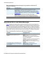
Table 1: Impact of Additional Devices on Telephone Power over Ethernet Power Class
Telephone
Model
9620
9620C
9630
9640
9650
9650C
9630G
(A)
Combinations Resulting in Power
Class 2
●
●
●
●
●
●
●
●
9640G
●
●
Note:
Telephone only
Telephone + Bluetooth adapter
(B)
Combinations Resulting in Power
Class 3
Any combination of
telephone and attachments
not covered in column (A).
Note: the 9620/9620C does not
support SBM24 Button Modules.
Telephone only
Telephone + one SBM24
Telephone + Bluetooth adapter
Any combination of
telephone and attachments
not covered in column (A).
Telephone only
Telephone + Bluetooth adapter
Any combination of telephone
and attachments not covered in
column (A).
Telephone only
Telephone + one SBM24
Telephone + Bluetooth adapter
Any combination of
telephone and attachments
not covered in column (A).
Note:
As of Software Release 3.0, the USB interface supports USB Login and using
digital pictures from a USB device as a screensaver. As of Software Release 2.0,
the USB interface supports importing/exporting contact lists on 9620, 9630, 9640,
and 9650 IP Telephones via a Flash drive. The only exceptions are the 9610 and
9620L models, which do not have a USB jack. Since the power consumption of
the drive will vary from product to product, it is not possible to state what its
impact on PoE power class will be. When the drive attempts to register with the
telephone, the telephone will determine if its current power class setting is
adequate to support the drive. If power is adequate, the telephone will let the
drive register. If it is not adequate, the telephone will prompt the user to change
the power class to Class 3 by changing the IEEE power switch setting from “L” to
Issue 9 January 2013
15
9600 Series IP Telephone Installation
“H.” In extreme situations, the total power consumption with the addition of a USB
device may be greater than what the Class 3 power source can provide. In that
case, the telephone detects this and instructs the user to use an Auxiliary power
supply or to temporarily disconnect one or more of the modules while the USB
device is in use.
The system parameter USBPOWER determines for which power class(es) to
®
enable power to the USB interface; see Chapter 7 in the Avaya one-X
Deskphone Edition for 9600 Series IP Telephones Administrator Guide for
information.
!
Important:
Important:
The last step in assembling the 9600 Series IP Telephone must be applying
power with any modules and/or adapters (and excluding USB devices, headsets,
etc.). Apply power either by plugging the power cord into the power source (local
powering) or plugging the modular line cord into the Ethernet wall jack (IEEE
powering).
! CAUTION:
Failure to connect the proper cables with the proper jacks might result in an
outage in part of your network.
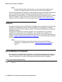
Figures 1 through 4 provide illustrations to connect cords to jacks on 9600 IP Series
Telephones. Use the illustrations and associated procedures as appropriate for telephone
assembly.
CAUTION:
Telephone Model:
9610
9620L
9620, 9620C
9630, 9640, 9650,
9650C
9630G, 9640G,9670G
Note:
See:
Figure 1
Figure 2
Figure 3
Figure 4
Figure 5
Note:
Some 9600 Series IP Telephone models, for example the 9640, accommodate an
external GigE (Gigabit Ethernet) adapter and/or a Bluetooth adapter. Installation
options for those devices are not shown in the illustrations that follow, but are
boxed with the device and are also available on the Avaya support Web site.
16 9600 Series IP Telephones Administrator Guide Release 3.2
Assembling the 9600 Series IP Telephone
Figure 1: Connection Jacks on a 9610 IP Telephone
Issue 9 January 2013
17
9600 Series IP Telephone Installation
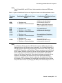
Figure 2: Connection Jacks on a 9620L IP Telephone
MOD
18 9600 Series IP Telephones Administrator Guide Release 3.2
Assembling the 9600 Series IP Telephone
Figure 3: Connection Jacks on a 9620 or 9620C IP Telephone
MOD
L
H
IEEE
Issue 9 January 2013
19
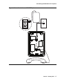
9600 Series IP Telephone Installation
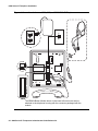
Figure 4: Connection Jacks on a 9630, 9640, or 9650/9650C IP Telephone
MOD
L
H
IEEE
Note:
Note:
The SBM24 Button Module shown in the lower left corner can also be
attached to the telephone housing with the connector packaged with the
module.
20 9600 Series IP Telephones Administrator Guide Release 3.2
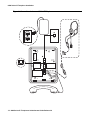
Assembling the 9600 Series IP Telephone
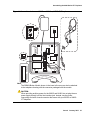
Figure 5: Connection Jacks on a 9630G or 9640G or, 9670G IP Telephone
MOD
L
H
IEEE
Note:
Note:
The SBM24 Button Module shown in the lower left corner can also be attached
to the telephone housing with the connector packaged with the module.
! CAUTION:
CAUTION:
When providing auxiliary power for the 9630G and 9640G, do not plug the aux
power supply directly into the line interface jack. Instead, use the power
connecting cord with a barrel connector that came with your 9630G or 9640G
IP Telephone.
Issue 9 January 2013
21
9600 Series IP Telephone Installation
1. Plug one end of the H4DU 4-conductor coiled handset cord into the telephone and the other
end into the handset.
2. Plug one end of the first Category 5 modular line cord into the Ethernet jack of the PC and
the other end into the secondary Ethernet jack on the 9600 Series IP Telephone,
if appropriate.
3. If the telephone is to be IEEE-powered, plug one end of the second Category 5 modular
line cord into the Ethernet jack on the 9600 Series IP Telephone. Plug the other end of this
cord into the Ethernet wall jack. You are now finished. Do not proceed to Steps 4 or 5.
4. If the telephone is not a Gigabit Ethernet (GigE) telephone (for example, not a 9630G
or 9640G or 9670G) and is to be powered locally, connect one end of the second
Category 5 modular line cord into the Ethernet jack on the 9600 Series IP Telephone. Plug
the other end of this cord into the 1151 power brick jack labeled Phone. Plug another
Category 5 cable into the 1151 power brick jack labeled Line. Plug the other end of this
cable into the Ethernet wall jack. Finally, connect the 1151 to an AC power source. You are
now finished. Do not proceed to Step 5.
5. If the telephone is a GigE telephone (for example, a 9630G or a 9640G or a 9670G) and
is to be powered locally, connect one end of the second Category 5 modular line cord into
the Ethernet jack on the 9600 Series IP Telephone. Plug the other end of this cord into the
Ethernet wall jack. Plug the DC power cord provided with the Gigabit Ethernet telephone
into the 1151 power brick jack labeled Phone. Plug the other end of this cord into the
barrel-shaped jack on the telephone. Finally, connect the 1151 to an AC power source. Note
that with this powering arrangement, there is no connection to the 1151 power brick jack
that is labeled Line.
Note:
Note:
The DC power cord with barrel connector for 1151 auxiliary power use must be
ordered separately for the 9670G IP Telephone.
Dynamic Addressing Process
Note:
Note:
Before starting this process you must have an extension number for the IP
telephone and the Avaya Communication Manager security code (password) for
that extension, unless the telephone will use unnamed registration. For more
information, see Unnamed Registration on page 27.
Any reference to the HTTP server applies equally to an HTTPS server.
Due to a smaller display area messages the 9610 IP Telephone displays may be
truncated or slightly different than those shown here.
22 9600 Series IP Telephones Administrator Guide Release 3.2
Dynamic Addressing Process
The following description of the process of installing the IP telephones assumes that the
process is executed successfully. Only an initial out of the box installation is described. For
errors that might be encountered during the process and the messages displayed, see
Chapter 5: Troubleshooting Guidelines.
When you plug the IP telephone set into the Ethernet wall jack and apply power, if applicable,
the following process takes place.
Note:
Note:
If the application has already been downloaded, the whole process takes
approximately 1 to 2 minutes after the telephone is plugged in. For software
upgrades, including the boot file and application file download, the process might
take 5 - 10 minutes. The duration is based on LAN loading, how many telephones
are being installed at once, and similar factors.
Do not unplug the power cord during the download process.
1. During hardware initialization, the system initialization values NVCONTRAST and
®
NVBRIGHTNESS are checked for non-null values, and set accordingly. The Avaya one-X
name and logo display on sets with bit-mapped displays.
2. The system initialization value for NVLANGFILE is checked for a non-null value, in which
case the text strings in the language file named by that value are used for text display.
Otherwise, English text strings are displayed.
3. The boot code checks for a primary software code image, loads it into volatile memory,
displays the name, and transfers control to it. If a primary software code image is not found,
the boot code loads, displays the name of, and transfers control to the backup software
code image.
4. The telephone activates the Ethernet line interface, the PC Ethernet jack, and dial pad input
to allow the invocation of procedures. The activation occurs as soon as possible after
power-up or a reset.
The telephone displays the speed of the Ethernet interface in Mbps, that is,
10, 100, or 1000. The message No Ethernet * to program displays until the software
determines whether the interface is 10 Mbps, 100 Mbps, or 1000Mbps.
Note:
Note:
The Ethernet speed indicated is the LAN interface speed for both the telephone
and any attached PC, assuming the administrator has not disabled the latter
interface by a PHY2STAT setting.
Issue 9 January 2013
23
9600 Series IP Telephone Installation
!
Important:
Important:
As of Software Release 1.5, pressing * (asterisk) whenever a “* to program“
message displays or whenever the initialization process can support an interrupt
invokes the Craft Access entry procedure to allow manual settings, but only if the
PROCSTAT (local dialpad procedure status) system value is “0.” The zero
PROCSTAT value provides full access to local procedures. If PROCSTAT is “1”
the Craft Access entry procedure can be invoked only when a “* to program“
message displays and then only the VIEW procedure is available. For
information, see Chapter 3: Local Administrative Options.
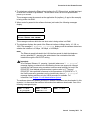
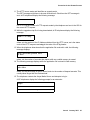
5. The IP telephone sends a request to the DHCP server and invokes the DHCP process.
One of the following messages display:
DHCP: s secs
* to program
DHCP: s secs
VLAN ID = n
DHCP: s secs
where s is the number of seconds that have elapsed since DHCP was invoked. The
message on the left appears if 802.1Q tagging is off and access to local programming
procedures is not disabled or restricted. (See Chapter 3: Local Administrative Options for
specifics.) The middle message appears if 802.1Q tagging is on and access to local
programming procedures is disabled or restricted. If the left and middle messages alternate
every two seconds, 802.1Q tagging is on. When both messages alternate, access to local
programming procedures is not disabled or restricted. Finally, the message on the right
appears if 802.1Q tagging is off and access to local programming procedures is disabled or
restricted.
6. The DHCP server provides IP Addresses for the following hardware:
●
The IP telephone
●
The HTTP/HTTPS server
●
The TN799C or D Control-LAN (C-LAN) circuit pack on the media server
7. Using the list of gateway IP Addresses provided by the DHCP server, the telephone
performs a router check. The telephone cycles through the gateway IP Addresses with
ARPs or pings until it receives a response. When the router is located, received LLDP TLVs
are processed. Then the HTTP process starts.
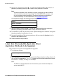
8. While the IP telephone connects to the HTTP server, the telephone displays one of the
following messages:
HTTP:n ipadd
HTTP:n ipadd
* to program
where n is the number of the IP Address obtained from the HTTP server and ipadd is the IP
Address.
24 9600 Series IP Telephones Administrator Guide Release 3.2
Dynamic Addressing Process
!
Important:
Important:
Pressing * at this time invokes the Craft Access entry procedure to allow manual
settings. For information, see Chapter 3: Local Administrative Options.
9. When connected, the telephone looks for an upgrade script file.
10. The HTTP server sends and identifies an upgrade script.
The GET message might have to be sent several times. Each time the GET message is
sent, all IP telephones display the following message:
HTTP: n uri
For HTTP, n is the number of HTTP requests made by the telephone and uri is the URI for
the current HTTP request.
11. While the upgrade script file is being downloaded, all IP telephones display the following
message:
HTTP:n sc etag
where n is the number of the IP Address obtained from the HTTP server, sc is the status
code of the HTTP response and etag is the value of the ETag header.
12. When the telephone determines that the application file received is valid, the following
message displays:
File Obtained;please wait...
s secs
where s is the number of seconds that elapse while non-volatile memory is erased.
13. While the application file is saved in flash memory, all IP telephones display the following
message:
Saving to flash
1% 1 secs
with the percentage of the file and the number of elapsed seconds incremented as the
application file is stored in flash memory.
14. The telephone contacts the Avaya Media Server and attempts to log in.
All IP telephones display a version of the following prompts for an extension:
Login
Issue 9 January 2013
25
9600 Series IP Telephone Installation
Enter Extension
Enter Extension and press Enter or OK
26 9600 Series IP Telephones Administrator Guide Release 3.2
Unnamed Registration
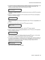
15. Enter a new extension and press OK. To register the telephone without the extension or
password (unnamed), press only OK or make no entry and wait 60 seconds.
Note:
Unnamed registration is the capability to register a telephone with the call server
without entry of an extension or password. The UNNAMEDSTAT parameter must
be set to enable unnamed registration. Telephones registered unnamed have
limited functionality. For more information, see Unnamed Registration.
Note:
All IP telephones display a version of the following prompts for a password:
Login
Enter Password
Enter Password and press Enter or OK
16. Enter the password and press OK. To register the telephone without the extension or
password (unnamed), press OK or make no entry and wait 60 seconds.
17. The extension is visible as you enter it but the password displays as asterisks. The system
determines whether the extension is in use.
18. Successful completion of this process produces a dial tone when the Speaker button is
pressed or the handset is lifted.
The IP telephone was installed successfully.
Unnamed Registration
Unnamed registration is a capability an IP telephone can have to register with a call server, and
receive limited service, without requiring an extension and password entry. Typical
environments where this functionality is useful include:
●
“Hot-desking” environments where there is a period of time between one user logging out
and another user logging in on the same telephone.
●
Using the Avaya Softphone application in “road warrior” mode, which allows a traveller to
invoke the telephony features and functionality by taking over the office telephone
extension. This takeover unregisters the office telephone.
In both examples, the user unregisters the telephone by logging off or by taking the office
telephone extension over to another telephone. Without unnamed registration, the telephone in
the first example will just wait for an extension and password entry and the telephone in the
second example will continue attempting to register at regular intervals. The downside of a
telephone being unregistered is that no one can use the telephone, for example, to report a
building emergency like a fire.
Issue 9 January 2013
27
9600 Series IP Telephone Installation
Unnamed registration allows the telephone to register without an extension and password.
Because there is no extension, telephony functionality is limited, specifically:
●
The user has only one call appearance, and hence, cannot transfer or conference calls.
●
The user has no administered feature buttons, and cannot invoke on-hook dialing.
●
Extension-based information, like a given user’s Contacts data or Option settings are not
available.
●
The user is limited to the calling capability administered for PSA (Personal Station Access)
on the call server, for example, access to an emergency number.
●
The telephone cannot receive any outside calls.
Unless otherwise disabled, the telephone automatically attempts to register unnamed if no
action is taken on the telephone Extension entry screen within 60 seconds. Initiating any ID or
password entry disables and prevents unnamed registration from occurring. Unnamed
registration is ignored after any dialpad entry.
Administrators can disable unnamed registration by appropriately administering the system
®
parameter UNNAMEDSTAT, as indicated in Chapter 7 of the Avaya one-X Deskphone Edition
for 9600 Series IP Telephones Administrator Guide. Unnamed registration appears to the end
user like Avaya Communication Manager TTI Mode, and is similar from an administration
perspective. For more information about TTI, see your Avaya Communication Manager
documentation.
28 9600 Series IP Telephones Administrator Guide Release 3.2
Chapter 3: Local Administrative Options
Introduction
During installation or after you have successfully installed an IP telephone, you might be
instructed to administer one of the manual procedures described in this chapter. These local
administrative procedures are also referred to as Craft Procedures.
There are two forms of Local Administrative Options. One allows access to all the capabilities
and functionality described in this chapter while the other allows access only to an administrable
level of VPN capabilities and functionality. The VPN-specific option allows the administrator to
grant VPN users access to the VPN procedure itself, while preventing these users from
accessing any other Local Administrative Procedure. The administrator may grant the VPN user
permission to change VPN settings or only to view them. For more information on access to
VPN-only Local Administrative Options, see the VPN Setup Guide for 9600 Series IP
Telephones (Document 16-602968).
Note:
Note:
You can modify the settings file to set parameters for IP telephones that
download their upgrade script and application files from the same HTTP server.
See Chapter 4: Maintaining 9600 Series IP Telephones and “9600 Series IP
®
Telephone Scripts and Application Files” in Chapter 4 of the Avaya one-X
Deskphone Edition for 9600 Series IP Telephones Administrator Guide.
! CAUTION:
CAUTION:
Only trained installers or technicians should perform local (craft) procedures.
Perform these procedures only if instructed to do so by the system or LAN
administrator.
Static administration of these options causes upgrades to work differently than if
they are administered dynamically. Values assigned to options in static
administration are not changed by upgrade scripts. These values remain stored
in the telephone until either:
- a new boot file is downloaded, or
- the IP telephone is reset, as indicated in Reset System Values on page 47.
Use these option-setting procedures only with static addressing and, as always, only
if instructed by the system or LAN administrator. Do not use these option-setting
procedures if you are using DHCP. DHCP is the Dynamic Addressing Process, as
indicated in Dynamic Addressing Process on page 22.
Issue 9 January 2013
29
Local Administrative Options
Accessing Local (Craft) Procedures
Note:
Note:
In addition to the procedures listed here, the administrator may allow access to
only the VPN procedure, by setting the VPNPSWD parameter in the settings file.
For more information on access to VPN-only Local Administrative Options, see
the VPN Setup Guide for 9600 Series IP Telephones (Document 16-602968).
As of Release 1.5, when PROCSTAT is "0" (full access to local Craft procedures) you can
invoke local craft procedures during initialization whenever this message displays:
* to program
or at any other time the initialization process can support a processing interrupt. If PROCSTAT
is set to "1" (access allowed only to the VIEW craft procedure for debugging purposes), you can
invoke local Craft procedures only when the "* to program" message displays during
initialization.
Note:
Note:
The “* to program” message is supported even if the value of PROCSTAT is
“1” when the messages “Address conflict,” “Subnet conflict,” “Bad
router?” and “Bad FileSv address” display. Allowing Craft procedure
access in response to these messages prevents situations in which input is
required but not allowed.
For earlier software releases, PROCSTAT must be zero to invoke craft access (Release 1.2).
For Releases 1.0 and 1.1, PROCSTAT must be equal to “0” plus PROCPSWD must be null.
Note:
Note:
The factory-set default Craft Access Code (PROCPSWD) is 27238.
During Telephone Startup:
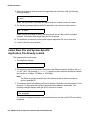
1. During startup, invoke local procedures by pressing * to display the Craft Access Code
Entry screen:
Enter code:__
#=OK
2. Enter the local dialpad procedure password (0 to 7 numeric digits), as specified by the
system administrator in the system value PROCPSWD. For security purposes, the
telephone displays an asterisk for each numeric dialpad press. If you are using a 9670G IP
Telephone, and need to backspace during password entry, use the Contacts button; for
other 9600 Series phones, use the left arrow button or the designated softkey.
30 9600 Series IP Telephones Administrator Guide Release 3.2
Accessing Local (Craft) Procedures
3. Press # when password entry is complete.
The entry is compared to the PROCPSWD value. If they match, the telephone displays the
Craft Local Procedure screen, "Select procedure and press Start."
4. For all 9600 Series IP Telephones except the 9670G, use the navigation arrows to scroll to
and highlight the local procedure you want, then press Start or OK. Or scroll to the
procedure you want and press the corresponding line button. For the 9670G IP Telephone,
scroll to the local procedure you want if it not already displayed; touch that line on which the
local procedure you want appears.
During Normal Telephone Operation (all 9600 IP Telephones except the 9610):
1. Invoke all local procedures by pressing the Mute button, entering the local (dialpad)
procedure password (0 to 7 numeric digits), then pressing the # button. If you are using a
9670G IP Telephone and need to backspace during password entry, use the Contacts
button; for other 9600 Series phones, use the left arrow button or the designated softkey.
A 6-second timeout is in effect between button presses after pressing the Mute button. If
you do not press a valid button within 6 seconds of pressing the previous button, the
collected digits are discarded. In this case, no administrative option is invoked.
The entry is compared to the PROCPSWD value. If they match, the telephone displays the
Craft Local Procedure screen, and prompts "Select procedure and press Start.
2. For 9600 Series IP Telephones except the 9670G, use the navigation arrows to scroll to and
highlight the local procedure you want, then press Start or OK. Or scroll to the procedure
you want and press the corresponding line button. For the 9670G IP Telephone, scroll to the
local procedure you want if it not already displayed; touch that line on which the local
procedure you want appears.
During Normal Telephone Operation (9610 IP Telephone only):
1. Invoke all local procedures by displaying the Contacts application and pressing the
Contacts button.
Note:
Note:
If the Contacts application is not displayed, press the Contacts button twice and
proceed to the next step.
2. Enter the local (dialpad) procedure password (PROCPSWD, 0 to 7 numeric digits), then
press the # button.
Note:
Note:
A 6-second timeout is in effect between button presses after pressing the
Contacts button. If you do not press a valid button within 6 seconds of pressing
the previous button, the collected digits are discarded. In this case, no
administrative option is invoked.
The entry is compared to the PROCPSWD value. If they match, the telephone displays
the Craft Local Procedure screen and prompts "Select procedure and press Start."
Issue 9 January 2013
31
Local Administrative Options
3. Use the navigation arrows to scroll to and highlight the local procedure you want, then press
Start or OK. Or scroll to the procedure you want and press the corresponding line button.
32 9600 Series IP Telephones Administrator Guide Release 3.2
Entering Data for Administrative Options
Entering Data for Administrative Options
This section applies to all 9600 Series IP Telephones and describes how to enter data for
administrative options.
1. The first application line on any screen is automatically highlighted (selected) when the
telephone displays the screen. To select the item on that line, press the appropriate softkey
at the bottom of the screen, for example, Change or Save, or the OK button. To select a
different line, use the down or up navigation arrows to change the line focus. When the
desired line is highlighted, then press a softkey or OK to select that line.
2. Attempts to enter invalid data are rejected and the telephone emits an error beep.
3. If you enter a numeric digit that causes the IP Address or subnet mask value to exceed 255,
or any value to exceed its maximum field value, an error beep tone sounds, the digit is
ignored, and the cursor does not move forward.
4. If you enter a numeric digit for a value or for an IP Address or subnet mask field after
entering only a zero, the new digit replaces the zero.
5. To backspace on all phones except the 9670, press the leftmost softkey; for the 9670, use
the Bksp softkey instead. When you press the applicable button or key to backspace, the
most recently entered digit or period is erased from the display. The cursor remains in the
erased character’s former position.
6. Pressing Exit (or touching the softkey for the 9670G) exits the local procedures. If any
changes were made using the ADDR procedure or if the Crafts Entry screen was invoked
during startup, the telephone immediately resets. If no ADDR changes were made or if the
local procedures were invoked post-startup, the telephone redisplays the screen (or other
display) that was effective when the craft options was invoked.
Note:
Note:
Note:
If PROCSTAT has been administered to 1, you will not be able to invoke any
administrative options other than V I E W.
Note:
The 9670G presents an onscreen keyboard that allows you to "type" the data you
®
want to enter on the display. See the Avaya one-X Deskphone Edition for
9670G IP Telephone User Guide for information on using the onscreen keyboard.
Issue 9 January 2013
33
Local Administrative Options
About Local Administrative Procedures
Craft procedures allow you to customize the 9600 Series IP Telephone installation for your
specific operating environment. This section provides a description of each local administrative
option covered in this guide, with references to the pages on which the option appears.
Note:
Note:
Due to its smaller display size, the 9610 IP Telephone does not present the
procedures exactly as shown in this chapter. The 9610 does display essential
information like the other 9600 Series IP Telephones, but that information may be
formatted differently. Likewise, the 9670G is touch screen-based, therefore
simply "touching" a line or a softkey produces the same result as selecting a line
or a softkey on other 9600 Series IP Telephones.
Unless otherwise prohibited using administration, a user can view but not change
most of the parameters associated with Craft procedures. For more information,
see the applicable users guide(s).
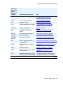
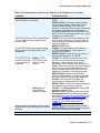
Shown As
(this value
always
displays in
English)
Craft Procedure Purpose
See
8021X
Set 802.1X operational mode
Set the 802.1X Operational Mode on
page 36.
ADDR
Address information
programming
Static Addressing Installation on
page 37.
AGC
Enable/disable Automatic Gain
Control
Disable/Enable Automatic Gain
Control on page 39.
CALIBRATE
SCREEN
Calibrate the 9670G
touchscreen.
Calibrating the 9670G Touch Screen on
page 40
CHADDR
Set the DHCP chaddr field
value
Manually Setting the DHCP Client
Hardware Address on page 41.
CLEAR
Clear all values to factory
defaults
Clear Procedure on page 41.
CONT
Adjust the contrast of any
SBM24 Button Modules and
any 9600 Series IP Telephones
other than the 9620C, 9640, or
9650C
Adjusting Contrast on SBM24 Button
Modules and Non-Color IP
Telephones on page 42.
1 of 2
34 9600 Series IP Telephones Administrator Guide Release 3.2
About Local Administrative Procedures
Shown As
(this value
always
displays in
English)
Craft Procedure Purpose
See
DEBUG
Enable/disable Debug Mode
Disable/Enable Debug Mode on
page 43.
GROUP
Set the Group Identifier
Group Identifier on page 43.
INT
Interface Control
Interface Control on page 44.
LOG
Enable/disable Event Logging
Disable/Enable Event Logging on
page 45.
LOGOUT
Log off the telephone
Logoff on page 46.
MLS
View Multi-Language text
Strings
View Multi-Language Strings on
page 47.
RESET
VALUES
Reset system initialization
values to defaults
Reset System Values on page 47.
RESTART
PHONE
Restart the telephone
Restart the Telephone on page 48.
SIG
Set the signaling protocol
download flag
Signaling Protocol Identifier on page 49.
SSON
Set the Site-Specific Option
Number
Site-Specific Option Number Setting on
page 50.
TEST
Initiate a self-test
Self-Test Procedure on page 50.
VIEW
View current parameter values
and file names
The View Administrative Option on
page 60.
VPN
Administer and/or view Virtual
Private Network (VPN) settings
VPN Setup Guide for 9600 Series IP
Telephones (Document 16-602968).
2 of 2
Issue 9 January 2013
35
Local Administrative Options
Set the 802.1X Operational Mode
Use the following procedure to set or change the operational mode.
Note:
Note:
When updating local (Craft) procedures from a 9670G IP Telephone, touching the
line you want to change or the applicable softkey produces the same result as
selecting a line and pressing the applicable softkey on other 9600 Series IP
Telephones.
1. When you select 802.1X from the Craft Local Procedure Screen, the following text displays:
Supplicant:
Pass-thru:
where the Supplicant line is the text string associated with the current system value of
DOTIXSTAT (802.1X Supplicant Mode operation control), defined as:
●
"Disabled" if DOT1XSTAT = 0
●
"Unicast-only" if DOT1XSTAT = 1
●
"Unicast/multicast" if DOT1XSTAT = 2
and the Pass-thru line is a text string associated with the current system value of DOT1X
(802.1X Supplicant Mode)
●
"Enabled mode" if DOT1X = 0
●
"Enabled w/Logoff" if DOT1X = 1
●
"Disabled" if DOT1X = 2
2. Select (highlight) the line you want to change, then press Change.
3. Depending on which line you selected to change, the following text displays:
Current setting:
New Setting:
where, if you selected the Supplicant line, the setting is the text string associated with the
current system value of DOTIXSTAT, or if you selected the Pass-thru line, the setting is the
text string associated with the current system value of DOTIX.
4. To change the setting, press the Right (or Left) navigation arrow to cycle through the
applicable settings.
Depending on the current value, the next sequential text string is selected and displayed as
the New setting. For example when changing the Pass-thru mode, if the current value is
Pass-thru mode, pressing the Choice Selector displays P-t w/Logoff. If the current setting is
disabled, pressing the Choice Indicator changes the new setting to Pass-thru mode.
36 9600 Series IP Telephones Administrator Guide Release 3.2
Pre-Installation Checklist for Static Addressing
5. Press Save to store the new setting and redisplay the Craft Local Procedure screen.
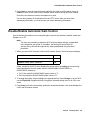
Pre-Installation Checklist for Static Addressing
Before performing static programming of address information, verify that all the requirements
listed in the Verify These Network Requirements section of the Pre-Installation Checklist are
met. You do not have to consider item 4. on page 13, as it refers to the DHCP server. In
addition, you must have the values for the following parameters. Failure to do so can cause data
entry errors that prevent the telephone from working. Such errors can also have a negative
impact on your network. Print copies of this checklist for each subnet.
1.
2.
3.
4.
The IP Address of the media server.
The IP Address of the gateway/router.
The IP netmask.
The IP Address of the HTTP server.
Static Addressing Installation
The usual way to assign IP Addresses to IP telephones is the automatic method described in
Dynamic Addressing Process on page 22. There might be times, however, when manual
assignment of IP Addresses is desired.
! CAUTION:
CAUTION:
Static addressing is necessary when a DHCP server is unavailable.
Because of the increased opportunities for text entry errors associated with static
addressing, Avaya strongly recommends that a DHCP server be installed and
static addressing avoided.
Issue 9 January 2013
37
Local Administrative Options
Use the following procedure to invoke manual address information programming.
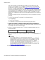
1. When you select ADDR from the Craft Local Procedure Screen, the Static Addressing Local
Procedure screen displays as follows with the prompt “Select address to change.”:
Static Addressing screen
Phone
nnn.nnn.nnn.nnn
Call Server
nnn.nnn.nnn.nnn
Router
nnn.nnn.nnn.nnn
Mask
nnn.nnn.nnn.nnn
File Server
nnn.nnn.nnn.nnn
802.1Q
NVL2Q text string
VLAN ID
dddd
VLAN Test
ddd
Line Description and (System Value)
Telephone IP Address (IPADD)
Call Server in use; media server IP Address
router in use; gateway/router IP Address
IP network mask (NETMASK)
IP Address of HTTP/S File Server in use
NVL2Q setting text description
NVL2QVLAN
NVVLANTEST
where:
●
●
●
nnn.nnn.nnn.nnn is the current IP Address associated with the specific address
information to its left, which could be either a value previously set by a technician, or the
original value of NVIPADD if no previous change was made,
NVL2Q text string is the text string associated with the current system value of NVL2Q
where "Auto" = an NVL2Q value of "0", "On" = an NVL2Q value of "1", and "Off" = an
NVL2Q value of "2", and
dddd is the current value of NVL2QVLAN and ddd is the current value of NVVLANTEST,
respectively.
2. Use the navigation arrows to scroll to and highlight the address you want to change, then
press Change to display the change screen for that specific address value.
3. Depending on the item you selected, choose one of the following:
If you want to
Change any of the IP
Address values (Phone,
Call Server, Router,
Mask, &/or File Server)
Change the 802.1Q
value
Change the VLAN ID
value
Change the VLANTEST
value
Then
Use the dialpad to enter the new IP Address. IP Addresses
have three sets of three digits followed by a period. Pressing *
following entry of three digits causes a period to be placed in
the next position, and the cursor to advance one position to the
right.
For example, to enter the IP Address 111.222.333.444, press
the 1 on the dialpad three times then press *, press the 2 on the
dialpad three times then press *, press the 3 on the dialpad
three times then press *, then press the 4 on the dialpad three
times. Proceed to the next step.
Use the Right navigation arrow to cycle through the text strings
corresponding to the NVL2Q values defined as
“Auto” if NVL2Q=0, “On” if NVL2Q=1, and “Off” if NVL2Q= 2
until the text string of the value you want to change to displays.
Proceed to the next step.
Use the dialpad to enter the new static VLAN ID of from 0 to
4094, inclusive. Proceed to the next step.
Use the dialpad to enter the new value of the DHCPOFFER
wait period of from 0 to 999, inclusive. Proceed to the next step.
38 9600 Series IP Telephones Administrator Guide Release 3.2
Disable/Enable Automatic Gain Control
4. Press Save to store the new setting and redisplay the Craft Local Procedure screen or
Cancel to return to the Craft Local Procedure screen without saving the value entered.
Once the new values are stored, the telephone is reset.
If a new boot program is downloaded from the HTTP server after you enter static
addressing information, you must reenter your static addressing information.
Disable/Enable Automatic Gain Control
Use the following procedure to turn automatic gain control for the handset, headset, and/or the
Speaker on or off.
Note:
Note:
The user can potentially override the AGC local procedure settings, as described
in the telephone user guide. If overridden, the backup file stores the AGC
value(s) set by the user and ignores any setting established using this local
procedure.
1. When you select AGC from the Craft Local Procedure Screen, the following text displays:
Handset Auto Gain Control
On
Headset Auto Gain Control
On
Speaker Auto Gain Control
On
where, except for the 9610 which displays the actual value, the setting is the text string
associated with the current system value of NVAGCHAND, NVAGCHEAD, or
NVAGCSPKR, defined as:
●
"On" if the respective NVAGCXXXX system value is "1".
●
Off if the respective NVAGCXXXX system value is "0".
2. To change the setting, select (highlight) the appropriate line. Press Change or for the 9610,
use the Right/Left navigation arrows to toggle the selected setting from On to Off or vice
versa.
3. Press Save to store the new setting, update the associated system value, and redisplay the
Craft Local Procedure screen.
Issue 9 January 2013
39
Local Administrative Options
Calibrating the 9670G Touch Screen
Screen calibration properly aligns the touch screen but should only be used for a significant
problem with the touch screen.
!
Important:
Note:
Important:
Use a stylus rather than your finger to touch the calibration points precisely.
Note:
The CLEAR Craft procedure clears any calibration data set using the
CALIBRATE SCREEN Craft procedure, but does not affect factory-set calibration
data. Use the Default softkey to restore factory-set calibration. Calibration results
are not saved as part of a backup.
To calibrate the 9670G touch screen, use the following procedure:
1. When you select CALIBRATE SCREEN from the Craft Local Procedure Screen, the
telephone displays three softkeys - Start, Default, and Cancel.
2. Take one of the following actions:
●
Touch Cancel to return to the Craft Local Procedure screen without calibrating the
screen.
●
Touch Default to reset the calibration parameters to the factory-set values, as evidenced
by a confirmation tone and redisplay of the Craft Local Procedure screen.
●
Touch Start to calibrate the screen. A calibration target (+) appears at a particular point
on the screen. Proceed to the next step.
3. Touch the center of the target with the stylus as soon as it appears. The target
disappears, and a new target appears in a different part of the screen.
4. Touch the center of each target with the stylus within 10 seconds of its appearance. After
all four targets have been touched, a confirmation tone sounds and a "Calibration
successful" message displays.
5. Touch Save to return to the Craft Local Procedure screen. Calibration results are stored
in the telephone’s non-volatile memory.
6. Touch Cancel at any time to return to the Craft Local Procedure screen without
completing the touch screen calibration.
40 9600 Series IP Telephones Administrator Guide Release 3.2
Manually Setting the DHCP Client Hardware Address
Manually Setting the DHCP Client Hardware Address
Use this procedure to manually set or change the DHCP Client Hardware Address, if you use
static addressing rather than DHCP.
1. When you select CHADDR from the Craft Local Procedure Screen, the following text
displays:
Current setting:
New Setting:
where, except for the 9610 which displays the actual value, the setting is the current system
value of NVCHADDR.
2. To change the setting, enter a valid client hardware address. This value is usually the MAC
address, which DHCP then converts to an integer preceded by zeroes.
3. Press Save to store the new setting and redisplay the Craft Local Procedure screen.
Clear Procedure
Sometimes, you might want to remove all administered values, user-specified data, and option
settings. Essentially, you want to return a telephone to its initial “clean slate” or out of the box
condition. This is usually done when passing a telephone to a new, dedicated user when the
LOGOFF option is not sufficient. For example, a new user is assigned the same extension, but
requires different permissions than the previous user.
The CLEAR option erases all administered data—static programming, file server and call server
programming, and user settings including Contact button labels and locally programmed
Feature button labels, and restores all such data to default values. The CLEAR option does not
affect the software load itself. If you have upgraded the telephone, the telephone retains the
latest software. Once you have cleared a telephone, you can administer it normally.
! CAUTION:
CAUTION:
This procedure erases all administered data, without any possibility of recovering
the data.
Use the following procedure to clear the telephone of its administrative, user-assigned and
options values.
1. When you select CLEAR from the Craft Local Procedure Screen, the telephone displays the
prompt "Press Clear again to confirm."
Issue 9 January 2013
41
Local Administrative Options
2. If you do not want to clear all values, press Cancel to terminate the procedure and retain
the current values. Press Clear to clear all values to their initial default values.
The telephone displays the following text:
Clearing values...
The telephone is cleared to its “out of the box” state, resetting the following values to their
factory defaults:
●
All system values and system initialization values.
●
802.1X identity and password.
●
User options, parameter settings, identifiers and password.
●
Any user data like Contact Lists or Call Logs are deleted.
After clearing the values, the telephone resets.
Adjusting Contrast on SBM24 Button Modules and
Non-Color IP Telephones
Note:
Note:
When updating local (Craft) procedures from a 9670G IP Telephone, touching the
line you want to change or the applicable softkey produces the same result as
selecting a line and pressing the applicable softkey on other 9600 Series
IPTelephones.
Use the following procedure to adjust the contrast of any SBM24 Button Module when attached
to any 9600 Series IP Telephone or any non-color IP Telephone. (The 9620C, 9640, 9650C, and
the 9670G each have a color display, and contrast adjustment is not applicable.) Fifteen
contrast levels are available.
1. When you select CONT from the Craft Local Procedure Screen, the telephone prompts you
to use the Right and Left navigation arrows to change the SBM24 (shown as Module: 1) or
the telephone (shown as Phone:) contrast.
2. To change the setting, press the Right (or Left) navigation arrow to cycle through the
settings. The factory default setting is the middle setting.
As you press the navigation arrow the next higher or lower contrast level is selected and
displayed as the setting.
3. If more than one SBM24 button module is attached, scroll down to that line, for example, to
Module: 2 and repeat Step 2 to change the contrast.
4. Press Save to store the new contrast setting(s) and redisplay the Craft Local Procedure
screen.
42 9600 Series IP Telephones Administrator Guide Release 3.2
Disable/Enable Debug Mode
Disable/Enable Debug Mode
Note:
Note:
When updating local (Craft) procedures from a 9670G IP Telephone, touching the
line you want to change or the applicable softkey produces the same result as
selecting a line and pressing the applicable softkey on other 9600 Series IP
Telephones.
Use the following procedure to turn the debug mode for the button module serial port on or off.
! CAUTION:
A DEBUG setting of “On” disables any SBM24 Button Module connected to the
module interface or any adapter plugged into Slot 2.
CAUTION:
1. When you select DEBUG from the Craft Local Procedure Screen, the following text
displays:
Debug Mode
On
where, except for the 9610 for which this procedure is not applicable, the setting is the text
string associated with the current system value of NVDEBUG, defined as:
●
"On" if the NVDEBUG system value is "1".
●
"Off" if the NVDEBUG system value is "0".
2. Press Change to toggle the selected setting from On to Off or vice versa.
3. Press Save to store the new setting.
If the value changed from "On" to "Off", the telephone initiates a reset. If the value changed
from "Off" to "On" the Craft Local Procedure screen redisplays.
The telephone saves the new value.
Group Identifier
Note:
Note:
When updating local (Craft) procedures from a 9670G IP Telephone, touching the
line you want to change or the applicable softkey produces the same result as
selecting a line and pressing the applicable softkey on other 9600 Series IP
Telephones.
Issue 9 January 2013
43
Local Administrative Options
Use the following procedure to set or change the Group Identifier.
Note:
Note:
Perform this procedure only if the LAN Administrator instructs you to do so.
For more information about groups, see The GROUP System Value on page 57.
1. When you select GROUP from the Craft Local Procedure Screen, the following text
displays:
Current setting:
New Setting:
where the setting is the current system value of NVGROUP.
2. Enter a valid Group value (0-999).
3. Press Save to store the new setting and redisplay the Craft Local Procedure screen.
Interface Control
Note:
Note:
When updating local (Craft) procedures from a 9670G IP Telephone, touching the
line you want to change or the applicable softkey produces the same result as
selecting a line and pressing the applicable softkey on other 9600 Series IP
Telephones.
Use the following procedure to set or change the interface control value.
1. When you select INT from the Craft Local Procedure Screen, the following text displays with
a prompt to use the Right and Left navigation arrows to select a setting:
Ethernet:
PC Ethernet:
Choice Selector
Choice Selector
Except for the 9610 which displays the actual value, the values shown are the text strings
associated with the current PHY1STAT on the Ethernet line and the current PHY2STAT
system value on the PC Ethernet line.
The PHY1STAT text strings are:
●
"Auto" when PHY1STAT = 1
●
"10Mbps half" when PHY1STAT = 2
●
"10Mbps full" when PHY1STAT = 3
●
"100Mbps half" when PHY1STAT = 4
●
"100Mbps full" when PHY1STAT = 5
44 9600 Series IP Telephones Administrator Guide Release 3.2
Disable/Enable Event Logging
●
"1000 Mbps full" when PHY1STAT = 6
The PHY2STAT text strings are:
●
"Disabled" when PHY2STAT = 0
●
"Auto" when PHY2STAT = 1
●
"10Mbps half" when PHY2STAT = 2
●
"10Mbps full" when PHY2STAT = 3
●
"100Mbps half" when PHY2STAT = 4
●
"100Mbps full" when PHY2STAT = 5
●
"1000 Mbps full" when PHY2STAT = 6
2. To change the Ethernet setting, press the Right navigation arrow to cycle through the
possible settings.
Depending on the current value, the next sequential text string is selected and displayed as
the setting. For example, if the current value is 10Mbps half (2), pressing the Right
navigation arrow changes the value to 10Mbps full (3). If the current value is 1000Mbps full
(6), pressing the Right navigation arrow changes the value to Auto (1).
3. To change the PC Ethernet setting, select that line and press the Right navigation arrow to
cycle through the possible settings.
4. Press Save to store the new setting(s) and redisplay the Craft Local Procedure screen.
Disable/Enable Event Logging
Note:
Note:
When updating local (Craft) procedures from a 9670G IP Telephone, touching the
line you want to change or the applicable softkey produces the same result as
selecting a line and pressing the applicable softkey on other 9600 Series IP
Telephones.
Use the following procedure to enable or disable logging of system events.
1. When you select LOG from the Craft Local Procedure Screen, the telephone prompts you to
use the Right and Left navigation arrows to select a setting and displays the following text:
Log: text string
Choice Selector
where, except for the 9610 which displays the actual value, the text string is the wording
associated with the current system value of NVLOGSTAT, defined as:
●
"Disabled" when NVLOGSTAT = 0
Issue 9 January 2013
45
Local Administrative Options
●
"Emergencies" when NVLOGSTAT = 1
●
"Alerts" when NVLOGSTAT = 2
●
"Critical" when NVLOGSTAT = 3
●
"Errors" when NVLOGSTAT = 4
●
"Warnings" when NVLOGSTAT = 5
●
"Notices" when NVLOGSTAT = 6
●
"Information" when NVLOGSTAT = 7
●
"Debug" when NVLOGSTAT = 8
2. To change the setting, press the Right (or Left) navigation arrow to cycle through the
settings.
Depending on the current value, the next sequential text string is selected and displayed as
the setting. For example, if the current value is Alerts (2), pressing the Right navigation
arrow changes the value to Critical (3). If the current value is Debug (8), pressing the Right
navigation arrow changes the value to Disabled (0).
3. Press Save to store the new setting and redisplay the Craft Local Procedure screen.
Logoff
Use the following procedure to log off a telephone.
Note:
Note:
Note:
If a user registered (logged in) via a USB device, this procedure is not applicable.
The only way to log off a telephone registered with a USB device is by removing
the device.
Note:
When updating local (Craft) procedures from a 9670G IP Telephone, touching the
line you want to change or the applicable softkey produces the same result as
selecting a line and pressing the applicable softkey on other 9600 Series IP
Telephones.
! CAUTION:
CAUTION:
Once a telephone is logged off, a password and extension might be needed to
log back on.
1. When you select LOGOUT from the Craft Local Procedure Screen, the telephone displays
the following text:
Press Log Out again to confirm
46 9600 Series IP Telephones Administrator Guide Release 3.2
View Multi-Language Strings
2. Press Cancel to return to the Craft Local Procedure screen without logging off the
telephone. Press Log Out to unregister the telephone from the call server.
View Multi-Language Strings
Note:
Note:
When updating local (Craft) procedures from a 9670G IP Telephone, touching the
line you want to change or the applicable softkey produces the same result as
selecting a line and pressing the applicable softkey on other 9600 Series IP
Telephones.
Use this procedure to look at the language strings available on the telephone. A language string
is any set of words or phrases on the IP Telephone user interface, in the currently active
language.
1. When you select MLS from the Craft Local Procedure Screen, the following text displays:
Tag # N
Text string for tag #N
text string
where N is the label associated with a specific language in the downloaded language file
and text string is the wording associated with that Tag number.
2. Use the Up and Down navigation arrows to scroll through the list of text strings. Use the
Right and Left navigation arrows to scroll right or left one character at a time to view the
entire text string, if it exceeds the available display line space.
3. Press Back to return to the Craft Local Procedure screen.
Reset System Values
Note:
Note:
When updating local (Craft) procedures from a 9670G IP Telephone, touching the
line you want to change or the applicable softkey produces the same result as
selecting a line and pressing the applicable softkey on other 9600 Series IP
Telephones.
Issue 9 January 2013
47
Local Administrative Options
Use the following procedure to reset all system initialization values to the application software
default values.
! CAUTION:
This procedure erases all static information, without any possibility of recovering
the data.
CAUTION:
1. When you select RESET VALUES from the Craft Local Procedure Screen, the telephone
displays the following text:
Press Reset to confirm.
2. Press Cancel to return to the Craft Local Procedure screen without resetting the telephone.
Press Reset to start the telephone reset.
The telephone resets from the beginning of registration, which might take a few minutes.
A reset:
●
Resets all system values and system initialization values except AUTH and NVAUTH to
default values.
●
Resets the 802.1X ID and Password to their default values.
●
Resets call server values to their defaults.
●
Deletes any entries in the Redial buffer.
●
Does not affect user-specified data and settings like Contacts data or the telephone login
and password. To remove this type of data, see the Clear Procedure on page 41.
Restart the Telephone
Note:
Note:
When updating local (Craft) procedures from a 9670G IP Telephone, touching the
line you want to change or the applicable softkey produces the same result as
selecting a line and pressing the applicable softkey on other 9600 Series IP
Telephones.
Use the following procedure to restart the telephone.
1. When you select RESTART PHONE from the Craft Local Procedure Screen, the telephone
displays the following text:
Press Restart to confirm.
48 9600 Series IP Telephones Administrator Guide Release 3.2
Signaling Protocol Identifier
2. Press Cancel to return to the Craft Local Procedure screen without restarting the telephone.
Press Restart to proceed with the registration steps covered in the Dynamic Addressing
Process on page 22.
A restart does not affect user-specified data and settings like Contacts data or the telephone
login and password.
The remainder of the restart procedure depends on the status of the boot and application
files. For information, see Appendix A: Restart Scenarios.
Signaling Protocol Identifier
Note:
Note:
When updating local (Craft) procedures from a 9670G IP Telephone, touching the
line you want to change or the applicable softkey produces the same result as
selecting a line and pressing the applicable softkey on other 9600 Series IP
Telephones.
Use the following procedure to set or change the Signaling Protocol Identifier. A valid SIG
Protocol Identifier is either 0 (default), 1 (H.323), or 2 (SIP).
Note:
Note:
Perform this procedure only if the LAN Administrator instructs you to do so.
1. When you select SIG from the Craft Local Procedure Screen, the telephone prompts you to
use the Right and Left navigation arrows to select a setting and displays the following text:
Sig: text string
Choice Selector
where, except for the 9610 which displays the actual value, the text string is the wording
associated with the current system value of NVSIG, defined as:
●
"Default" when NVSIG = 0
●
"H.323" when NVSIG = 1
●
"SIP" when NVSIG = 2
2. To change the setting, press the Right (or Left) navigation arrow to cycle through the
settings.
Depending on the current value, the next sequential text string is selected and displayed as
the setting. For example, if the current value is SIP (2), pressing the Right arrow changes
the value to 0 (default). If the current value is H.323 (1), pressing Right arrow changes the
value to 2 (SIP).
Issue 9 January 2013
49
Local Administrative Options
3. Press Save to store the new setting and redisplay the Craft Local Procedure screen.
The remainder of this procedure depends on the status of the boot and application files.
For information, see Appendix A: Restart Scenarios.
Site-Specific Option Number Setting
! CAUTION:
CAUTION:
Note:
Do not perform this procedure if you are using static addressing. Perform this
procedure only if you are using DHCP and the LAN administrator instructs you to
do this.
Note:
When updating local (Craft) procedures from a 9670G IP Telephone, touching the
line you want to change or the applicable softkey produces the same result as
selecting a line and pressing the applicable softkey on other 9600 Series IP
Telephones.
Use the following procedure to set the Site-Specific Option Number (SSON).
1. When you select SSON from the Craft Local Procedure Screen, the following text displays:
Current setting:
New Setting:
where the setting is the current system value of NVSSON.
2. To change the setting, use the dialpad to enter a valid SSON value between 128 and 255.
3. Press Save to store the new setting and redisplay the Craft Local Procedure screen.
Self-Test Procedure
Note:
Note:
9600 Series IP Telephones store two software code images in reprogrammable
non-volatile memory. The primary image, called the “big app” must be running to
perform a self-test. The backup image, called the “little app” does not support the
self-test.
50 9600 Series IP Telephones Administrator Guide Release 3.2
Self-Test Procedure
Note:
Note:
When updating local (Craft) procedures from a 9670G IP Telephone, touching the
line you want to change or the applicable softkey produces the same result as
selecting a line and pressing the applicable softkey on other 9600 Series IP
Telephones.
For self-testing, use the following procedure:
1. When you select TEST from the Craft Local Procedure Screen, the telephone displays the
following text:
Press Test to confirm.
2. Press Cancel to return to the Craft Local Procedure screen without testing the telephone.
Press Test to start telephone testing.
The test performs the following actions:
●
All softkeys are unlabeled.
●
Groups of no more than 13 LEDs at a time on the telephone and any attached button
modules illuminate sequentially for about a half second. Illumination starts with the upper
half of the telephone and continues through the lower half of any attached button module
in a repeating cycle.
●
Pixels on the display are shown at their highest intensity.
After approximately 5 seconds, the top Application line displays either "Self-test passed" or
"Self-test failed."
3. Press Back to return to the Craft Local Procedure screen.
Issue 9 January 2013
51
Local Administrative Options
52 9600 Series IP Telephones Administrator Guide Release 3.2
Chapter 4: Maintaining 9600 Series IP Telephones
Introduction
This chapter covers the maintaining the 9600 Series IP Telephones, for example, downloading
a new telephone software version from the Avaya support Web site. Note that the
recommended configuration is the latest call server software and the latest IP telephone
firmware.
Downloading Software Upgrades
The software releases containing the files needed to operate the 9600 Series IP Telephones are
bundled together in a self-extracting executable file you download to your file server from the
Avaya support Web site at: http://www.avaya.com/support. The self-extracting executable file
comes in both zipped and unzipped format.
Currently, you have one “bundle” to download. That bundle contains:
Note:
●
An upgrade script file and a settings file, which allow you to upgrade to new software
releases and new functionality without having to replace IP telephones.
●
Application files for all current 9600 Series IP Telephones.
●
Other useful information such as a ReadMe file and a settings file template to customize
parameters and settings.
●
As of software Release 2.0, all 96xx telephone software distribution packages include a file
containing a copy of the Avaya Product Root Certificate Authority certificate.
●
As of software Release 2.0 software distribution packages include files for the languages
supported for voice dialing Contacts. See Downloading Voice Dialing Language Files on
page 57 for information.
Note:
The 9670G IP Telephone has unique software, unlike the other 9600 Series
IPTelephones. When obtaining software from the Avaya Support Web site, be
sure to download all of the software files you need for your environment.
Issue 9 January 2013
53
Maintaining 9600 Series IP Telephones
Download File Content
Two configuration files on the file server are important to understand. Other files are
needed when the Avaya IP Telephones need an upgrade. The important files are:
●
An upgrade script file, which tells the IP telephone whether the telephone needs to
upgrade software. The Avaya IP Telephones attempt to read this file whenever they reset.
The upgrade script file is also used to point to the settings file.
●
The settings file contains the option settings that enable, disable, or otherwise customize
the settings you might need to tailor the Avaya IP Telephones for your enterprise.
Note:
You can use one settings file for all your Avaya IP Telephones including the 9600
Series IP Telephones covered in this document, and 4600 Series IP Telephones,
as covered in the 4600 Series IP Telephone LAN Administrator Guide (Document
555-233-507).
Note:
In addition to the upgrade script and settings files, you need the latest binary code used in the
Avaya IP Telephones.
Download Procedure
The Avaya-provided upgrade script files and the binaries included in the zip files upgrade the
Avaya IP Telephones. You should not need to modify them. It is essential that all the binary files
be together on the file server. When downloading a new release onto a file server with an
existing release already on it, we recommend that you:
●
●
●
●
●
●
●
●
●
●
●
●
Stop the file server.
If you want to specify a port the telephones should use to communicate with the file server,
administer the desired port setting in HTTPPORT or TLSPORT, for HTTP or TLS,
respectively.
Back up all the current file server directories as applicable.
Copy your 46xxsettings.txt file to a backup location.
Remove all the files in the download directory. This ensures that you do not have an
inappropriate binary or configuration file on the server. The only system values that can be
used in the Conditional statement are: BOOTNAME, GROUP, MACADDR, MODEL, and
SIG.
Download the self-extracting executable file, or the corresponding zip file.
Extract all the files.
Copy your 46xxsettings.txt file back into the download directory.
Check the Readme files for release-specific information.
Modify the 46xxsettings.txt file as desired.
Restart the HTTP/HTTPS server.
Reset your Avaya IP Telephones.
54 9600 Series IP Telephones Administrator Guide Release 3.2
Downloading Software Upgrades
You can download a default upgrade script file, sometimes called merely the “script file,” from
http://www.avaya.com/support. This file allows the telephone to use default settings for
customer-definable options. Of course, these settings can also be changed with DHCP or in
some cases, from the telephone’s dialpad itself. However, you might want to open the default
file and administer the options to add useful functionality to your Avaya IP Telephones. This file
must reside in the same directory as the upgrade script file, and must be called
46xxsettings.scr or 46xxsettings.txt. The Avaya IP Telephones can operate without this file.
Note:
Note:
Most Windows systems interpret the file extension *.scr as a screen saver. The
4600 IP Telephones originally used *.scr to indicate a script file. We highly
recommend that the settings file have the extension *.txt.
The settings file can include any of the five types of statements, one per line:
●
Comments, which are statements with a “#” character in the first column.
●
Tags, which are comments that have exactly one space character after the initial #,
followed by a text string with no spaces.
●
Goto commands, of the form GOTO tag. Goto commands cause the telephone to
continue interpreting the settings file at the next line after a # tag statement. If no such
statement exists, the rest of the settings file is ignored.
●
Conditionals, of the form IF $name SEQ string GOTO tag. Conditionals cause the Goto
command to be processed if the value of name is a case-insensitive equivalent to string.
If no such name exists, the entire conditional is ignored.
●
SET commands, of the form SET parameter_name value. Invalid values cause the
specified value to be ignored for the associated parameter_name so the default or
previously administered value is retained. All values must be text strings, even if the
value itself is numeric, a dotted decimal IP Address, etc.
Note:
Note:
Enclose all data in quotation marks for proper interpretation.
The Avaya-provided upgrade script file includes lines that tell the telephone to GET
46xxsettings.scr and 46xxsettings.txt. These lines cause the telephone to use HTTP/HTTPS
to attempt to download the file specified in the GET command. If the file is obtained, its contents
are interpreted as an additional script file. That is how your settings are changed from the
default settings. If the file cannot be obtained, the telephone continues processing the upgrade
script file. The upgrade script file is processed so that if there is no 46xxsettings.scr file, the
telephone looks for a 46xxsettings.txt file. If the settings file is successfully obtained but does
not include any setting changes the telephone stops using HTTP. This happens when you
initially download the script file template from the Avaya support Web site, before you make any
changes. When the settings file contains no setting changes, the telephone does not go back to
the upgrade script file.
You can change the settings file name, if desired, as long as you also edit the corresponding
GET command in the upgrade script file. However, we encourage you not to alter the
Avaya-provided upgrade script file. If Avaya changes the upgrade script file in the future, any
Issue 9 January 2013
55
Maintaining 9600 Series IP Telephones
changes you have made will be lost. We strongly encourage you to use the 46xxsettings file to
customize your settings instead.
For more details on customizing your settings file, see Contents of the Settings File on page 56.
Contents of the Settings File
After checking the application software, the 9600 Series IP Telephone looks for a 46xxsettings
file. This optional file is under your control and is where you can identify non-default option
settings, application-specific parameters, etc. You can download a template for this file from the
Avaya support Web site. An example of what the file could look like follows.
Note:
Note:
The following is intended only as a simple example. Your settings will vary from
the settings shown. This sample assumes specification of a DNS Server, turning
off enhanced local dialing, and a Web Browser.
SET DNSSRVR dnsexample.yourco.com
SET ENHDIALSTAT 0
SET WMLHOME http://yourco.com/home.wml
SET WMLPROXY 11.11.11.11
®
See Chapter 7 in the Avaya one-X Deskphone Edition for 9600 Series IP
Telephones Administrator Guide for details about specific values. You need only
specify settings that vary from defaults, although specifying defaults is harmless.
Downloading Text Language Files
Language files that will be used for text entry and display purposes must be stored in the same
location as the 46xxsettings file or under the HTTP Server directory, defined using the SET
HTTPDIR_HTTP server directory path command.
You can download a new language file version only if the filename differs from the language file
previously downloaded. Alternately, you can remove the old language file using an empty SET
LANGxFILE command in the 46xxsettings file before downloading a language file with the
same filename.
56 9600 Series IP Telephones Administrator Guide Release 3.2
The GROUP System Value
Downloading Voice Dialing Language Files
9600 Series IP Telephones with a speakerphone microphone can store one voice language file
in reprogrammable non-volatile memory. The user can select the language he or she wants to
speak to dial Contacts using a voice command as long as the Voice Dialing option on the Avaya
Menu, Options & Settings, Call Settings menu is set to "On" (the default). Although Voice
Dialing language files are automatically downloaded with other application and binary files, the
Voice Dialing Language default value is null. The end user must select the desired voice dialing
language using the Avaya Menu, Options & Settings, Call Settings, Voice Dialing Language...
option.
Voice language files have a file name that begins with three characters indicating the language
supported and ending with ".tar". All 9600 Series IP Telephone software distribution packages
include voice language files for each of the following languages:
Voice Dialing
Language Supported
First 3 Characters of
Filename
Brazilian Portuguese
PTB
European Spanish
SPE
Dutch
DUN
German
GED
Italian
ITI
Parisian French
FRF
U.K. English
ENG
U.S. English
ENU
The GROUP System Value
You might have different communities of end users, all of which have the same model
telephone, but which require different administered settings. For example, you might want to
restrict Call Center agents from being able to Logoff, which might be an essential capability for
“hot-desking” associates. We provide examples of the group settings for each of these
situations later in this section.
Issue 9 January 2013
57
Maintaining 9600 Series IP Telephones
The simplest way to separate groups of users is to associate each of them with a number. Use
the GROUP system value for this purpose. The GROUP system value cannot be set in the
46xxsettings file. The GROUP system value can only be set on a telephone-by-telephone basis.
To do so, first identify which telephones are associated with which group, and designate a
number for each group. The number can be any integer from 0 to 999, with 0 as the default,
meaning your largest group would be assigned as Group 0.
Then, at each non-default telephone, instruct the installer or end-user to invoke the GROUP
Local (dialpad) Administrative procedure as specified in Chapter 3: Local Administrative
Options and specify which GROUP number to use. Once the GROUP assignments are in place,
edit the configuration file to allow each telephone of the appropriate group to download its
proper settings.
Here is an illustration of a possible settings file for the example of a Call Center with hot-desking
associates at the same location:
IF $GROUP SEQ 1 goto CALLCENTER
IF $GROUP SEQ 2 goto HOTDESK
{specify settings unique to Group 0}
goto END
# CALLCENTER
{specify settings unique to Group 1}
goto END
# HOTDESK
{specify settings unique to Group 2}
# END
{specify settings common to all Groups}
58 9600 Series IP Telephones Administrator Guide Release 3.2
Chapter 5: Troubleshooting Guidelines
Introduction
This chapter describes problems that might occur during both installation and normal operation
of the 9600 Series IP Telephones and possible ways of resolving these problems.
This chapter contains the following sections:
●
●
●
●
Descriptions of error conditions and methods for resolving them.
The use of the VIEW option to view system values.
Error and status messages, and methods for resolving them.
LLDP troubleshooting.
Error Conditions
There are three areas where installers can troubleshoot problems before seeking assistance
from the system or LAN administrator:
1. Check both the power and Ethernet wiring for the following conditions:
●
Whether all components are plugged in correctly.
●
Check LAN connectivity in both directions to all servers - DHCP, HTTP, HTTPS,
DEFINITY®/MultiVantage™.
●
If the telephone is supposed to be powered from the LAN, ensure that the LAN is
properly administered and is compliant with IEEE 802.3af.
2. If you are using static addressing:
●
Use the VIEW option to find the names of the files being used and verify that these
filenames match those on the HTTP/HTTPS server. See The View Administrative
Option on page 60 for more information. Check the Avaya Web site to verify whether the
correct files are being used.
●
Use the ADDR option to verify IP Addresses. See Static Addressing Installation on
page 37 for information.
3. If the 9600 Series IP Telephone is not communicating with the system (DHCP, HTTP, or
Avaya Media Server), make a note of the last message displayed, as described in Table 3
and/or Table 4. Consult the system administrator. Sometimes problems with CM - HTTP
communications can be corrected by setting the HTTPPORT value to 81.
4. If you expect the telephone to be IEEE-powered, verify with the LAN administrator that IEEE
power is indeed supported on the LAN.
Issue 9 January 2013
59
Troubleshooting Guidelines
DTMF Tones
H.323 telephones do not send DTMF tones to non-H.323 telephones. The failure to hear DTMF
tones sent by a far-end 9600 Series IP Telephone does not require any action on the user’s
part. The TN2302AP board does not pass in-band DTMF tones.
Power Interruption
If power to a 9600 Series IP Telephone is interrupted while the telephone is saving the
application file, the HTTP/HTTPS application can stop responding. If this occurs, restart the
HTTP/HTTPS server.
The View Administrative Option
Use the following procedure to verify the current values of system parameters and file versions.
Note:
Note:
Note:
If so administered through OPSTAT, end users can access the Network
Information option from the Avaya Menu’s Phone Settings option to view (but not
change) most of the parameters associated with Craft Local Procedures. For
more information about this option, see the applicable user guide(s).
Note:
You can use the ADDR option to view IP Addresses if needed. See Static
Addressing Installation in Chapter 3: Local Administrative Options. The IP
Addresses might have been entered incorrectly. Verify whether you were
provided with correct IP Addresses.
1. When you select VIEW from the Craft Local Procedure Screen, the following system
parameters display, as shown in Table 2.
Note:
Note:
Use the Right and Left navigation arrows to scroll through the viewable
information, where indicated in Table 2.
60 9600 Series IP Telephones Administrator Guide Release 3.2
The View Administrative Option
Table 2: Parameter Values
Name
System Value
Format
Model
96ccDccc
Up to 8 ASCII characters: MODEL serial
number.
Phone SN
cccccccccccccccccc
Telephone Serial Number, up to 18 ASCII
characters.
PWB SN
cccccccccccccccccc
Printed Wiring Board (circuit board) Serial
Number, up to 18 ASCII characters. Applies
only to 96xx IP Telephones that have a
software-readable PWB serial number and
comcode.
PWB comcode
nnnnnnnnn
9 ASCII numeric characters. Applies only to
96xx IP Telephones that have a
software-readable PWB serial number and
comcode.
MAC address
hh:hh:hh:hh:hh:hh
Each octet of the MAC address displays as
a pair of hexadecimal numbers.
Group
nnn
Up to 3 ASCII numeric characters: GROUP
value.
Protocol:
cccccccc
Application File
“big app”
filename.ext
Up to 8 ASCII characters, currently only
“H.323.”
4 to 32 ASCII characters (primary
application).
2 to 8 ASCII characters, either"1000Mbps",
“100Mbps”, “10Mbps”, or “No.”
1 to 32 ASCII characters (backup image
name).
Ethernet
Boot file “little
app”
cccccccc Ethernet
bootcodename
GigE Adapter
cccccccccccccc
14 ASCII characters. Version identifier of
the GigE Adapter software, if applicable.
Button Module 1
cccccccccccccc
14 ASCII characters. Version identifier of
the software in the first attached Button
Module, if applicable.
Button Module 2
cccccccccccccc
14 ASCII characters. Version identifier of
the software in the second attached Button
Module, if applicable.
Button Module 3
cccccccccccccc
14 ASCII characters. Version identifier of
the software in the third attached Button
Module, if applicable.
1 of 3
Issue 9 January 2013
61
Troubleshooting Guidelines
Table 2: Parameter Values (continued)
Name
System Value
Format
Bluetooth
Adapter
ccccccccccccccccccccc
ccccccccccc
Up to 32 ASCII characters. Software
version (including CSR) for the Bluetooth®
adapter, if applicable.
Proxy Server
WMLPROXY
Proxy server used for WML functions.
Voice Language
File
NVVOXFILE
Language file (NVVOXFILE) designated for
voice-initiated dialing.
Scroll Right to see the following additional parameters/values:
Phone
nnn.nnn.nnn.nnn
Telephone IP Address; IPADD value.
Call server
nnn.nnn.nnn.nnn
IP Address of the call server currently in
use, otherwise “0.0.0.0.”
Supplicant
ccccccccccccccccc
Text equivalent of DOT1XSTAT: if 0,
Disabled; if 1, Unicast-only; if 2, Unicast/
multicast.
Pass-thru
ccccccccccccccccc
Text equivalent of DOT1X; if 0, Enabled; if
1, Enabled w/Logoff; if 2, Disabled.
Router
nnn.nnn.nnn.nnn
Up to 15 ASCII characters:
the IP Address of the router in use.
Mask
nnn.nnn.nnn.nnn
Up to 15 ASCII characters:
NETMASK value.
File server
nnn.nnn.nnn.nnn
IP Address of last file server used
successfully during initialization or “0.0.0.0”
if no file server was used successfully.
802.1Q
cccc
Text string corresponding to the NVL2Q
value.
VLAN ID
cccc
Up to 4 ASCII characters. Value is
L2QVLAN text "Auto" if 802.1Q tagging is 0
or "On" if 802.1Q tagging is 1. If 802.1Q
tagging is off (2), this line is not displayed.
VLAN Test
ccc
Up to 3 ASCII characters. Value is
VLANTEST value if 802.1Q tagging is 0 or
1. If 802.1Q tagging is off (2), this line is not
displayed.
2 of 3
62 9600 Series IP Telephones Administrator Guide Release 3.2
The View Administrative Option
Table 2: Parameter Values (continued)
Name
System Value
Format
Scroll Right to see the following additional parameters/values:
L2 Audio
n
L2QAUD; layer 2 audio priority value.
L2 Signaling
n
L2QSIG; layer 2 signaling priority value.
L3 Audio
nn
DSCPAUD; Differentiated Services Code
Point for audio.
L3 Signaling
nn
DSCPSIG; Differentiated Services Code
Point for signaling.
Scroll Right to see the following additional parameters/values:
Ethernet
Text string corresponding to PHY1STAT
value, for example, “auto,” “100Mbps HDX,”
1000Mbps FDX.”
PC Ethernet
Test string corresponding to PHY2STAT
value, for example, “disabled,” “100Mbps
HDX,” 1000Mbps FDX.”.
3 of 3
2. Use the Right and Left navigation arrows to scroll through the viewable information shown
in Table 2.
3. Press Back at any time to return to the Craft Local Procedure screen.
Issue 9 January 2013
63
Troubleshooting Guidelines
Installation Error and Status Messages
The 9600 Series IP Telephones issue messages in English only. The IP telephones also display
messages from the switch, which can issue messages in the local language outside the United
States. The 9600 Series IP Telephones issue messages in the currently selected language, or if
the telephone is logged off, in the language specified by the LANGSYS parameter value. If
English is not the selected language, the telephone displays messages in English only when
they are associated with local procedures, for example, MUTE V I E W.
Most of the messages in Table 3 display only for about 30 seconds, and then the telephone
resets. The most common exception is Extension in Use, which requires manual
intervention.
Table 3: Possible Error and Status Messages During Installation of 9600 Series IP
Telephones
Message
Cause/Resolution
802.1X Failure
CAUSE: Incorrect credentials provided for authentication or not
provided at all.
RESOLUTION: Follow the display prompts and reenter the 802.1X ID
and password.
CAUSE: The telephone has detected an IP Address conflict.
RESOLUTION: Verify administration to identify duplicate IP
Address(es).
CAUSE: The call server does not recognize the extension entered.
RESOLUTION: Confirm the extension is correct and is correctly
administered on the switch. Then try registration again, taking particular
care to enter the extension accurately.
CAUSE: The HTTP/HTTPS server IP Address in the IP telephone’s
memory is all zeroes.
RESOLUTION: Depending on the specific requirements of your
network, this may not be an error. If appropriate, either administer the
DHCP server with the proper address of the HTTP/HTTPS server, or
administer the telephone locally using the ADDR option. The ADDR
option is explained in Chapter 3: Local Administrative Options.
CAUSE: The telephone cannot find a router based on the information in
the DHCP file for GIPADD.
RESOLUTION: Use static addressing to specify a router address,®or
change administration on DHCP, as indicated in the Avaya one-X
Deskphone Edition for 9600 Series IP Telephones Administrator Guide.
1 of 5
Address
Conflict
Authentication
Error
Bad FileSv
Address
Bad Router?
64 9600 Series IP Telephones Administrator Guide Release 3.2
Installation Error and Status Messages
Table 3: Possible Error and Status Messages During Installation of 9600 Series IP
Telephones (continued)
Message
Cause/Resolution
Call Error
CAUSE: The user was on a call when the connection to the gatekeeper
went down, perhaps due to a network outage or a gatekeeper problem.
The telephone attempted to automatically register with the same, or
another, gatekeeper, but the responding gatekeeper had no record of
the call.
RESOLUTION: Wait for the call to end, and if the telephone does not
automatically register, restart the telephone.
CAUSE: The telephone is attempting to establish a TCP connection with
the call server. A resource needed to establish the connection might not
be available or the 10 second buffer on switch-related actions might
have expired.
RESOLUTION: Allow the telephone to continue TCP connect attempts.
CAUSE: The telephone has rebooted successfully and is moving on to
attempt to register with the call server.
RESOLUTION: Allow the telephone to continue.
CAUSE: At least one of the IP Address offered by the DHCP server
conflicts with another address.
RESOLUTION: Review DHCP server administration to identify duplicate
IP Address(es).
CAUSE: The telephone is attempting to find a DHCP server, and the
user is allowed to view IP Addresses.
RESOLUTION: If this message appears for more than a few seconds,
verify with the LAN Administrator that a DHCP server is appropriately
administered on the network. If there is not supposed to be a DHCP
server, you must “break into” the Discovering process and use static
addressing. See Static Addressing Installation on page 37. To break into
the Discovering process, press the # button, and when you see the
“100Mbs” or “10Mbs” message, quickly press the * (asterisk) button.
CAUSE: The 96xx telephone is attempting to find a DHCP server and
the user is not allowed to view IP Addresses.
RESOLUTION: If this message appears for more than a few seconds,
verify with the LAN Administrator that a DHCP server is appropriately
administered on the network. If there is not supposed to be a DHCP
server, you must “break into” the Discovering process and use static
addressing. See Static Addressing Installation on page 37. To break into
the Discovering process, press the # button, and when you see the
“1000Mbps”, “100Mbps” or “10Mbps” message, quickly press the *
(asterisk) button.
CAUSE: Downloaded application file was not downloaded or saved
correctly.
RESOLUTION: The telephone automatically resets and attempts to
re-initialize.
CAUSE: Incompatible emergency option.
RESOLUTION: This should never happen. Contact Avaya.
2 of 5
Connecting...
Contacting call
server...
DHCP: CONFLICT
* to program
Discover
aaa.bbb.ccc.ddd
Discovering...
EEPROM error,
repair required
Emergency
Option
Issue 9 January 2013
65
Troubleshooting Guidelines
Table 3: Possible Error and Status Messages During Installation of 9600 Series IP
Telephones (continued)
Message
Cause/Resolution
Extension in
Use
Extension in
use: <NNNN>
Press continue
to take over
this extension
CAUSE: The call server detects an extension conflict with an existing
set or Softphone.
RESOLUTION: You can force the current telephone to register and
thereby disconnect the other user by pressing Continue. When Login is
selected instead, the 9600 Series IP Telephone re-prompts for entry of
(a different) extension and password.
Login|Continue
Finding
router...
Gatekeeper
Error
Gateway Error
Incompatible
Invalid file
IP Address
Error
License Error
Limit Error
NAPT Error
CAUSE: The telephone is proceeding through boot-up.
RESOLUTION: Allow the telephone to continue.
CAUSE: The gatekeeper rejects the registration attempt for an
unspecified reason.
RESOLUTION: Review gatekeeper/call server administrations,
including IP network parameters.
CAUSE: DEFINITY Release 8.4 does not have an H.323 station
extension for this telephone.
RESOLUTION: On the station administration screen, ensure the DCP
set being aliased for this IP telephone has an H.323 station extension
administered, in accordance with switch administration instructions.
Since the 9600 Series IP Telephones are not supported on DEFINITY
Release 8.4, you must upgrade to a release that does support these
telephones.
CAUSE: This release of the call server does not support the current
version of the IP telephone.
RESOLUTION: Upgrade to the current version of Avaya
Communication Manager (3.0 or greater) software.
CAUSE: The telephone does not have sufficient room to store the
downloaded file.
RESOLUTION: Verify the proper filename is administered in the script
file, and that the proper application file is located in the appropriate
location on the HTTP/HTTPS server.
CAUSE: The gatekeeper reports an invalid IP Address.
RESOLUTION: This should never happen. Contact Avaya.
CAUSE: The call server does not support IP telephony.
RESOLUTION: Contact Avaya to upgrade your license.
CAUSE: The call server has reached its limit of IP stations.
RESOLUTION: Unregister telephones not in use, or contact Avaya to
upgrade your license.
CAUSE: A device between the telephone and the call server is invoking
Network Address Port Translation, which the 9600 Series IP Telephones
do not support.
RESOLUTION: Contact the System Administrator to remove or
re-administer the device.
3 of 5
66 9600 Series IP Telephones Administrator Guide Release 3.2
Installation Error and Status Messages
Table 3: Possible Error and Status Messages During Installation of 9600 Series IP
Telephones (continued)
Message
Cause/Resolution
No Ethernet
CAUSE: When first plugged in, the IP telephone is unable to
communicate with the Ethernet.
RESOLUTION: Verify the connection to the Ethernet jack, verify the jack
is Category 5, verify power is applied on the LAN to that jack, etc.
CAUSE: Protocol timeout error.
RESOLUTION: Reenter the correct extension and password. If the
condition persists, contact the System Administrator.
CAUSE: The call server does not recognize the password entered and
displays the Login Error screen.
RESOLUTION: Confirm the password is correct, then try registration
again, taking particular care to enter the password accurately.
CAUSE: The gatekeeper believes the telephone’s registration request is
improperly formatted.
RESOLUTION: The telephone will automatically attempt to register with
the next gatekeeper on its list. If the problem persists, reboot the
telephone.
CAUSE: The telephone is in the initial stage of rebooting.
RESOLUTION: Allow the telephone to continue.
CAUSE: The telephone is not on the same VLAN subnet as the router.
RESOLUTION: Press * to administer an IP Address on the telephone
using Static Addressing Installation, or administer network equipment to
administer the telephone appropriately.
CAUSE: Most likely, the number of IP endpoints on the call server is
already at maximum, Less likely, network resource is unavailable.
RESOLUTION: The telephone was attempting to access a network
resource (DHCP server, HTTP server, or the call server) and was not
successful. Check the resource being called upon for its availability. If
the resource appears operational and properly linked to the network,
verify that addressing is accurate and that a communication path exists
in both directions between the telephone and the resource.
CAUSE: The call server has an unspecified problem.
RESOLUTION: Consult your Avaya Media Server administration and
troubleshooting documentation.
CAUSE: The call server has rejected registration for an unspecified
reason.
RESOLUTION: Consult your Avaya Media Server administration and
troubleshooting documentation.
CAUSE: The telephone is updating its software image.
RESOLUTION: Allow the telephone to continue.
Packet Error
Password Error
Request Error
Restarting...
Subnet conflict
* to program
System busy
System Error
Undefined Error
Updating: DO
NOT UNPLUG THE
TELEPHONE
4 of 5
Issue 9 January 2013
67
Troubleshooting Guidelines
Table 3: Possible Error and Status Messages During Installation of 9600 Series IP
Telephones (continued)
Message
Cause/Resolution
Waiting for
LLDP
CAUSE: No File Server and/or Call Server has been administered, so
the telephone is expecting to get the missing data via LLDP.
RESOLUTION: Administer the missing data by one of the following
methods: statically, dynamically in DHCP, in the 46xxsettings file (for
Call Server addresses), or by LLDP. For more information, see LLDP
Troubleshooting.
CAUSE: The call server does not recognize the set type.
RESOLUTION: Ensure the call server is properly administered to
expect the appropriate telephone for the IP Address and extension.
5 of 5
Wrong Set Type
Operational Errors and Status Messages
Table 4 identifies some of the possible operational problems that might be encountered after
successful 9600 Series IP Telephone installation. The user guide for a specific telephone model
also contains troubleshooting for users having problems with specific IP telephone applications.
Most of the problems reported by 9600 Series IP Telephone users are not likely to be problems
with the telephone itself. Problems are more likely LAN-based, where Quality of Service, server
administration, and other issues can impact end-user perception of IP telephone performance.
Table 4: Operational Error Conditions for 9600 Series IP Telephones
Condition
Cause/Resolution
The telephone continually reboots, or
reboots continuously about every 15
minutes.
CAUSE: The telephone cannot find the call
server.
RESOLUTION: Ensure that MCIPADD is
administered either manually or through DHCP
or HTTP, as appropriate.
The message light on the telephone turns
on and off intermittently, but the telephone
never registers.
CAUSE: This might be a firmware fault because
the MAC address in memory is corrupted.
RESOLUTION: Return the telephone to Avaya
for repair.
CAUSE: This is a hardware fault.
RESOLUTION: The telephone must be
returned to Avaya for repair.
1 of 6
68 9600 Series IP Telephones Administrator Guide Release 3.2
Operational Errors and Status Messages
Table 4: Operational Error Conditions for 9600 Series IP Telephones (continued)
Condition
The telephone
stops working in
the middle of a
call,
The telephone was
working, but does
not work now,
Cause/Resolution
AND no lights are lit
on the telephone and
the display is not lit.
AND power to the
telephone is fine (and
the telephone might
have gone through
the restarting
sequence).
AND no lights are lit
on the telephone and
the display is not lit.
AND power to the
telephone is fine, but
there is no dial tone.
The display might
show “System Busy.”
AND the telephone
was recently moved.
AND the network was
recently changed to
upgrade or replace
servers, re-administer
the Avaya Media
Server, add or change
NAT, etc.
CAUSE: Loss of power.
RESOLUTION: Check the connections
between the telephone, the power supply, and
the power jack. For example, verify that either
static addressing was not used or that any
changes to static addresses were entered
correctly.
CAUSE: Loss of path to Avaya Media Server,
DHCP Lease expired, or DHCP server not
available when telephone attempts to
renegotiate DHCP lease.
RESOLUTION: As above.
CAUSE: Loss of power.
RESOLUTION: Check the connections
between the telephone, the power supply, and
the power jack.
CAUSE: Loss of communication with the call
server.
RESOLUTION: Check LAN continuity from the
call server to the telephone using ARP or
trace-route and from the telephone to the call
server by invoking a Feature button. Verify that
LAN administration has not changed for the
Gatekeeper, TN 2302AP boards, or the LAN
equipment (routers, servers, etc.) between the
switch and the telephone. Verify no one
changed the telephone settings locally using the
VIEW and ADDR codes, as described earlier in
this guide. Verify the telephone volume is set
high enough. Finally, conduct a self-test.
CAUSE: Loss of communication with the call
server.
RESOLUTION: As above, but pay particular
attention to the possibility that the telephone is
being routed to a different DHCP server, or even
a different call server switch. If so, the new
server or switch might need to be administered
to support the telephone.
CAUSE: Loss of communication with the call
server.
RESOLUTION: As above.
2 of 6
Issue 9 January 2013
69
Troubleshooting Guidelines
Table 4: Operational Error Conditions for 9600 Series IP Telephones (continued)
Condition
Cause/Resolution
The telephone works, but the
audio quality is poor, specifically:
the user hears echo
when speaking on a
handset.
the user hears echo
on a headset, but not
on a handset.
the user is on Speaker
and hears no echo,
but the far-end hears
echo.
the user experiences
sudden silences such
as gaps in speech, or
static, clipped or
garbled speech, etc.
the user hears
fluctuations in the
volume level which
are worse when the
Speaker is on, or at
the beginning of a
call, or when a call
goes from no one
talking abruptly to a
loud voice.
The telephone works properly except for the
Speaker.
The telephone works properly, except
incoming DTMF tones are not received.
CAUSE: Echo from digital-to-analog conversion
on your Avaya Media Server trunk.
RESOLUTION: Verify which trunk is causing
the echo, and swap the trunk’s Trunk
Termination parameter on the call server.
CAUSE: Improper headset cord.
RESOLUTION: Ensure that an HIS cord is
being used.
CAUSE: Room acoustics.
RESOLUTION: Ensure that there are six inches
or so of blank space to the right of the
telephone. If that is insufficient, use the handset.
CAUSE: Jitter, delay, dropped packets, etc.
RESOLUTION: You can have the user provide
diagnostic data by invoking the Network
Information feature under the A (Avaya) button
on the telephone. One or more Quality of
Service (QoS) features should be implemented
in the network as covered in Chapter 3: Local
Administrative Options.
CAUSE: Improper non-Category 5 wiring.
RESOLUTION: Replace non-Category 5 wiring
with Category 5 wiring.
CAUSE: The user has changed the Automatic
Gain Control (AGC) or environmental acoustics
are not consistent with the current audio
settings.
RESOLUTION: Try different on/off settings for
the AGCHAND, AGCHEAD, and AGCSPKR
parameters.
CAUSE: The Speaker was turned off at the call
server.
RESOLUTION: Administer the call server to
allow that station’s Speaker to operate. If that
does not work, do a self-test on the telephone,
as explained in the Self-Test Procedure on
page 50.
CAUSE: The TN2302AP board does not pass
in-band DTMF tones.
RESOLUTION: None; the board is operating as
designed.
3 of 6
70 9600 Series IP Telephones Administrator Guide Release 3.2
Operational Errors and Status Messages
Table 4: Operational Error Conditions for 9600 Series IP Telephones (continued)
Condition
Cause/Resolution
The telephone works properly, except
sidetone DTMF is not heard.
CAUSE: Call server suppresses sidetone
DTMF.
RESOLUTION: On call server administration,
on the Change-System-Parameters screen,
enable On-Hook Dialing. If the user has
Hands-Free Answer (HFA), answers a call using
the Speaker and switches to the handset,
pressing dialpad buttons does not send DTMF
tones. This is a known bug, and the only current
resolution is to disable HFA.
CAUSE: HFA only works if the telephone is idle.
A second call is ignored if it comes in while a
call is in progress, including ringing before the
first call is answered.
RESOLUTION: None.
CAUSE: The system value AUTH is set to 1
(HTTPS required) but no valid address is
specified in TLSSRVR.
RESOLUTION: Change AUTH to 0 (zero), or
enter a valid address for TLSSRVR.
CAUSE: The telephone expects lines of the
script file to terminate with a <Carriage
Return> <Line Feed>. Some UNIX
applications only terminate lines with <Line
Feed>. Editing the script file with a UNIX-based
editor can strip <Carriage Return>s from
the file. Doing so causes the entire file to be
treated as a comment, and thus be ignored.
RESOLUTION: Edit the script file with a
Windows®-based editor, or another editor that
does not strip out the <Carriage Return>.
CAUSE: UNIX and LINUX systems use
case-sensitive addressing and file labels.
RESOLUTION: Verify the file names and path in
the script file are accurately specified.
CAUSE: The 96xxupgrade.txt file was edited
incorrectly, renamed, etc.
RESOLUTION: Download a clean copy of the
96xxupgrade.txt file from the Avaya support
Web site at http://www.avaya.com/support, and
do not edit or rename it. Customize or change
only the 46xxsettings file, as discussed in
Chapter 4: Maintaining 9600 Series IP
Telephones.
CAUSE: Improper settings file administration.
RESOLUTION: Verify that customized settings
are correctly spelled and formatted.
4 of 6
Hands-Free Answer (HFA) is administered
but the telephone did not automatically
answer a call.
The HTTP/HTTPS script file and settings
file are ignored (not being used by the
telephone).
The HTTP/HTTPS
script file is ignored
or not used by the
telephone,
AND the HTTP/
HTTPS server is a
LINUX or UNIX
system.
AND telephone
administration
recently changed.
Some settings in the settings file are being
ignored while other settings are being used
properly.
Issue 9 January 2013
71
Troubleshooting Guidelines
Table 4: Operational Error Conditions for 9600 Series IP Telephones (continued)
Condition
Some settings in
the settings file are
being ignored
while other
settings are being
used properly,
Cause/Resolution
AND the setting being
ignored is one or
more of the AGC
settings.
Telephone power is interrupted while the
telephone is saving the application file and
the HTTP/HTTPS application stops
responding.
The user indicates an application or option
is not available.
User data disappeared when the user
logged off one telephone and logged into
another telephone.
CAUSE: The user changed the AGC setting(s),
which were placed in the backup/restore file of
the user.
RESOLUTION: The user can reset the AGC
value(s) back to the desired setting(s), or the
backup file can be edited to delete the custom
AGC settings.
CAUSE: The HTTP/HTTPS server stops
responding if power is interrupted while a
telephone is saving the application file.
RESOLUTION: Restart the HTTP/HTTPS
server, as applicable.
CAUSE: The 46xxsettings script file is not
pointed to accurately, or is not properly
administered to allow the application.
RESOLUTION: Assuming the user is meant to
have that application, verify the 46xxsettings
script file is properly specified for your system,
including case if your file server is UNIX or
LINUX, and extension. Then, verify all the
relevant parameters
indicated in Table 7 of the
®
Avaya one-X Deskphone Edition for 9600
Series IP Telephones Administrator Guide, are
accurately specified in the 46xxsettings file.
CAUSE: The second telephone is unable to
access the backup file.
RESOLUTION: Verify that the first telephone
created a backup file by checking that the
appropriate administration was done in
accordance
with Chapter 7 of the Avaya
®
one-X Deskphone Edition for 9600 Series IP
Telephones Administrator Guide. Then verify
that the second telephone is administered to
retrieve data from the same location as the first
telephone. Again, check that the appropriate
administration was done in accordance
with
®
Chapter 7 of the Avaya one-X Deskphone
Edition for 9600 Series IP Telephones
Administrator Guide. Finally, verify that the
HTTP/HTTPS server on which the backup file is
located is operational and accessible from the
second telephone.
5 of 6
72 9600 Series IP Telephones Administrator Guide Release 3.2
LLDP Troubleshooting
Table 4: Operational Error Conditions for 9600 Series IP Telephones (continued)
Condition
Cause/Resolution
The user reports SBM24 buttons are not
labeled when they should be.
CAUSE: Improper administration on the call
server.
RESOLUTION: Verify correct administration.
CAUSE: Improper administration on the call
server.
RESOLUTION: Verify correct administration.
The user reports
personalized
labels cannot be
placed on the
SBM24 buttons,
AND the user has
tried using the
Program AD button
feature.
AND the user has
tried using the
Personalize Labels
option on the
telephone.
The user reports
inability to access
Contacts or
backed-up Call
Log entries, or
user options.
The user reports
that pressing "My
Pictures" causes
the default (Avaya)
or administered
(custom)
screensaver to
appear,
AND the user is
registered via a USB
login.
AND the user is
registered via a USB
login.
CAUSE: The user has been pressing the
SBM24 button to indicate which button to
relabel.
RESOLUTION: The user should use the list
displayed on the telephone, scroll to highlight
the desired button label, and press either OK or
the corresponding 9630/9630G line button.
CAUSE: The telephone is working as designed.
RESOLUTION: Remove the USB device and
log in locally.
CAUSE: One or more files in the USB pictures
directory are not in proper .jpg format or are too
large for the given telephone to display.
RESOLUTION: Check the file format and verify
that height/width limits as specified in the User
Guide are followed.
6 of 6
LLDP Troubleshooting
If the “Waiting for LLDP” message appears for more than a few seconds, it generally indicates a
problem with getting a value for the Call Server IP Address. This can occur due to incorrect
settings in script files or in the way the network has been configured.
When the telephone boots, it expects to find a valid IP Address for the Call Server. This value,
known as MCIPADD, can come from several sources:
●
A static or manually programmed address on the phone.
●
The 46xxsettings.txt file MCIPADD setting.
●
A DHCP offer using option 242 that includes the MCIPADD setting.
Issue 9 January 2013
73
Troubleshooting Guidelines
●
Link Layer Discovery Protocol or “LLDP.”
If the telephone cannot find MCIPADD through any of these means, it will fail to register with the
Call Server and will display the “Waiting for LLDP” message several times before
rebooting. For example, if the MCIPADD value was specified in the 46xxssetting file and the
network file server fails, the telephone will not be able to read the MCIPADD value or any of the
46xxsettings file parameters. Therefore, this method of providing MCIPADD is not
recommended.
A more robust way to provide this value is to use DHCP. The DHCP server can be administered
to provide MCIPADD using DHCP Option 242. (Note that TLSSRVR, HTTPSRVR and
L2QVLAN can also be administered using this option). Telephones using non-static addressing
automatically do a DHCP request (Option 242 is the 96xx default DHCP offer) and may get
MCIPADD (and other addresses) this way.
Another reason for receiving the “Waiting for LLDP” message is that the File Server IP Address
is not administered. To administer the File Server, use the Craft ADDR procedure and enter the
correct HTTP/S File Server IP Address in the File Server field.
An alternative protocol known as LLDP can also supply call server and file server IP Addresses.
This IETF standard protocol requires the network to be equipped and configured to support
LLDP. With LLDP in the network, File Server and Call Server IP Addresses can be provided
using proprietary TLVs (Transport Layer Values) to pass information to the telephones. See the
®
Avaya one-X Deskphone Edition for 9600 Series IP Telephones Administrator Guide for
detailed information about LLDP processing.
LLDP Setup/Troubleshooting Steps
For manually (statically) programmed telephones use the Craft ADDR procedure to set the Call
Server to a valid IP Address. Static Addressing Installation covers the ADDR procedure in
detail.
Note:
Note:
Note:
If system value “STATIC” is set to “0” (the default), static addresses may be
overwritten by DHCP or the 46xxsettings file.
Note:
®
See the Avaya one-X Deskphone Edition for 9600 Series IP Telephones
Administrator Guide for details on how to set “STATIC” to use manually
programmed IP Addresses.
For DHCP configured telephones:
1. Using the local (Craft) ADDR procedure, set “Phone” to 0.0.0.0.
2. Verify or set SSON to 242 (this is the default).
3. Administer the DHCP server option 242 to contain “MCIPADD=xxx.xxx.xxx.xxx”, where
xxx.xxx.xxx is the Call Server IP Address.
74 9600 Series IP Telephones Administrator Guide Release 3.2
LLDP Troubleshooting
4. Verify that the DHCP server and the telephone are on the same VLAN.
5. Verify the “DHCP server” port (67) or/and “DHCP client” port (68) are NOT blocked on the
switch.
6. Verify the configuration of the DHCP Relay Agent (on the switch or on a separate PC, e.g.
MS Windows Server 2000/2003) if the telephones and DHCP Server are placed on different
networks (subnets). DHCP broadcast messages do not, by default, cross the router
interface. See http://technet2.microsoft.com/WindowsServer/en/library/
929704d8-0e1c-4b8d-b424-16c312ad1edf1033.mspx for more details about configuration
of a DHCP Relay Agent on Windows Server 2003.
Note:
Note:
Do not embed spaces in DHCP Option 242 strings. For more information, see
®
“DHCP Server Administration” in Chapter 5 of the Avaya one-X Deskphone
Edition for 9600 Series IP Telephones Administrator Guide.
For Script Configured telephones:
1. Edit the 46xxsettings.txt file to contain a valid Call Server IP Address with the line “SET
MCIPADD xxx.xxx.xxx.xxx” where xxx.xxx.xxx is the Call Server IP Address.
2. Verify that the 96xxupgrade.txt file contains the line “GET 46xxsettings.txt” as the last
command line of the upgrade file.
3. Verify that the HTTP server is activated and reachable by the telephone.
4. Verify the 96xxupgrade.txt and 46xxsettings.txt files are placed in the proper directory of the
HTTP server to access these files. For more information, see “HTTP Generic Setup” in
®
Chapter 5 of the Avaya one-X Deskphone Edition for 9600 Series IP Telephones
Administrator Guide.
For LLDP Configured telephones:
Activate the switch the telephone is connected to for LLDP. This is currently only possible
with Extreme switches. Activating the switch for LLDP enables the switch to send
appropriate IP Addresses using Avaya/Extreme Proprietary File Server and/or Call Server
TLVs.
Note:
Note:
The telephone gets File Server and Call Server IP Addresses from LLDP only if
they were not configured via other means (DHCP Server, Script File, statically).
Set the switch LLDP repeat timer to less than 30 seconds.
For more information, see “Link Layer Discovery Protocol (LLDP)” in Chapter 7 of
®
the Avaya one-X Deskphone Edition for 9600 Series IP Telephones
Administrator Guide.
Issue 9 January 2013
75
Troubleshooting Guidelines
76 9600 Series IP Telephones Administrator Guide Release 3.2
Appendix A: Restart Scenarios
Scenarios for the Restart Process
The sequence of the restart process depends on the status of the boot and application files.
This appendix explains the different scenarios possible.
Note:
Note:
The file names used in this appendix are examples only. Your particular file
names are likely to be different.
The procedures described in this appendix assume restarts occur during normal
telephone operation rather than during telephone startup.
Restart the Telephone
Use the following procedure to restart the telephone.
1. For all telephones except the 9610, invoke RESTART by pressing the Mute button. For
9610 IP Telephones, invoke RESTART by displaying the Contacts application and pressing
the Contacts button.
Note:
Note:
If the Contacts application is not displayed when restarting a 9610, press the
Contacts button twice and proceed to the next step.
2. Enter the local (Craft) dialpad procedure password (0 to 7 numeric digits), then press the
# button.
Note:
Note:
A 6-second timeout is in effect between button presses. If you do not press a
valid button within 6 seconds of pressing the previous button, the collected digits
are discarded. In this case, no administrative option is invoked.
The entry is compared to the PROCPSWD value. If they match, the telephone displays the
Craft Local Procedure screen and prompts “Select procedure and press Start.”
3. Use the navigation arrows to scroll to and highlight RESTART PHONE, then press Start or
OK. Or scroll to RESTART PHONE and press the corresponding line button.
Issue 9 January 2013
77
Restart Scenarios
4. When you select RESTART PHONE from the Craft Local Procedure Screen, the telephone
displays the following text:
Press Restart to confirm.
5. Press Cancel to return to the Craft Local Procedure screen without restarting the telephone.
Press Restart to proceed with the registration steps covered in the Dynamic Addressing
Process on page 22.
A restart does not affect user-specified data and settings like Contacts data or the telephone
login and password.
The remainder of the restart procedure depends on the status of the boot and application
files:
If this condition applies:
See:
Boot File Needs to be Upgraded
Boot File Needs to be Upgraded on
page 78.
Latest Boot File Loaded/No Application File or
Application File Needs to be Upgraded
Latest Boot File Loaded/No Application
File or Application File Needs to be
Upgraded on page 82.
Latest Boot File and System-Specific
Application File Already Loaded
Latest Boot File and System-Specific
Application File Already Loaded on
page 84.
Boot File Needs to be Upgraded
The telephone automatically downloads an upgraded boot file if applicable.
1. During hardware initialization, the system initialization values NVCONTRAST and
®
NVBRIGHTNESS are checked for non-null values, and set accordingly. The Avaya one-X
name and logo display on sets with bit-mapped displays.
2. The system initialization value for NVLANGFILE is checked for a non-null value, in which
case the text strings in the language file named by that value are used for text display.
Otherwise, English text strings are displayed.
3. The boot code checks for a primary software code image, loads it into volatile memory,
displays its name, and transfers control to it. If a primary software code image is not found,
the boot code loads, displays the name of, and transfers control to the backup software
code image.
78 9600 Series IP Telephones Administrator Guide Release 3.2
Scenarios for the Restart Process
4. The telephone activates the Ethernet line interface, the PC Ethernet jack, and dial pad input
to allow the invocation of procedures. The activation occurs as soon as possible after
power-up or a reset.
This message counts the seconds as the application file (replboot_v3.app in this example)
is being written into RAM.
5. When control is passed to the software that was just loaded, the following messages
display:
Starting...
Updating boot code...
DO NOT UNPLUG THE PHONE!
This message continues while the new boot code is being written into RAM.
6. The telephone displays the speed of the Ethernet interface in Mbps, that is, 10, 100, or
1000. The message No Ethernet * to program displays until the software determines
whether the interface is 10 Mbps, 100 Mbps, or 1000Mbps.
Note:
Note:
The Ethernet speed indicated is the LAN interface speed for both the telephone
and any attached PC, assuming the administrator has not disabled the latter
interface through the PHY2STAT setting.
!
Important:
Important:
As of Software Release 1.5, pressing * (asterisk) whenever a "* to program"
message displays or whenever the initialization process can support an interrupt
invokes the Craft Access entry procedure to allow manual settings, but only if the
PROCSTAT (local dialpad procedure status) system value is “0.” The zero
PROCSTAT value provides full access to local procedures. If PROCSTAT is "1"
the Craft Access entry procedure can be invoked only when a "* to program"
message displays and then only the VIEW procedure is available. For
information, see Chapter 3: Local Administrative Options.
The software determines whether sufficient IP Address information was downloaded. In this
scenario, it is discovered that sufficient information has not been downloaded. One of the
following messages display:
DHCP: s secs
* to program
DHCP: s secs
VLAN ID = n
DHCP: s secs
Issue 9 January 2013
79
Restart Scenarios
where s is the number of seconds that have elapsed since DHCP was invoked. The
message on the left appears if 802.1Q tagging is off and access to local programming
procedures is not disabled or restricted. (See Chapter 3: Local Administrative Options for
specifics.) The middle message appears if 802.1Q tagging is on and access to local
programming procedures is disabled or restricted. If the left and middle messages alternate
every two seconds, 802.1Q tagging is on. When both messages alternate, access to local
programming procedures is not disabled or restricted. Finally, the message on the right
appears if 802.1Q tagging is off and access to local programming procedures is disabled or
restricted.
The number of elapsed seconds is incremented once per second, until DHCP successfully
completes.
7. The DHCP server provides IP Addresses for the following hardware:
●
The IP telephone
●
The HTTP/HTTPS server
●
The TN799C or D Control-LAN (C-LAN) circuit pack on the media server
8. Using the list of gateway IP Addresses provided by the DHCP server, the telephone
performs a router check. The telephone cycles through the gateway IP Addresses with
ARPs or pings until it receives a response. When the router is located, received LLDP TLVs
are processed. Then the HTTP process starts.
9. While the IP telephone connects to the HTTP server, the telephone displays one of the
following messages:
HTTP:n ipadd
HTTP:n ipadd
* to program
where n is the number of the IP Address obtained from the HTTP server and ipadd is the IP
Address.
!
Important:
Important:
As of Software Release 1.5, pressing * (asterisk) whenever a "* to program"
message displays or whenever the initialization process can support an interrupt
invokes the Craft Access entry procedure to allow manual settings, but only if the
PROCSTAT (local dialpad procedure status) system value is “0.” The zero
PROCSTAT value provides full access to local procedures. If PROCSTAT is "1"
the Craft Access entry procedure can be invoked only when a "* to program"
message displays and only the VIEW procedure is available. For information, see
Chapter 3: Local Administrative Options.
10. When connected, the telephone looks for an upgrade script file.
80 9600 Series IP Telephones Administrator Guide Release 3.2
Scenarios for the Restart Process
11. The HTTP server sends and identifies an upgrade script.
The GET message might have to be sent several times. Each time the GET message is
sent, all IP telephones display the following message:
HTTP: n uri
For HTTP, n is the number of HTTP requests made by the telephone and uri is the URI for
the current HTTP request.
12. While the upgrade script file is being downloaded, all IP telephones display the following
message:
HTTP:n sc etag
where n is the number of the IP Address obtained from the HTTP server, sc is the status
code of the HTTP response and etag is the value of the ETag header.
13. When the telephone determines that the application file received is valid, the following
message displays:
File Obtained;please wait...
s secs
where s is the number of seconds that elapse while non-volatile memory is erased.
14. The following message displays while the application file is stored in flash memory:
Saving to flash
n% x secs
where n is the percentage of the file stored, and x is the number of elapsed seconds. This
usually takes longer than the file download.
15. The telephone contacts the Avaya Media Server and attempts to log in.
All IP telephones display the following prompts for an extension:
Login
Enter Extension
Enter Extension and press Enter or OK
Issue 9 January 2013
81
Restart Scenarios
16. Enter a new extension and press OK. To register the telephone without the extension or
password (unnamed), press only OK or make no entry and wait 60 seconds.
Note:
Note:
Unnamed registration is the capability to register a telephone with the call server
without entry of an extension or password. The UNNAMEDSTAT parameter must
be set to enable unnamed registration. Telephones registered unnamed have
limited functionality. For more information, see Unnamed Registration.
All IP telephones display the following prompt for a password:
Login
Enter Password
Enter Password and press Enter or OK
17. Enter the password and press OK. To register the telephone without the extension or
password (unnamed), press OK or make no entry and wait 60 seconds.
18. The extension is visible as you enter it but the password displays as asterisks. The system
determines whether the extension is in use.
19. Successful completion of this process produces a dial tone when the Speaker button is
pressed or the handset is lifted.
20. Continue with the next procedure.
Latest Boot File Loaded/No Application File or
Application File Needs to be Upgraded
This procedure occurs with normal application file upgrades.
1. The telephone displays:
Restarting...
2. The telephone detects and displays the speed of the Ethernet interface in Mbps, that is, 10,
100, or 1000. The message No Ethernet displays until the software determines whether
the interface is 10 Mbps, 100 Mbps, or 1000 Mbps.
Note:
Note:
The Ethernet speed indicated is the LAN interface speed for both the telephone
and any attached PC.
82 9600 Series IP Telephones Administrator Guide Release 3.2
Scenarios for the Restart Process
3. The software determines whether sufficient IP Address information was downloaded. In this
scenario, it is discovered that sufficient information has not been downloaded. The
following message displays while the DHCP process is invoked:
DHCP: 0 secs
* to program
The number of elapsed seconds is incremented once per second, until DHCP successfully
completes.
4. While the IP telephone establishes a TCP connection to the HTTP server, the telephone
displays the following message:
HTTP:n ipadd
where n is the number of the IP Address obtained from the HTTP server and ipadd is the IP
Address.
5. The following message displays while the HTTP process is invoked:
HTTP: n uri
The number increments once per second, until the HTTP server responds.
6. While the upgrade script file is being downloaded from the HTTP server, all IP telephones
display the following message:
HTTP:n sc etag
where n is the number of the IP Address obtained from the HTTP server, sc is the status
code of the HTTP response and etag is the value of the ETag header.
7. The script file is processed. The software determines that the name of the boot code file in
the telephone (BOOTNAME) is not the latest version. APPNAME is set to the name of an
application file to replace the boot code. The following message displays while the
application file is downloaded into RAM:
app_filename
n KB received
where n is the number of KBs downloaded.
Issue 9 January 2013
83
Restart Scenarios
8. When the telephone determines that the application file received is valid, the following
message displays:
File Obtained;please wait...
s secs
where s is the number of seconds that elapse while non-volatile memory is erased.
9. The following message displays while the application file is stored in flash memory:
Saving to flash
n%, x secs
where n is the percentage of the file that was stored, and x is the number of elapsed
seconds. This usually takes longer than the file’s download.
10. The telephone is reset so the new system-specific application file can be executed.
11. Continue with the next procedure.
Latest Boot File and System-Specific
Application File Already Loaded
This happens with normal resets.
1. The telephone displays:
Restarting...
2. The telephone detects and displays the speed of the Ethernet interface in Mbps, that is, 0,
10, 100, 1000. The message No Ethernet displays until the software determines whether
the interface is 10 Mbps, 100 Mbps, or 1000 Mbps.
Note:
Note:
The Ethernet speed indicated is the LAN interface speed for both the telephone
and any attached PC.
3. The software determines whether sufficient IP Address information was downloaded. In this
scenario, it is discovered that sufficient information has not been downloaded. The
following message displays while the DHCP process is invoked:
DHCP: 0 secs
* to program
The number of elapsed seconds is incremented once per second, until DHCP successfully
completes.
84 9600 Series IP Telephones Administrator Guide Release 3.2
Scenarios for the Restart Process
4. While the IP telephone establishes a TCP connection to the HTTP server, the telephone
displays the following message:
HTTP:n ipadd
where n is the number of the IP Address obtained from the HTTP server and ipadd is the IP
Address.
5. The following message displays while the HTTP process is invoked:
HTTP: n uri
The number increments once per second, until the HTTP server responds.
6. While the upgrade script file is being downloaded from the HTTP server, all IP telephones
display the following message:
HTTP:n sc etag
where n is the number of the IP Address obtained from the HTTP server, sc is the status
code of the HTTP response and etag is the value of the ETag header.
7. The script file is processed. The software determines that the name of the boot code file in
the telephone (BOOTNAME) is the latest version, and the name of the application file in the
telephone is the same as APPNAME.
8. System-specific registration with the Avaya media server is invoked.
9. When registration finishes, a dial tone is available on the telephone.
Issue 9 January 2013
85
Restart Scenarios
86 9600 Series IP Telephones Administrator Guide Release 3.2
Appendix B: Glossary of Terms
Terms Used in This Guide
802.1D
802.1Q
802.1Q defines a layer 2 frame structure that supports VLAN identification and a QoS
mechanism usually referred to as 802.1D.
802.1X
Authentication method for a protocol requiring a network device to authenticate with a
back-end Authentication Server before gaining network access. Applicable 9600
Series IP telephones support IEEE 802.1X for pass-through and for Supplicant
operation with the EAP-MD5 authentication method.
Application specific
Specific to a particular “application” running inside the telephone. For example,
configuration file downloading, backup and restore of user data, HTTP push, and the
Web browser are all internal applications that use the HTTP protocol. Similarly, the
RTCP and CNA clients are internal applications that can invoke traceroute. This term
does not include Web-page-based “applications” rendered in the Web browser.
ARP
Address Resolution Protocol, used, for example, to verify that the IP Address
provided by the DHCP server is not in use by another IP telephone.
CLAN
Control LAN, type of Gatekeeper circuit pack.
CNA
Converged Network Analyzer.
DHCP
Dynamic Host Configuration Protocol, an IETF protocol used to automate IP Address
allocation and management.
DiffServ
Differentiated Services, an IP-based QoS mechanism.
DNS
Domain Name System, an IETF standard for ASCII strings to represent IP
Addresses. The Domain Name System (DNS) is a distributed Internet directory
service. DNS is used mostly to translate between domain names and IP Addresses.
Avaya 9600 Series IP Telephones can use DNS to resolve names into IP
Addresses. In DHCP, TFTP, and HTTP files, DNS names can be used wherever IP
Addresses were available as long as a valid DNS server is identified first.
Gatekeeper
H.323 application that performs essential control, administrative, and managerial
functions in the media server. Sometimes called CLAN in Avaya documents.
H.323
A TCP/IP-based protocol for VoIP signaling.
HTTP
Hypertext Transfer Protocol, used to request and transmit pages on the World Wide
Web.
1 of 2
Issue 9 January 2013
87
Glossary of Terms
HTTPS
A secure version of HTTP.
IETF
Internet Engineering Task Force, the organization that produces standards for
communications on the internet.
LAN
Local Area Network.
MAC
Media Access Control, ID of an endpoint.
QoS
Quality of Service, used to refer to several mechanisms intended to improve audio
quality over packet-based networks.
RTCP
Real-time Transport Control Protocol.
RTP
Real-time Transport Protocol.
SRTCP
Secure Real-time Transport Control Protocol.
SRTP
Secure Real-time Transport Protocol.
System specific
Specific to a particular type of call server, for example, Avaya Communication
Manager (CM). “System-specific signaling” refers to messages specific to the
signaling protocol used by the system, for example, H.323 and/or CCMS messages
used by CM and IP Office. “System-specific procedures” refers to telephone software
procedures that are specific to the call server with which the software is intended to
be used.
TCP
Transmission Control Protocol, a connection-oriented transport-layer protocol.
TLS
Transport Layer Security, an enhancement of Secure Sockets Layer (SSL). TLS is
compatible with SSL 3.0 and allows for privacy and data integrity between two
communicating applications.
UDP
User Datagram Protocol, a connectionless transport-layer protocol.
Unnamed
Registration
Registration with Avaya Communication Manager by an IP telephone with no
extension. Allows limited outgoing calling.
URI & URL
Uniform Resource Identifier and Uniform Resource Locator. Names for the strings
used to reference resources on the Internet (for example, HTTP://....). URI is the
newer term.
VLAN
Virtual LAN.
VoIP
Voice over IP, a class of technology for sending audio data and signaling over LANs.
2 of 2
88 9600 Series IP Telephones Administrator Guide Release 3.2
Appendix C: Related Documentation
IETF Documents
IETF documents provide standards relevant to IP Telephony and are available for free from the
IETF Web site: http://www.ietf.org/rfc.html.
ITU Documents
Access the ITU Web site for more information about ITU guidelines and documents, available
for a fee from the ITU Web site: http://www.itu.int.
ISO/IEC, ANSI/IEEE Documents
Access the ISO/IEC standards Web site for more information about IP Telephony standards,
guidelines, and published documents: http://www.iec.ch.
Issue 9 January 2013
89
Related Documentation
90 9600 Series IP Telephones Administrator Guide Release 3.2
Index
Index
Numerical
802.1X Operational Mode, Setting the .
9600 Series IP Telephone
Assembling the . . . . . . . . . .
Installation . . . . . . . . . . . .
Models . . . . . . . . . . . . . .
Powering the . . . . . . . . . . .
Requirements . . . . . . . . . .
Restart . . . . . . . . . . . . . .
9600 Series IP Telephones
Maintenance . . . . . . . . . . .
. . . . . . . 36
.
.
.
.
.
.
.
.
.
.
.
.
.
.
.
.
.
.
.
.
.
.
.
.
.
.
.
.
.
.
.
.
.
.
.
.
.
.
.
.
.
.
14
.11
.11
14
13
48
. . . . . . . 53
A
About This Guide . . . . . . . . . . . .
ADDR Option . . . . . . . . . . . . . .
Administrative Options
Entering Data for . . . . . . . . . . .
Local. . . . . . . . . . . . . . . . .
AGC . . . . . . . . . . . . . . . . . .
ANSI/IEEE Documents . . . . . . . . . .
Assembling the 9600 Series IP Telephone .
Automatic Gain Control, Disable/Enable . .
. . . . . . 7
. . . . . 37
.
.
.
.
.
.
.
.
.
.
.
.
.
.
.
.
.
.
.
.
.
.
.
.
.
.
.
.
.
.
33
29
39
89
14
39
B
Boot File, upgrading the . . . . . . . . . . . . . . 78
C
Change History . . . . . . . . . . . . . . . . . . . 8
Clear Procedure . . . . . . . . . . . . . . . . . . 41
Client Hardware Address . . . . . . . . . . . . . . 41
Connection Jacks for 9620 Series IP Telephones . 18, 19
Connection Jacks for 9630 Series IP Telephones . 20, 21
Contents of the Settings File . . . . . . . . . . . . 56
Contrast, Adjusting for SBM24 Button Modules or Non-Color
IP Telephones . . . . . . . . . . . . . . . . . . 42
Craft Procedures, Accessing . . . . . . . . . . . . 30
Customer Support . . . . . . . . . . . . . . . . . 10
D
DHCP Client Hardware Address . . .
Disable Automatic Gain Control (AGC)
Disable Event Logging . . . . . . . .
Document Organization . . . . . . .
.
.
.
.
.
.
.
.
.
.
.
.
.
.
.
.
.
.
.
.
.
.
.
.
.
.
.
.
41
39
45
. 8
Download File Content . . . . . . . . . .
Download Procedure . . . . . . . . . . .
Downloading Software Upgrades . . . . .
Downloading Text Language Files . . . . .
Downloading Voice Dialing Language Files.
DTMF Tones . . . . . . . . . . . . . . .
Dynamic Addressing Process . . . . . . .
.
.
.
.
.
.
.
.
.
.
.
.
.
.
.
.
.
.
.
.
.
.
.
.
.
.
.
.
.
.
.
.
.
.
.
54
54
53
56
57
60
22
.
.
.
.
.
.
.
.
.
.
.
.
.
.
.
.
.
.
.
.
.
.
.
.
.
.
.
.
.
.
39
45
33
64
59
45
E
Enable Automatic Gain Control (AGC) . .
Enable Event Logging . . . . . . . . .
Entering Data for Administrative Options .
Error and Status Messages, Installation .
Error Conditions . . . . . . . . . . . .
Event Logging . . . . . . . . . . . . .
.
.
.
.
.
.
G
Glossary . . . . . . . . . . . . . . . . . . . . . . 87
Group Identifier . . . . . . . . . . . . . . . . . . . 43
GROUP System Value . . . . . . . . . . . . . . . 57
I
IEC/ISO Documents . . . . . . . .
IEEE/ANSI Documents . . . . . . .
IETF Documents . . . . . . . . . .
Installation . . . . . . . . . . . . .
Intended Audience, for this document
Interface Control . . . . . . . . . .
IP Telephone Models . . . . . . . .
ISO/IEC, ANSI/IEEE Documents . .
ITU Documents. . . . . . . . . . .
.
.
.
.
.
.
.
.
.
.
.
.
.
.
.
.
.
.
.
.
.
.
.
.
.
.
.
.
.
.
.
.
.
.
.
.
.
.
.
.
.
.
.
.
.
.
.
.
.
.
.
.
.
.
.
.
.
.
.
.
.
.
.
.
.
.
.
.
.
.
.
.
89
89
89
11
.7
44
11
89
89
Language Files for text entry, Downloading. .
Language Files for voice dialing, Downloading
LLDP Troubleshooting . . . . . . . . . . .
Local (Craft) Procedures, Accessing . . . . .
Local Administrative Options . . . . . . . .
Local Administrative Procedures, About . . .
LOG Procedure . . . . . . . . . . . . . .
Logoff Procedure . . . . . . . . . . . . . .
.
.
.
.
.
.
.
.
.
.
.
.
.
.
.
.
.
.
.
.
.
.
.
.
.
.
.
.
.
.
.
.
56
57
73
30
29
34
45
46
L
Issue 9 January 2013
91
Index
M
Maintaining 9600 Series IP Telephones . . . . . . . 53
O
Online Documentation . . . . . . . . . . . . . . . 10
Operational Errors and Status Messages . . . . . . 68
P
Parameter Values . . . . . . . . . . . . . .
Power Interruption . . . . . . . . . . . . . .
Powering the 9600 Series IP Telephone . . . .
Pre-Installation Checklist . . . . . . . . . . .
Pre-Installation Checklist for Static Addressing .
.
.
.
.
.
.
.
.
.
.
.
.
.
.
.
61
60
14
12
37
R
Related Documentation . . . . . . . . . . . . . . 89
Requirements, for each IP Telephone . . . . . . . . 13
Reset
Boot File and System-Specific Application File Already
Loaded . . . . . . . . . . . . . . . . . . . . 84
Boot File Loaded/No Application File or Application File
Needs to be Upgraded . . . . . . . . . . . . . 82
Boot File Needs to be Upgraded . . . . . . . . . 78
Reset System Values . . . . . . . . . . . . . . . 47
Restart Process, Scenarios for the . . . . . . . . . 77
Restart Scenarios . . . . . . . . . . . . . . . . . 77
Restart the Telephone . . . . . . . . . . . . . . . 77
TEST Procedure . . . . . . . . . . . . .
Troubleshooting
DTMF Tones . . . . . . . . . . . . .
Error Conditions . . . . . . . . . . . .
Guidelines for . . . . . . . . . . . . .
Installation Error and Status Messages .
Operational Errors and Status Messages
Parameter Values . . . . . . . . . . .
Power Interruption . . . . . . . . . . .
VIEW Administrative Option . . . . . .
Troubleshooting LLDP . . . . . . . . . .
.
.
.
.
.
.
.
.
.
.
.
.
.
.
.
.
.
.
.
.
.
.
.
.
.
.
.
.
.
.
.
.
.
.
.
.
.
.
.
.
.
.
.
.
.
77
50
56
49
49
50
12
53
50
.
.
.
.
.
.
.
.
.
.
.
.
.
.
.
.
.
.
.
.
37
37
61
47
.
.
.
.
.
.
.
.
.
.
.
.
.
.
.
.
.
.
.
.
.
.
.
.
.
.
.
.
.
.
.
.
.
.
.
.
.
.
.
.
.
.
.
.
.
60
59
59
64
68
61
60
60
73
U
Unnamed Registration . . . . . . . . . . . . . . . 27
Upgrade
Application File . . . . . . . . . . . . . . . . . 82
Boot File . . . . . . . . . . . . . . . . . . . . 78
V
VIEW Administrative Option . . . . . . . . . . . . . 60
Voice Dialing Language Files . . . . . . . . . . . . 57
W
What’s New . . . . . . . . . . . . . . . . . . . . . 9
S
Scenarios for the Restart Process . . . . .
Self-Test . . . . . . . . . . . . . . . .
Settings File, Contents . . . . . . . . . .
SIG Procedure . . . . . . . . . . . . . .
Signaling Protocol Identifier . . . . . . . .
Site-Specific Option Number Setting . . .
Software . . . . . . . . . . . . . . . .
Software Upgrades, Downloading . . . . .
SSON Procedure . . . . . . . . . . . .
Static Addressing
Installation . . . . . . . . . . . . . .
Pre-Installation Checklist . . . . . . .
System Parameter Values, troubleshooting
System Values, Reset . . . . . . . . . .
. . . . . 50
T
Technical Support . . . . . . . . . . . . . . . . . 10
Terms, Glossary of . . . . . . . . . . . . . . . . . 87
92 9600 Series IP Telephones Administrator Guide Release 3.2