1
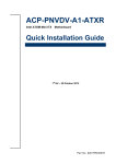
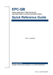
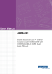
EMX-QM77 Intel® QM77 with Core™ i7 / i5 / i3 Mini-ITX Motherboard Quick Installation Guide 1st Ed – 23 July 2012 Part No: E2017EMXQ00R EMX-QM77 FCC Statement THIS DEVICE COMPLIES WITH PART 15 FCC RULES. OPERATION IS SUBJECT TO THE FOLLOWING TWO CONDITIONS: (1) THIS DEVICE MAY NOT CAUSE HARMFUL INTERFERENCE. (2) THIS DEVICE MUST ACCEPT ANY INTERFERENCE RECEIVED INCLUDING INTERFERENCE THAT MAY CAUSE UNDESIRED OPERATION. THIS EQUIPMENT HAS BEEN TESTED AND FOUND TO COMPLY WITH THE LIMITS FOR A CLASS "A" DIGITAL DEVICE, PURSUANT TO PART 15 OF THE FCC RULES. THESE LIMITS ARE DESIGNED TO PROVIDE REASONABLE PROTECTION AGAINST HARMFUL INTERFERENCE WHEN THE EQUIPMENT IS OPERATED IN A COMMERCIAL ENVIRONMENT. THIS EQUIPMENT GENERATES, USES, AND CAN RADIATE RADIO FREQUENCY ENERGY AND, IF NOT INSTALLED AND USED IN ACCORDANCE WITH THE INSTRUCTION MANUAL, MAY CAUSE HARMFUL INTERFERENCE TO RADIO COMMUNICATIONS. OPERATION OF THIS EQUIPMENT IN A RESIDENTIAL AREA IS LIKELY TO CAUSE HARMFUL INTERFERENCE IN WHICH CASE THE USER WILL BE REQUIRED TO CORRECT THE INTERFERENCE AT HIS OWN EXPENSE. Copyright Notice Copyright 2012 Avalue Technology Inc., ALL RIGHTS RESERVED. No part of this document may be reproduced, copied, translated, or transmitted in any form or by any means, electronic or mechanical, for any purpose, without the prior written permission of the original manufacturer. Trademark Acknowledgement Brand and product names are trademarks or registered trademarks of their respective owners. Disclaimer Avalue Technology Inc. reserves the right to make changes, without notice, to any product, including circuits and/or software described or contained in this manual in order to improve design and/or performance. Avalue Technology assumes no responsibility or liability for the use of the described product(s), conveys no license or title under any patent, copyright, or masks work rights to these products, and makes no representations or warranties that these products are free from patent, copyright, or mask work right infringement, unless otherwise specified. Applications that are described in this manual are for illustration purposes only. Avalue Technology Inc. makes no representation or warranty that such application will be suitable for the specified use without further testing or modification. 2 EMX-QM77 Quick Installation Guide Quick Installation Guide Life Support Policy Avalue Technology’s PRODUCTS ARE NOT FOR USE AS CRITICAL COMPONENTS IN LIFE SUPPORT DEVICES OR SYSTEMS WITHOUT THE PRIOR WRITTEN APPROVAL OF Avalue Technology Inc. As used herein: 1. Life support devices or systems are devices or systems which, (a) are intended for surgical implant into body, or (b) support or sustain life and whose failure to perform, when properly used in accordance with instructions for use provided in the labeling, can be reasonably expected to result in significant injury to the user. 2. A critical component is any component of a life support device or system whose failure to perform can be reasonably expected to cause the failure of the life support device or system, or to affect its safety or effectiveness. A Message to the Customer Avalue Customer Services Each and every Avalue’s product is built to the most exacting specifications to ensure reliable performance in the harsh and demanding conditions typical of industrial environments. Whether your new Avalue device is destined for the laboratory or the factory floor, you can be assured that your product will provide the reliability and ease of operation for which the name Avalue has come to be known. Your satisfaction is our primary concern. Here is a guide to Avalue’s customer services. To ensure you get the full benefit of our services, please follow the instructions below carefully. Technical Support We want you to get the maximum performance from your products. So if you run into technical difficulties, we are here to help. For the most frequently asked questions, you can easily find answers in your product documentation. These answers are normally a lot more detailed than the ones we can give over the phone. So please consult the user’s manual first. To receive the latest version of the user’s manual; please visit our Web site at: http://www.avalue.com.tw/ If you still cannot find the answer, gather all the information or questions that apply to your problem, and with the product close at hand, call your dealer. Our dealers are well trained Quick Installation Guide 3 EMX-QM77 and ready to give you the support you need to get the most from your Avalue’s products. In fact, most problems reported are minor and are able to be easily solved over the phone. In addition, free technical support is available from Avalue’s engineers every business day. We are always ready to give advice on application requirements or specific information on the installation and operation of any of our products. Please do not hesitate to call or e-mail us. Headquarters and Branch Avalue Technology Inc. Avalue USA Avalue Technology Inc. 7F, 228, Lian-cheng Road, Chung Ho City, Taipei, 9 Timber Lane, Marlboro, NJ 07746-1443 Taiwan Tel : (732) 414-6500 Tel:+886-2-8226-2345 Fax : (732) 414-6501 Fax : +886-2-8226-2777 Information : [email protected] Information :[email protected] Service : [email protected] Service: [email protected] BCM Advanced Research BCM Advanced Research an Avalue Company Avalue Europe 7 Marconi, Irvine, CA92618 Aalsgaarde, Denmark Tel: +1-949-470-1888 Tel: +45-7025-0310 Fax: +1-949-470-0971 Fax:+45-4975-5026 Information: [email protected] Information: [email protected] Web: www.bcmcom.com Service: [email protected] Avalue China Avalue Japan Avalue Technology Inc. Avalue Technology Inc. Room 805, Building 9,No.99 Tianzhou Rd., Avalue Europe A/S Moelledalen 22C, 3140 3F Ishiyama-Bldg, 1-6-1 Taito, Caohejing Development Area, Xuhui District, Shanghai Taito-Ku, Tokyo 110-0016 Japan Tel: +86-21-5169-3609 Tel : +81-3-5807-2321 Fax:+86-21-5445-3266 Fax : +81-3-5807-2322 Information: [email protected] Service: [email protected] 4 EMX-QM77 Quick Installation Guide Information : [email protected] Service : [email protected] Quick Installation Guide 1. Getting Started 1.1 Safety Precautions Warning! Always completely disconnect the power cord from your chassis whenever you work with the hardware. Do not make connections while the power is on. Sensitive electronic components can be damaged by sudden power surges. Only experienced electronics personnel should open the PC chassis. Caution! Always ground yourself to remove any static charge before touching the CPU card. Modern electronic devices are very sensitive to static electric charges. As a safety precaution, use a grounding wrist strap at all times. Place all electronic components in a static-dissipative surface or static-shielded bag when they are not in the chassis. 1.2 Packing List Before you begin installing your single board, please make sure that the following parts have been shipped. 1 x EMX-QM77 Mini-ITX Motherboard 1 x CD-ROM contains OS drivers/QIG/User’s Manual 2 x COM cable (9-pin) 1 x SATA cable (2 in 1,7-pin) 1 x I/O shield Quick Installation Guide 5 EMX-QM77 2. Hardware Configuration 6 EMX-QM77 Quick Installation Guide Quick Installation Guide 2.1 Product Overview Quick Installation Guide 7 EMX-QM77 2.2 Jumper and Connector List You can configure your board to match the needs of your application by setting jumpers. A jumper is the simplest kind of electric switch. It consists of two metal pins and a small metal clip (often protected by a plastic cover) that slides over the pins to connect them. To “close” a jumper you connect the pins with the clip. To “open” a jumper you remove the clip. Sometimes a jumper will have three pins, labeled 1, 2, and 3. In this case, you would connect either two pins. The jumper settings are schematically depicted in this manual as follows: A pair of needle-nose pliers may be helpful when working with jumpers. Connectors on the board are linked to external devices such as hard disk drives, a keyboard, or floppy drives. In addition, the board has a number of jumpers that allow you to configure your system to suit your application. If you have any doubts about the best hardware configuration for your application, contact your local distributor or sales representative before you make any changes. The following tables list the function of each of the board's jumpers and connectors. Specifications System CPU Intel Core i7/ i5/ i3 Pentium® / Celeron® Mobile CPU BIOS AMI 64Mb SPI ROM System Chipset Intel QM77 I/O Chipset Nuvoton NCT6776F Memory Two 204-pin SODIMM support up to 16GB dual channel DDR3 1600/ 1333 SDRAM, Non-ECC Watchdog Timer Reset: 1 to 255 sec/min per step H/W Status Monitor Monitoring temperature, voltage and cooling fan status. Auto throttling control when CPU overheats. Expansion Slots 1 PCI-E x 16 Gen. 3, 1 Mini PCI-E, 1 CFast Power State S1, S3, S4, S5 TPM TPM 1.2 by Infineon SLB9635 RAID RAID 0, 1, 5 and 10 Wake up / Boot on LAN LAN (WOL,PXE) 8 EMX-QM77 Quick Installation Guide Quick Installation Guide Smart Fan Control Yes Display Chipset Intel GMA HD 4000 /2500 (22nm) , 3000/2000(32nm) Display Memory Shared Memory, up to 256MB Dual Display VGA + LVDS, VGA + HDMI, VGA + DVI, LVDS + HDMI, LVDS + DVI, HDMI + DVI VGA Onboard, supports max resolution 2048 x 1536 (@75Hz) LVDS Onboard 24-bit LVDS, supports max resolution 1920 x 1200 HDMI Onboard HDMI 1.3, supports max resolution 1920 x 1200 DVI Onboard DVI-D, supports max resolution 1920x1200 LVDS Backlight Yes Audio Audio Codec Realtek AL892, 5.1 Channel HD Audio Audio Interface Line-in, line-out, Mic-in, S/PDIF Out, Front Audio Header Ethernet LAN1 Intel 82579LM GbE LAN supports iAMT 8.0 LAN2 Intel 82583V GbE LAN Jumpers Label Function Note JCMOS1 Clear CMOS Normal * JCOMPWR2 COM2 COM3 RI/+5V/+12V Select RI Clear CMOS +5V +12V JCOMPWR3 JLVDS_BKL1 BL POWER SELECT 5V 3.3V AT MODE ATX MODE 1.+5V 2. BRIGHT 1 3. 3.3V JPSON 1.ATSEL IN 2.PWRBT 3.ATXSEL IN Connectors Label CPU_FAN Function CPU Fan Connector Note 1.GND 2.CPUFAN1_VCC(PWM) 3.CPUFAN1_IO Quick Installation Guide 9 EMX-QM77 SYS_FAN1 System Fan 1.GND 2.SYSFAN1_VCC(PWM) 3.SYSFAN1_IO Connector Connectors Label Function COM2 Serial Port COM3 Connector F_PANEL1 Intel Front Note 1.DCD 2.RXD 3.TXD 4.DTR 5.GND 1.HDDLED+ 2.POWERLED+ 3.HDDLED4.POWERLED5.GND 6.PWSWITCH 7.RESET 8.GND 9.NC Panel connector JLVDS 6.DSR 7.RTS 8.CTS 9.RI/PWR 24-bit LVDS Connector 39.VDD(+12V) 37.GND 40.VDD(+12V) 38.GND 35.LVDS_B_CK- 36.LVDS_A_CK- 33.LVDS_B_CK+ 34.LVDS_A_CK+ 31.GND 32.GND 29.LVDS_B3- 30.LVDS_B2- 27.LVDS_B3+ 28.LVDS_B2+ 25.GND 26.GND 23.LVDS_B1- 24.LVDS_B0- 21.LVDS_B1+ 22.LVDS_B0+ 19.GND 20.GND 17.LVDS_A3- 18.LVDS_A2- 15.LVDS_A3+ 16.LVDS_A2+ 13.GND 14.GND 11.LVDS_A1- 12.LVDS_A0- 9.LVDS_A1+ 10.LVDS_A0+ 7.GND 8.GND 5.I2C_CLK 6.I2C_DATA 3.VDD(+3.3V) 4.VDD(+5V) 1.VDD(+3.3V) 2.VDD(+5V) 10 EMX-QM77 Quick Installation Guide Quick Installation Guide JBKL LCD Inverter Connector JLPC1 FPAUD1 LPC Connector 1.NC 3.LPC_AD3 5.LPC_AD1 7.LPC_FRAME# 9. 11.CLK33M_LPC Audio Mic.-In 10.LINE_JD 8.NC 6.MIC2_JD 4.PRESENSE 2.GND & Line-Out Connector JGPIO1 GPIO Connector SPDIF_OUT SPDIF OUT Connector USB56 USB 2.0 Connector USB78 USB910 USB1112 KBMS2 1.+12V 2.GND 3.ENBKL 4.VR 5.+5V KB/Mouse Connector 1.SIO_GPIO0 3.SIO_GPIO1 5.SIO_GPIO2 7.SIO_GPIO3 9.SMB_CLK_RESUME 11.GND 2.+3.3 4.PRST_SIO# 6.LPC_AD2 8.LPC_AD0 10.GND 12.GND 9.LIN2_L 7.FIO_SENSE 5.LIN2_R 3.MIC2_R 1.MIC2_L 2.SIO_GPIO4 4.SIO_GPIO5 6.SIO_GPIO6 8.SIO_GPIO7 10.SMB_DAT_RESUME 12.VCC GPIO 1.+5V 2. 3.SPDIF OUT 4.GND 9.NC 8.GND 7.GND 6.USB+ 5.USB+ 4.USB3.USB 2.USB+5V 1.USB+5V 1.KB b CLK 2.KB b DAT 3.MS b DAT 4.GND 5.VCC_KBMS 6.MS_b_CLK Quick Installation Guide 11