1
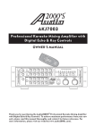
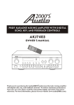
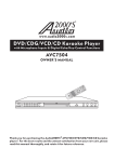
PROFESSIONAL FOUR-CHANNEL
UHF WIRELESS SYSTEM WITH 16
ADJUSTABLE FREQUENCIES
AWM6526U
OWNER'S MANUAL
®
Thank you for purchasing the Audio2000'S professional four-channel UHF
wireless system with 16 adjustable frequencies! For the best results and the
utmost satisfaction from your new unit, please read this manual thoroughly, and
retain it for future reference.
TABLE OF CONTENTS
Warning .......................................................................... 1
Precautions ..................................................................... 1
Package Contents ............................................................ 2
Quick Setup ..................................................................... 3
Features ......................................................................... 6
System Configurations ..................................................... 7
System Functions ............................................................ 8
Operation - AWR6526U .................................................... 8
Operation - AWX6526U ................................................... 10
Operation Notes ............................................................. 12
Specifications ................................................................ 13
Troubleshooting ............................................................. 14
Service Information ........................................................ 16
WARNING
To prevent fire or shock hazard, do not expose the
unit to rain or moisture.
Dangerously high voltages are present inside the
unit. Do not open the cabinet. Refer servicing to
qualified personnel only.
PRECAUTIONS
On Safety
* Operate only on designated AC power supply (120V AC in North
America).
* Should any liquid or solid object fall into the cabinet, unplug the
unit and have it checked by qualified personnel before operating
it any further.
-1-
* Unplug the unit from the wall outlet or set the Master switch to
OFF if it is not to be used for several days.
* To disconnect the cord, pull it out by the plug. Never pull the cord
itself.
On Installation
* Allow adequate air circulation to prevent internal heat build-up.
Do not place the unit on surfaces (rugs, blankets, etc.) or near
materials (curtains, draperies) that may block the ventilation
holes.
* Do not install the unit in a location near heat sources such as
radiators or air ducts, or in a place subject to direct sunlight,
excessive dust, mechanical vibration or shock.
On Repackaging
Do not throw away the carton and packing materials. They make
an ideal container in which to transport the unit. When shipping the
unit to another location, repack it as it was originally packed at the
factory.
PACKAGE CONTENTS
Items
Quantities
AWR6526U Receiver
Wireless Transmitters
(Handheld Microphones and/or Body-Pack
Transmitters )
AC/DC Adaptor
Antennas
¼” to ¼” Cable
Rack-Mount Ear Kit
AA Batteries (Two for Each Transmitter)
Owner's Manual
- 2-
1
4
1
2
1
1
8
1
QUICK SETUP
A. Remove packing material
B. Install the AWR6526U receiver
1.
Place the AWR6526U receiver at a location at least 3.5 feet (1 meter)
away from the ground and all the walls. Also, keep the AWR6526U
receiver away from any electro-magnetic noise sources as far as
possible.
2. Mount both the antennas onto the left and right TNC antenna jacks. Make
sure that any of the antennas is not enclosed in a large metal body.
3.
Plug the supplied AC/DC adaptor 12VDC output connector to the
AWR6526U receiver's DC input, and then plug the AC input of the
adaptor to a 120V AC outlet (North America).
4. Connect the outputs of the AWR6526U receiver to microphone inputs of a
mixer or a sound system. In order to do so, (1) you could use the
supplied microphone cable (a cable with ¼” connectors on both ends) to
connect from the unbalanced output (an ¼” jack) to an ¼” microphone
input on a mixer or a sound system; or (2) you could get four balanced
microphone cables (cables with a male XLR connector at one end and a
female XLR connector on the other end; not included in the package) to
connect from all four balanced outputs (male XLR jacks) to four balanced
microphone inputs (female XLR jacks) on a mixer or a sound system.
5. Turn all four audio level adjustment knobs all the way to the minimal
audio position. Press the power On/Off switch to turn on the AWR6526U
receiver. After the power of the AWR6526U receiver is turned on, the
power LED indicator will be turned on. (Note: The audio level adjustment
knobs will be adjusted to its optimal position after the transmitters are
turned on as discussed in the following section.)
C. Set up the transmitters
- 3-
(a) Set up the handheld transmitter
1. Open the battery cover of the handheld transmitter by sliding the battery
cover out.
2. Place two 1.5V AA batteries into the battery housing with the battery
polarity orientation as indicated.
3. Place the battery cover back on the handheld transmitter by sliding the
battery cover back in.
4. Turn on the power of the handheld transmitter.
(b) Set up the body-pack transmitter
1. Open the battery cover of the body-pack transmitter by pushing the latch
button (refer to numerals 31 & 32 on pages 11 and 12) inwards (There is a
concaved opening and the latch button is at the lower side of the
opening) and flipping open the battery cover.
2. Place two 1.5V AA batteries into the battery compartment with the battery
polarity orientations as indicated.
3. Plug the supplied headset or lavalier microphone into the microphone
input (a mini XLR jack) on the body-pack transmitter. When the lavalier
microphone is used, the AUDIO INPUT ATTENUATION SWITCH (refer
to numeral 27 on page 11) needs to be set to the 0dB position. When the
headset microphone is used, the AUDIO INPUT ATTENUATION
SWITCH needs to be set to the -10dB position.
4. Flip the cover down in the direction toward the latch button to close the
battery cover.
5. Turn on the power of the body-pack transmitter. The green LED indicator
will be turned on.
D. Setting up the AWM6526U system
1.
The best wireless reception can be achieved by selecting the DIP
switch setup to all channels on the AWR6526U receiver (Selections 0
through 7; Totally 8 selections) as follows:
- 4-
(NOTE: 0 = DIP Switch Down; 1 = DIP Switch Up)
Selection
Channel A
Channel B
Channel C
Channel D
Number DIP Switches DIP Switches DIP Switches DIP Switches
0
12 3 4
12 3 4
12 3 4
12 3 4
1
12 3 4
12 3 4
12 3 4
12 3 4
2
12 3 4
12 3 4
12 3 4
12 3 4
3
12 3 4
12 3 4
12 3 4
12 3 4
4
12 3 4
12 3 4
12 3 4
12 3 4
12 3 4
12 3 4
12 3 4
12 3 4
12 3 4
12 3 4
12 3 4
12 3 4
12 3 4
12 3 4
12 3 4
12 3 4
5
6
7
2.
If the transmitters need to have their frequencies adjusted to match
to the receiver frequencies, utilize the infrared signal windows as
follows:
( For Sync A or B )
( For Sync C or D )
Following the previous sections to open the battery covers of the
transmitters (either handheld or body-pack). Keep both transmitters'
power on. Press the Channel A Sync button (refer to numeral 6 on page 8)
and then align the INFRARED SIGNAL RECEIVING WINDOW (refer to
numeral 20 on page 10 for handheld transmitter and numeral 26 on page
11 for body pack transmitter) to the IR AB Window (refer to numeral 7 on
pages 8 and 9) of the AWR6526U receiver, the above transmitter will be
synchronized to the Channel A frequency and the Channel A RF LED light
(Green, refer to numeral 4 on page 8) will be turned on to indicate that the
above transmitter's signal has been received by the receiver. Press the
Channel B Sync button and then align the INFRARED SIGNAL
RECEIVING WINDOW of the second transmitter to the IR AB Window of
the AWR6526U receiver, the above transmitter will be synchronized to the
Channel B frequency and the Channel B RF LED light (Green) will be
turned on to indicate that the above transmitter's signal has been
received by the receiver. Press the Channel C Sync button and then align
the INFRARED SIGNAL RECEIVING WINDOW of the third transmitter
- 5-
to the IR CD Window of the AWR6526U receiver, the above transmitter
will be synchronized to the Channel C frequency and the Channel C RF
LED light (green) will be turned on to indicate that the above transmitter's
signal has been received by the receiver. Press the Channel D Sync
button and then align the INFRARED SIGNAL RECEIVING WINDOW of
the fourth transmitter to the IR CD Window of the AWR6526U receiver, the
above transmitter will be synchronized to the Channel D frequency and
the Channel D RF LED light (green) will be turned on to indicate that the
above transmitter's signal has been received by the receiver.
3.
Adjust the volume control knobs on the AWR6526U to the maximum
position and adjust the mixer or the sound system, which is connected to
the AWR6526U microphone outputs, to have an optimal sound level. If the
sound seems to be abnormal, it may be caused by the overdriven inputs of
the mixer or the sound system. Adjust the volume control knobs on the
AWR6526U to a lower level until the abnormal sound quality is removed.
The AWM6526U is now ready.
4.
If more than one AWM6526U are to be used, the frequencies of the
AWM6526U systems other than the first one need to be adjusted to be
different from one another. First, refer to the DIP Selection Diagram on
the top portion of page 5 to select the DIP switch selection number that is
different from the other AWR6526U receivers to be used at the same time.
(For instance, if there are three AWR6526U receivers to be used at the
same time and the frequencies of first two receivers have been selected
to be Selection 0 and Selection 2 from the DIP Selection Diagram, the
third AWR6526U receiver can select any DIP switch selection numbers
other than Selection 0 and Selection 2.) Then, refer to step one of this
section for the frequency transmitters' synchronization details.
AWM6526U SYSTEM
FEATURES
1. UHF Band Frequencies
2. 19” Rack-Mountable Receiver Including Rack-Mount-Ear Kit
3. Agile Frequencies with PLL (Phase-Lock Loop) 16 Adjustable
Frequencies
4. Including Four Wireless Transmitters (Comprising Combinations of
Handheld Microphones, Lavaliere Microphones, Headset Microphones
and or the Guitar transmitters)
5. Four Independent Balanced XLR outputs and One Mixed Unbalanced ¼”
Output
6. Microcontroller (CPU) Controlled
7. Automatic Synchronizing the Receiver and Transmitter Frequency
through Infrared Signal
- 6-
8. Four Independent Volume Control Knobs (One for Each Channel)
9. Integrated Antenna for Effective RF Output and High Transmission
Quality
10. One Power LED indicator, Four AF Red LED indicators, and Four RF
Green LED indicators
11. Rugged Metal Rack-Mountable Receiver Chassis
12. Operating Range up to 100ft
13. 12VDC Power Supply
SYSTEM CONFIGURATIONS
● AWM6526U - Comprising an AWR6526U receiver and four AWX6526U
wireless handheld microphones
● AWM6526UD - Comprising an AWR6526U receiver and two AWX6526U
wireless handheld microphones and two AWX6526UH wireless headset
microphones
● AWM6526UE - Comprising an AWR6526U receiver and two AWX6526U
wireless handheld microphones and two AWX6526UM wireless lavalier
microphones
● AWM6526UF - Comprising an AWR6526U receiver and two AWX6526UH
wireless headset microphones and two AWX6526UM wireless lavalier
microphones
● AWM6526UG - Comprising an AWR6526U receiver and four AWX6526UG
wireless guitar transmitters
● AWM6526UH - Comprising an AWR6526U receiver and four AWX6526UH
wireless headset microphones
● AWM6526UL - Comprising an AWR6526U receiver and three AWX6526U
wireless handheld microphones and one AWX6526UM wireless lavalier
microphone
● AWM6526UM - Comprising an AWR6526U receiver and four AWX6526UM
wireless lavalier microphones
● AWM6526UN - Comprising an AWR6526U receiver and one AWX6526U
wireless handheld microphone and three AWX6526UM wireless lavalier
microphones
● AWM6526UR - Comprising an AWR6526U receiver and three AWX6526U
wireless handheld microphones and one AWX6526UG wireless guitar
transmitter
● AWM6526UX - Comprising an AWR6526U receiver and three AWX6526U
wireless handheld microphones and one AWX6526UH wireless headset
microphone
- 7-
SYSTEM FUNCTIONS
AWR6526U RECEIVER
FRONT PANEL
1 2
3
45 6 7 6 54 3
3
45 6 7 6 54 3
1. POWER ON/OFF SWITCH
2. POWER LED INDICATOR (Red)
3. AUDIO LEVEL ADJUSTMENT KNOBS --- There are four audio level
adjustment knobs, one for each channel. These four knobs are used to
raise or lower the audio levels.
4. RADIO FREQUENCY (RF) SIGNAL INDICATORS (Green) -- These RF
indicators are used to indicate the wireless signals being received from
the transmitters.
5. AUDIO FREQUENCY (AF) SIGNAL INDICATORS (Red) --- These AF
indicators are used to indicate the audio input signals being received
from the transmitters.
6. INFRARED SIGNAL SYNC BUTTONS --- There are four infrared signal SYNC
buttons, one for each Channel. Keep all four transmitters' power on.
Press the Channel A Sync button (SYNC A) and then align the
INFRARED SIGNAL RECEIVING WINDOW (refer to numeral 20 on page
10 for handheld transmitter and numeral 26 on page 11 for body pack
transmitter) to the IR AB (see numeral 7) Window of the AWR6526U
receiver, the above transmitter will be synchronized to the Channel A
frequency and the Channel A RF LED light (green) will be turned on to
indicate that the above transmitter's signal has been received by the
receiver. Press the Channel B Sync button (SYNC B) and then align the
INFRARED SIGNAL RECEIVING WINDOW to the IR AB Window of the
AWR6526U receiver, the above transmitter will be synchronized to the
Channel B frequency and the Channel B RF LED light (green) will be
turned on to indicate that the above transmitter's signal has been
received by the receiver. Press the Channel C Sync button (SYNC C)
and then align the INFRARED SIGNAL RECEIVING WINDOW to the IR
CD Window of the AWR6526U receiver, the above transmitter will be
synchronized to the Channel C frequency and the Channel C RF LED
light (green) will be turned on to indicate that the above transmitter's
signal has been received by the receiver. Press the Channel D Sync
button (SYNC D) and then align the INFRARED SIGNAL RECEIVING
- 8-
WINDOW to the IR CD Window of the AWR6526U receiver, the above
transmitter will be synchronized to the Channel D frequency and the
Channel D RF LED light (green) will be turned on to indicate that the
above transmitter's signal has been received by the receiver.
7. INFRARED SIGNAL EMISSION WINDOWS (IR WINDOWS) --- There are two
infrared signal emission windows, one for Channels A & B (IR AB) and
one for Channels C & D (IR CD).
REAR PANEL
8
9
12 3 4
12 3 4
10
10
12 3 4
12 9
9
10
12 3 4
11
10
12
9
8
8. TNC ANTENNA JACKS --- There are two TNC antenna jacks, one for
Channels A & B (ANT AB) and the other for Channels C & D (ANT CD).
9. BALANCED MICROPHONE OUTPUTS (XLRM Jacks) --- There are four
independent balanced microphone output XLRM jacks, one for each
channel.
10. 16-FREQUENCY DIP SWITCHES - There are four sets of 16-frequency DIP
switches, one for each channel. The sixteen (16) adjustable frequencies
can be adjusted by setting the DIP switches. The frequencies
corresponding to the DIP switch settings are listed as follows: (NOTE: 0
= DIP Switch up; 1 = dip Switch Down)
DIP Switches
1234
0000
1000
0100
1100
0010
1010
0110
1110
0001
1001
0101
1101
0011
1011
0111
1111
Channel
Number
0
1
2
3
4
5
6
7
8
9
10
11
12
13
14
15
Channels A & C
Frequencies (MHz)
663.050
670.650
663.300
666.050
667.100
667.850
669.350
662.500
663.150
668.050
664.300
666.950
664.550
662.350
660.200
661.800
- 9-
Channels B & D
Frequencies (Mhz)
688.700
679.400
677.500
682.750
678.450
678.700
680.950
681.500
675.550
682.250
677.350
681.950
678.450
679.050
684.000
678.950
11. UNBALANCED MICROPHONE OUTPUT (1/4” Jack) --- This is a mixed
unbalanced microphone output from all four channels (mixed output).
12. 12 DC INPUT (Tip Positive)
HANDHELD WIRELESS MICROPHONE
19
13
14
15
16
17 18
20
13. MICROPHONE WINDSCREEN
14. POWER ON/OFF LED INDICATOR
15. POWER ON/OFF SWITCH
16. HANDHELD MICROPHONE BODY
17. BATTERY COMPARTMENT
18. BATTERIES --- 2 X AA alkaline batteries or 2 X NiMH rechargeable AA
batteries
19. MICROPHONE BATTERY COVER
20. INFRARED SIGNAL RECEIVING WINDOW --- This IR window is hidden
under the microphone battery cover (numeral 19). In order to
synchronize the frequency of the handheld microphone to the frequency
of the AWR6526U receiver, the microphone battery cover needs to be
opened and set aside to expose this IR window. Place this window 4
inches (10cm) away and facing the receiver IR window to proceed to the
transmitter frequency synchronization.
- 10 -
BODY-PACK WIRELESS TRANSMITTER
22 21
24
24
21
23
23
30
30
30
31
27
26
28
29
23
22 21
24
25
32
21. POWER ON/OFF & MUTE BUTTON --- This button is to be used as a power
On/Off switch and as a mute button. When the body-pack transmitter
power is off, press this button steadily to turn on the power and the green
Power LED Indicator will be turned on. While the power is on, press this
button steadily to turn off the power and the green Power LED Indicator
will be turned off. If the power is on and this button is pressed once, this
button will have the body-pack transmitter muted and the power LED
indicator will turn yellow. If the body-pack transmitter is muted, press this
button once again to turn off the mute and the power LED indicator will
turn back to green. If the power level of the AA batteries is low, the power
LED indicator will start to blink between green and yellow.
22. POWER LED (Green) /MUTE LED (Yellow) INDICATOR
23. ANTENNA
24. MICROPHONE INPUT
25. BATTERY COMPARTMENT COVER
26. INFRARED SIGNAL RECEIVING WINDOW --- This IR window is hidden
under the body-pack battery cover (numeral 25). In order to synchronize
the frequency of the body-pack transmitter to the frequency of the
AWR6526U receiver, the body-pack battery cover needs to be flipped
open to expose this IR window. Place this window 4 inches (10cm) away
and facing the receiver IR window to proceed to the transmitter
frequency synchronization.
27. AUDIO INPUT ATTENUATION SWITCH (0dB & -10dB) --- This switch needs
to be set to the 0dB position when the lavalier microphone is used. This
switch needs to be set to the -10dB position when the headset
microphone is used.
- 11 -
28. BATTERY COMPARTMENT
29. BATTERIES --- 2 X AA alkaline batteries or 2 X NiMH rechargeable AA
batteries
30. BELT CLIP
31. BATTERY COMPARTMENT COVER LATCH
32. LATCH BUTTON
OPERATION NOTES
1. The AWX6526U, AWX6526UG, AWX6526UH, and AWX6526UM need to
be turned off before changing the AA batteries.
2. Signal dropout or unexpected noise may be caused by a low battery or by
an excessive distance between the transmitter and the receiver. If you
encounter signal dropout or unexpected noise, please check the
batteries first. If the batteries are still fresh, try to readjust the antennas
on the AWR6526U receiver.
3. Avoid placing the receiver in a corner to prevent any RF reception
deterioration.
4. Avoid placing the receiver antennas close to an obstruction or close to
any metal surface.
5. Try to place the receiver as far away from the digital equipment, including
computers and CD players, as possible.
6. If more than one AWR6526U wireless microphone receivers are stacked
together or placed in a rack, do not let the antennas touch each other or
cross each other.
7. Before the AWM6526U is to be used in a new location, place the
AWR6526U receiver at the intended location and walk through the area
with the transmitters to locate any radio frequency blind spots, where a
momentary loss of sound or short period of noise may occur whenever
the transmitters are moved to these spots.
8. Do not drop the transmitter on the floor or strike the transmitter with any
object.
9. Always turn off the transmitter and remove the batteries if the transmitter
is not to be used for a period of time to prevent the transmitter from being
damaged by leaking batteries.
- 12 -
SPECIFICATIONS
AWR6526U RECEIVER
RECEIVING MODE
SUPERHETERODYNE DOUBLE
CONVERSION
INTERMEDIATE FREQUENCIES
ANTENNA INPUT
SENSITIVITY
SENSITIVITY REGULATING RANGE
RF SQUELCH
WEIGHT
DIMENSIONS (W X D X H)
110MHz, 10.7MHz
TNC / 50Ω
15dBuV
15-30dBuV
>80dB
4.2 lbs (1.91 Kg)
16.5” X 9.4” X 2.0” (420 X 240 X 50 mm)
AWX6526U TRANSMITTER
ANTENNA
EMISSION POWER
MAX SPL
IMAGE SPURIOUS
MICROPHONE CARTRIDGE
BATTERIES
BUILT-IN ANTENNA, QUARTER-WAVE WHIP
ANTENNA
8mW
130dB
>70dB
HANDHELD MICROPHONE: DYNAMIC
LAVALIER or HEADSET: ELECTRET CONDENSER
ALKALINE AA X 2 or RECHARGEABLE AA X 2
AWM6526U SYSTEM
FREQUENCY RANGE
MODULATION MODE
OSCILLATION MODE
DEVIATION
CHANNEL WIDTH
S/N RATIO
TOTAL HARMONIC DISTORTION
FREQUENCY RESPONSE
UHF
FM
VCO + PLL
±45KHz (COMPRESS-EXPAND and
AUTOMATIC-VOLUME- LIMIT CIRCUIT)
30MHz
>85dB
<0.3% (1 KHz, A WEIGHTING)
80 - 15,000 Hz ( ±3dB)
- 13 -
TROUBLESHOOTING
Should problems occur, they are, in many cases, due to simple operation
mistakes or the like. On the basis of the following checks, you will be able to
rectify a number of problems yourself without difficulty. If the problem cannot be
remedied after the following checks, please consult your dealer.
PROBLEM
POSSIBLE CAUSES
SOLUTIONS
Turn on the transmitter.
No sound and no The power of the
transmitter is off.
RF signal
Incorrect AA-battery
Correct the AA-battery polarity.
polarity in the transmitter.
Antenna is not on the
receiver or bad antenna
connection.
Transmitter too far away
from the antenna or RF
signal blocked.
No sound while
RF and AF
signals normal.
Install the antenna or check the
antenna connection.
Reposition the transmitter to
closer area or remove the RF
signal block.
Receiver volume turned to Adjust the volume control knob
minimum.
to have an optimal volume
output.
Receiver audio cable is
Connect, repair or replace the
missing or defective.
audio cables.
Volume control of the
Adjust the volume control on the
sound system connected sound system which is
to the AWR6526U receiver connected to the AWR6526U
is set to minimum.
receiver.
The microphone cartridge Return transmitter to factory or
of the transmitter is
authorized service station for
defective.
service.
No sound while
RF signal is
normal and AF
signal does not
exist.
Loud noise from Interference signal at that
frequency.
receiver only
when the
transmitter is off.
Receiver is placed too
close to an interference
source, such as a
computer, digital device,
or CD player.
- 14 -
Reposition receiver or adjust the
antenna orientation.
Select another operating
frequency.
Move the receiver to another
location.
Select another operating
frequency.
Loud noise from Another transmitter is
receiver even
using the same frequency.
when the
transmitter is on. Interference signal at that
frequency.
Receiver is placed too
close to an interference
source, such as a
computer, digital device,
or CD player.
Turn off another transmitter or
change to a channel with a
different frequency.
Distorted sound
Replace transmitter battery.
Low transmitter battery
level.
Select another operating
frequency.
Move the receiver to another
location.
Select another operating
frequency.
The volume control on the Turn down the volume control on
receiver is set too high,
the AWR6526U receiver.
overloading the subsequent
sound device input.
Short range or
signal dropouts.
Momentary loss
of sound when
transmitter is
moved around
the performing
area.
Low transmitter battery
level.
Poor antenna reception.
Interference Signal.
Replace transmitter battery.
Reposition antenna or receiver.
Select another operating
frequency.
Too many obstacles
Move the obstacles or move the
between the receiver and receiver away from nearby metal
transmitter.
objects.
Reposition the receiver. If the
Radio frequency (RF)
momentary loss of sound
blind spots.
problem cannot be removed,
walk through the performing
area and mark “Blind” spots.
Avoid these “Blind” spots during
performance.
- 15 -
SERVICE INFORMATION
SHIPPING DAMAGE
If the shipping carton is found to be damaged, notify the delivery company
immediately. Save the damaged carton as evidence for the delivery
company to inspect. It is the responsibility of the consignee to file a claim
with the delivery company for any damage that occurs during shipping. In
the case that the shipping carton is in good condition but the unit is damaged
®
or defective, call Audio2000'S at 805/523-2759.
FACTORY SERVICE
®
If the equipment needs factory service, call Audio2000'S at 805/523-2759
for a Return Authorization number (RA number) and the address of the
authorized service representatives. Insure and ship the product, prepaid, in
its original carton along with proof of purchase in the form of a bill of sale or
receipted invoice to the above address. Please clearly write the RA number
on the shipping carton. Also enclose a note describing the problem along
with any other helpful information such as where and how the unit was used.
LIMITED WARRANTY
®
H&F Technologies, Incorporated (H&F) hereby warrants that Audio2000'S
products will be free from defects in material and workmanship for a period of
1 (one) year from date of purchase. At its option, H&F will repair or replace
the defective product and promptly return it to you.
The Limited Warranty will not cover any item that has been, in H&F's
estimation, subject to alteration, misuse, neglect, accident or improper
installation. In addition, any service not performed by H&F or an authorized
service center will terminate terms of this warranty. Normal wear and tear of
this product will not be covered by this or any implied warranty.
No liability will be accepted for damages/loss directly caused from the use of
this product. H&F's liability shall be limited to the repair/replacement of this
product if found to be defective.
© 2013 H & F Technologies, Incorporated
- 16 -
(website: www.audio2000s.com)