1
Intel® Integrated RAID Software
Software Installation and User’s Guide, Version 1.2.3
November 2002
Preliminary
Order Number: C15971-002
Information in this document is provided in connection with Intel® products. No license, express or implied, by estoppel or otherwise, to any intellectual
property rights is granted by this document. Except as provided in Intel's Terms and Conditions of Sale for such products, Intel assumes no liability
whatsoever, and Intel disclaims any express or implied warranty, relating to sale and/or use of Intel products including liability or warranties relating to
fitness for a particular purpose, merchantability, or infringement of any patent, copyright or other intellectual property right. Intel products are not
intended for use in medical, life saving, or life sustaining applications.
Intel may make changes to specifications and product descriptions at any time, without notice.
Designers must not rely on the absence or characteristics of any features or instructions marked “reserved” or “undefined.” Intel reserves these for
future definition and shall have no responsibility whatsoever for conflicts or incompatibilities arising from future changes to them.
The RAID Adapter may contain design defects or errors known as errata which may cause the product to deviate from published specifications.
Current characterized errata are available on request.
This RAID Adapter as well as the software described in it is furnished under license and may only be used or copied in accordance with the terms of
the license. The information in this manual is furnished for informational use only, is subject to change without notice, and should not be construed as
a commitment by Intel Corporation. Intel Corporation assumes no responsibility or liability for any errors or inaccuracies that may appear in this
document or any software that may be provided in association with this document. Except as permitted by such license, no part of this document may
be reproduced, stored in a retrieval system, or transmitted in any form or by any means without the express written consent of Intel Corporation.
Copyright © Intel Corporation, 2002
*Other names and brands may be claimed as property of others.
Software Installation and User’s Guide
Contents
1
Introduction
1.1
Using the User Documentation Set .............................................................................................13
1.1.1
Document Formats ....................................................................................................14
About This Guide.........................................................................................................................14
1.2.1
Installation Guide .......................................................................................................15
1.2.2
User’s Guide ..............................................................................................................16
RAID Levels ................................................................................................................................17
1.3.1
RAID 0 - Data Striping ...............................................................................................17
1.3.2
RAID 1 - Disk Mirroring/Disk Duplexing .....................................................................17
1.3.3
RAID 4 - Data Striping With a Dedicated Parity Drive ...............................................18
1.3.4
RAID 5 - Data Striping with Striped Parity .................................................................19
1.3.5
RAID 10 - Combination of RAID 1 and RAID 0..........................................................19
1.3.6
Levels of Drive Hierarchy Within the Intel® Integrated RAID Firmware .....................20
Transparency of Host Drives .......................................................................................................21
1.4.1
Using CD-ROMs, DATs, Tapes, etc. .........................................................................22
1.2
1.3
1.4
2
Getting Started
2.1
2.2
2.3
Determine the RAID Configuration ..............................................................................................24
Create the RAID Driver Installation Diskette ...............................................................................25
2.2.1
Preferred Method.......................................................................................................25
2.2.2
Alternative Methods ...................................................................................................27
Install the IIR Controller ...............................................................................................................29
3
Quick Installation
3.1
3.2
3.3
3.4
Roadmap for Quick Installation ...................................................................................................31
Create a Bootable Host Drive—RAID 1 Mirrored Array...............................................................32
Create a Bootable Host Drive—RAID 5 Disk Array with Hot Fix .................................................35
Microsoft Windows 2000 and Windows NT Quick Installation.....................................................40
3.4.1
Minimum Requirements .............................................................................................40
3.4.2
OS Installation Procedures ........................................................................................40
Novell NetWare 4.2x, 5.x and 6.x Quick Installation....................................................................41
3.5.1
Minimum Requirements .............................................................................................42
3.5.2
OS Installation Procedures ........................................................................................42
SCO UnixWare 7.1.1 and 8.0 Quick Installation .........................................................................44
3.6.1
Minimum Requirements .............................................................................................44
3.6.2
OS Installation Procedures ........................................................................................44
RAID Software Suite Quick Installation .......................................................................................45
3.7.1
Microsoft Windows 2000 and NT 4.0 .........................................................................45
3.7.2
Novell NetWare 4.2x, 5.x and 6.x ..............................................................................46
3.7.3
SCO UnixWare 7.1.1 or 8.0 .......................................................................................47
3.5
3.6
3.7
4
Installing Microsoft Windows 2000, Windows XP Professional or Windows NT
4.1
Operating System Installation Procedures ..................................................................................48
4.1.1
Pre-Installation Requirements Checklist ....................................................................48
4.1.2
Installing an Operating System onto a Host Drive .....................................................49
4.1.3
Installing an OS onto an IDE or SCSI Disk Drive not Attached to the IIR Controller .51
Software Installation and User’s Guide
3
4.1.4
4.2
Upgrading/Replacing Windows NT 4.0 Server Currently Installed on a Host Drive or
Single Disk52
4.1.5
Installation to an Existing OS..................................................................................... 54
4.1.6
Swapping Out / Replacing Compatible IIR Controllers in Windows 2000 and Windows
XP Professional56
Configuring the RAID Configuration Service ............................................................................... 57
5
Installing Linux
5.1
Before you begin ......................................................................................................................... 61
5.1.1
Linux Drivers and Updates ........................................................................................ 61
5.1.2
Available Drivers and Tools on the RAID Software Suite CD-ROM .......................... 62
5.1.3
Assumptions About Path Names ............................................................................... 62
General Installation Notes ........................................................................................................... 62
5.2.1
Minimum Hardware Requirements ............................................................................ 62
Installing Red Hat Linux 7.x on a Host Drive............................................................................... 63
Installing an IIR Controller onto an Existing Linux Server ........................................................... 64
5.4.1
Installation of Driver Sources from the RAID Software Suite CD-ROM..................... 64
GDT Driver Parameters............................................................................................................... 65
5.5.1
Reservation of SCSI Devices .................................................................................... 65
5.5.2
Further Driver Parameters ......................................................................................... 66
Installation of StorCon Monitoring Utility ..................................................................................... 66
5.6.1
Installation of StorCon from the RAID Software Suite CD-ROM ............................... 66
5.6.2
Using StorCon Monitoring Utility................................................................................ 67
Remote Monitoring with the Intel SRCD Remote Access Service .............................................. 67
5.7.1
SRCD Installation Instructions from the RAID Software Suite CD-ROM ................... 68
5.2
5.3
5.4
5.5
5.6
5.7
6
Installing Novell NetWare
6.1
Pre-Installation Requirements Checklist ..................................................................................... 70
6.1.1
Minimum Hardware Requirements ............................................................................ 70
6.1.2
Minimum Software Requirements.............................................................................. 70
New installation of NetWare 4.2x, 5.xx and 6.x........................................................................... 71
6.2.1
New Installation of NetWare 4.20 with the SRCRX.HAM Driver................................ 71
6.2.2
New Installation of NetWare 5.0 with the SRCRX.HAM Driver.................................. 71
6.2.3
New Installation of NetWare 5.1x with the SRCRX.HAM Driver................................ 72
6.2.4
New Installation of NetWare 6.x with the SRCRX.HAM Driver.................................. 73
Adding Drivers and/or Storage Console to an existing NetWare Installation .............................. 73
6.3.1
Installing the IIR Driver Package ............................................................................... 73
6.3.2
Installing the IIR Controller Tools Kit Package .......................................................... 74
ASPI Support for NetWare 4.2x, 5.x............................................................................................ 75
Tips and Tricks ............................................................................................................................ 75
6.5.1
Optimize Data Throughput......................................................................................... 75
6.5.2
'Cache Memory Allocator Out of Available Memory' in PCI-ISA Systems ................. 76
6.5.3
Installing NetWare 4.1 - Wrong Drive Name.............................................................. 76
6.5.4
NetWare-Server Not Stable When Under High Utilization......................................... 76
6.5.5
IIR and Non-ASPI Compatible Controllers................................................................. 77
6.5.6
Last Status Information.............................................................................................. 77
6.5.7
Adding Additional Capacity after an Online Capacity Expansion .............................. 77
Notes on ARCserve..................................................................................................................... 78
6.2
6.3
6.4
6.5
6.6
4
Software Installation and User’s Guide
7
Installing SCO UnixWare
7.1
7.6
7.7
General Installation Notes ...........................................................................................................79
7.1.1
Minimum Hardware Requirements ............................................................................79
7.1.2
Minimum Software Requirements..............................................................................79
Installing the IIR Controller as Boot Controller ............................................................................80
Installing the IIR Controller as an Additional Controller ...............................................................80
7.3.1
No IIR Controller Has Yet Been Configured ..............................................................80
7.3.2
An IIR Controller Has Already Been Configured........................................................81
Installing an Operating System onto a Host Drive or Single Disk................................................81
Hardware Identifiers of SCSI Devices .........................................................................................82
7.5.1
Host adapter Number (HA) ........................................................................................82
7.5.2
Bus Number, Target ID and LUN...............................................................................82
Additional Information..................................................................................................................83
Host Drive Removal ....................................................................................................................84
8
Installing SCO OpenServer
8.1
8.4
General Installation Notes ...........................................................................................................85
8.1.1
Minimum Hardware Requirements ............................................................................85
8.1.2
Minimum Software Requirements..............................................................................85
8.1.3
Additional Installation Notes ......................................................................................86
8.1.4
Installing OpenServer on a System with Multiple SCSI or RAID Controllers .............87
8.1.5
Installing an Operating System onto a Host Drive or Single Disk ..............................87
8.1.6
Installing an OS onto an IDE or SCSI Disk Drive not Attached to the IIR Controller .87
Instructions on mkdev (ADM) for 3.2v4.x ...................................................................................88
8.2.1
Host adapter Number (HA) ........................................................................................88
8.2.2
UNIX Target ID and LUN ...........................................................................................88
8.2.3
Configuration Example ..............................................................................................90
Instructions on mkdev (ADM) for 3.2v5.x (Open Server).............................................................91
8.3.1
Host adapter Number (HA) ........................................................................................91
8.3.2
UNIX Target ID and LUN ...........................................................................................92
8.3.3
Configuration Example ..............................................................................................92
Additional Information..................................................................................................................92
9
Installing Berkeley UNIX FreeBSD
9.1
General Installation Notes ...........................................................................................................94
9.1.1
Minimum Hardware Requirements ............................................................................94
9.1.2
Minimum Software Requirements..............................................................................94
Installing an Operating System onto a Host Drive or Single Disk................................................95
Installing an OS onto an IDE or SCSI Disk Drive not Attached to the IIR Controller...................95
IIR Controller Installation in an Already Configured FreeBSD System........................................96
9.4.1
Installation Procedure ................................................................................................96
9.4.2
Un-installation Procedure ..........................................................................................96
7.2
7.3
7.4
7.5
8.2
8.3
9.2
9.3
9.4
10
Storage Console
10.1
10.2
StorCon Features ........................................................................................................................99
Installing and Launching StorCon ...............................................................................................99
10.2.1
Launching the StorCon Program Under NetWare ...................................................100
10.2.2
Installing and Launching the StorCon Program Under Windows NT/2000/XP Professional100
10.2.3
Installing and Launching StorCon Under Linux .......................................................102
Software Installation and User’s Guide
5
10.3
10.4
10.5
10.6
10.2.4
Launching StorCon Under OpenServer................................................................... 102
10.2.5
Launching StorCon Under UnixWare ...................................................................... 103
10.2.6
Launching StorCon Under FreeBSD ....................................................................... 103
10.2.7
Un-installing the RAID Software Suite ..................................................................... 103
The StorCon Program ............................................................................................................... 104
10.3.1
Select Interface........................................................................................................ 106
10.3.2
Select Controller ...................................................................................................... 106
10.3.3
Express Setup / Advanced Setup and Monitor Menus ............................................ 106
Express Setup ........................................................................................................................... 107
10.4.1
Configure Host Drives.............................................................................................. 107
10.4.2
Repair Array Drives ................................................................................................. 115
Advanced Setup ........................................................................................................................ 117
10.5.1
Configure Controller................................................................................................. 118
10.5.2
Configure Physical Devices ..................................................................................... 128
10.5.3
Configure Logical Drives.......................................................................................... 136
10.5.4
Configure Array Drives ............................................................................................ 138
10.5.5
Configure Host Drives.............................................................................................. 147
10.5.6
Repair Array Drives ................................................................................................. 154
Monitor Menu ............................................................................................................................ 154
10.6.1
View Statistics.......................................................................................................... 155
10.6.2
View Events ............................................................................................................. 156
10.6.3
View Hard Disk Info ................................................................................................. 156
10.6.4
Save Information...................................................................................................... 157
11
Storage Console Plus
11.1
11.2
Introduction................................................................................................................................ 159
The StorCon+ Controls ............................................................................................................. 160
11.2.1
The Toolbar ............................................................................................................. 160
11.2.2
The Status Bar......................................................................................................... 161
11.2.3
File Menu Commands.............................................................................................. 161
11.2.4
View Menu Commands............................................................................................ 161
11.2.5
Window Menu Commands....................................................................................... 162
11.2.6
The Chart Menu....................................................................................................... 162
11.2.7
The Configuration Menu Commands....................................................................... 162
11.2.8
Help Menu Commands ............................................................................................ 164
Select Controller........................................................................................................................ 164
Physical Configuration Window................................................................................................. 165
11.4.1
Controller Configuration Settings............................................................................. 167
11.4.2
I/O Processors ......................................................................................................... 169
11.4.3
Direct Access Devices ............................................................................................. 171
11.4.4
Non-Direct Access Devices (Raw Devices)............................................................. 175
Logical Configuration Window................................................................................................... 175
11.5.1
Host Drives .............................................................................................................. 176
11.5.2
Array Drives ............................................................................................................. 178
11.5.3
Logical Drives .......................................................................................................... 180
11.5.4
Physical Drives ........................................................................................................ 180
11.5.5
The Host Drive Information Window ........................................................................ 180
11.5.6
The Array Drive Information Window....................................................................... 181
11.5.7
The Logical Drive Information Window .................................................................... 182
11.3
11.4
11.5
6
Software Installation and User’s Guide
11.6
11.7
11.8
11.9
11.5.8
Drive Name ..............................................................................................................183
11.5.9
Properties (of a Host Drive) .....................................................................................184
11.5.10 Remove (a Host Drive) ............................................................................................184
11.5.11 Create New (Host Drive)..........................................................................................184
11.5.12 Parity Verify .............................................................................................................185
11.5.13 Progress Information ...............................................................................................186
11.5.14 Expand Array ...........................................................................................................186
11.5.15 Add Hot Fix ..............................................................................................................188
11.5.16 Remove Hot Fix .......................................................................................................189
11.5.17 Hot Fix Pool Access.................................................................................................189
11.5.18 Add RAID 1 Component (Mirror a Drive) .................................................................189
11.5.19 Remove RAID 1 Component (Remove a Mirror Drive)............................................190
11.5.20 Replace Drive ..........................................................................................................190
11.5.21 The Different States of an Array Drive.....................................................................191
The Statistics Window ...............................................................................................................193
The Events Window ..................................................................................................................194
StorCon+ Help...........................................................................................................................196
RAID Configuration Service and RAIDMail ...............................................................................197
A
Optional Features
A.1
A.2
Server Clustering ......................................................................................................................201
A.1.1
IIR Controllers in a Cluster Configuration ................................................................201
A.1.2
Hardware Installation ...............................................................................................202
A.1.3
Using Wide/Ultra2 and Ultra160 SCSI IIR Controllers .............................................202
A.1.4
Releasing the Cluster Channels ..............................................................................202
A.1.5
The Microsoft Cluster Server Concept.....................................................................202
A.1.6
Novell Netware Clustering .......................................................................................204
PCI Hot Plug Overview .............................................................................................................210
B
Advanced Features
B.1
Chaining....................................................................................................................................212
B.1.1
Configuring a Chaining Set Using StorCon .............................................................212
B.1.2
Configuring a Chaining Set Using StorCon+ ...........................................................212
C
Fibre Channel Features
C.1
C.2
Boot BIOS Message .................................................................................................................213
Physical Device Information .....................................................................................................214
C.2.1
Physical Device Configuration Screen.....................................................................214
C.2.2
Fibre Channel Information .......................................................................................215
C.2.3
Using StorCon+ .......................................................................................................216
C.2.4
Configuring an FC-Enabled RAID Controller for Optimal Performance ...................217
SES Support .............................................................................................................................218
C.3.1
SES Status Change.................................................................................................218
C.3.2
SES Verification.......................................................................................................218
C.3
Index
Software Installation and User’s Guide
7
Figures
1-1
1-2
1-3
1-4
1-5
1-6
2-7
2-8
2-9
2-10
2-11
3-12
3-13
3-14
3-15
3-16
3-17
3-18
3-19
3-20
3-21
3-22
3-23
3-24
3-25
3-26
3-27
3-28
3-29
3-30
4-31
4-32
4-33
8-34
10-35
10-36
10-37
10-38
10-39
10-40
10-41
10-42
10-43
10-44
10-45
10-46
10-47
10-48
8
RAID 0 - Data Striping ................................................................................................................ 17
RAID 1 - Disk Mirroring............................................................................................................... 18
RAID 1 - Disk Duplexing ............................................................................................................ 18
RAID 4 - Data Striping With a Dedicated Parity Drive ................................................................ 19
RAID 5 - Data Striping with Striped Parity .................................................................................. 19
RAID 10 - Combination of RAID 1 and RAID 0 .......................................................................... 20
ROM-DOS Startup Menu............................................................................................................ 26
Select a Type of Diskette to Create ............................................................................................ 26
Select an OS to Create............................................................................................................... 26
Intel® Integrated RAID Splash Screen........................................................................................ 28
Select an Operating System Screen .......................................................................................... 28
Select Controller ......................................................................................................................... 32
Configure Host Drives ................................................................................................................ 32
Create New Host Drive ............................................................................................................... 33
Select Physical Drive.................................................................................................................. 33
Choose Type Menu .................................................................................................................... 34
Host Drive Creation Confirmation ............................................................................................... 34
Drive Capacity ............................................................................................................................ 34
Newly Created Host Drive .......................................................................................................... 35
Select Controller ......................................................................................................................... 36
Configure Host Drives ................................................................................................................ 36
Create New Host Drive ............................................................................................................... 37
Select Physical Drive.................................................................................................................. 37
Choose Type Menu .................................................................................................................... 38
Host Drive Creation Confirmation ............................................................................................... 38
Drive Capacity ............................................................................................................................ 38
Newly Created Host Drive .......................................................................................................... 39
Progress Window ....................................................................................................................... 39
RAID Software Setup Splash Screen ......................................................................................... 45
Setup Type ................................................................................................................................. 46
Access Account Manager ........................................................................................................... 58
Enter User Account and Password............................................................................................. 59
Confirm User Account and Password......................................................................................... 60
Host Drive Number ..................................................................................................................... 89
Intel® Integrated RAID Splash Screen...................................................................................... 101
Setup Type ............................................................................................................................... 101
Select Interface......................................................................................................................... 105
Remote Machine ..................................................................................................................... 106
Select Controller ....................................................................................................................... 106
Express Setup and Monitor Menus .......................................................................................... 107
Advanced Setup and Monitor Menus ....................................................................................... 107
Select Host Drive Screen ......................................................................................................... 108
Select Physical Drive and Choose Type Screens .................................................................... 109
Create Host Drive Confirmation ............................................................................................... 109
Hard Disk Capacity to Use ....................................................................................................... 109
SAF-TE Auto Hot Plug.............................................................................................................. 110
Cluster Popup Window ............................................................................................................. 110
Newly Created Host Drive ........................................................................................................ 111
Software Installation and User’s Guide
10-49
10-50
10-51
10-52
10-53
10-54
10-55
10-56
10-57
10-58
10-59
10-60
10-61
10-62
10-63
10-64
10-65
10-66
10-67
10-68
10-69
10-70
10-71
10-72
10-73
10-74
10-75
10-76
10-77
10-78
10-79
10-80
10-81
10-82
10-83
10-84
10-85
10-86
10-87
10-88
10-89
10-90
10-91
10-92
10-93
10-94
10-95
10-96
10-97
10-98
Progress Information: Non-destructive Array Build...................................................................112
Host Drive Menu for an Existing Host Drive .............................................................................114
Array Drive Summary ...............................................................................................................116
Failed Hard Drive......................................................................................................................116
Replace Hard Drive Prompt .....................................................................................................116
Replace Hard Drive Prompt .....................................................................................................116
Add Disk to Array Confirmation ...............................................................................................116
Array Drive Summary ...............................................................................................................117
Array Drive Error State Dialog .................................................................................................117
Configure Controller Menu........................................................................................................118
Controller Settings Dialog .........................................................................................................118
Firmware Update ......................................................................................................................121
Firmware Update Warning........................................................................................................121
Select Enclosure ......................................................................................................................123
Enclosure Slots.........................................................................................................................123
Select Disk ...............................................................................................................................123
Advanced Settings Warning .....................................................................................................124
Advanced Settings Dialog.........................................................................................................124
Cluster Channels Screen..........................................................................................................125
Periodic Parity Verify Screen ....................................................................................................126
Remove Configuration Screen..................................................................................................128
Select Physical Drive ...............................................................................................................129
Configure Disk ..........................................................................................................................130
Initialize Disk ............................................................................................................................130
Disk Initialization Confirmation .................................................................................................131
View Defects/Status..................................................................................................................133
Select Physical Drive Screen with Initialized and Fragmented Disk.........................................134
Select Physical Drive Screen with De-initialized Disk...............................................................134
Enclosure Status ......................................................................................................................135
Enclosure Slots ........................................................................................................................135
Block Diagram of a SAF-TE Subsystem ..................................................................................136
Select Logical Drive .................................................................................................................137
Select Physical Drive ................................................................................................................137
Create Single Drive ..................................................................................................................137
Drive Size .................................................................................................................................138
Select Array Drive ....................................................................................................................138
Array Drive Menu......................................................................................................................139
Expand Popup Window ............................................................................................................140
Remove Drive Confirmation......................................................................................................141
Progress Information ................................................................................................................144
Create New Array Drive ...........................................................................................................145
Choose Type ............................................................................................................................145
Strip Size ..................................................................................................................................146
Choose Build Type ...................................................................................................................146
Create Array Drive Confirmation ..............................................................................................146
Drive Size Dialog ......................................................................................................................146
Array Drive Status ....................................................................................................................146
Select Host Drive Screen .........................................................................................................148
Select Physical Drive and Choose Type Screens ....................................................................149
Create Host Drive Confirmation ...............................................................................................149
Software Installation and User’s Guide
9
10-99
10-100
10-101
10-102
10-103
10-104
10-105
10-106
10-107
10-108
10-109
10-110
10-111
10-112
10-113
10-114
11-115
11-116
11-117
11-118
11-119
11-120
11-121
11-122
11-123
11-124
11-125
11-126
11-127
11-128
11-129
11-130
11-131
11-132
11-133
11-134
11-135
11-136
11-137
11-138
11-139
11-140
11-141
11-142
11-143
11-144
11-145
11-146
11-147
11-148
10
Strip Size .................................................................................................................................. 149
Hard Disk Capacity to Use ....................................................................................................... 150
SAF-TE Auto Hot Plug.............................................................................................................. 150
Cluster Popup Window ............................................................................................................. 150
Newly Created Host Drive ........................................................................................................ 151
Progress Information: Non-destructive Array Build .................................................................. 152
Host Drive Menu for an Existing Host Drive ............................................................................. 152
Host Drive Cluster .................................................................................................................... 154
View Statistics Menu ................................................................................................................ 155
Physical Drive Statistics ........................................................................................................... 155
Logfile Name ............................................................................................................................ 156
Controller Events ...................................................................................................................... 156
Hard Disk Information............................................................................................................... 156
Hard Disk Information............................................................................................................... 157
Save Information ...................................................................................................................... 158
Screen Service Messages and Async. Events ........................................................................ 158
StorCon+ Toolbar ..................................................................................................................... 160
Status Bar ................................................................................................................................. 161
File Menu ................................................................................................................................. 161
View Menu ................................................................................................................................ 162
Window Menu .......................................................................................................................... 162
Chart Menu .............................................................................................................................. 162
Physical Configuration Menu.................................................................................................... 163
Logical Configuration Menu ...................................................................................................... 163
Refresh Rate Settings Dialog ................................................................................................... 163
Help Menu ............................................................................................................................... 164
Select Controller ....................................................................................................................... 164
Select Controller ....................................................................................................................... 165
Sockets ..................................................................................................................................... 165
Access Control ......................................................................................................................... 165
Physical Configuration Icon ...................................................................................................... 165
Example of a Physical Configuration and the Controller Settings ........................................... 166
Controller Icon .......................................................................................................................... 166
Controller Settings Dialogs ...................................................................................................... 167
Processor Information ............................................................................................................. 169
Physical Drive Information ....................................................................................................... 172
Logical Configuration Icon ........................................................................................................ 175
Host Drive Information Window ............................................................................................... 181
Array Drive Information Window ............................................................................................... 181
Logical Drive Information Window ............................................................................................ 183
Properties ................................................................................................................................. 184
New Host Drive......................................................................................................................... 185
Array Build Information Dialog.................................................................................................. 185
Parity Verify .............................................................................................................................. 186
Parity Verify Progress Information ........................................................................................... 186
Logical Configuration................................................................................................................ 187
Add Hot Fix Drive ..................................................................................................................... 188
Add RAID1 Component ............................................................................................................ 190
The Ready State....................................................................................................................... 191
The Idle State ........................................................................................................................... 191
Software Installation and User’s Guide
11-149
11-150
11-151
11-152
11-153
11-154
11-155
11-156
11-157
11-158
11-159
11-160
11-161
11-162
11-163
The Build / Rebuild State ..........................................................................................................192
The Fail State ...........................................................................................................................192
The Error State .........................................................................................................................193
Statistics Window Icon..............................................................................................................193
Statistics Window .....................................................................................................................194
Events Window Icon .................................................................................................................194
Controller Events ......................................................................................................................195
StorCon+ Help ..........................................................................................................................196
Services ....................................................................................................................................197
RAID Configuration Service .....................................................................................................198
RAID Configuration Service......................................................................................................199
RAIDMail...................................................................................................................................199
Log File Name ..........................................................................................................................200
Workstation Names ..................................................................................................................200
RAIDMail Utility.........................................................................................................................200
Software Installation and User’s Guide
11
Tables
2-1
3-2
5-3
5-4
7-5
8-6
8-7
8-8
8-9
10-10
10-11
10-12
10-13
10-14
11-15
11-16
11-17
11-18
11-19
11-20
11-21
11-22
11-23
11-24
11-25
11-26
12
Pre-installation Worksheet (Creating a Host Drive for the Operating System) ........................... 25
High Level Steps for Quick Installation....................................................................................... 31
Driver Diskette or Driver Update................................................................................................. 61
Linux Path Names ...................................................................................................................... 62
Bus Number, Target ID and LUN ............................................................................................... 83
UNIX Target ID and LUN............................................................................................................ 89
SCSI ID, SCSI Channel, Target ID and UNIX LUN .................................................................... 90
Configuration Example ............................................................................................................... 91
UNIX Target ID and LUN............................................................................................................ 92
Host Drive Types ...................................................................................................................... 105
Controller Settings .................................................................................................................... 119
Advanced Settings.................................................................................................................... 125
Cluster Channels Settings ........................................................................................................ 126
Periodic Parity Verify Settings .................................................................................................. 127
Toolbar Icons............................................................................................................................ 160
Configuration Menu Refresh Settings....................................................................................... 163
Controller Settings .................................................................................................................... 167
I/O Processor Icons .................................................................................................................. 169
Direct Access Device Icons ...................................................................................................... 171
Data Transfer Rates ................................................................................................................. 173
Non Direct Access Devices ...................................................................................................... 175
Host Drive Icons ....................................................................................................................... 176
Array Drive Icons ...................................................................................................................... 179
Logical Drive Icons ................................................................................................................... 180
Physical Disk Icon .................................................................................................................... 180
Event Window Icons ................................................................................................................. 195
Software Installation and User’s Guide
Introduction
Introduction
1
Intended Audience
This documentation is intended for users who are experienced in configuring computer
systems with new add-in cards or have had previous experience with Intel® Integrated
RAID (IIR) controllers.
Read and adhere to all warnings, cautions, and notices in this guide and the other
documents in the user documentation set supplied with this product.
1.1
Using the User Documentation Set
User documentation for this product is provided in four separate documents:
Installation Quick Start Poster
The Installation Quick Start Poster, or Quick Start Poster, provides a high level view of
installing and configuring a RAID controller. Refer to the accompanying Software Guide
for more detailed information.
Hardware Installation and User’s Guide
The Hardware Installation and User’s Guide, or Hardware Guide, covers instructions for
installing an IIR controller and provides a guide to its features and specifications. For a
particular IIR controller, its hardware guide documents compatible RAID adapters,
supported operating systems, standard features and optional features.
Software Installation and User’s Guide
The Software Installation and User’s Guide, or Software Guide, contains:
• Quick installation of the IIR controller software on a newly created bootable host drive
with commonly used operating systems.
• Detailed instructions covering more complex software installation scenarios for all
supported operating systems.
• Instructions for using the RAID Software Suite, the drivers, tools and utilities of the IIR
controller.
The first part of the software guide provides an overview of RAID technology and its
features. Next, the guide documents various installation procedures for an IIR controller
and the RAID Software Suite, depending on the chosen OS configuration. The software
guide then includes descriptions of the utilities, Storage Console (StorCon) and Storage
Console Plus (StorCon+), to facilitate the configuration of the RAID subsystem. Finally,
the guide provides details of all product features supported by the software and firmware
For further information refer to the Optional Features section of the appropriate hardware
guide since not all features are applicable to all IIR controllers.
Software Installation and User’s Guide
13
Introduction
Clustering Guide
Clustering is applicable only for those RAID controllers that support this feature. See the
Hardware Guide to determine if clustering is supported.
The Intel® Integrated RAID Controller Clustering Guide, or Clustering Guide, describes
how to set up clustering configurations using IIR Controllers and IIR controller software.
Information on Operating Systems, Cluster functionality, and other system details may be
found in their corresponding system manuals.
1.1.1
Document Formats
All documents, with the exception of the quick start poster, are provided on the CD-ROM
in both PDF and HTML format:
• HTML—To view online HTML documents, Click Documentation from the autorun
menu or open <cdromdrive>:\docs\index.htm.
• PDF—Portable Document Format (PDF) documents can be opened, viewed, and
printed with Adobe* Acrobat Reader* (not provided on the CD-ROM).
1.2
About This Guide
This guide covers two major topics:
• The software installation for the IIR controller.
• All implemented features of the IIR controller, including optional and advanced
features.
Note: Refer to the Hardware Guide of the specific IIR controller to determine which
implemented features are applicable.
This Software Guide provides installation instructions for the following operating
systems:
• Microsoft* Windows* 2000
• Microsoft Windows NT*
• Linux*
• Novell* NetWare*
• SCO* UnixWare*
• SCO OpenServer*
• Berkeley UNIX* FreeBSD*
14
Software Installation and User’s Guide
Introduction
Note: Refer to the Hardware Guide of the specific IIR controller to determine the supported
operating systems and OS versions.
Caution: Ensure that your computer system/platform also supports your required Operating
System before attempting to install and configure your IIR controller.
1.2.1
Installation Guide
The portions of this manual dedicated to the installation guide contain the following:
Chapter 1, Introduction
This chapter describes the user documentation set, RAID levels and levels of drive
hierarchy.
Chapter 2, Getting Started
This chapter provides instructions for creating an IIR controller installation diskette.
Chapter 3, Quick Installation
This chapter covers the quick installation of the IIR controller software on a newly created
bootable host drive with the following operating systems:
• Microsoft Windows 2000
• Microsoft Windows NT 4.0
• Novell NetWare 4.2x, 5.x and 6.x
• UnixWare 7.1.1 and 8.0
Refer to Chapter 4, Chapter 6 and Chapter 7 for more complex installations on these same
operating systems. Refer to Chapter 5, Chapter 8 and Chapter 9 for installations with other
operating systems.
Chapter 4, Installing Microsoft Windows 2000, Windows XP Professional
or Windows NT
This chapter describes installation procedures specific to the Microsoft Windows NT or
Windows 2000 operating system. There are instructions for installing the OS as well as
installing the RAID Software Suite.
Chapter 5, Installing Linux
This chapter describes installation procedures specific to the Linux OS. There are
instructions for installing the OS as well as installing the RAID Software Suite.
Chapter 6, Installing Novell NetWare
This chapter describes installation procedures specific to the Novell NetWare operating
system. There are instructions for installing the OS as well as installing the RAID
Software Suite.
Software Installation and User’s Guide
15
Introduction
Chapter 7, Installing SCO UnixWare
This chapter describes installation procedures specific to the UnixWare OS. There are
instructions for installing the OS and the RAID Software Suite.
Chapter 8, Installing SCO OpenServer
This chapter describes installation procedures specific to the SCO OpenServer OS. There
are instructions for installing the OS and the RAID Software Suite.
Chapter 9, Installing Berkeley UNIX FreeBSD
This chapter describes installation procedures specific to the Berkeley UNIX FreeBSD
OS. There are instructions for installing the OS and the RAID Software Suite.
1.2.2
User’s Guide
The portions of this manual describing the software features contain the following:
Chapter 10, Storage Console
This chapter describes Storage Console (StorCon), a utility for configuring and
diagnosing RAID subsystems built on IIR controllers. StorCon is a character-based user
interface that is loadable from the Flash-RAM of the IIR controller. StorCon is available
for all supported operating systems.
Chapter 11, Storage Console Plus
Storage Console Plus (StorCon+) is a software tool for setting up and maintaining mass
storage subsystems based on IIR controllers. StorCon+ is a graphical user interface
designed for execution under Win32 operating systems only.
Appendix A, Optional Features
Appendix A provides instructions for server clustering with Microsoft and Novell
operating systems and describes PCI Hot Plug. Refer to the Hardware Guide of the
specific IIR controller to determine whether the optional features described in this chapter
are supported.
Appendix B, Advanced Features
This chapter describes how to use StorCon or StorCon+ to chain several drives to form a
large single drive.
Appendix C, Fibre Channel Features
This chapter describes Fibre Channel (FC) functionality with your IIR controller. Fibre
Channel functionality does not alter the normal interaction with your RAID controller. In
fact, there are no user-definable parameters specific to Fibre Channel. There are however
some differences in how information about your Fibre Channel is presented. This chapter
covers these differences.
16
Software Installation and User’s Guide
Introduction
1.3
RAID Levels
1.3.1
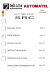
RAID 0 - Data Striping
Data blocks are split into stripes based on the adjusted stripe size (for example, 128 KB)
and the number of hard disks. Each stripe is stored on a separate hard disk. Significant
improvement of the data throughput is achieved using this RAID level, especially with
sequential read and write. RAID 0 includes no redundancy. When one hard disk fails, all
data is lost.
Figure 1-1. RAID 0 - Data Striping
1.3.2
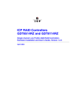
RAID 1 - Disk Mirroring/Disk Duplexing
All data is stored twice on two identical hard disks. When one hard disk fails, all data is
immediately available on the other without any impact on performance and data integrity.
With Disk Mirroring (Figure 1-2) two hard disks are mirrored on one I/O channel. If each
hard disk is connected to a separate I/O channel, it is called Disk Duplexing (Figure 1-3).
RAID 1 represents an easy and highly efficient solution for data security and system
availability. It is especially suitable for installations which are not too large (the available
capacity is only half of the installed capacity).
Software Installation and User’s Guide
17
Introduction
Figure 1-2. RAID 1 - Disk Mirroring
Figure 1-3. RAID 1 - Disk Duplexing
1.3.3
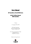
RAID 4 - Data Striping With a Dedicated Parity Drive
RAID 4 works in the same way as RAID 0. The data is striped across the hard disks and
the controller calculates redundancy data (parity information) that is stored on a separate
hard disk (P1, P2, ...). See Figure 1-4. Should one hard disk fail, all data remains fully
available. Missing data is recalculated from existing data and parity information.
Unlike in RAID 1 only the capacity of one hard disk is needed for redundancy. For
example, in a RAID 4 disk array with 5 hard disks, 80% of the installed hard disk capacity
is available as user capacity, only 20% is used for redundancy. In systems with many
small data blocks, the parity hard disk becomes a throughput bottleneck. With large data
blocks, RAID 4 shows significantly improved performance.
18
Software Installation and User’s Guide
Introduction
Figure 1-4. RAID 4 - Data Striping With a Dedicated Parity Drive
1.3.4
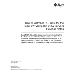
RAID 5 - Data Striping with Striped Parity
Unlike RAID 4, the parity data in a RAID 5 disk array are striped across all hard disks
(Figure 1-5). The RAID 5 disk array delivers a balanced throughput. Even with small data
blocks, which are very likely in a multi-tasking and multi-user environment, the response
time is very good. RAID 5 offers the same level of security as RAID 4. When one hard
disk fails, all data is still fully available. Missing data is recalculated from the existing
data and parity information. RAID 4 and RAID 5 are particularly suitable for systems with
medium to large capacity requirements, due to their efficient ratio of installed and
available capacity.
Figure 1-5. RAID 5 - Data Striping with Striped Parity
1.3.5
RAID 10 - Combination of RAID 1 and RAID 0
RAID 10 is a combination of RAID 0 (Performance) and RAID 1 (Data Security). See
Figure 1-6. Unlike RAID 4 and RAID 5, there is no need to calculate parity information.
RAID 10 disk arrays offer good performance and data security. As in RAID 0, optimum
performance is achieved in highly sequential load situations. Identical to RAID 1, 50% of
the installed capacity is lost through redundancy.
Software Installation and User’s Guide
19
Introduction
Figure 1-6. RAID 10 - Combination of RAID 1 and RAID 0
1.3.6
Levels of Drive Hierarchy Within the Intel® Integrated RAID
Firmware
The IIR firmware is based on four fundamental levels of hierarchy. Each level has its
“own drives” (components). The basic rule is to build up a “drive” on a given level of
hierarchy. The “drives” of the next lower level of hierarchy are used as components.
1.3.6.1
Level 1
Physical drives are hard disks and removable hard disks. Some Magneto Optical (MO)
drives are located on the lowest level. Physical drives are the basic components of all
“drive constructions”. However, before they can be used by the firmware, these hard disks
must be “prepared” through a procedure called initialization. During this initialization
each hard disk receives information which allows an univocal identification even if the
SCSI ID or the controller is changed. For reasons of data coherency, this information is
extremely important for any drive construction consisting of more than one physical drive.
1.3.6.2
Level 2
On the next higher level are the logical drives. Logical drives are introduced to obtain full
independence of the physical coordinates of a physical device. This is necessary to easily
change the IIR controller and the channels, IDs, without loosing the data and the
information on a specific disk array.
20
Software Installation and User’s Guide
Introduction
1.3.6.3
Level 3
On this level of hierarchy, the firmware forms the array drives. Depending on the
firmware installed an array drive can be:
• Single Disks: one disk or a JBOD (just a bunch of drives)
• Chaining sets (concatenation of several hard disks)
• RAID 0 array drives
• RAID 1 array drives, RAID 1 array drives plus a hot fix drive
• RAID 4 array drives, RAID 4 array drives plus a hot fix drive
• RAID 5 array drives, RAID 5 array drives plus a hot fix drive
• RAID 10 array drives, RAID 10 array drives plus a hot fix drive
1.3.6.4
Level 4
On level 4, the firmware forms the host drives. Only these drives can be accessed by the
host operating system of the computer. Drives C, D, etc. under MSDOS etc. are always
referred to as host drives by the firmware. The same applies to NetWare and UNIX drives.
The firmware automatically transforms each newly installed logical drive and array drive
into a host drive. This host drive is then assigned a host drive number which is identical to
its logical drive or array drive number.
The firmware is capable of running several kinds of host drives at the same time. For
example, in MSDOS, drive C is a RAID 5 type host drive (consisting of 5 SCSI hard
disks), drive D is a single hard disk, and drive E is a CD-ROM communicating with IIR
firmware through corelSCSI. On this level the user may split an existing array drive into
several host drives.
After a capacity expansion of a given array drive the added capacity appears as a new host
drive on this level. It can be either used as a separate host drive, or merged with the first
host drive of the array drive. Within RAIDCU, each level of hierarchy has its own menu:
Level 1 - Configure Physical Devices
Level 2 - Configure Logical Drives
Level 3 - Configure Array Drives
Level 4 - Configure Host Drives
Generally, each installation procedure passes through these 4 menus, starting with level 1.
Installation includes the initializing the physical drives, configuring the logical drives,
configuring the array drives (for example, RAID 0, 1, 4, 5 and 10) and configuring the
host drives.
1.4
Transparency of Host Drives
The structure of the host drives installed with StorCon (see Chapter 10, Storage Console)
is not known to the operating system. For example, the operating system does not
recognize that a given host drive consists of a number of hard disks forming a disk array.
Software Installation and User’s Guide
21
Introduction
To the operating system this host drive simply appears as one single hard disk with the
capacity of the disk array. This complete transparency represents the easiest way to
operate disk arrays under the operating system. Neither operating system nor the PCI
computer need to be involved in the administration of these complex disk array
configurations.
1.4.1
Using CD-ROMs, DATs, Tapes, etc.
A SCSI device that is not a SCSI hard disk or a removable hard disk, or that does not
behave like one, is called a Non-Direct Access Device. Such a device is not configured
with StorCon and does not become a logical drive or host drive. SCSI devices of this kind
are either operated through the Advanced SCSI programming Interface (ASPI) (MSDOS
or Novell NetWare), or are directly accessed from the operating system (UNIX).
Note: Hard disks and removable hard disks are called Direct Access Devices. However, there are
some Non-Direct Access Devices, for example, certain MO drives, which can be operated
just like removable hard disks if they have been appropriately configured (for example, by
changing their jumper settings).
22
Software Installation and User’s Guide
Introduction
Software Installation and User’s Guide
23
Getting Started
2
Getting Started
In order to setup the IIR controller, follow the instructions in the sections below to:
• Determine your RAID level and array configuration
• Create a RAID driver installation diskette
• Install the controller
After completing these steps, refer Chapter 3 for quick installation instructions. For more
detailed instructions refer to the other installation chapters (Chapter 4 through Chapter 9).
2.1
Determine the RAID Configuration
Begin the installation by completing the worksheet in Table 2-1 to determine the RAID
level, the number of disk drives, and the disk drive size for your system. Refer to Section
1.3, RAID Levels for more information about RAID levels and to determine the optimum
RAID level solution for your needs.
1. In column 1 of Table 2-1, select a RAID level.
2. In column 2, note the number of disk drives supported for the RAID level you
selected.
3. In column 3, record the number of disk drives you will use for the host drive.
4. In column 4, record the capacity, in megabytes (MB), that you will need on each
physical drive.
You will enter this value as the “Used Capacity per Drive” when you are creating the
host drive. Based on the physical drive capacity value and the number of disk drives
you will use, the RAID configuration software will calculate the total host drive size
for your selected RAID level.
Note: The capacity of the smallest drive in the initial RAID array configuration becomes the
maximum capacity that the RAID configuration software can use for each hard disk in the
host drive. This becomes important when you configure an array with hard disks of
potentially varying sizes and you want to ensure that future drives added to the disk array
will fit in the array (for example, for replacement purposes). Should a new drive have less
24
Software Installation and User’s Guide
Getting Started
than the physical drive capacity used for each disk in the existing disk array, the RAID
configuration software could not accept the new drive.
Caution: The size of the host drive cannot be changed (decreased, increased, or expanded)
once the host drive has been created.
Table 2-1. Pre-installation Worksheet (Creating a Host Drive for the Operating System)
RAID Level
# of disk drives supported
for this RAID level
(minimum to maximum)
RAID 0
2 to 15 per Channel
RAID 1
2
RAID 4
3 to 15 per Channel
RAID 5
3 to 15 per Channel
RAID 10
4 to 15 per Channel 2
Notes and Cautions
2.2
# of disk drives1 to
include in new host
drive
Physical drive
capacity (MB)
2
1. The number of disk drives can not be decreased (only increased via the array
expansion feature) once the host drive is created.
2. RAID 10 only supports an even total number of disk drives. Additional drives are
added in pairs, up to a total of 30 drives over 2 channels.
Create the RAID Driver Installation Diskette
For more information about Linux drivers and updates, see Table 5-3 in Section 5.1.1,
Linux Drivers and Updates.
2.2.1
Preferred Method
The RAID Software Suite CD-ROM is self-booting, assuming that your system supports
booting from the CD-ROM drive.
1. Change your computer’s system BIOS setting so that your system boots from the CDROM. Insert the CD-ROM into the system CD-ROM drive and power up the system.
The ROM-DOS Startup Menu appears (Figure 2-7).
Software Installation and User’s Guide
25
Getting Started
Figure 2-7. ROM-DOS Startup Menu
2. From the menu, select Make Diskettes, press <Enter>. The Select a Type of Diskette to
Create screen appears. See Figure 2-8.
Figure 2-8. Select a Type of Diskette to Create
3. Press <Enter> to select OS Diskettes. The Select an OS to Create screen appears. See
Figure 2-9.
Figure 2-9. Select an OS to Create
4. Highlight the OS to be installed and press <Enter>.
26
Software Installation and User’s Guide
Getting Started
5. Select the specific OS to be installed and press <Enter>.
6. A DOS screen will appear. Follow the instructions to extract the image to diskette.
After the diskette is created, the Select an OS to Create screen appears (Figure 2-9).
7. Remove the diskette from the floppy drive and set it aside. You will be instructed
when to use it during the OS installation.
8. In the Select an OS to Create screen select Main Menu. The Select a Type of Diskette
to Create screen appears (Figure 2-8).
9. Select Exit & Reboot to reboot the system.
10. Change your computer’s system BIOS setting so that your system boots normally (not
from the CD-ROM).
2.2.2
Alternative Methods
If you are unable to create the IIR controller installation diskette by using the method
described in Section 2.2.1, you can create the disk with the following alternative means:
• If you have a Windows 2000 or Windows NT server, you can use the RAID Software
Suite CD-ROM on the Windows server to generate an IIR controller driver diskette for
any of its supported operating systems (see Section 2.2.2.1).
• If you do not have a Windows server, you can manually create the diskette for the
following operating systems
— SCO OpenServer (see Section 2.2.2.2)
— SCO UnixWare (see Section 2.2.2.3)
2.2.2.1
Create IIR Driver for Any Supported OS using a Windows Server
Use the RAID Software Suite CD-ROM on a Windows 2000 or Windows NT server to
generate an IIR controller driver diskette for any supported OS.
1. Insert the RAID Software Suite CD-ROM into the CD-ROM drive of the Windows
server.
2. DemoShield* starts automatically and displays the Intel® Integrated RAID splash
screen (see Figure 2-10). If DemoShield does not start automatically, then run the
following file from the CD-ROM drive: <CD-ROM root>\autorun.exe
Software Installation and User’s Guide
27
Getting Started
Figure 2-10. Intel® Integrated RAID Splash Screen
3. Click OS Diskettes. The Select an Operating System screen appears (see Figure 2-11).
Select the appropriate operating system of the system into which you will install the
IIR controller.
Figure 2-11. Select an Operating System Screen
4. Select the screen options that are appropriate for your specific operating system
version.
5. A command prompt window appears requesting that you insert a formatted floppy
diskette.
6. Insert the floppy in the floppy drive and press Enter. The command prompt window
closes automatically after the diskette has been written.
7. Exit the DemoShield by pressing <Esc> or clicking on the window’s Close icon (the
‘X’ at the upper right corner of Figure 2-11).
28
Software Installation and User’s Guide
Getting Started
2.2.2.2
Create OpenServer IIR Driver
1. On a OpenServer system, insert the RAID Software Suite CD-ROM and go to the apps
folder.
2. Create a folder on the system hard drive and copy the rawrite.exe application to that
folder.
3. Open the Opensv5x folder on the CD-ROM, then open the dskimg folder.
4. Copy sco5x.img to the folder created in step 2.
5. Open a command window. From the command prompt, go to the folder created in step
2 and type the following command: “rawrite”.
6. Enter the file name: sco5x.img.
7. Insert a blank floppy diskette in the drive and follow the instructions on screen.
2.2.2.3
Create SCO UnixWare IIR Driver
1. On a SCO UnixWare server, insert the RAID Software Suite CD-ROM and go to the
apps folder.
2. Create a folder on the system hard drive and copy the rawrite.exe application to that
folder.
3. Open the unixware folder on the CD-ROM, then open the dskimg folder.
4. Copy unixw7.img to the folder created in step 2.
5. Open the command window. From the command prompt, go to the folder created in
step 2 and type the following command: “rawrite”.
6. Enter the file name: “unixw7.img” and the floppy drive name (usually “a:”).
7. Insert a blank floppy diskette in the drive and follow instructions on screen.
2.3
Install the IIR Controller
Refer to the Hardware Guide for the detailed installation procedure for your IIR
controller.
Warning: SHOCK HAZARDS may be present inside the unit in which this card is being installed.
Disconnect all power cords to the unit before removal of any covers. Follow the warnings
noted in your computer’s user or service manual before installing this board. ONLY after all
the covers are reinstalled should you reconnect the power cords and power up the computer
for the software installation and use.
1. Power off the computer, disconnect power cord(s) and remove the system cover
(consult the documentation that came with your computer system).
2. Install the IIR controller into an available PCI slot that is applicable for the product
(refer to the accompanying Hardware Guide for more details).
3. Connect cables. If using SCSI, ensure that the end of the SCSI bus is properly
terminated. Consult the accompanying Hardware Guide for cable and SCSI bus
termination details.
Software Installation and User’s Guide
29
Getting Started
4. If the IIR controller is configured with removable SDRAM, be sure that the DIMM is
installed in the adapter prior to use. Ensure that the optional battery backup is
disconnected during any installation or removal of the DIMM. Not all adapters are
configured with removable SDRAM or battery backup support. For installation details
and applicability to your IIR controller, refer to the Hardware Guide.
5. Replace the system cover and reconnect power cord(s).
After installing the adapter, go to the appropriate operating system chapter for your needs
to continue the installation.
30
Software Installation and User’s Guide
Quick Installation
3
Quick Installation
This chapter covers the quick installation of the IIR controller hardware and software on a
newly created bootable host drive with the following operating systems:
• Microsoft Windows 2000
• Microsoft Windows NT 4.0
• Novell NetWare 4.2x, 5.x and 6.x
• SCO UnixWare 7.1.1 and 8.0
Refer to Chapter 4, Chapter 6 and Chapter 7 for more complex installations on these same
operating systems. Refer to Chapter 5, Chapter 8 and Chapter 9 for installations with other
operating systems.
3.1
Roadmap for Quick Installation
Follow the high level steps in Table 3-2 below to complete the quick installation..
d
Table 3-2. High Level Steps for Quick Installation
Step
1. Determine RAID
configuration
2. Create RAID driver
installation diskette
3. Install the IIR
controller
4. Create a bootable host
drive
5. Install the OS onto the
host drive
Reference
See “Determine the RAID Configuration” on page 24.
See “Create the RAID Driver Installation Diskette” on
page 25.
See “Install the IIR Controller” on page 29.
• See “Create a Bootable Host Drive—RAID 1 Mirrored
Array” on page 32.
OR
• See “Create a Bootable Host Drive—RAID 5 Disk
Array with Hot Fix” on page 35.
• See “Microsoft Windows 2000 and Windows NT Quick
Installation” on page 40.
OR
• See “Novell NetWare 4.2x, 5.x and 6.x Quick
Installation” on page 41.
6. Install RAID software
Software Installation and User’s Guide
OR
• See “SCO UnixWare 7.1.1 and 8.0 Quick Installation”
on page 44.
See “RAID Software Suite Quick Installation” on page 45.
31
Quick Installation
3.2
Create a Bootable Host Drive—RAID 1 Mirrored
Array
Storage Console (StorCon) is the software tool used for creating host drives as well as
administering the RAID subsystem. This section describes how to create a bootable host
drive in a RAID 1 mirrored array configuration via the expansion ROM (XROM)
StorCon. See Section 3.3 for an example of a RAID 5 disk array with hot fix drive
configuration.
1. Power on the computer.
2. Press <Crtl>+<g> when the IIR BIOS message appears to load XROM StorCon.
3. Select the controller and press Enter. See Figure 3-12.
Figure 3-12. Select Controller
4. Select the menu option Configure Host Drives and press Enter. See Figure 3-13.
Figure 3-13. Configure Host Drives
32
Software Installation and User’s Guide
Quick Installation
Figure 3-14. Create New Host Drive
5. Select Create new Host Drive (see Figure 3-14) and press Enter. StorCon displays a
list of available hard disks (see Figure 3-15).
6. Use the arrow keys and the Space bar to select two hard disks (these hard disks
become marked with an "*" as shown in Figure 3-15) and press Enter.
Figure 3-15. Select Physical Drive
7. From the Choose Type menu, select RAID 1 and press Enter. See Figure 3-16.
Software Installation and User’s Guide
33
Quick Installation
Figure 3-16. Choose Type Menu
8. StorCon displays a warning that all data on the selected disks will be destroyed (see
Figure 3-17). Confirm your choice by pressing <y>.
Figure 3-17. Host Drive Creation Confirmation
9. StorCon asks for the capacity to use for each drive (see Figure 3-18). Type in the
physical drive capacity that you recorded in Table 2-1 for RAID 1 and press Enter.
Figure 3-18. Drive Capacity
34
Software Installation and User’s Guide
Quick Installation
10. StorCon pauses to determine if you want to configure the selected disks for SAF-TE
Auto Hot Plug. Press <y> or <n> to confirm your choice.
11. StorCon asks if you want to set the host drive type to Cluster. Refer to your product’s
Hardware Guide to determine if clustering is supported before pressing <y> or <n> to
confirm your choice.
12. The new host drive is created (see Figure 3-19). When the build process is completed,
the RAID 1 disk array changes to ready status, for example, the data is fully redundant.
Figure 3-19. Newly Created Host Drive
13. Exit StorCon by pressing <Esc> several times to escape out of the various menus and
pressing <y> to quit.
Follow the instructions in the next section to continue the installation.
3.3
Create a Bootable Host Drive—RAID 5 Disk Array
with Hot Fix
Storage Console (StorCon) is the software tool used for creating host drives as well as
administering the RAID subsystem. This section describes how to create a bootable host
drive in a RAID 1 mirrored array configuration via the expansion ROM (XROM)
StorCon. See Section 3.2 for an example of a RAID 1 mirrored array.
1. Power on the computer.
2. Press <Crtl>+<g> when the IIR BIOS message appears to load XROM StorCon.
Software Installation and User’s Guide
35
Quick Installation
3. Select the controller and press Enter. See Figure 3-20.
Figure 3-20. Select Controller
4. Select the menu option Configure Host Drives and press Enter. See Figure 3-21.
Figure 3-21. Configure Host Drives
36
Software Installation and User’s Guide
Quick Installation
Figure 3-22. Create New Host Drive
5. Select Create new Host Drive (Figure 3-22) and press Enter. StorCon displays a list of
available hard disks (Figure 3-23).
6. Use the arrow keys and the Space bar to select the number of hard disks for your RAID
5 array (minimum of three disks to a maximum of 15 disks per channel). In this RAID
5 + HotFix example, four disks are selected. The selected hard disks become marked
with an "*" as shown in Figure 3-23. Press Enter to accept your selections.
Figure 3-23. Select Physical Drive
Software Installation and User’s Guide
37
Quick Installation
7. From the Choose Type menu, select RAID 5 + HotFix and press Enter. See
Figure 3-24.
Figure 3-24. Choose Type Menu
8. StorCon displays a warning that all data on the selected disks will be destroyed (see
Figure 3-25). Confirm your choice by pressing <y>.
Figure 3-25. Host Drive Creation Confirmation
9. StorCon asks for the capacity to use for each drive (see Figure 3-26). Type in the
physical drive capacity that you recorded in Table 2-1 for RAID 5 and press Enter.
Figure 3-26. Drive Capacity
10. StorCon asks if you want to set the host drive type to ‘Cluster’. Refer to your product’s
Hardware Guide to determine if clustering is supported before pressing <y> or <n> to
confirm your choice.
38
Software Installation and User’s Guide
Quick Installation
The new host drive is created. See Figure 3-27.
Figure 3-27. Newly Created Host Drive
11. Exit StorCon by pressing <Esc> several times to escape out of the various menus and
pressing <y> to quit.
Depending on the size of the host drive, the RAID 5 build process may take a
considerable amount of time. You may exit out of StorCon without waiting for the
build to complete. When leaving StorCon, a progress window informs you about the
estimated completion time for the build process (see Figure 3-28).
Figure 3-28. Progress Window
Upon successful completion of the build process the RAID 5 disk array changes to
ready status, for example, the data is fully redundant.
Software Installation and User’s Guide
39
Quick Installation
You may continue the installation by following the instructions in:
• Section 2.2, Create the RAID Driver Installation Diskette
• Either section 3.4, 3.5, or 3.6, for the applicable OS for your system
• Section 3.7, RAID Software Suite Quick Installation.
3.4
Microsoft Windows 2000 and Windows NT Quick
Installation
This section covers installing the IIR controller and the OS to a host drive for local
administration of the RAID subsystem. For other Windows installation scenarios, see
Chapter 4.
3.4.1
Minimum Requirements
Microsoft Windows 2000
•
•
•
•
RAID Software Suite CD-ROM
9 MB of free hard disk space (for the RAID Software Suite)
Microsoft Windows 2000 Professional†, Server† or Advanced Server†
RAID Software Suite Driver Installation diskette (see Section 2.2 for instructions to
create this diskette)
— One blank high density floppy diskette† may be required to create the installation
diskette
Microsoft Windows NT 4.0
• RAID Software Suite CD-ROM
• 9 MB of free hard disk space (for the RAID Software Suite)
• RAID Software Suite Driver Installation diskette (see Section 2.2 for instructions to
create this diskette)
— One blank high density floppy diskette† may be required to create the installation
diskette
• Microsoft Windows NT 4.0 Workstation†, Server† or Server Enterprise Edition†
† Not supplied
3.4.2
OS Installation Procedures
The following installation procedures highlight the Windows setup options that you must
install during OS installation to successfully prepare the operating system for the
installation of the RAID Software Suite.
40
Software Installation and User’s Guide
Quick Installation
These procedures cover installing the IIR controller and the OS to a host drive for local
administration of the RAID subsystem. For all other installation scenarios, please consult
the accompanying Software Guide.
Install the operating system software using one of the scenarios below which matches
your installation method.
Note: For detailed Windows installation procedures, please consult the documentation that came
with your computer system or operating system.
3.4.2.1
Installing Windows Using the Installation Boot Diskettes
1. Insert the bootable floppy diskette and power on the computer.
2. Let Windows detect the storage devices in your system. When device detection is
complete, press S to specify additional storage devices.
3. Select Other. Insert the RAID Software Suite Driver Installation diskette for Windows
into the floppy drive, press <Enter>.
4. The IIR Controller is automatically selected. Press <Enter>.
5. Complete the text-based portion of the Windows installation procedures. Reboot and
continue with the GUI-based portion of the installation.
6. After the operating system is completely installed, go to Section 3.7 to complete the
installation.
3.4.2.2
Installing Windows Using the Bootable Windows CD-ROM
1. Insert the bootable floppy diskette and power on the computer.
2. Press F6 as soon as the initial blue screen appears to ensure that the RAID Driver
Installation diskette can be loaded when specifying Other.
3. When device detection is complete, press S to specify additional storage devices.
4. Select Other. Insert the RAID Software Suite Driver Installation diskette for Windows
into the floppy drive. Press <Enter>.
5. The IIR Controller is automatically selected. Press <Enter>.
6. Complete the text-based portion of the Windows installation procedures. Reboot and
continue with the GUI-based portion of the installation.
7. After the operating system is completely installed, go to Section 3.7 to complete the
installation.
3.5
Novell NetWare 4.2x, 5.x and 6.x Quick Installation
This section provides quick installation instructions for NetWare. For more detailed
installation instructions or for other installation scenarios, see Chapter 6.
Software Installation and User’s Guide
41
Quick Installation
3.5.1
Minimum Requirements
• RAID Software Suite CD-ROM
• 20 MB of free hard disk space
• RAID Software Suite Driver Installation Diskette for NetWare (see Section 2.2 for
instructions to create this diskette).
— One blank high density floppy diskette† may be required to create the installation
diskette
• Novell NetWare 4.2x† or 5.x† software
† Not supplied
3.5.2
OS Installation Procedures
3.5.2.1
New Installation of NetWare 4.20 with the SRCRX.HAM Driver
1. Create a driver diskette from the RAID Software Suite CD-ROM. See Section 2.2 for
details to create this disk.
2. Start the OS installation from the NetWare CD-ROM. (NetWare 4.2x CD-ROMs are
NOT bootable so you must have a bootable DOS partition installed on your target hard
drive and have the appropriate DOS driver for your CD-ROM.)
3. At the driver summary menu select modify drivers.
4. Insert the driver diskette into drive A:
5. Press <Enter> on the IIR driver list.
6. Press <Insert> in the IIR controller driver menu.
7. Press <F3> and change the path to A:\DRIVERS\4XX then press <Enter>.
8. Select the SRCRX.HAM driver and complete the installation.
3.5.2.2
New Installation of NetWare 5.0 with the SRCRX.HAM Driver
Important: The SRCRX.HAM driver depends on a later version of the NWPA.NLM than
was shipped on the NetWare 5.0 CD. Without the NWPA.NLM update, the
SRCRX.HAM driver will fail to load. The following procedure will allow you to upgrade
the NWPA.NLM on the fly during OS installation.
1. Create a driver diskette from the RAID Software Suite CD-ROM. See Section 2.2 for
details to create this disk.
2. Start the OS installation from the NetWare bootable CD-ROM.
3. The NetWare installation will eventually load a "Welcome" screen asking you to
verify the startup directory (C:\NWSERVER).
4. Press <Alt>+<F10> to exit the installation.
5. At the NetWare console prompt, type "down" and press Enter (the installation exits to
the boot drive's DOS prompt).
42
Software Installation and User’s Guide
Quick Installation
6. Insert the driver diskette into drive A:.
7. If your NetWare startup directory is drive C:, then run
A:\INSTALL\NWUPDATE.BAT, otherwise create a subdirectory named
NWUPDATE at the root of your boot drive and copy all the files from
A:\DRIVERS\5XX to the NWUPDATE subdirectory.
8. Leave the NetWare 5.0 bootable CD in place, but remove the driver diskette from
drive A:.
9. Reboot the server. After rebooting the server, the NetWare 5.0 Install will start again.
10. Right after the Accept the License Agreement screen, select the "Continue with
Existing Partition" option.
Note: If you chose to install a "New Server," you may encounter the following warning dialog
box:
“Warning: A previously installed version of NetWare was detected in
C:\NWSERVER. If you choose to install a new server, all data on the existing server
will be lost. <Press ENTER to continue>”.
If the warning dialog box appears, press Enter.
11. Complete the installation.
3.5.2.3
New Installation of NetWare 5.1x with the SRCRX.HAM Driver
1. Create a driver diskette from the RAID Software Suite CD-ROM. See Section 2.2 for
details to create this disk.
2. Start the OS installation from the NetWare bootable CD-ROM.
3. At the storage driver summary menu select modify drivers.
4. Insert the driver diskette into drive A:
5. Press <Enter> on the storage driver list.
6. Press <Insert> in the storage controller driver menu.
7. Press <F3> and change the path to A:\DRIVERS\5XX then press <Enter>.
8. Select the SRCRX.HAM driver.
9. Complete the installation.
3.5.2.4
New Installation of NetWare 6.x with the SRCRX.HAM Driver
1. Start the OS installation from the NetWare bootable CD-ROM. The SRCRX.HAM
driver is on the NetWare 6.x CD and is installed automatically if a RAID controller is
detected.
2. After installing the operating system, install all patches and updates from Novell and
update the SCSRX.HAM driver. For information on updating the SCSRX.HAM
driver, refer to the Software Guide.
Software Installation and User’s Guide
43
Quick Installation
3.6
SCO UnixWare 7.1.1 and 8.0 Quick Installation
This section provides quick installation instructions for UnixWare. For more detailed
installation instructions or for other installation scenarios, see Chapter 7.
3.6.1
Minimum Requirements
• RAID Software Suite CD-ROM
• 20 MB of free hard disk space
• RAID Software Suite Driver Installation diskette for UnixWare (see Section 2.2 for
instructions to create this diskette).
— One blank high density floppy diskette† may be required to create the installation
diskette
• SCO UnixWare 7.1.1 or 8.0 OS software†
† Not supplied
3.6.2
OS Installation Procedures
Note: When installing SCO UnixWare, create only one RAID device (host drive) on which the
operating system is to be installed.
1. Create and configure one RAID device from the BIOS of IIR Storage Console
(accessed by pressing <Ctrl>+<g>).
2. Insert the UnixWare installation diskette 1 of 2 which was included with your OS
user’s manual. Installation begins.
During installation, UnixWare prompts you to insert a Host Bus Adapter (HBA)
diskette. Insert the RAID Software Suite Driver Installation diskette. If you do not
have the diskette for the operating system that you are installing, then create it before
continuing. See Section 2.2 for instructions to create this disk.
3. During the installation of UnixWare 7.11 (this does not apply to UnixWare 8.0), you
will be prompted to install the Network Information Services (NIS) package. By
default the installation will configure your system as an NIS client. See your system
administrator for configuration of the NIS services.
Note: Installation of this service may take an extended period of time.
If you do not plan on using the NIS or there is not an NIS server present on your
network that you are installing this system onto, defer installation of NIS at this time
by pressing <F8> at the NIS configuration screen.
44
Software Installation and User’s Guide
Quick Installation
3.7
RAID Software Suite Quick Installation
3.7.1
Microsoft Windows 2000 and NT 4.0
1. Log into Windows using a user account with administrative rights.
2. Insert the RAID Software Suite CD-ROM in the CD-ROM drive. When the Intel®
Integrated RAID splash screen (see Figure 3-29) appears, click on the link Install, to
launch the Setup program.
Note: If the RAID Software Setup Splash Screen does not appear, then run the setup.exe file that
resides at:
<CD-ROM root>\windows\install\setup.exe
Figure 3-29. RAID Software Setup Splash Screen
3. A welcome screen appears. Click Next.
4. License Agreement - Click Yes after reading to agree.
5. Setup Type - Select one of the following for Local or Remote administration of the IIR
controller (see Figure 3-30) and click Next:
— Server (Utilities, Services and Drivers)
This option allows for local administration of the IIR controller.
— Client (Remote Utilities only)
Software Installation and User’s Guide
45
Quick Installation
This option allows for remote administration of the IIR controller.
Figure 3-30. Setup Type
6. Choose the default selections (recommended) or select components that you wish to
install. Click Next to continue the installation.
7. Choose the Destination Location - Use the default directory for installation, click Next.
8. Select the Program Folder - Use default Program Group, click Next.
9. After the file copy completes, click to complete the installation. Restart the computer
after you install the device drivers.
This completes the installation procedure for Windows.
3.7.2
Novell NetWare 4.2x, 5.x and 6.x
3.7.2.1
Installing the IIR Controller Tools Kit Package
Note: StorCon.NLM will not find any controllers unless SRCRX.HAM is already loaded and
running.
1. Select Product options, then Install a product not listed.
2. Change the path to A:\INSTALL and press <Enter> to continue.
3. Select Storage RAID Controller Tools Kit (StorCon.NLM) by setting the cursor on its
menu item and pressing the space bar (an X will appear in the item's checkbox).
4. Press <F10> to accept the selected item.
5. NetWare will copy the necessary files, automatically load StorCon.NLM, and modify
the AUTOEXEC.NCF file to load StorCon.NLM for each subsequent restart of the
server.
46
Software Installation and User’s Guide
Quick Installation
3.7.2.2
Configuring Tools for Remote Access
1. Create a group SRC_Operator in the NDS.
2. Add the Admin and all other users who will use this interface.
3. Load SRCIPX.NLM.
4. Start Storage Console (StorCon.exe) or Storage Console Plus (StorCon+.exe) from a
workstation using a user name of the group SRC_Operator and his/her NetWare
password.
3.7.3
SCO UnixWare 7.1.1 or 8.0
No additional steps are necessary to install the RAID Software Suite once you have
completed the installation described in Section 3.6.
Software Installation and User’s Guide
47
Installing Microsoft Windows 2000, Windows XP Professional or Windows NT
Installing Microsoft Windows 2000,
Windows XP Professional or Windows NT
4
This section covers installation issues related to the Microsoft Windows 2000, Windows
XP Professional, and Windows NT operating systems. For a successful installation, study
your specific Operating System manuals thoroughly. The required drivers described in
this section can be created from the RAID Software Suite CD-ROM.
4.1
Operating System Installation Procedures
Note: Begin the installation process in this chapter if you are installing the OS and the IIR
controller or upgrading from the Windows NT OS (the OS is currently installed on a
compatible IIR controller) to Windows 2000.
Your installation falls into one of two categories:
• Install the OS on either a host drive or single disk that is attached to and configured on
the IIR controller that you are installing (see Section 4.1.2), or
• Install the OS on either an IDE hard disk or a SCSI hard disk that is not attached to the
IIR controller that you are installing (see Section 4.1.3)
4.1.1
Pre-Installation Requirements Checklist
4.1.1.1
Minimum Hardware Requirements
For detailed hardware requirements, specifications, and installation procedures specific to
your IIR controller, consult the Hardware Guide.
4.1.1.2
Computer System Requirements
•
•
•
•
•
4.1.1.3
Computer with CD-ROM Drive
One available PCI slot
IIR controller
PCI 2.2 compliant system BIOS
SCSI hard disk drives (the minimum needed to meet desired RAID level requirements)
Minimum Software Requirements
Microsoft Windows 2000
• RAID Software Suite CD-ROM
• 9 MB of free hard disk space (for the RAID Software Suite)
48
Software Installation and User’s Guide
Installing Microsoft Windows 2000, Windows XP Professional or Windows NT
• Microsoft Windows 2000 Professional†, Server† or Advanced Server†
• RAID Software Suite Driver Installation diskette (Miniport diskette for Windows
2000)
— One blank high density floppy diskette† may be required to create the installation
diskette
Microsoft Windows NT 4.0
• RAID Software Suite CD-ROM
• 9 MB of free hard disk space (for the RAID Software Suite)
• RAID Software Suite Driver Installation diskette (Miniport diskette for Windows NT
4.0)
— One blank high density floppy diskette† may be required to create the installation
diskette
• Microsoft Windows NT 4.0 Workstation†, Server† or Server Enterprise Edition†
Microsoft Windows XP Professional
•
•
•
•
RAID Software Suite CD-ROM
9 MB of free hard disk space (for the RAID Software Suite)
Microsoft Windows XP Professional†
RAID Software Suite Driver Installation diskette (Miniport diskette for Windows XP
Professional)
— One blank high density floppy diskette may be required to create the installation
diskette
† Not supplied
4.1.2
Installing an Operating System onto a Host Drive
Ensure that you have completed the steps described in Chapter 2, “Getting Started,”
before continuing with the installation of the OS onto a host drive.
4.1.2.1
Create a Host Drive
Refer to the Quick Start Guide or Chapter 10, “Storage Console,” for details on using the
expansion ROM version of Storage Console to create a host drive.
After creating the host drive, follow the steps in the next section to continue the
installation.
4.1.2.2
Windows 2000 / XP Professional / NT 4.0 Installation Procedures
Note: This document, when referring to Windows 2000, Windows XP and Windows NT,
applies to the following Windows operating systems unless otherwise noted:
• Windows 2000 Server, Advanced Server, and Professional
Software Installation and User’s Guide
49
Installing Microsoft Windows 2000, Windows XP Professional or Windows NT
• Windows XP Professional
• Windows NT 4.0 Server, Enterprise Edition, Terminal Server Edition, and Workstation
4.1.2.3
Installing the OS
The following procedures highlight the Windows setup options that you must install
during OS installation to successfully prepare the operating system for the installation of
the RAID Software Suite.
Install the operating system software using one of the scenarios below which matches
your installation method.
Note: For detailed Windows installation procedures, please consult the documentation that came
with your computer system or operating system.
Installing Windows Using the Installation Boot Diskettes
1. Insert the first bootable floppy diskette and power on the computer.
2. Let Windows detect the storage devices in your system. When device detection is
complete, press S to specify additional storage devices.
Note: For Windows XP, skip steps 3 and 4 and proceed to step 5.
3. Select Other. Insert the RAID Software Suite Driver Installation diskette for Windows
into the floppy drive, press <Enter>.
4. The IIR controller is automatically selected. Press <Enter>. Press <Enter> again to
continue installation.
5. Follow the on-screen instructions to complete the text-based portion of the Windows
installation procedures. Reboot and follow the on-screen instructions to continue with
the GUI-based portion of the installation.
6. After the operating system is completely installed, go to Section 10.2, Installing and
Launching StorCon to complete the installation.
Installing Windows Using the Bootable Windows CD-ROM
1. Boot your computer to the CD-ROM of your Windows OS.
2. Press F6 key as soon as the initial blue screen appears to load the RAID drivers. Note:
If installing Windows XP, after having pressed F6, be sure NOT to press F2 when
prompted.
3. When prompted press S and insert the IIR controller Installation diskette and press
Enter indicate diskette is ready then press Enter again to select RAID Controller.
When indicated, press Enter a third to continue Windows OS installation.
4. Follow on-screen prompts to complete the text-based portion of the installation and an
auto-reboot will occur to continue the GUI portion of your Windows OS installation.
DO NOT touch any key if prompted to boot from the CD-ROM. Let the computer boot
to the hard drive to continue the installation. When the GUI portion of setup completes
the computer will auto-reboot. If it does not auto-reboot, manually reboot the computer
to continue the installation.
50
Software Installation and User’s Guide
Installing Microsoft Windows 2000, Windows XP Professional or Windows NT
Note: As of this writing, this software package had not passed Windows Logo testing for
Windows XP. However, certification is anticipated in the very near future. As a result, a
window may appear notifying you about the Windows Logo testing compatibility. You
can simply click on Yes when prompted to continue your installation.
5. After the operating system is completely installed, go to Section 10.2, Installing and
Launching StorCon to complete the installation.
4.1.3
Installing an OS onto an IDE or SCSI Disk Drive not Attached to
the IIR Controller
4.1.3.1
Windows 2000 / XP Professional / NT 4.0 Installation Procedures
Note: This document, when referring to Windows 2000 and Windows NT, applies to the
following Windows operating systems:
• Windows 2000 Server, Advanced Server, and Professional
• Windows XP Professional
• Windows NT 4.0 Server, Enterprise Edition, Terminal Server Edition, and Workstation
Installing the Operating System
The following procedures highlight the Windows setup options that you must install to
successfully prepare the operating system for the installation of the RAID Software Suite.
Note: For detailed Windows installation procedures, please consult the documentation that came
with your computer system or operating system.
Install the operating system software using one of the scenarios below that matches your
installation method.
Installing Windows with Installation Boot Diskettes
Booting from Windows installation diskettes initially to setup Windows.
1. Ensure that your computer is bootable from the floppy disk drive. Insert the first boot
diskette and power up your system. Insert additional diskettes as required by on-screen
instructions. This process will load the correct driver to access you non-bootable CDROM drive.
2. Go to step 2 of the following section.
Installing Windows Using the Bootable Windows CD-ROM
Note: If the driver for your disk drive controller is on the Windows CD-ROM, then follow
prompts and then continue the installation at Section 10.2, Installing and Launching
StorCon.
If you are installing a driver that does not come with the Windows installation CD-ROM,
for example, the IIR controller driver created in Section 2.2, then follow the procedure
below.
Software Installation and User’s Guide
51
Installing Microsoft Windows 2000, Windows XP Professional or Windows NT
1. Insert CD-ROM and power up your system.
2. If the drivers for your disk drive controller are not on the bootable Windows CDROM, Press F6 as soon as the initial blue screen appears to ensure that the driver
diskette can be loaded.
Note: When installing Windows XP Professional, after having pressed F6, do not press F2
unless you are attempting an Automated System Recovery (ASR)
3. After installing the OS, continue the IIR controller installation at Section 10.2,
Installing and Launching StorCon.
4.1.4
Upgrading/Replacing Windows NT 4.0 Server Currently
Installed on a Host Drive or Single Disk
4.1.4.1
Before you Begin
• If you are replacing and existing IIR controller with another, ensure that the OS is
installed on an IIR controller that is compatible (see the accompanying Hardware
Guide) with the new OS and/or RAID Software Suite that you are about to install. If it
is compatible, then continue with Section 4.1.4.2 to install Windows 2000 or
Section 4.1.4.3 to install Windows XP. If not, then exit this installation procedure.
• Windows NT4.0 Server is not 'upgradeable' to Windows XP Professional. The
procedure described in Section 4.1.4.3 will 'replace' the existing NT 4.0 Server
installation.
Warning: Installation of Windows XP Professional using this procedure will overwrite all data
on this host drive.
4.1.4.2
Upgrading Windows NT 4.0 to Windows 2000
Note: For hardware installation details, consult the accompanying Hardware Guide.
1. Before beginning, back up any vital data.
2. If you are not installing a new adapter and you are only upgrading the OS and the
RAID software, go to step 9.
3. If you are installing a new IIR controller, and transferring your OS to that new adapter,
go to step 4.
4. Power off your computer, disconnect all power cords, and remove the computer's
cover to access the motherboard.
5. Disconnect the SCSI cable(s), if applicable.
6. Remove the currently installed IIR controller and insert the new IIR controller into the
same slot.
7. Connect the SCSI cable, if applicable, to the newly installed IIR controller.
8. Replace the computer's cover, reconnect all power cords, and reboot the computer.
9. Log into NT with administrative user rights.
52
Software Installation and User’s Guide
Installing Microsoft Windows 2000, Windows XP Professional or Windows NT
10. Insert the Windows 2000 CD-ROM. The Windows 2000 upgrade utility will autostart. Click Yes to start the upgrade.
11. When Welcome to the Windows 2000 Setup Wizard launches, select Upgrade to
Windows 2000 and complete this portion of the upgrade. Windows should auto-reboot.
If not, manually reboot the computer.
12. Leave the Windows 2000 CD-ROM in the CD-ROM drive and let the computer boot
up. DO NOT touch any key when prompted to boot from the CD-ROM. Let the
computer boot to the hard drive to continue the upgrade.
13. When the computer gets to the first blue setup screen, immediately press the F6 key to
load the RAID drivers for Windows 2000.
14. When prompted press S and insert the IIR controller Installation diskette and continue
the Windows 2000 upgrade.
15. Setup will complete the text-based portion of the installation and auto-reboot to
continue the GUI portion of the Windows 2000 Upgrade.
16. When the GUI portion of setup completes, the computer will auto-reboot. If it does not
auto-reboot, manually reboot the computer to continue the upgrade.
17. Go to Section 4.1.5 to complete the upgrade.
4.1.4.3
Replacing existing Windows NT 4.0 with Windows XP Professional
Note: For hardware installation details, consult the accompanying Hardware Guide.
1. Before beginning, back up any vital data.
Warning: Installation of Windows XP Professional using this procedure will overwrite all data
on this host drive.
2. If you are not installing a new adapter and you are only upgrading the OS and the
RAID software, go to step 9.
3. If you are installing a new IIR controller, and transferring your OS to that new adapter,
go to step 4.
4. Power off your computer, disconnect all power cords, and remove the computer's
cover to access the motherboard.
5. Disconnect the SCSI cable(s), if applicable.
6. Remove the currently installed IIR controller and insert the new IIR controller into the
same slot.
7. Connect the SCSI cable, if applicable, to the newly installed IIR controller.
8. Replace the computer's cover, reconnect all power cords, and reboot the computer.
9. Log into NT with administrative user rights.
10. Insert the Windows XP Professional CD-ROM. The Welcome to Windows XP wizard
window appears. Click on Install Windows XP to start the installation.
11. A Windows Setup window will appear informing you that a Windows NT server to
Windows XP 'upgrade' is not possible. Click on OK to continue.
Software Installation and User’s Guide
53
Installing Microsoft Windows 2000, Windows XP Professional or Windows NT
12. A new Welcome to Windows Setup window appears. Ensure that Installation type is
New Installation. Be sure to read and understand all the information provided in this
window then click Next to continue.
13. Read and understand the license agreement then click on I accept this agreement. Click
on Next to continue.
14. Enter the product license key as indicated and click on Next to continue.
15. The Setup Options window appears. Click on Next to accept defaults. The computer
will now reboot.
16. Leave the Windows XP Professional CD-ROM in the CD-ROM drive and let the
computer boot up. DO NOT touch any key if prompted to boot from the CD-ROM. Let
the computer boot to the hard drive to continue the installation.
17. When the computer gets to the first blue setup screen, immediately press the F6 key to
load the RAID drivers for Windows XP Professional. After having pressed F6, be sure
NOT to press F2 when prompted.
18. When prompted press S and insert the IIR controller Installation diskette and press
Enter indicate diskette is ready then press Enter again to select RAID Controller.
When indicated, press Enter a third to continue Windows XP installation.
19. Follow on-screen prompts to complete the text-based portion of the installation and an
auto-reboot will occur to continue the GUI portion of the Windows XP Professional
installation. DO NOT touch any key if prompted to boot from the CD-ROM. Let the
computer boot to the hard drive to continue the installation.
20. When the GUI portion of setup completes the computer will auto-reboot. If it does not
auto-reboot, manually reboot the computer to continue the installation.
21. Go to Section 4.1.5 to complete the installation.
4.1.5
Installation to an Existing OS
This section covers all installations of the IIR controller into computers with existing
(previously installed) operating systems.
Ensure that you have completed the steps described in Chapter 2, “Getting Started,”
before continuing with the installation of the IIR controller to an existing OS.
4.1.5.1
Minimum Requirements
•
•
•
•
•
Fully functional OS already installed and running on the computer.
Administrative level privilege on the computer.
Hard Disk Space: 9 MB Minimum
Driver installation diskette
Installed IIR controller. See the accompanying Hardware Guide for installation details.
Once all these requirements are met and you are logged on to the computer, continue to
Section 4.1.5.2.
54
Software Installation and User’s Guide
Installing Microsoft Windows 2000, Windows XP Professional or Windows NT
4.1.5.2
Installing Drivers for your IIR Controller
Method 1 (Preferred)
Follow the instructions for installing the drivers, tools and utilities in Section 10.2,
Installing and Launching StorCon.
Method 2 (Alternative)
1. Insert the RAID Software Suite CD-ROM in CD-ROM drive.
2. DemoShield starts automatically. If DemoShield does not start automatically, then run
the following file from the CD-ROM drive: <CD-ROM root>\autorun.exe
3. Click OS Diskettes, then click on Windows. Select the appropriate Windows version.
4. A command prompt window appears requesting that you insert a formatted floppy
diskette.
5. Insert the floppy in the floppy drive and press Enter. The command prompt window
closes automatically after the diskette has been written.
6. Use the OS to find the IIR controller and install its driver. Follow the instructions
below for the applicable OS.
Windows 2000
a. Open the Device Manager and scan the PCI bus for new hardware or hardware
changes.
b. Select the IIR controller in the ‘hardware found’ list, and then click Next.
c. Select Search for a suitable driver for my device, and then click Next.
d. Select Floppy Drive.
e. Click on Next and follow the instructions up to and including system reboot.
Windows NT
a. Open the Control Panel, SCSI Adapters.
b.
c.
d.
e.
Click the Drivers tab and click the Add button.
Insert the driver disk in the floppy drive.
Click Have Disk. Navigate to the floppy drive and click OK.
Select RAID Controller and click OK. Follow the instructions up to and including
system reboot.
Windows XP Professional
a. Open the Device Manager and scan the PCI bus for new hardware or hardware
changes.
b. Select the IIR controller in the `hardware found' list, and then click Next. Note: If
the IIR controller is the only new device found, the 'Found New Hardware
Wizard' window will appear.
c. Select 'Install from a list or specific location', and then click Next.
d. Select 'Search removable media', then click Next
Software Installation and User’s Guide
55
Installing Microsoft Windows 2000, Windows XP Professional or Windows NT
Note: As of this writing, this software package had not passed Windows Logo testing for
Windows XP. However, certification is anticipated in the very near future. As a result, a
window may appear notifying you about the Windows Logo testing compatibility. You
can simply click on 'Continue Anyway' to complete your software installation.
e. Click on Finish to complete your installation.
7. Go to Section 10.2, Installing and Launching StorCon to install the tools and utilities
of the RAID Software Suite.
4.1.6
Swapping Out / Replacing Compatible IIR Controllers in
Windows 2000 and Windows XP Professional
The procedure for replacing an IIR controller with another compatible but different model
is different depending on where the operating system is installed. See Section 4.1.6.1 if
the operating system is installed on a host drive connected to the IIR controller or
Section 4.1.6.2 if the operating system is installed on an IDE drive connected to the
motherboard.
For a list of compatible IIR controllers, see the Hardware Guide.
4.1.6.1
If OS Is on a Host Drive Connected to the IIR Controller
If Windows OS is installed to a host drive connected to the IIR controller, then replacing
an IIR controller with another compatible but different model is similar to the procedure
for adding a new controller. The important distinction is that you add the new IIR
controller into the system first, before removing the old controller.
Caution: If you do not install the new host adapter first, it may result in a Windows OS boot
failure.
To swap compatible IIR controllers, follow these steps:
1. Power down your computer.
2. Insert the new (compatible) IIR controller into an available PCI slot, leaving the
existing IIR controller intact.
3. Power up your computer. Your Windows OS should load up as normal and detect the
new IIR controller. Install the Windows OS driver if prompted to. If a driver install
Wizard starts, follow the same driver installation procedures as in the User's Manual.
4. Reboot if prompted.
5. Once the new IIR controller is functioning properly, power down your computer.
6. Remove the old IIR controller (leave the new IIR controller in the slot that it was
initially installed in and detected by your Windows OS) and move all desired devices
to the new adapter.
7. All attached devices should be recognized upon reboot.
56
Software Installation and User’s Guide
Installing Microsoft Windows 2000, Windows XP Professional or Windows NT
4.1.6.2
If OS is on an IDE Drive Connected to the Motherboard
If Windows OS is installed to an IDE drive connected to the motherboard, you have two
options for replacing an IIR controller with another compatible but different model:
Option 1 (Recommended)
1. Uninstall the Raid Software Suite.
2. Shut down the system and replace the RAID controller.
3. Boot to Windows OS and follow the procedure for installing a Raid Controller to an
existing operating system. See Section 4.1.5.
Option 2
1. Shut down the system and replace RAID controller.
2. Boot to Windows OS.
3. When the Found New Hardware Wizard appears, follow the steps in the wizard and
point it to the following locations when prompted:
• c:\winnt\inf for inf file location
• c:\winnt\system32\drivers for raidsrc.sys driver.
Note: 'winnt' may be substituted for 'windows' depending on how your OS was installed.
4.2
Configuring the RAID Configuration Service
The RAID Configuration Service (RCS) must be configured to allow for remote
management of the RAID subsystem of your controller. The following steps describe how
to configure the RCS.
1. Open the Control Panel on your Windows Desktop. Double-click the RAID
Configuration Service icon.
Software Installation and User’s Guide
57
Installing Microsoft Windows 2000, Windows XP Professional or Windows NT
2. The RAID Configuration Service window appears. Click the Account Manager tab.
See Figure 4-31 below.
Figure 4-31. Access Account Manager
3. The Account Manager window displays. See Figure 4-32 below.
58
Software Installation and User’s Guide
Installing Microsoft Windows 2000, Windows XP Professional or Windows NT
Figure 4-32. Enter User Account and Password
4. Enter a user name and password. This will be the account used to manage the RAID
subsystem remotely on this computer.
5. Click the ‘full’ Access radio button.
6. Click Add. Note that the account has been added to the list on the right side of the
window. You can add additional accounts if desired, but at this point the configuration
is complete.
7. Click OK to close the window and save changes. See Figure 4-33.
Software Installation and User’s Guide
59
Installing Microsoft Windows 2000, Windows XP Professional or Windows NT
Figure 4-33. Confirm User Account and Password
60
Software Installation and User’s Guide
Installing Linux
5
Installing Linux
This section discusses installation issues related to the Linux operating systems (SCO*,
Debian*, DLD*, LST*, Red Hat* and SuSE*). For a successful installation, study the
Linux system manuals thoroughly. The required drivers can be created from the RAID
Software Suite CD-ROM.
5.1
Before you begin
Ensure that you have completed the steps described in Chapter 2, “Getting Started,”
before beginning the installation described in this chapter.
5.1.1
Linux Drivers and Updates
In some cases, you must make a driver diskette from the CD-ROM before you begin the
Linux installation to a RAID drive. In other cases, you can use the driver provided by the
Linux distributor to install the operating system and then update the driver to the latest
version using the source code that is available on the CD-ROM. To determine which case
applies to your operating system, see Table 5-3 below.
Linux drivers and updates are available on the CD-ROM in the following location:
<CD>:\linux\dskimg\
Table 5-3. Driver Diskette or Driver Update
Linux Version
Make Driver
Diskette
Before Installation
Update
Driver After
Installation
Red Hat 6.2, 7.0, 7.1 and 7.2
Yes
No
SuSe 7.3 and 8.0
No
Yes
Mandrake 8.1 and 8.2
No
Yes
Caldera 3.1
Yes
No
Debian 2.2r3 and 2.2r6
Yes
No
TurboLinux 6.5 and 7.0
Yes
No
Software Installation and User’s Guide
61
Installing Linux
5.1.2
5.1.3
Available Drivers and Tools on the RAID Software Suite CDROM
gdth.tgz
IIR driver sources for Intel and alpha systems
StorCon-2.02.gz
StorCon for i386 systems, version 2.02
srcd-1.10-suse.tgz
Remote RAID Configuration Service, version 1.10, with start/
stop script for SuSE Linux
srcd-1.10-redhat.tgz
Remote RAID Configuration Service, version 1.10, with start/
stop script for Red Hat Linux
Assumptions About Path Names
Since the user may have received StorCon on the CD-ROM or as a download from the
web, and because Linux administrators may mount volumes with a variety of names,
certain assumptions were made in this document.
Table 5-4. Linux Path Names
Path Names
/mnt/cdrom
$
/dev/hda
Note
If the Linux driver and StorCon is not being installed from the
CD-ROM, the /mnt/cdrom part of the path may be changed to
the proper directory
Assumes this is your current directory level.
Path entries such as the example on the right are assumptions
and may be changed to match what the administrator has
selected for the particular system.
5.2
General Installation Notes
5.2.1
Minimum Hardware Requirements
For detailed hardware requirements, specifications, and installation procedures specific to
your IIR controller, consult the Hardware Guide for this adapter.
5.2.1.1
Computer System Requirements
•
•
•
•
•
62
Computer with CD-ROM Drive (not attached to the IIR controller)
One available PCI slot
IIR controller
PCI 2.2 compliant system BIOS
SCSI hard disk drives (the minimum needed to meet desired RAID level requirements)
Software Installation and User’s Guide
Installing Linux
Note: If the IIR controller is configured with removable SDRAM, be sure that the DIMM is
installed in the adapter prior to use. (Ensure that the optional battery backup is
disconnected during any installation or removal of the DIMM). Not all adapters are
configured with removable SDRAM or battery backup support. For installation details
and applicability to your IIR controller, consult the Hardware Guide for this adapter.
5.2.1.2
Minimum Software Requirements
• RAID Software Suite CD-ROM
• 10 MB of hard disk space
• RAID Driver Installation Diskette for Linux (see Section 2.2, Create the RAID Driver
•
•
•
•
5.3
Installation Diskette for instructions)
Linux Updates Diskette (if required)
Linux Kernel Support (open source)
Linux Red Hat 7.x Installation CD-ROMs
Root access on the Linux server
Installing Red Hat Linux 7.x on a Host Drive
To install Red Hat Linux 7.x on to a host drive, first create the appropriate driver disk
from the RAID Software Suite CD-ROM. Follow the procedure below.
1. Ensure that you have completed the steps described in Chapter 2, “Getting Started,”
before beginning the OS installation.
2. Ensure the IIR controller is installed in your machine and is connected to drives on
which you intend to create a host drive.
3. Boot your machine and when prompted press <Ctrl>+<G> to enter StorCon. Create a
single host drive from your selected disks.
For more information on creating host drives using the StorCon, see Section 10.4.1.1,
Create New Host Drive.
Read the Red Hat documentation to understand the disk space/size requirements for
the Red Hat 7.x installation.
Note: Refer to the Red Hat Installation Manual before proceeding.
4. Ensure that the system is set to boot from the CD-ROM drive and boot to the Red Hat
7.x CD-ROM. At the boot prompt type linux dd, or if you have an updates diskette,
type linux dd updates. Press <Enter> to continue.
Note: An updates diskette is required for installation of Red Hat 7.2 to a RAID Host Drive.
5. The installer will prompt for a driver disk. Insert the driver diskette created in the
previous procedure and press <Enter>. (To create a driver disk see Section 2.2, Create
the RAID Driver Installation Diskette).
6. If you typed linux dd updates in step 4, the installer will prompt you for an
updates diskette. Insert the updates diskette and press <Enter>.
Software Installation and User’s Guide
63
Installing Linux
7. Follow onscreen instructions to complete your installation. Upon completion, remove
the floppy diskette from the drive and reboot the system.
5.4
Installing an IIR Controller onto an Existing Linux
Server
5.4.1
Installation of Driver Sources from the RAID Software Suite CDROM
The same procedure can be used for updating a currently installed IIR GDTH driver using
the driver sources.
1. If you are installing the driver sources from the RAID Software Suite CD-ROM, and if
InstallShield* has not started automatically, place the RAID Software Suite CD-ROM
in the CD-ROM drive and use the following procedure:
a. Mount the CD-ROM by typing the following command:
$ mount /dev/cdrom /mnt/cdrom
b. Copy the driver sources to /usr/src/linux/drivers/scsi
c. Enter the following command:
$ cp /mnt/cdrom/linux/drivers/gdth.tgz /usr/src/linux/
drivers/scsi**
d. Unpack and unzip the tar file using the following command:
$ tar -zxvf /usr/src/linux/drivers/scsi/gdth.tgz
**Linux kernel versions are specific. For example, the directory /usr/src/linux-2.4.2 is
specific to Linux kernel version 2.4.2 found in Red Hat version 7.1. You should be aware of
the specific path for your distribution.
Note:
2. Compile a new kernel with module support and GDTH SCSI support enabled. This
procedure depends on the Linux distribution. make config, make dep, make clean may
be necessary to install the host drive. Refer to your specific Linux distribution
documentation for help.
3. Compile the modules. This procedure depends on the Linux distribution. Refer to your
specific Linux distribution documentation for help.
4. Configure Lilo.conf to use the new module support. This procedure depends on the
Linux distribution. Refer to your specific Linux distribution documentation for help.
64
Software Installation and User’s Guide
Installing Linux
5.5
GDT Driver Parameters
5.5.1
Reservation of SCSI Devices
The reservation of SCSI devices becomes necessary if you want Direct Access Devices
(for example, hard disks, removable hard disks like Iomega or SyQuest) to be directly
controlled by Linux and not the IIR controller's firmware (for example, they are not
configured as host drives).
Reservation of SCSI devices is also called raw-service. In this case the IIR controller does
not cache the data to/from the reserved SCSI device. This reservation is important for
removable hard disks. If they are controlled by the IIR controller and are a host drive, a
media change is very difficult.
Non Direct Access Devices like CD-ROMs, Streamers, DATs, etc. do NOT require a
reservation.
Important: The reservation of SCSI devices is only possible with not-initialized SCSI
devices. (Use StorCon to de-initialize an already initialized device).
1. From driver version 1.10 on you can add the parameters for the reservation with the
LILO append command:
Excerpt of /etc/lilo.conf:
# End LILO global section
# Linux bootable partition config begins
image = /boot/vmlinuz
root = /dev/sda2
label = Linux
append = "gdth=reserve_list:1,0,6,0"
# Linux bootable partition config ends
This gdth driver parameter reserves the SCSI device that is connected with IIR
controller 1 (the second IIR controller), SCSI Bus 0 (channel A), ID 6, LUN 0 for
Linux (raw service).
After each change in /etc/lilo.conf lilo must be loaded once.
Driver parameters may also be entered at the LILO boot prompt. (for example:
gdth=reserve_list:1,0,6,0).
Software Installation and User’s Guide
65
Installing Linux
5.5.2
Further Driver Parameters
irq1,irq2, etc.
Only for RAID EISA controllers with disabled BIOS (irq1,
irq2, etc. correspond with the IRQs of the RAID controllers)
disable:Y
deactivates the RAID driver
disable:N
activates the RAID driver
reserve_mode:0
reserves no SCSI devices [*1]
reserve_mode:1
reserves all not-initialized removable hard disk [*1]
reserve_mode:2
reserves all not-initialized SCSI devices [*1]
reserve_list:h,b,t,l,h,b,t,l,... reserves SCSI devices at the corresponding coordinates with
h=Hostadapter, b=SCSI Bus, t=Target ID, l=LUN
reverse_scan:Y
reversed scanning order of the PCI controllers
reverse_scan:N
Normal scanning order of PCI controllers according to the
system BIOS
max_ids:x
x = number of target IDs per SCSI channel (accelerates the
boot process)
rescan:Y
rescan all SCSI channels / Ids
rescan:N
scan only those SCSI devices found during system power up
[*1]
• [*1] The driver parameters reserve_mode and rescan:N require IIR controllers with
•
•
•
•
firmware version FW x.23.00 or higher.
The current default settings of the driver are:
‘gdth=disable:N,reserve_mode:1,reverse_scan:N,max_ids:127,rescan:N’
If gdth is loaded as a module, these parameters can also be added with a special syntax.
IRQ parameters are entered as ‘IRQ=’ (for example, IRQ=10). Several parameters are
not separated with a comma (‘,’) but a space (‘ ‘). All ‘:’ are substituted with ‘=’, all ‘Y’
with ‘1’ and all ‘N’ with ‘0’.
Default: ‘modprobe gdth disable=0 reserve_mode=1 reverse_scan=0 max_ids=127
rescan=0’
5.6
Installation of StorCon Monitoring Utility
5.6.1
Installation of StorCon from the RAID Software Suite CD-ROM
1. If you are installing the StorCon from the RAID Software Suite CD-ROM, then place
the RAID Software Suite CD-ROM in the CD-ROM drive and mount the CD-ROM:
$ mount /dev/cdrom /mnt/cdrom
66
Software Installation and User’s Guide
Installing Linux
2. Copy the StorCon utility archive to /usr/sbin. Note that x.xx in these examples is the
version of StorCon that was shipped on your software CD that matches the current
Firmware.
$ cp /mnt/cdrom/linux/install/storcon-2.02.gz /usr/sbin/storcon-x.xx
3. Unpack the archive file and rename:
$ gunzip -d /usr/sbin/storcon-x.xx.gz
$ mv /usr/sbin/storcon-x.xx /usr/sbin/storcon
5.6.2
Using StorCon Monitoring Utility
To use StorCon a gdth driver version 1.26 or higher is required. To check the current gdth
driver version type:
$ grep Driver /proc/scsi/gdth/0 (where 0 represents the controller
number)
To run the StorCon utility, type ‘StorCon’ at any prompt. Select the interface (Linux if
locally run, TCP/IP sockets if remote).
Note: While using StorCon from the Linux system console, the StorCon screen may be
overwritten by system/kernel log messages. To avoid this, execute the following
command (entered at the prompt from a console session):
dmesg -n 1
When finished using StorCon, the console log level can be set back to the default level
using the following command:
dmesg -n 7
This behavior is not observed if the StorCon utility is used from an X-windows terminal
window.
5.7
Remote Monitoring with the Intel SRCD Remote
Access Service
srcd is the remote access service for IIR controllers. With srcd running, you can manage
disk arrays from a remote workstation using storage management software (for example,
StorCon) via TCP/IP.
Configure /etc/srcd.conf to send SNMP traps or execute an external program (for
example, mail) when a disk array controller event occurs. See comments in /etc/
srcd.conf for details.
Software Installation and User’s Guide
67
Installing Linux
5.7.1
SRCD Installation Instructions from the RAID Software Suite
CD-ROM
1. Copy the srcd archive to /etc (may be srcd-1.10-suse.tgz or srcd-1.10-redhat.tgz)
$ cp /mnt/cdrom/linux/install/srcd-v.vv-xxxx.tgz /etc/srcdv.vv-xxxx.tgz
2. Unpack srcd-v.vv-xxxx.tgz:
$ tar xvfz srcd-v.vv-xxxx.tgz
3. Run install.sh. It will interactively set up a start script and a file /etc/
srcd.conf:
$ ./install.sh
4. Edit /etc/srcd.conf to send SNMP traps or execute an external program when
controller events occur.
5. If srcd is not running, start it by executing one of the following commands:
— For SuSE-Linux: $ /sbin/init.d/srcd start
— For RedHat-Linux: $ /etc/rc.d/rc2.d/srcd start
68
Software Installation and User’s Guide
Installing Linux
Software Installation and User’s Guide
69
Installing Novell NetWare
6
Installing Novell NetWare
This section discusses installation issues related to the Novell NetWare operating system
and covers versions NetWare 4.2x , NetWare 5.x and NetWare 6.x. For a successful
installation, study the NetWare system manuals thoroughly. The information provided in
this section refers to the loading of the IIR NetWare driver(s) only. The required drivers
can be created from the RAID Software Suite CD-ROM.
6.1
Pre-Installation Requirements Checklist
This section identifies the minimum hardware and software required to successfully
install the IIR controller and the accompanying RAID Software Suite. Ensure that you
have completed the steps described in Chapter 2, “Getting Started,” before beginning the
installation described in this chapter.
6.1.1
Minimum Hardware Requirements
For detailed hardware requirements, specifications, and installation procedures specific to
your IIR controller, consult the Hardware Guide.
6.1.1.1
Computer System Requirements
•
•
•
•
•
Computer with CD-ROM Drive (not attached to the IIR controller)
One available PCI slot
IIR controller
PCI 2.2 compliant system BIOS
SCSI hard disk drives (the minimum needed to meet desired RAID level requirements)
Note: If the IIR controller is configured with removable SDRAM, be sure that the DIMM is
installed in the adapter prior to use. (Ensure that the optional battery backup is
disconnected during any installation or removal of the DIMM). Not all adapters are
configured with removable SDRAM or battery backup support. For installation details
and applicability to your IIR controller, consult the Hardware Guide.
6.1.2
Minimum Software Requirements
• RAID Software Suite CD-ROM
• 20 MB of free hard disk space
• RAID Software Suite Driver Installation Diskette for NetWare (see Section 2.2, Create
the RAID Driver Installation Diskette for instructions).
— One blank high density floppy diskette† may be required to create the installation
diskette
70
Software Installation and User’s Guide
Installing Novell NetWare
• Novell NetWare 4.2x, 5.xx or 6.x software†
† Not supplied
6.2
New installation of NetWare 4.2x, 5.xx and 6.x
The following procedures assume that your IIR controller(s) is (are) already installed in
your system. If you plan to install the OS to a host drive, you must first configure the host
drive through the expansion ROM (XROM) version of Storage Console. At system boot
time, press <Ctrl>+<G> when prompted to invoke the XROM version of Storage
Console.
Note: Install all Novell patches and updates prior to installing the IIR controller driver and
Storage Console. These updates can be found at <http://www.novell.com>.
6.2.1
New Installation of NetWare 4.20 with the SRCRX.HAM Driver
1. Create a driver diskette from the RAID Software Suite CD-ROM. See Section 2.2,
Create the RAID Driver Installation Diskette for instructions.
2. Start the OS installation from the NetWare CD-ROM. (NetWare 4.2x CD-ROMs are
NOT bootable so you must have a bootable DOS partition installed on your target hard
drive and have the appropriate DOS driver for your CD-ROM.)
3. At the driver summary menu select modify drivers.
4. Insert the driver diskette into drive A:
5. Press <Enter> on the IIR driver list.
6. Press <Insert> in the IIR controller driver menu.
7. Press <F3> and change the path to A:\DRIVERS\4XX then press <Enter>.
8. Select the SRCRX.HAM driver and complete the installation.
Note: The above procedure will only install the device drivers for your controller. The IIR
controller Tools Kit (Storage Console) is installed separately. See Section 6.3.2 for
details.
6.2.2
New Installation of NetWare 5.0 with the SRCRX.HAM Driver
Important: The SRCRX.HAM driver depends on a later version of the NWPA.NLM than
was shipped on the NetWare 5.0 CD. Without the NWPA.NLM update, the
SRCRX.HAM driver will fail to load. The following procedure will allow you to upgrade
the NWPA.NLM on the fly during OS installation.
1. Create a driver diskette from the RAID Software Suite CD-ROM. See Section 2.1 for
details to create this disk.
2. Start the OS installation from the NetWare bootable CD-ROM.
Software Installation and User’s Guide
71
Installing Novell NetWare
3. The NetWare installation will eventually load a "Welcome" screen asking you to
verify the startup directory (C:\NWSERVER).
4. Press <Alt>+<F10> to exit the installation.
5. At the NetWare console prompt, type "down" and press Enter (the installation exits to
the boot drive's DOS prompt).
6. Insert the driver diskette into drive A:.
7. If your NetWare startup directory is drive C:, then run
A:\INSTALL\NWUPDATE.BAT, otherwise create a subdirectory named
NWUPDATE at the root of your boot drive and copy all the files from
A:\DRIVERS\5XX to the NWUPDATE subdirectory.
8. Leave the NetWare 5.0 bootable CD in place, but remove the driver diskette from
drive A:.
9. Reboot the server. After rebooting the server, the NetWare 5.0 Install will start again.
10. Right after the Accept the License Agreement screen, select the "Continue with
Existing Partition" option.
Note: If you chose to install a "New Server," you may encounter the following warning dialog
box:
"Warning: A previously installed version of NetWare was detected in
C:\NWSERVER. If you choose to install a new server, all data on the existing server
will be lost. <Press ENTER to continue>"
If the warning dialog box appears, press Enter.
11. Complete the installation.
Note: The above procedure will only install the device drivers for your controller. The IIR
controller Tools Kit (Storage Console) is installed separately. See Section 6.3.2 for
details.
6.2.3
New Installation of NetWare 5.1x with the SRCRX.HAM Driver
1. Create a driver diskette from the RAID Software Suite CD-ROM. See Section 2.2,
Create the RAID Driver Installation Diskette for instructions.
2. Start the OS installation from the NetWare bootable CD-ROM.
3. At the storage driver summary menu select modify drivers.
4. Insert the driver diskette into drive A:
5. Press <Enter> on the storage adapter list.
6. Press <Insert> twice from the storage controller driver menu.
7. Press <F3> and change the path to A:\DRIVERS\5XX then press <Enter>.
8. Select the SRCRX.HAM driver.
9. Complete the installation.
72
Software Installation and User’s Guide
Installing Novell NetWare
Note: The above procedure will only install the device drivers for your controller. The IIR
controller Tools Kit (Storage Console) is installed separately. See Section 6.3.2 for
details.
6.2.4
New Installation of NetWare 6.x with the SRCRX.HAM Driver
1. Start the OS installation from the NetWare bootable CD-ROM. The SRCRX.HAM
driver is on the NetWare 6.x CD and is installed automatically if a RAID controller is
detected.
2. After installing the operating system, install all patches and updates from Novell and
update the SRCRX.HAM driver. For information on updating the SCSRX.HAM
driver, see Section 6.3.
Note: The above procedure will only install the device drivers for your controller. The IIR
controller Tools Kit (Storage Console) is installed separately. See Section 6.3.2 for
details.
6.3
Adding Drivers and/or Storage Console to an
existing NetWare Installation
The following procedures assume that the IIR controller(s) is (are) already installed in
your system.
Install all Novell patches and updates prior to installing the IIR controller driver and
Storage Console. These updates can be found at <http://www.novell.com>.
1. Create a driver diskette from the RAID Software Suite CD-ROM. See Section 2.2,
Create the RAID Driver Installation Diskette for instructions.
2. Power on the system and boot to the OS.
3. Load the Netware Configuration Options tool:
• NetWare 4.2x—Load INSTALL.NLM.
• NetWare 5.x and above—Load NWCONFIG.NLM.
4. Insert the driver diskette into drive A:
5. Complete Section 6.3.1 and/or Section 6.3.2 to install your desired packages.
• NetWare 4.2x and 5.xx—Complete Section 6.3.2. to install the IIR Controller Tools Kit
Package. You do not need to reinstall the driver package if you initially installed the driver
from a driver diskette that you created from the CD.
• NetWare 6.x—Complete Section 6.3.1 to update the SRCRX.HAM driver that was
installed from the NetWare 6.x CD and complete Section 6.3.2 to install the IIR Controller
Tools Kit Package.
6.3.1
Installing the IIR Driver Package
1. Select Product options, then Install a product not listed.
Software Installation and User’s Guide
73
Installing Novell NetWare
2. Change the path to A:\INSTALL and press <Enter> to continue.
3. Select Storage RAID Controller Driver (SRCRX.HAM) by setting the cursor on its
menu item and pressing the space bar (an X will appear in the item's check box).
4. Press <F10> to accept the selected item.
5. After the file copy is complete, select Return to previous menu to get back to the
INSTALL/NWCONFIG main options
6. Select Driver Options.
7. Select Configure disk and storage device drivers.
8. Select Discover and load additional drivers.
9. Press Enter to continue past any module load errors not related to the IIR controller.
10. Press <F3> to continue past any non-IIR controller related hardware found by
NetWare for which a matching driver was not found.
11. NetWare will now load the SRCRX.HAM driver for each hardware instance you
added in the system and update the STARTUP.NCF file so the driver will load for
each subsequent restart of the server.
12. Select Return to previous menu twice to get back to the INSTALL/NWCONFIG main
options.
6.3.2
Installing the IIR Controller Tools Kit Package
Note: StorCon.NLM will not find any controllers unless SRCRX.HAM is already loaded and
running.
1. Select Product options, then Install a product not listed.
2. Press F3 to change the path to A:\INSTALL and press <Enter> to continue.
3. Select Storage RAID Controller Tools Kit (StorCon.NLM) by setting the cursor on its
menu item and pressing the space bar (an X will appear in the item's check box).
4. Press <F10> to accept the selected item.
NetWare will copy the necessary files, automatically load StorCon.NLM, and modify
the AUTOEXEC.NCF file to load StorCon.NLM for each subsequent restart of the
server.
5. Exit the Configuration Options tool.
6.3.2.1
Configuring Tools for Remote Access
1. Create a group SRC_Operator in the NDS.
2. Add the Admin and all other users who will use this interface.
3. Load SRCIPX.NLM.
4. Start Storage Console (StorCon.exe) or Storage Console Plus (StorCon+.exe) from a
workstation using a user name of the group SRC_Operator and his/her NetWare
password.
74
Software Installation and User’s Guide
Installing Novell NetWare
6.4
ASPI Support for NetWare 4.2x, 5.x
You will need to ensure that the file NWASPI.CDM is in the server’s search path. For
NetWare 4.2, NWASPI.CDM is already located in the server’s startup directory
(C:\NWSERVER) so no action is required. For NetWare 5.x, copy NWASPI.CDM into
the server’s startup directory from C:\NWSERVER\DRIVERS.
Note: Since the debut of Media Manager (MM.NLM) and the NetWare Peripheral Architecture
(NWPA.NLM), the need for ASPI in NetWare is rare. However, there may be a few
applications that require ASPI. Unless your application(s) require it, do not install ASPI.
This procedure describes how to manually install Novell’s ASPI manager module, but be
aware that you may need to follow specific instructions from your application vendor to
correctly configure ASPI.
1. With the server loaded and running, load INSTALL.NLM (NetWare 4.2x) or
NWCONFIG.NLM (NetWare 5.x).
2. Select NCF Files Option from the main menu.
3. Select Edit Startup.ncf.
4. Add the following line at the end of the .CDM section of STARTUP.NCF:
5. LOAD NWASPI.CDM
6. Reboot the server.
6.5
Tips and Tricks
6.5.1
Optimize Data Throughput
High performance RAID controllers are designed for multi-I/O operations and are capable
of processing several I/Os simultaneously. Cache controllers with powerful on-board
RISC CPUs can handle many I/Os per second. NetWare offers the option of adjusting the
number of write I/Os which are loaded on the mass storage subsystem. To gain optimum
performance and speed from modern high performance disk controllers, the amount of the
so-called maximum concurrent disk cache writes has been increased with every further
development of NetWare. Looking back to NetWare 3.11, only 100 concurrent disk cache
writes were possible. With NetWare 4.10, it can be as much as 1000.
The number of concurrent disk cache writes delivering the best performance is highly
dependent on the performance of the installed disk controller, the amount of cache RAM
on the controller and the hard disks. The IIR controllers can easily cope with up to 500
simultaneous requests. The following command line enables the adjustment of a new
number under NetWare (default value = 50):
set maximum concurrent disk cache writes = xxxx
where xxxx represents the required number of concurrent disk cache writes.
Software Installation and User’s Guide
75
Installing Novell NetWare
6.5.2
'Cache Memory Allocator Out of Available Memory' in PCI-ISA
Systems
PCI systems which are not equipped with an EISA Bus behave in the same way as an ISA
mainboard with regard to the available RAM memory. NetWare therefore does not
automatically recognize the available memory above 16 MByte. The command
register memory allows the registration of memory above 16 MByte. Memory
shortage can appear while loading several applications simultaneously on the server,
especially where large volumes are concerned. This is because the register memory
command is normally carried out in the autoexec.ncf file. This is usually located in the
SYS volume. An autoexec.ncf file placed in the DOS partition of the NetWare Server
helps to get around this problem. To carry out this process, the disk driver must be
removed from the startup.ncf and inserted into the autoexec.ncf in the DOS partition.
After completing this process, the disk driver must be loaded directly after the register
memory command as indicated in the following autoexec.ncf file example.
register memory 1000000 1000000
LOAD C:SRCRP312
....
An additional start file can be loaded on the SYS volume for differentiation, for example,
with the name 'autonet.ncf'.
6.5.3
Installing NetWare 4.1 - Wrong Drive Name
The following problem often occurs when installing NetWare 4.1 server. While copying
the module cdrom.nlm, the system hangs. This problem only occur when the CD-ROM
drive's name under the OS from which it is copied is 'cdrom'. For example, the config.sys/
autoexec.bat contains the following files:
DEVICE=aspicd.sys /D:cdrom
and
mscdex /D:cdrom
To avoid this problem, change the CD-ROM's OS name to another name. For example,
use
/D:scsicd' instead of '/D:cdrom
6.5.4
NetWare-Server Not Stable When Under High Utilization
High server utilization combined with a large number of applications running on the
server can lead to an increase in the number of dirty cache buffers resulting in an unstable
server. To avoid this situation, modify the following parameters.
76
Software Installation and User’s Guide
Installing Novell NetWare
• Increase the number of concurrent disk cache writes for the disk subsystem. Set
maximum concurrent disk cache writes. This parameter can be increased up to 500 for
high performance controllers and fast hard disks.
• Decrease the delayed write standard parameter. Set dirty disk cache delay time. This
parameter sets the time where dirty buffers are written (flushed) from the cache of
NetWare to the hard disk. The minimum value is 0.8 seconds. Care should be taken not
to go below 0.8 seconds because this value influences server performance substantially.
6.5.5
IIR and Non-ASPI Compatible Controllers
If an IIR controller is operated under NetWare together with another controller/host
adapter which does not support the ASPI standard, SCSI raw devices cannot be operated
on both controllers (tapes, CD-ROMs).
In general, NetWare gives preference to controllers which support the ASPI Standard (for
example, IIR controllers, Adaptec*). As soon as aspitran.dsk is loaded (auto-loading
module) tapes and CD-ROMs on the ASPI non-compatible controller are no longer
recognized. To avoid this problem, the file aspitran.dsk can be deactivated via a
modification.
To deactivate aspitran.dsk, find the string 'ASPI_Entry' by using a Disk-Monitor in
aspitran.dsk (please pay attention to upper case letters etc). Modify the string by replacing
'A' with an 'X' (for example, 'XSPI_Entry'). The modified aspitran.dsk enables the
operation of raw devices on non-ASPI-compatible controllers.
Note: After this modification, no other raw devices (tapes, CD-ROMs) are recognized on the IIR
controller or Adaptec.
6.5.6
Last Status Information
All IIR controllers temporarily store the status information from all hard disks that are
connected to that controller. This information can be useful when searching for possible
causes of disk failures or interferences. The last status information consists of a
hexadecimal, 8 digit number and can be displayed via the StorCon or saved in a Save
Information ASCII file. The information is temporarily available in the IIR controller's
RAM. Therefore, it is important to check this information before switching off and before
carrying out a Reset if a disk failure has occurred or if interference was present. The last
status information is divided into controller-specific and SCSI-specific messages. A
detailed description can be found in the file laststat.pdf.
6.5.7
Adding Additional Capacity after an Online Capacity Expansion
The additional capacity resulting from an online capacity expansion of an existing array
drive is introduced to the system as a new host drive. To be able to make use of the new
capacity without having to down the server, type “scan for new devices” on the server
console to recognize the new capacity. Use Install to build new partitions and volumes.
Software Installation and User’s Guide
77
Installing Novell NetWare
6.6
Notes on ARCserve
Make sure that you always have the latest version of your ARCserve software.
The back-up program ARCserve can be used in connection with the IIR controller. The
communication between the tape device (for example, DAT, DLT) and the IIR controller
takes place through the ASPI interface. For this purpose, the IIR ASPI Manager
aspitran.dsk is needed. When loading the regular IIR NetWare driver (for example,
srcrp311.dsk), the ASPI Manager is automatically loaded, too. During the installation of
ARCserve, choose Adaptec ASPI Manager as the interface.
78
Software Installation and User’s Guide
Installing SCO UnixWare
Installing SCO UnixWare
7
This section discusses installation issues related to the SCO UnixWare operating systems
(UnixWare 7.1.1 and UnixWare 8.0). For a successful installation, study the SCO system
manuals thoroughly. The required drivers can be created from the RAID Software Suite
CD-ROM.
7.1
General Installation Notes
This section identifies the minimum hardware and software required to successfully
install the IIR controller with the accompanying RAID Software Suite. Ensure that you
have completed the steps described in Chapter 2, “Getting Started,” before beginning the
installation described in this chapter.
7.1.1
Minimum Hardware Requirements
For detailed hardware requirements, specifications, and installation procedures specific to
your IIR controller, consult the Hardware Guide.
7.1.1.1
Computer System Requirements
•
•
•
•
•
Computer with CD-ROM Drive (not attached to the IIR controller)
One available PCI slot
IIR controller
PCI 2.2 compliant system BIOS
SCSI hard disk drives (the minimum needed to meet desired RAID level requirements)
Note: If the IIR controller is configured with removable SDRAM, be sure that the DIMM is
installed in the adapter prior to use. (Ensure that the optional battery backup is
disconnected during any installation or removal of the DIMM). Not all adapters are
configured with removable SDRAM or battery backup support. For installation details
and applicability to your IIR controller, consult the Hardware Guide.
7.1.2
Minimum Software Requirements
• RAID Software Suite CD-ROM
• 20 MB of free hard disk space
• RAID Software Suite Driver Installation diskette for UnixWare (see Section 2.2,
Create the RAID Driver Installation Diskette for instructions).
— One blank high density floppy diskette† may be required to create the installation
diskette
• SCO UnixWare 7.1.1 or 8.0† OS software
Software Installation and User’s Guide
79
Installing SCO UnixWare
† Not supplied
7.2
Installing the IIR Controller as Boot Controller
There must be a host drive on the first IIR controller found during a cold boot. In addition,
the IIR BIOS must be enabled and the SCSI ID of the corresponding IIR SCSI channel
must be set to 7.
To begin the installation
1. Boot the system with the first UnixWare boot disk or CD. The operating system scans
the system for host adapters.
2. When requested insert the UnixWare HBA-Disk.
3. Follow the installation as described in the SCO documentation.
Note: The assignment of an IRQ to an INT is made by the PCI System BIOS. UnixWare
versions 2.x and higher automatically recognize the IRQ of a PCI expansion card.
7.3
Installing the IIR Controller as an Additional
Controller
Two cases are discussed below.
7.3.1
No IIR Controller Has Yet Been Configured
In this case, the IIR driver must be installed from the UnixWare HBA-Disk by means of
the UnixWare desktop and the options “System Setup”, “Application Setup”.
Alternatively, this procedure can be carried out from the UnixWare shell: “pkgadd -d /dev/
dsk/f0t” (IIR driver disk in drive 0).
80
Software Installation and User’s Guide
Installing SCO UnixWare
7.3.2
An IIR Controller Has Already Been Configured
This procedure is different depending on the operating system:
If using UnixWare 7.11
In this case, you only have to add an additional entry for the new IIR controller. This is
carried out by the command
/etc/scsi/pdiadd -d DRQ -v IRQ -m MEM srch
For DRQ use 0 (not necessary for PCI boards). For IRQ write the IRQ number that IIR
controller uses. MEM corresponds to the DPMEM address of the IIR controller (which is
displayed in the BIOS message of the IIR controller after power up). In both cases, you
have to carry out a cold boot to use the new IIR controller under UnixWare.
Example: /etc/scsi/pdiadd -d 0 -v 12 -m c8000 srch.
Then reboot the UnixWare system. No kernel link is required because the driver will be
dynamically loaded.
If using UnixWare 8.0
UnixWare 8.0 automatically detects the new device at startup, reboots the system and
links the driver.
7.4
Installing an Operating System onto a Host Drive or
Single Disk
Note: When installing UnixWare, create only one RAID device (host drive) on which the
operating system is to be installed.
1. Create and configure one RAID device from the BIOS of Storage Console (accessed
by pressing <Ctrl>+<G>).
2. Insert UnixWare installation diskette 1 of 2 which was included with your OS user’s
manual. Installation begins.
During the installation UnixWare prompts you to insert a Host Bus Adapter (HBA)
diskette. Insert the RAID Software Suite Driver Installation diskette. If you do not
have the diskette for the operating system that you are installing, then create it before
continuing. See Section 2.2, Create the RAID Driver Installation Diskette for
instructions.
3. This step does not apply to UnixWare 8.0. During the installation of UnixWare, you
will be prompted to install the Network Information Services (NIS) package. By
default the installation will configure your system as an NIS client. See your system
administrator for configuration of the NIS services.
Software Installation and User’s Guide
81
Installing SCO UnixWare
Note: Installation of this service may take an extended period of time.
If you do not plan on using the NIS or there is not an NIS server present on your
network that you are installing this system onto, defer installation of NIS at this time
by pressing <F8> at the NIS configuration screen.
4. After completing the OS installation, proceed to Section 7.5 to complete the
installation.
7.5
Hardware Identifiers of SCSI Devices
7.5.1
Host adapter Number (HA)
The host adapter number assigned to the IIR controller is derived from the PCI slot
number of the IIR controller. Therefore, if there is only one IIR controller installed in the
PCI bus computer system, the host adapter number is 0. If there are two IIR controllers
installed, the IIR controller with the lower PCI Slot number is assigned host adapter
number 0 and the IIR controller with the higher PCI slot number is assigned host adapter
1.
Note: After a cold boot, the IIR BIOS displays a couple of messages, each beginning with the
controller’s PCI slot number, for example, “[PCI 0/3] 4 MB RAM detected”. The number
after the ‘/’ is the slot number of the controller. This will help determine the order of the
IIR controllers and which host adapter number is assigned to them by UnixWare.
7.5.2
Bus Number, Target ID and LUN
Target IDs and LUNs for “Non-Direct Access Devices” (devices like streamers, tapes and
CD-ROMs and therefore not configurable via StorCon), are directly assigned to the SCSI
ID and the channel of the IIR controller. Host drives are assigned to the SCSI ID by their
Host Drive number on a virtual channel. This virtual channel is added to the physical
channels. On a 2-channel controller the bus number of this channel is 2.
7.5.2.1
Configuration Example (1st channel = 0, 2nd = 1, virtual =2)
In the PCI computer are two IIR controllers (HA 0 = 1st IIR controller, HA 1 = 2nd IIR
controller), each with two SCSI channels.
1 hard disk
as host drive no. 0 on HA0
1 hard disk
as host drive no. 0 on HA1
1 hard disk
as host drive no. 1 on HA1
1 Streamer
SCSI ID 2, LUN 0 on SCSI channel A of HA0
1 CD-ROM
SCSI ID 3, LUN 0 on SCSI channel B of HA0
1 DAT
SCSI ID 2, LUN 0 on SCSI channel A of HA1
82
Software Installation and User’s Guide
Installing SCO UnixWare
The resulting HA, Bus, Target ID and LUN are indicated in Table 7-5.
Table 7-5. Bus Number, Target ID and LUN
7.6
HA
Bus
Target ID
LUN
Device
0
2
0
0
1st hard disk, host drive no. 0 (boot drive)
0
0
2
0
Streamer
0
1
3
0
CD-ROM
1
2
0
0
hard disk, host drive no. 0
1
2
1
0
hard disk, host drive no. 1
1
0
2
0
DAT
1
2
2
0
hard disk, host drive no.2
Additional Information
• After creating a new Host Drive use /sbin/sdiadd to rescan the SCSI bus and to
recognize the new drive. Then you can use diskadd utility to partition the drive and
create the file system. To add a second drive, diskadd can be run with the following
command line:
/etc/diskadd -F s5dm 1
To determine the parameters for diskadd, run /sbin/sdiconfig -l which will produce
output similar to:
0:0,7,0:
0,3,0:
1,7,0:
2,0,0:
2,4,0:
1:0,2,0:
0,0,0:
HBA :
HBA :
HBA :
DRIVE
DRIVE
HBA :
CDROM
(srch,1) SRC SCSI
nStor nexStor 8Le 1.030020
(srch,1) SRC SCSI
: Host Drive #00
equal to c0b2t0d0
: Host Drive #04
equal to c0b2t4d0
(ide,1) Generic IDE/ATAPI
: LITEON CD-ROM LTN483 BL1F
To run diskadd on a host drive, find the corresponding "Disk Name" of the host drive to
be mounted. For example, to mount Host Drive #00, the command would be /etc/
diskadd c0b2t0d0.
• When using Direct Access Devices with exchangeable media (for example, removable
hard disks) that are not reserved for the raw service, media has to be inserted either
when the system is booted, or with StorCon (mount/unmount). Otherwise the device
will not be available under UnixWare.
• The IIR UnixWare driver supports Direct Access Devices (for example, hard disks,
removable hard disks) as SCSI-raw devices. This is especially important if you use
removable hard disks which you want to exchange with other controllers. How to
reserve a device for the SCSI-raw service is described in the file space.c on the IIR
HBA disk (example and documentation).
• Multi-processor support: The IIR device drivers for UnixWare support multi-processor
systems.
Software Installation and User’s Guide
83
Installing SCO UnixWare
7.7
Host Drive Removal
When removing disks in UnixWare, the operating system may need to change the indices
and system disk names assigned to the remaining disks. To safely remove a host drive
from a UnixWare system, clean up the "ghost names" that are created when disk indices
are changed by following the procedure below (for more information about "ghost
names", refer to the UnixWare man page for sdighost).
Note: Use /sbin/sdiconfig -l to determine the host drive (Host Drive #00) to system disk name
(c0b0t0d0) mapping.
1. Unmount all directories of the host drive to be removed (for example, unmount /
dev/dsk/c0b2t0d0s1).
2. Run the diskrm system utility to permanently remove the mount entries of the host
drive to be removed (for example, /etc/diskrm c0b2t0d0).
3. Remove the host drive through StorCon. Refer to Section 10.4.1.3, Host Drive Screen
for further details.
4. Reboot the system.
5. Run srcghostrm - this will remove any existing ghost names (using /sbin/sdighost
-r) and fix mount points for the remaining host drives (by editing /etc/vfstab).
6. Reboot the system again.
Because UnixWare may modify system disk names after removing a host drive, if you
have modified system files besides /etc/vfstab which use system disk names
corresponding to host drives, you will need to run sdiconfig -l to determine the new names
for those host drives.
84
Software Installation and User’s Guide
Installing SCO OpenServer
Installing SCO OpenServer
8
This section discusses installation issues related to the SCO OpenServer operating
systems (OpenServer). For a successful installation, study the OpenServer system
manuals thoroughly. The required drivers can be created from the RAID Software Suite
CD-ROM.
8.1
General Installation Notes
This section identifies the minimum hardware and software required to successfully
install the IIR controller and the accompanying RAID Software Suite. Ensure that you
have completed the steps described in Chapter 2, “Getting Started,” before beginning the
installation described in this chapter.
8.1.1
Minimum Hardware Requirements
For detailed hardware requirements, specifications, and installation procedures specific to
your IIR controller, consult the Hardware Guide.
8.1.1.1
Computer System Requirements
•
•
•
•
•
Computer with CD-ROM Drive (not attached to the IIR controller)
One available PCI slot
IIR controller
PCI 2.2 compliant system BIOS
SCSI hard disk drives (the minimum needed to meet desired RAID level requirements)
Note: If the IIR controller is configured with removable SDRAM, be sure that the DIMM is
installed in the adapter prior to use. (Ensure that the optional battery backup is
disconnected during any installation or removal of the DIMM). Not all adapters are
configured with removable SDRAM or battery backup support. For installation details
and applicability to your IIR controller, consult the Hardware Guide.
8.1.2
Minimum Software Requirements
• RAID Software Suite CD-ROM
• RAID Driver Installation Diskette for OpenServer (see Section 2.2, Create the RAID
Driver Installation Diskette for instructions).
• OpenServer OS software† (including floppy disks, HBA disk, and documentation).
† Not supplied
Software Installation and User’s Guide
85
Installing SCO OpenServer
8.1.3
Additional Installation Notes
The boot drive is the drive which is first integrated at system power up. For the IIR
controller, this drive is the first host drive in the list of IIR host drives, for example, the
host drive number 0 (see StorCon menu Configure Host-Drives). During the installation
you will have the opportunity to decide if you want the IIR controller to make the boot
drive available, or whether you want to operate the IIR controller as an additional
controller in the computer system.
If the IIR controller is the only hard disk controller in the computer system, it
automatically makes the boot drive available. If there are more hard disk controllers, the
controller which makes the first drive available (the drive containing partition C:) is the
boot controller.
OpenServer is always installed on the hard disk with Target ID 0 and LUN 0 on host
adapter 0, that is on host drive 0 of this controller. If OpenServer is installed from tape
(streamer), the streamer must have SCSI ID 2 and be connected with SCSI channel A of
host adapter 0. For an installation from CD-ROM, the CD-ROM device must have SCSI
ID 5 and be connected with channel A of the IIR controller.
When using OpenServer, you have the option to link the driver to the kernel before
starting the kernel (btld (ADM)). This will allow you to use the IIR controller as the only
controller in the system. Use the IIR HBA Disk. During the installation, whenever the N1
floppy disk is inserted and the message
Boot
:
is displayed, do not press Enter immediately, but type in link Enter. The system will then
prompt you for the name of the HBA driver. Now type in srch. It may be necessary to type
in the complete boot string. In this case, you have to add the following command:
link=srch HBA=fd(xx)
where xx is the “Minor Device Number” of the corresponding device file. xx = 60 for
fd0135ds18, 3.5" floppy as A:, or xx = 61 for fd1135ds18, 3.5" floppy as B: (see
OpenServer system Administrator's Reference, Hardware Dependence, floppy devices).
When requested, enter the IRQ which has been assigned to the PCI INT of the IIR
controller (see the Hardware Guide). In addition, the IIR BIOS must not be disabled and
the boot drive must be connected with the IIR controller having the lowest PCI slot
number.
When the UNIX installation has been completed, the driver is installed. Additional
devices may be installed with mkdev hd (ADM). If the IIR controller is an additional
controller, the installation of the driver is carried out with installpkg.
86
Software Installation and User’s Guide
Installing SCO OpenServer
8.1.4
Installing OpenServer on a System with Multiple SCSI or RAID
Controllers
When installing to a system that has multiple SCSI/RAID controllers, you should install
Openserver on a RAID volume that is controlled by the first SCSI/RAID controller that is
enumerated during the server BIOS boot.
8.1.5
Installing an Operating System onto a Host Drive or Single Disk
1. Enter link at boot: prompt
2. Insert the IIR RAID Driver Installation Diskette in the floppy drive.
3. When prompted by the system, enter srch.
4. Follow the on-screen instructions to complete this portion of the installation.
5. Continue to Section 8.1.6.
8.1.6
Installing an OS onto an IDE or SCSI Disk Drive not Attached to
the IIR Controller
1. Install the package by using installpkg. The system will display the packages available
on the floppy disk. Select srch to begin the installation.
2. Execute the command /etc/conf/bin/idbuild to start the kernel rebuild. Select Y for all
options.
3. Restart the system when prompted.
4. When in the graphical mode of the OS, execute the following commands before
running Storage Console:
cd /usr/lib/terminfo
tic src386.src
TERM=src386
export TERM
Note: The above commands are not needed when in full screen, text mode of the OS.
5. To get the SCSI, LUN and Target ID’s, run the command /etc/srcscan
6. Create a hard drive by executing the command mkdev hd. Make a note of output for
step 7.
7. Execute the command srch and use the information obtained in step 6.
8. Format the drive by using the following command: mkfs /dev/dsk/1s0
Note: Drives are named per this format: /dev/dsk/1s0
9. The volume is ready to use and can now be mounted.
Software Installation and User’s Guide
87
Installing SCO OpenServer
8.2
Instructions on mkdev (ADM) for 3.2v4.x
When the program mkdev hd (ADM) is started, you will be asked for the coordinates of
the device you wish to install. The driver does not automatically display all devices
connected, so after the installation you will find a tool named SRCSCAN in the directory /
etc. Scanning can take up to several seconds, especially when there is more than one
controller in the system. The devices are displayed together with their host adapter
number, target ID and LUN. These values are used in mkdev (ADM). How the HA-no.,
target ID and LUN are determined are discussed in Section 8.2.1 through Section 8.2.3.
Note: The UNIX driver always maps the first detected host drive with target ID 0, LUN 0. This
drive is used as a boot drive when the IIR controller makes the boot drive available.
8.2.1
Host adapter Number (HA)
The host adapter number assigned to the IIR controller is derived from the controller’s
PCI slot number. Therefore, if there is only one IIR controller installed in the PCI bus
computer system, the host adapter number is 0. If there are two IIR controllers installed,
the IIR controller with the lower PCI slot number is assigned host adapter number 0 and
the IIR controller with the higher PCI slot number is assigned host adapter number 1.
Note: After a cold boot, the IIR BIOS displays a couple of messages, each beginning with the
controller’s PCI slot number. For example, “[PCI 0/3] 4 MB RAM detected”. The number
after the ‘/’ is the slot number of the controller. This will help determine the order of the
IIR controllers and which host adapter number is assigned to them by UNIX. See the
Hardware Installation and User’s Guide.
8.2.2
UNIX Target ID and LUN
Target IDs 0 and 1 with LUN 0 to 7 are reserved for Direct Access Devices (devices
behaving like a hard disk or a removable hard disk and therefore configurable with
StorCon). There is a correlation between the host drive number StorCon assigns (menu
Configure Host Drives), and the assigned target ID and LUN:
Host-Drive Number = 8 * Target ID + LUN
The host drive number is the number the drive is given in the list of available host drives
in the StorCon program. Figure 8-34 displays a list of host drives. In this example, there
are two host drives installed. The first host drive has target ID 0 / LUN 0 and the second
target ID 0 / LUN 1.
88
Software Installation and User’s Guide
Installing SCO OpenServer
Figure 8-34. Host Drive Number
The formula for determining target ID and LUN from the existing host drive numbers
yields the following possible combinations for Direct Access Devices. See Table 8-6.
Table 8-6. UNIX Target ID and LUN
Host Drive
Number
Target ID
LUN
Host Drive
Number
Target ID
LUN
0
0
0
8
1
0
1
0
1
9
1
1
2
0
2
10
1
2
3
0
3
11
1
3
4
0
4
12
1
4
5
0
5
13
1
5
6
0
6
14
1
6
7
0
7
15
1
7
This conversion (as indicated in Table 8-6) is necessary because the single SCSI devices
are not declared to the host operating system in the order of their SCSI IDs but according
to the host drive numbers in StorCon. Host drives are a prerequisite for the IIR controller
to be able to link several SCSI devices together to form a higher structure (for example,
RAID 5).
The sequence of the single host drives can be changed easily by having StorCon sort them
in its Configure Host Drives menu. In this way, it is also possible to change the boot drive.
(It had previously been selected as boot drive because it has the lowest drive number, that
is, 0, and is therefore the first drive to be communicated to the system.)
Target ID and LUN of Non-Direct Access Devices (devices such as streamers, tapes, CDROMs, etc., not configurable with StorCon) are determined on the basis of the SCSI ID
and the SCSI channel used by the IIR controller. These devices can only be configured
with SCSI IDs 2 to 6. SCSI ID 0 and 1 are reserved for hard disks, SCSI ID 7 for the IIR
controller. If Non-Direct Access Devices are configured on SCSI ID 0 or 1, they are not
Software Installation and User’s Guide
89
Installing SCO OpenServer
recognized during the scanning process and therefore can not be used. The Target IDs of
Non-Direct Access Device are identical to their SCSI ID, the LUN depends on the SCSI
channel used (LUN 0 for SCSI channel A and LUN 4 for SCSI channel B).
Note: After a cold boot the IIR BIOS displays all connected devices with their physical
coordinates, for example, SCSI ID and SCSI LUN.
Having to determine the Target ID and LUN in such a complicated manner might seem
rather awkward. However, it is necessary to do so because the IIR controllers have more
than one SCSI channel, whereas UNIX can only manage host adapters with one SCSI
channel. Therefore, the IIR UNIX driver has to make the appropriate transformations.
Table 8-7. SCSI ID, SCSI Channel, Target ID and UNIX LUN
8.2.3
SCSI ID of Non-Direct
Access Devices
Used IIR
SCSI Channel
UNIX
Target ID
UNIX
LUN
2
A
2
0
3
A
3
0
4
A
4
0
5
A
5
0
6
A
6
0
2
B
2
4
3
B
3
4
4
B
4
4
5
B
5
4
6
B
6
4
Configuration Example
In this example, the PCI computer has two IIR controllers (HA 0 = 1st IIR controller, HA
1 = 2nd IIR controller), each with two SCSI channels. See the information below. The
resulting HA, Target ID and LUN are indicated in Table 8-8.
1 hard disk
as host drive no. 0 on HA0
1 hard disk
as host drive no. 0 on HA1
1 hard disk
as host drive no. 1 on HA1
1 Streamer
SCSI ID 2, LUN 0 on SCSI channel A of HA0
1 CD-ROM
SCSI ID 3, LUN 0 on SCSI channel A of HA0
1 DAT
SCSI ID 2, LUN 0 on SCSI channel B of HA1
90
Software Installation and User’s Guide
Installing SCO OpenServer
Table 8-8. Configuration Example
8.3
HA
Target ID
LUN
Device
0
0
0
1st hard disk, host drive no. 0 (boot- and
installation drive)
0
2
0
Streamer
0
3
0
CD-ROM
1
0
0
hard disk, host drive no. 0
1
0
1
hard disk, host drive no. 1
1
2
4
DAT
Instructions on mkdev (ADM) for 3.2v5.x (Open
Server)
When the program mkdev hd (ADM) is started, you will be asked for the coordinates of
the device you wish to install. The driver does not automatically display all devices
connected, so after the installation you will find a tool named SRCSCAN in the directory
/etc to display all devices. The scanning can take up to several seconds, especially when
there is more than one controller in the system. The devices are displayed together with
their host adapter number, target ID and LUN. These values are used in mkdev (ADM).
How the HA-no., target ID and LUN are determined are discussed in Section 8.3.1
through Section 8.3.3. Note that the UNIX driver always maps the first detected host drive
with target ID 0, LUN 0. This drive is used as a boot drive when the IIR controller is to
make the boot drive available. As an alternative to the following new mapping method of
OpenServer, you may also use the old mapping. To enable the old mapping, make the
following change in /etc/conf/pack.d/srch/space.c file:
srch_mapping=1 into srch_mapping=0
8.3.1
Host adapter Number (HA)
The host adapter number assigned to the IIR controller is derived from the controller’s
PCI slot number. Therefore, if there is only one IIR controller installed in the PCI bus
computer system, the host adapter number is 0. If there are two IIR controllers installed,
the IIR controller with the lower PCI slot number is assigned host adapter number 0 and
the IIR controller with the higher PCI slot number is assigned host adapter 1. (Note: After
a cold boot, the IIR BIOS displays a couple of messages, each beginning with the
controller’s PCI slot number, for example, “[PCI 0/3] 4 MB RAM detected”. The number
after the ‘/’ is the slot number of the controller. This will help determine the order of the
IIR controllers and which host adapter number is assigned to them by UNIX. See the
Hardware Guide for more details.
Software Installation and User’s Guide
91
Installing SCO OpenServer
8.3.2
UNIX Target ID and LUN
Target IDs and LUNs for Non-Direct Access Devices (devices like streamers, tapes and
CD-ROMs and, therefore, not configurable via StorCon), are directly assigned to the SCSI
ID and the channel of the IIR controller. Host drives are assigned in increasing order to the
free coordinates (bus number and target ID, LUN is always 0).
8.3.3
Configuration Example
In this example, the PCI computer has two IIR controllers (HA 0 = 1st IIR controller, HA
1 = 2nd IIR controller), each with two SCSI channels. See the information below. The
resulting HA, Bus, Target ID and LUN are indicated in Table 8-9.
1 Hard Disk
as host drive no. 0 on HA0
1 Hard Disk
as host drive no. 0 on HA1
1 Hard Disk
as host drive no. 1 on HA1
1 Streamer
SCSI ID 2, LUN 0 on SCSI Channel A of HA0
1 CD-ROM
SCSI ID 3, LUN 0 on SCSI Channel B of HA0
1 DAT
SCSI ID 2, LUN 0 on SCSI Channel A of HA1
Table 8-9. UNIX Target ID and LUN
HA
Bus
Target ID
LUN
Device
0
0
0
0
1st Hard Disk, host drive no. 0 (boot drive)
0
0
2
0
Streamer
0
1
3
0
CD-ROM
1
0
0
0
Hard Disk, host drive no. 0
1
0
1
0
Hard Disk, host drive no. 1
1
0
2
0
DAT
1
0
3
0
Hard Disk, host drive no.2
Caution: Non-Direct Access Devices must not be connected to Bus 0, Target ID 0, LUN 0.
This is reserved for the boot device under OpenServer.
8.4
Additional Information
• From version 4.x of OpenServer, a media change can be made with the UNIX
commands MOUNT and UNMOUNT. Ensure that the removable hard disk keeps its
StorCon drive number when changing the media, otherwise a separate ID/LUN entry is
necessary for each single media (since the drive number depends on the media and not
the device containing it).
• OpenServer and later versions support a maximum of 4 IIR controllers in one computer
system.
92
Software Installation and User’s Guide
Installing SCO OpenServer
• The tool RAIDSYNC in the directory ‘/etc’ carries out a UNIX SYNC command
(update super block) and causes all buffers still present in IIR controller's cache to be
written to the logical drives. It is advisable to use this tool before shutting down the
system.
• When using Direct Access Devices with exchangeable media (for example, removable
hard disks), a media has to be inserted when the system is booted, otherwise the device
is not available under UNIX.
• Non-Direct Access Devices (streamer, tapes, CD-ROMs, etc) can be switched on even
after system power up. They will still be recognized by SRCSCAN.
Software Installation and User’s Guide
93
Installing Berkeley UNIX FreeBSD
Installing Berkeley UNIX FreeBSD
9
This section discusses installation issues related to the FreeBSD operating systems
(version 4.3 and higher) For a successful installation, study the Berkeley UNIX FreeBSD
system manuals thoroughly. The required drivers can be created from the RAID Software
Suite CD-ROM.
9.1
General Installation Notes
This section identifies the minimum hardware and software required to successfully
install the IIR controller and the accompanying RAID Software Suite. Ensure that you
have completed the steps described in Chapter 2, “Getting Started,” before beginning the
installation described in this chapter.
9.1.1
Minimum Hardware Requirements
For detailed hardware requirements, specifications, and installation procedures specific to
your IIR controller, consult the Hardware Guide.
9.1.1.1
Computer System Requirements
•
•
•
•
•
Computer with CD-ROM Drive (not attached to the IIR controller)
One available PCI slot
IIR controller
PCI 2.2 compliant system BIOS
SCSI hard disk drives (the minimum needed to meet desired RAID level requirements)
Note: If the IIR controller is configured with removable SDRAM, ensure that the DIMM is
installed in the adapter prior to use. (Ensure that the optional battery backup is
disconnected during any installation or removal of the DIMM). Not all adapters are
configured with removable SDRAM or battery backup support. For installation details
and applicability to your IIR controller, consult the Hardware Guide.
9.1.2
Minimum Software Requirements
•
•
•
•
RAID Software Suite CD-ROM
2 MB of hard disk space
RAID Driver Installation Diskette for FreeBSD
Berkeley UNIX FreeBSD* 4.3 software† (for new OS installations)
† Not supplied
94
Software Installation and User’s Guide
Installing Berkeley UNIX FreeBSD
9.2
Installing an Operating System onto a Host Drive or
Single Disk
1. Create the FreeBSD driver installation diskette (see Section 2.2, Create the RAID
Driver Installation Diskette for instructions) or copy the files from the freebsd/drivers/
directory on the RAID Software Suite CD-ROM to a floppy disk.
2. Configure your RAID system using the Storage Console utility at BIOS post time
(press <Ctrl>+<G> when prompted; refer to Chapter 10, “Storage Console,” for more
details). Note that the FreeBSD driver supports up to 34 host drives, but only 1 drive is
required for FreeBSD.
3. Boot from the FreeBSD installation CD-ROM. When the following message appears
“Hit [Enter] to boot immediately, or any other key for command prompt.
Booting [kernel] in x seconds...”
press any key, and the ok prompt is displayed. Insert the FreeBSD driver floppy and
type “load kernel” to load the kernel and “load disk1:iir” to load the IIR driver from
floppy disk (disk0 is the CD-ROM (floppy emulation), disk1 the first Floppy (DOS
Format)). Type “boot” to boot the kernel.
4. Remove the CD-ROM and floppy from the drives and reboot. When you boot from the
host drive you must interrupt the boot process as in step 3 above. Re-insert the
FreeBSD driver floppy and load the driver. The command is “load disk0:iir” (5.0CURRENT: “load disk0:iir2”) since there is no CD-ROM in the drive and the disk0
becomes the floppy. Type “boot” to continue the boot process.
5. Install the driver package.
a. Copy file iir-1.1.tgz from the floppy, for example (DOS-Format):
mount -t msdos /dev/fd0 /mnt
cp /mnt/iir-1.1.tgz /tmp/iir-1.1.tgz
umount /mnt
b. Install the package using the command:
pkg_add /tmp/iir-1.1.tgz
6. Reboot. From now on the driver is loaded automatically as a module. The OS version
of StorCon is also installed.
9.3
Installing an OS onto an IDE or SCSI Disk Drive not
Attached to the IIR Controller
Follow the installation instructions in Section 9.2. When the installation is completed,
power off the system. Insert the IIR controller into any available PCI slot. Reboot and
continue the installation procedure outlined in Section 9.4.
Software Installation and User’s Guide
95
Installing Berkeley UNIX FreeBSD
9.4
IIR Controller Installation in an Already Configured
FreeBSD System
In the event you are adding an IIR controller to a pre-existing FreeBSD system, ensure
that the newly created host drives are detected after existing disks attached to the
operating system (most particularly, the disk containing the root file system). Due to the
device numbering in Unix-based kernels (in this case FreeBSD), failure to do so may
render the system unbootable. Possible solutions to this issue may include one of the
following procedures:
1. Ensure that the IIR driver loads after the other SCSI drivers have loaded. This can be
accomplished by performing one of the following steps:
a. Compile the IIR driver as a Kernel module and specify the load time in the /boot/
loader.rc configuration file
a. Manually load and unload the IIR Kernel Module using utilities like "kldload" and
"kldunload" after the system has booted.
2. Modify system configuration files like /etc/fstab. To do so you will need to know
explicit device filenames associated with all the disks in the system.
The exact procedure used will depend on your particular system configuration. Please
refer to your FreeBSD documentation before changing any system configuration.
9.4.1
Installation Procedure
1. Install the driver package.
a. Copy file iir-1.1.tgz from the driver floppy, for example, (DOS-Format):
mount -t msdos /dev/fd0 /mnt
cp /mnt/iir-1.1.tgz /tmp/iir-1.1.tgz
umount /mnt
b. Install package using the command:
pkg_add /tmp/iir-1.1.tgz
2. Reboot. From now on the driver is loaded automatically as a module. The OS version
of StorCon is also installed.
3. Run the StorCon utility to configure your RAID devices (refer to Chapter 10, “Storage
Console,” for more details).
4. Follow the vendor supplied documentation to partition, format and mount your RAID
host drives.
9.4.2
Un-installation Procedure
1. Unmount the host drive(s) using the following command:
96
Software Installation and User’s Guide
Installing Berkeley UNIX FreeBSD
umount \ ‘device path’
2. Uninstall the driver package using the command:
pkg_delete iir-1.1
Software Installation and User’s Guide
97
Installing Berkeley UNIX FreeBSD
98
Software Installation and User’s Guide
Storage Console
Storage Console
10
The Storage Console (StorCon) is a full-featured monitoring and configuration utility with
a text-based user interface. StorCon manages all aspects of the RAID subsystem as well as
many features of the RAID adapter.
There are two methods for running the StorCon program. As part of the IIR controller’s
expansion ROM, it can be loaded at system boot level by pressing <Ctrl>+<G> when
prompted. StorCon can also be launched as an application within a host OS.
Storage Console Plus (StorCon+) is a graphical user interface implementation of StorCon.
StorCon+ has similar features and functionality to StorCon, with few exceptions.
However, StorCon+ runs on Microsoft Windows-based systems only. More information
on StorCon+ can be found in Chapter 11, “Storage Console Plus”.
10.1
StorCon Features
StorCon features include
• diagnosis and configuration functions
• online capacity expansion of disk arrays
• host drives which can be setup and configured under normal operation
• monitoring functions which indicate the performance of the various components, cache
statistics
• enhanced repair functions for disk arrays with failed drives
StorCon is
• available for NetWare 4.2x/5.x/6.x Windows NT, Windows 2000, Linux, SCO
UnixWare, SCO OpenServer, and Berkeley UNIX FreeBSD
• loadable locally (on the server) or remotely from an authorized workstation (support of
various protocols)
• available as both an executable program under various operating systems, and a ROMresident program loadable with <Ctrl>+<G> at system boot level (for example, without
an OS)
Note: Some features are only available from the expansion ROM (XROM) version of StorCon
to prevent user from experiencing unrecoverable events.
10.2
Installing and Launching StorCon
The StorCon program is available for various operating systems (NetWare 4.2x/5.x/6.x,
Windows NT, Windows 2000, Linux, SCO UnixWare, SCO OpenServer, and Berkeley
UNIX FreeBSD). It can be used either locally or remotely. All IIR controllers in a
network can be monitored and serviced from one or several workstation(s).
Software Installation and User’s Guide
99
Storage Console
10.2.1
Launching the StorCon Program Under NetWare
The StorCon program for NetWare is part of the RAID Software Suite CD-ROM. There
are two methods of installing StorCon.
• Launching StorCon on the file server
• Launching StorCon on an authorized workstation (remote)
Launching StorCon Launching on a File server
Note: The NetWare driver for the IIR controller and the auto-loading module CTRLTRAN must
have been previously loaded on the file server. Use the following command to load
StorCon:
LOAD StorCon Enter
Installing StorCon on a Workstation
Note: The NetWare driver for the IIR controller the auto-loading module CTRLTRAN and
module CTRLIPX.NLM must have been previously loaded on the file server console.
This module searches for a file named CTRLIPX.CFG. This file must be located in the
same directory as CTRLIPX.NLM. Additionally, the system administrator must set up a
user group named IIR_OPERATOR. All users belonging to this group are given access
(through StorCon) to the IIR controller(s) in this specific file server (Access level 0).
Load the StorCon program from one (or more) workstation(s) using the following
command:
StorCon Enter
10.2.2
Installing and Launching the StorCon Program Under Windows
NT/2000/XP Professional
1. Ensure that Windows has been configured to meet all the requirements of the RAID
Software Suite setup.
2. If the IIR controller has not been installed into the computer, then install it before
continuing. Consult the Hardware Guide for details when installing the IIR controller.
After the controller has been installed, go to step 3.
3. Log into Windows using a user account with administrative rights.
4. Insert the RAID Software Suite CD-ROM in the CD-ROM drive. When the Intel®
Integrated RAID splash screen (see Figure 10-35) appears, click on the link Install, to
launch the Setup program.
Note: If the RAID Software Setup Splash Screen does not appear, then run the setup.exe file that
resides at:
<CD-ROM root>\windows\install\setup.exe
100
Software Installation and User’s Guide
Storage Console
Figure 10-35. Intel® Integrated RAID Splash Screen
5. A welcome screen appears. Click Next.
6. License Agreement - Click Yes after reading to agree.
7. Setup Type - Select one of the following for Local or Remote administration of the IIR
controller (see Figure 10-36) and click Next:
— Server (Utilities, Services and Drivers)
This option allows for local administration of the IIR controller.
— Client (Remote Utilities only)
This option allows for remote administration of the IIR controller.
Figure 10-36. Setup Type
8. Choose the default selections (recommended) or select components that you wish to
install. Click Next to continue the installation.
Software Installation and User’s Guide
101
Storage Console
9. Choose the Destination Location - Use the default directory for installation, click Next.
10. Select the Program Folder - Use default Program Group, click Next.
11. After the file copy completes click Finish to complete the installation. It is
recommended that you restart the computer after you install the device drivers.
Note: As of this writing, this software package had not passed Windows Logo testing for
Windows XP. However, certification is anticipated in the very near future. As a result, a
window may appear notifying you about the Windows Logo testing compatibility. You
can simply click on Yes when prompted to continue your installation.
This completes the installation procedure for Windows.
10.2.3
Installing and Launching StorCon Under Linux
The RAID Software Suite CD-ROM for Linux includes the following archive:
StorCon.tgz
StorCon and object files (Intel)
This archive includes all object files to create StorCon, as well as an executable StorCon
compiled on a current Linux version.
Load StorCon by typing the following at the prompt:
<CD-ROM root>/linux/install/StorCon Enter
Note: To monitor the server(s) remotely using StorCon, load MON4SOCK.DLL in the same
directory as StorCon. This DLL supports SPX/IPX and TCP/IP network protocols (for
NetBIOS you can load instead MON4NETB.DLL).
Note: While using StorCon from the Linux system console, the StorCon screen may be
overwritten by system/kernel log messages. To avoid this, execute the following
command (entered at the prompt from a console session):
dmesg -n 1
When finished using StorCon, the console log level can be set back to the default level
using the following command:
dmesg -n 7
This behavior is not observed if the StorCon utility is used from an X-windows terminal
window.
10.2.4
Launching StorCon Under OpenServer
To use the StorCon program under OpenServer (2.x, 4.x and 5.x), substitute the standard
terminal entry for a new one:
cd /usr/lib/terminfo Enter
tic src386.src Enter
102
Software Installation and User’s Guide
Storage Console
Before each loading of StorCon, activate the terminal:
TERM = src386 Enter
export TERM Enter
These two lines inserted in the .profile file are automatically processed during each login.
The StorCon program itself is copied during the OpenServer installation into the /etc
directory. StorCon is launched by entering:
StorCon Enter
Note: To monitor the server(s) remotely using StorCon, load MON4SOCK.DLL in the same
directory as StorCon. This DLL supports SPX/IPX and TCP/IP network protocols (for
NetBIOS you can load instead MON4NETB.DLL).
10.2.5
Launching StorCon Under UnixWare
Launch StorCon by typing the following at the prompt:
StorCon Enter
Note: To monitor the server(s) remotely using StorCon, load MON4SOCK.DLL in the same
directory as StorCon. This DLL supports SPX/IPX and TCP/IP network protocols (for
NetBIOS you can load instead MON4NETB.DLL).
A host drive must exist to run StorCon under UnixWare. If no host drive currently exists,
reboot the system, create a host drive via XROM StorCon and boot into UnixWare to run
the OS version of StorCon. Refer to Section 10.4.1.1 for instructions to creating a host
drive.
10.2.6
Launching StorCon Under FreeBSD
Launch StorCon by typing the following at the prompt:
StorCon Enter
Note: To monitor the server(s) remotely using StorCon, load MON4SOCK.DLL in the same
directory as StorCon. This DLL supports SPX/IPX and TCP/IP network protocols (for
NetBIOS you can load instead MON4NETB.DLL).
10.2.7
Un-installing the RAID Software Suite
Warning: Un-installing the RAID Software Suite from a computer that has the operating
system installed on a host drive or pass-through disk will result in the inability to
reboot the operating system. This could result in data loss.
To remove the RAID Software Suite from Windows 2000 follow the instructions below.
1. Ensure that you have closed all applications and are logged in with administrative
rights.
Software Installation and User’s Guide
103
Storage Console
2. Open Control Panel and launch the Add/Remove programs icon.
3. Select the RAID Software Suite and click Change/Remove for Windows 2000 or Add/
Remove for Windows NT.
4. The InstallShield Wizard begins.
Windows 2000
a. Select the Remove option, click Next.
b. A progress window appears as files are removed.
Note: The RAID device driver will not be removed. Only the RAID software
components will be removed.
c. When finished, a window titled Maintenance Complete appears. Click Finish to
complete the removal of the RAID software components.
Windows NT 4.0
a. Select the Modify option, click Next.
b. The Select Components screen will launch. Remove the check from the check box
in front of each component that you wish to remove. Do not remove the check
from the check box in front of the RAID Device Drivers component unless you
intend to remove the device drivers.
Note: If you remove the device drivers and you are booting to a host drive, you will
be unable to reboot back into Windows. The operating system will be inaccessible.
Click Next.
c. A Question Box will appear if you have deselected the Storage Consoles. Click
Yes to continue the uninstall.
d. A window titled InstallShield Wizard Complete will appear. Click Finish to close
the window.
5. After file removal finishes, reboot the computer to complete the uninstall.
10.3
The StorCon Program
StorCon is a software utility for configuring and diagnosing RAID subsystems built on
IIR controllers. StorCon configures the RAID subsystem into four drive levels of
hierarchy:
Physical Devices
Logical Drives
Array Drives
Host Drives
Level 1 (lowest level)
Level 2
Level 3
Level 4
A drive of a given level of hierarchy is composed of the drive(s) of the next lower level.
The OS recognizes only host drives, with the lower drive levels completely transparent to
it. For more information about drive levels, see Section 1.3.6, Levels of Drive Hierarchy
Within the Intel® Integrated RAID Firmware.
104
Software Installation and User’s Guide
Storage Console
Table 10-10 lists the host drive types that StorCon can configure.
Table 10-10. Host Drive Types
Type of Host
Drive
Description of Host Drive
Minimum
Number of Hard
Disks Required
1:1 assignment: host drive to hard disk (sometimes
also called JBOD)
1
Concatenation of several hard disks
2
Mirroring
2
RAID 0
Data Striping
2
RAID 4
Data Striping with parity drive
3
RAID 5
Data Striping with striped parity
3
RAID 10
Combined RAID 0 and 1
4
Disk
Chain
RAID 1
StorCon can run in one of two methods:
• By pressing <Ctrl>+<G> at system boot time
• By launching the application from within an OS
After launching StorCon, navigate within the application in the following ways:
• Use the up arrow and down arrow keys, or type a (highlighted) character when
applicable, to select an item.
• Press the <Enter> key to accept a selection
• Press the <Esc> key to return to a previous menu or exit StorCon
After launching the OS version of StorCon, the screen in Figure 10-37 appears.
After launching the XROM version of StorCon, the Select Controller screen
(Figure 10-39) appears. Refer to Section 10.3.2 for more details about the Select
Controller screen.
Figure 10-37. Select Interface
Software Installation and User’s Guide
105
Storage Console
10.3.1
Select Interface
Interface represents the way in which the OS version of StorCon connects with the IIR
controller. In this example “Win. 9x/NT/2k” (see Figure 10-37) indicates that the StorCon
is the Windows version and is loaded on a Windows system. If you press Enter, StorCon
scans the local system for IIR controllers.
Selecting “Sockets” allows for the remote connection of this workstation with servers
using IIR controllers. Select TCP/IP or IPX/SPX network protocols. To access the servers
with IIR controllers, the corresponding remote service must be loaded on the server. Users
must be assigned access rights (Name, password). See Figure 10-38. After selecting
“Sockets” and “TCP/IP” you may enter the IP address of the server (if you choose “SPX/
IPX” StorCon will scan the network for suitable servers which have SPX/IPX protocol).
Enter user name and password as appropriate.
Figure 10-38. Remote Machine
In the Select Interface screen, you can press <F10> to toggle between a black and white or
color display.
10.3.2
Select Controller
StorCon displays a list of IIR controllers which are installed in the server (in this example
one SRCU32, see Figure 10-39). This list includes the controller number, the controller
name, the PCI Bus system (0=primary, 1=secondary, etc.) and the PCI slot number, the
controller`s features (C=Chaining, 0=RAID 0, 1=RAID 1, 4=RAID 4, 5=RAID 5,
10=RAID 10) and the firmware level.
Press <Enter> to select a controller. Subsequent changes to settings within StorCon affect
the selected controller and the connected devices.
Figure 10-39. Select Controller
10.3.3
Express Setup / Advanced Setup and Monitor Menus
After you select an IIR controller from the Select Controller screen (see Figure 10-39),
StorCon initially displays the Express Setup and Monitor menus (see Figure 10-40).
Express Setup has simple configuration functions and Monitor has monitoring functions.
106
Software Installation and User’s Guide
Storage Console
For expanded configuration functions, press <F4> to switch to the Advanced Setup and
Monitor menus (see Figure 10-41). You can toggle between the Express Setup and
Advanced Setup menus by pressing <F4>.
Figure 10-40. Express Setup and Monitor Menus
Figure 10-41. Advanced Setup and Monitor Menus
Menu options can be selected either with the cursor up/down keys, or by pressing the key
matching the highlighted character.
10.4
Express Setup
Express Setup has the following menu options. See Figure 10-40.
• Configure Host Drives - to configure already existing host drives or create new ones.
For example, you can create a new host drive under normal operation without shutting
down the computer.
• Repair Array Drives - to repair array drives which have failed drives.
Below the Express Setup menu is the Monitor menu (see Section 10.6, Monitor Menu for
more information).
10.4.1
Configure Host Drives
The Express Setup menu option, Configure Host Drives, allows for easy installation of
new host drives and modifications to existing host drives.
This menu option is similar to the Configure Host Drives option in Advanced Setup (see
Section 10.5.5). Unlike Advanced Setup, Express Setup does not allow the user to select a
stripe size; instead, Express Setup defaults the stripe size to 128KB. Also, Express Setup
does not have the Split Host Drive, Merge Host Drives or Partition Drive menu options.
Note: Creation of a host drive as Single Disk, RAID 0, RAID 1 or RAID 10 is non-destructive
so that the partition table of the new drive (which could have conceivably been used on
Software Installation and User’s Guide
107
Storage Console
another SCSI host bus adapter) could have valid data. To prevent this from occurring, run
a surface check on each disk before creating hosts.
Note: The XROM version of StorCon may report an error incorrectly after configuring more
than 30 host drives. This false error is indicated by one of the following messages:
• No more handles
• Memory allocation failed
After the system boots into the operating system, however, StorCon shows that all of the
host drives exist. This limitation does not occur when configuring more than 30 host
drives with the OS version of StorCon.
10.4.1.1
Create New Host Drive
From the Express Setup menu, select Configure Host Drives and press Enter to display a
list of existing host drives, if any, in the Select Host Drive screen (Figure 10-42). For an
unconfigured system, no host drive entries are displayed.
Figure 10-42. Select Host Drive Screen
In the Select Host Drive screen, you can press <F4> to view the level-by-level detailed
information on a host drive and its components which help in getting an overview of a
specific host drive. Press <F5> to switch the hard disk LEDs of the selected host drive on
and off. Press <F10> to refresh the window.
You can create new host drives from the Select Host Drive Screen by selecting the Create
new Host Drive menu option (Figure 10-42) and pressing Enter. Before creating a new
host drive, the IIR controller scans all channels for free hard disks (for example, hard
disks which are not yet part of a host drive) and displays these free disks in the Select
Physical Drive screen (see Figure 10-43). Use the arrow up and down keys to move the
selection bar from one hard disk to another, and use the space bar to select/deselect hard
disks. Marked hard disks show an ‘*’ in the first column.
108
Software Installation and User’s Guide
Storage Console
After selecting the hard disks, press Enter, and the Choose Type window becomes active
(see Figure 10-43). The Choose Type window displays all host drive types and enables the
appropriate types depending on the number of selected hard disks and the firmware level
of the IIR controller. Select the appropriate RAID level type and press Enter to confirm
your selection.
Figure 10-43. Select Physical Drive and Choose Type Screens
StorCon displays a security message pointing out that all existing data on the selected hard
disks will be destroyed (see Figure 10-44). Press <Y> to continue with creating the new
host drive or press <N> to cancel and return to the Select Physical Drive screen.
Figure 10-44. Create Host Drive Confirmation
After you press <Y>, StorCon displays the Used Capacity per Drive popup window (see
Figure 10-45). You may limit the capacity of each selected hard disk for the new host
drive. This can be helpful when procuring future spare hard drives (see Section 2.1,
Determine the RAID Configuration for details). Type in the capacity to use per hard disk
and press Enter.
Note: If the entire hard disk capacity is not used when configuring a RAID 1 host drive, you
cannot use the remaining capacity to expand the array drive in the future.
Figure 10-45. Hard Disk Capacity to Use
StorCon pauses to determine if you want to configure the selected disks for SAF-TE Auto
Hot Plug (use this option only with hot swap disks and equipment). See Figure 10-46.
Press <Y> or <N> to confirm your choice.
Software Installation and User’s Guide
109
Storage Console
Figure 10-46. SAF-TE Auto Hot Plug
StorCon then asks if you want to set the host drive type to Cluster (see Figure 10-47).
Refer to your product’s Hardware Guide to determine if clustering is supported before
pressing <Y> or <N> to confirm your choice.
Figure 10-47. Cluster Popup Window
StorCon then creates and configures the new host drive and adds it to the list on the Select
Host Drive screen (see Figure 10-48). All SCSI parameters are adjusted to the optimum
values.
110
Software Installation and User’s Guide
Storage Console
Figure 10-48. Newly Created Host Drive
StorCon begins the build process on the new host drive. In the example, it calculates the
parity information and writes it to the hard disks. The status during this process is build
(for more details regarding the status definitions, refer to Section 10.4.1.2).
When the build is successfully finished, the status changes to ready. You can press <F10>
to refresh the screen and see the updated status of the host drive.
The type of initialization build determines how the redundancy information is calculated.
There are 2 build types, the Destructive Build and the Non-destructive Build. Only
available if StorCon is loaded with <Ctrl>+<G>, the Destructive Build deletes any data by
writing a "0" pattern across all hard disks. This initialization process is very fast since no
read IOs or parity calculation is involved. However, the initialization build must be
successfully finished before leaving StorCon, otherwise the build mode is automatically
changed to Non-destructive during the next boot. The Non-destructive Build reads the
data blocks, calculates the parity from the contents of the data blocks, and stores it to the
corresponding sectors on the disks. This process takes 5-10 times longer than the
Destructive Build typically, but the Non-destructive Build can run in the background, for
example, during the installation of the operating system.
Note: After escaping from StorCon during the first RAID 5 initialization build, StorCon displays
the screen shown in Figure 10-49. Although StorCon indicates the first RAID 5
Software Installation and User’s Guide
111
Storage Console
initialization build as “Non-destructive”, any data present on the drives being initialized is
destroyed. However, re-initialization of this RAID array is Non-destructive.
Figure 10-49. Progress Information: Non-destructive Array Build
10.4.1.2
Host Drive Statuses
The Select Host Drive screen displays a status for each configured host drive (for
example, the RAID 1 array drive in Figure 10-48 has a status of build). Definitions for all
states are provided below.
Idle State
The idle state is characterized by the fact that the redundant information of the disk array
has never been entirely created. The disk array is in this state after its first configuration
and until you quit StorCon. Should an error occur while the array is in the build state, the
array returns to idle. The exception is that if during build mode the dedicated drive of
RAID 4 fails, the mode changes to fail.
Build State
After the disk array has been configured for the first time, it assumes the build state. While
the array is in the build state, redundancy information is calculated and stored to the hard
disks of the array.
Ready State
The disk array is fully operational when in the ready state. All redundant information is
present, for example, a hard disk can fail without impairing the functionality of the disk
array. This is the normal state of a disk array. The state ready/expand indicates that the
RAID level and/or capacity are currently migrated/expanded.
Fail State
The disk array changes to the fail state whenever a logical drive fails. Redundancy
information is still present, thus allowing the remaining hard disks to continue working.
This state should be eliminated as soon as possible by replacing the defective hard disk. If
112
Software Installation and User’s Guide
Storage Console
a so-called hot fix (hot spare) drive has previously been assigned to a disk array with
StorCon, the controller will automatically replace the defective drive and start the
reconstruction of the data and the redundant information. Therefore, under these
circumstances, the fail state is only temporary and will be eliminated by the controller
itself.
Note: If a RAID4 or a RAID5 array drive is in the error state and the firmware boots, you will
see an error message as shown below.
"RAID-5 Host Drive 1: Multiple drives have failed"
"Array is in ERROR state and read only"
"Check disks, cables, termination, termpower, LVDS operation,
power supply, etc."
If the array drive can be patched to fail state (all member drives are available; only the one
which failed first may be missing) the following messages are displayed:
"If the problem is resolved you can choose 'y' to patch the array
to fail state (y/n)"
Entering "y" results in a patch to fail. The default behavior is performing the patch.
If the patch was successful, the array status is set to Fail/Patch and the following message
is displayed:
"Patching the array drive was successful"
If the patch failed, the following message is displayed:
"Patching the array drive was not possible"
If the patch was not performed or if the patch failed, the following messages are
displayed:
"Use the controller setup program to analyze the problem"
"Press RETURN to continue"
Rebuild State
The disk array will assume the rebuild state after the automatic activation of a hot fix
drive or after a manual replacement carried out with StorCon. The data and the redundant
information are reconstructed and stored to the new drive.
Expand State
If the capacity or RAID level of an existing disk array is changed, the disk array changes
its state into expand. As soon as the expansion or migration is completed, the state
changes back to ready.
Software Installation and User’s Guide
113
Storage Console
Error State
Should a second hard disk fail while the disk array is in the fail or rebuild state, it is not
possible to continue the working session without restrictions. The disk array is still
available for I/Os, but data loss and error messages on the host level are possible.
Some of the states listed above may have the addition of /patch (for example build/patch,
ready/patch). This indicates that the original array drive went through a significant
procedure, for example, the parity information was recalculated anew or the array drive
has been patched from the error state into the fail state. This may become helpful in a
situation where two logical drives of an array drive fail at the same time, but only one of
the two logical drives is really defective and the other was blocked out since it was
connected with the same I/O channel as the defective one. The array drive's state is error
and normally all data would be lost. The IIR software includes some functions that allow
the patch of this array drive from the error state into the fail state. Before the actual patch,
the defective drive has to be physically removed from the array drive. Such a patch
procedure should only be used after a consultation with a trained support person (in which
case, a printout of the Save Information file is extremely helpful; see Section 10.6.4 for
details).
10.4.1.3
Host Drive Screen
From the Express Setup menu, select Configure Host Drives and press Enter to display a
list of any existing host drives in the Select Host Drive screen. To configure an existing
host drive, highlight the drive in the Select Host Drive screen (Figure 10-48) and press
Enter. The Host Drive screen opens (Figure 10-50). The various menu options for this
screen are described below.
Figure 10-50. Host Drive Menu for an Existing Host Drive
Change Drive Name
Use Change Drive Name to change the name of a host drive. The name serves to identify
a host drive with StorCon. For example, you could name the boot host drive “Boot” and
the data host drive “Data”.
Swap Host Drives
When a computer is switched on, the host drives are initialized in the order of the host
drive list, which means that the operating system is booted from the host drive with the
lowest number. For reasons of flexibility, a host drive's position in the list can be changed.
However, the position of the host drive from which the operating system is booted and the
position of the host drive from which StorCon (disk version) was started (both can be the
same), cannot be changed. If you wish to change the position of these drives, you have to
114
Software Installation and User’s Guide
Storage Console
boot the operating system and StorCon from a floppy disk or use StorCon from the FlashRAM of the IIR controller. To change the position of a host drive in the host drive list,
highlight the host drive and confirm by pressing Enter. Then, type in the new position and
press Enter.
Remove Host Drive
Removing a host drive results in the loss of all data. All data will be lost after removal.
If you remove a host drive belonging to an array drive for which several host drives exist
(after capacity expansion, or after splitting), all other host drives will also be removed.
Add Hot Fix Drive
Add Hot Fix Drive allows you to add a hot fix drive to an existing RAID 1, RAID 4, RAID
5, or RAID 10 array drive. There are two different types of hot fix drives: Private and
Pool hot fix drives. A pool hot fix drive is a spare drive within the so-called hot fix pool.
A drive in a hot fix pool is available for several array drives as a hot fix drive. Thus,
several array drives can share one hot fix drive. Once this drive has been used by one of
the array drives, it is no longer available to the others. A private hot fix drive is dedicated
to one RAID 1, RAID 4, RAID 5, or RAID 10 array drive.
Remove Hot Fix Drive
Remove Hot Fix Drive allows you to remove a previously assigned hot fix drive.
Overwrite Master Boot Code
This option creates a valid and consistent master boot record on the selected host drive
and should be carried out on any new host drive on which Windows NT is installed.
Never use this function when the host drive contains valid data, as all data will be
lost.
Cluster Type (Priv./local)
The option, Cluster Type (Priv./local), is available only with IIR controllers which are
equipped with Cluster Firmware and allows you to assign one host drive to several IIR
controllers (Type Cluster). See Section A.1, Server Clustering for details on clustering.
Note: Refer to your product’s Hardware Guide to determine if clustering is supported.
10.4.2
Repair Array Drives
From the Express Setup menu, select Repair Array Drives and press Enter to display a list
of the array drives in the Summary screen. This function allows the online repair of array
drives which show failed drives. StorCon displays a summary of all installed array drives
and the number of array drives which are in critical states. For example, there is one array
drive in the Fail state in Figure 10-51.
Software Installation and User’s Guide
115
Storage Console
Figure 10-51. Array Drive Summary
Press any key and StorCon displays a list of array drives which are candidates for online
automatic repair.
Note: Array drives that are in the Error state are very critical and have lost 2 or more drives.
These array drives cannot be repaired with the Repair Array Drives function. In such
critical cases, data integrity can no longer be maintained.
Select the array drive and StorCon displays the drive that failed. For example, the hard
disk that forms logical drive 5 has a failed state in Figure 10-52.
Figure 10-52. Failed Hard Drive
After confirmation, the failed drive must be removed from the system and the new one
configured on the same ID and installed in the system. See Figure 10-53 and
Figure 10-54.
Figure 10-53. Replace Hard Drive Prompt
Figure 10-54. Replace Hard Drive Prompt
StorCon detects the new drive and expects clearance to build this drive as a replacement
into the array drive. See Figure 10-55.
Figure 10-55. Add Disk to Array Confirmation
116
Software Installation and User’s Guide
Storage Console
When clearance is given, the state of the array drive changes to Rebuild, for example, the
missing data is reconstructed out of the remaining data and redundancy information. See
Figure 10-56.
Figure 10-56. Array Drive Summary
The Error state of an array drive is critical. There are several procedures in the firmware
to handle such cases and bring back the array drive into operation without losing data. See
Figure 10-57.
Figure 10-57. Array Drive Error State Dialog
10.5
Advanced Setup
After selecting an IIR controller from the Select Controller screen (see Figure 10-39),
StorCon initially displays the Express Setup and Monitor menus (see Figure 10-40). Press
<F4> to switch to the Advanced Setup and Monitor menus (see Figure 10-41). You can
toggle between the Express Setup and Advanced Setup menus by pressing <F4>.
Advanced Setup has the following menu options.
• Configure Controller - to setup the IIR controller. Here, you can change the cache
settings, termination, memory test, etc.
• Configure Physical Devices - to initialize the devices at the physical level, for example,
change the SCSI protocol, transfer rates, etc.
• Configure Logical Drives - to configure or create logical drives.
• Configure Array Drives - to configure or create array drives.
• Configure Host Drives - to configure already existing host drives or create new ones.
• Repair Array Drives - to repair array drives which have failed drives.
Below the Advanced Setup menu is the Monitor menu (see Section 10.6, Monitor Menu,
for more information).
Software Installation and User’s Guide
117
Storage Console
10.5.1
Configure Controller
From the Advanced Setup menu, select the Configure Controller option and press Enter to
display the Configure Controller menu (Figure 10-58). This menu has the following
options.
Figure 10-58. Configure Controller Menu
10.5.1.1
Controller Settings
From the Advanced Setup menu, select the Configure Controller option and press Enter to
display the Configure Controller menu, then select the Controller Settings option and
press Enter to display the Controller Settings dialog (Figure 10-59).
Use the up arrow and down arrow keys to switch between options, and toggle a setting by
pressing <Enter> to choose a parameter.
Use the Controller Settings dialog to view and change IIR controller parameters and
settings. A description of each of the settings is provided in Table 10-11.
Figure 10-59. Controller Settings Dialog
118
Software Installation and User’s Guide
Storage Console
Table 10-11. Controller Settings
Parameter
Alternatives
Description
On
IIR cache (write and read cache) On
Off
IIR cache (write and read cache) Off
On
Write cache On
Off
Write cache Off
Enabled
BIOS enabled
Disabled
BIOS disabled, but <Ctrl>+<G> allowed
Removed
BIOS and <Ctrl>+<G> disabled
BIOS Warning
Level
All Messages
All IIR BIOS warnings and errors are displayed
Fatal Errors
Only fatal messages are displayed
SETUP from
Flash-RAM
Disabled
<Ctrl>+<G> not possible
Cache
Delayed Write
BIOS
Display
Supported
BIOS Drives
CD-ROM Boot
Enabled
<Ctrl>+<G> allowed
Off
<Ctrl>+<G> not displayed at system boot level
On
<Ctrl>+<G> displayed at system boot level
2
The IIR BIOS supports 2 drives
7
The IIR BIOS supports 7 drives
Disabled
Boot from CD-ROM disabled
Enabled
Boot from CD-ROM enabled
No test
No test at all
Standard
Standard test
Double scan
Double scan test
Intensive
Intensive test (takes longer)
Halt on
Firmware
messages
Off
Don’t stop display of firmware messages during
system boot
On
Stop display of firmware messages during system
boot when any error occurs
Immediate
Hard Disk start
Off
Initiate hard disks one at a time
On
Initiate all hard disks at the same time
Chn. SCSI-A
Termination
Auto
SCSI termination according to occupied connectors
Chn. SCSI-A
SCSI ID
0,1,2,3,4,5,6,7
Possible SCSI IDs for the channel
Chn. SCSI-B
Termination
Auto
SCSI termination according to occupied connectors
Chn. SCSI-B
SCSI ID
0,1,2,3,4,5,6,7
Possible SCSI IDs for the channel
Memory Test
All information concerning physical, logical, array and host drives are stored twice
(primary and secondary configuration data) on each hard disk. For example, the IIR
controller itself carries no configuration data of a specific disk array. For this reason the
Software Installation and User’s Guide
119
Storage Console
migration of host drives between IIR controllers is very easy and secure, even if the SCSI
IDs and channels are changed. Simply connect the hard disks to the new IIR controller,
and the host drives will be automatically available.
10.5.1.2
Firmware Update
From the Advanced Setup menu, select the Configure Controller option and press Enter to
display the Configure Controller menu, then select the Firmware Update option and press
Enter to begin the process for updating the firmware.
Firmware Update allows you to update the firmware, controller BIOS, and XROM
StorCon currently programmed on the flash memory of the IIR controller. Because the
Flash-RAM can be reprogrammed many times, the software modules can be easily
updated, without having to remove the controller from its PCI slot.
The firmware, controller BIOS, and XROM StorCon are part of the file,
SRC_RXFW.xxx, where the file extension xxx indicates the version stepping. There is a
firmware file on the RAID Software Suite CD-ROM. To get the latest firmware for the
IIR controller, visit our web site at: http://support.intel.com.
Note: The Firmware Update option is not available when StorCon is accessing the IIR
controller remotely.
Follow the procedure below to update the firmware via XROM StorCon or the OS version
of StorCon.
1. Format a 3.5” HD disk (1.44MB) and copy the SRC_RXFW file onto the disk. Obtain
the SRC_RXFW file from the RAID Software Suite CD-ROM, or if necessary,
download the firmware image containing the latest programs/drivers from the web
site.
2. Launch StorCon, select the applicable IIR controller and press Enter.
3. If the Express Setup menu is displayed, press <F4> to display the Advanced Setup
menu. Select the menu option, Configure Controller and press Enter. Insert the floppy
containing the latest firmware file into the floppy disk drive.
4. From the Configure Controller submenu, select Firmware Update and press Enter.
5. XROM StorCon automatically searches for the firmware file from the floppy drive, a:\.
The OS version of StorCon asks for the path to the file (see Figure 10-60). Type in the
path to the floppy drive and press Enter.
After finding the file, StorCon displays the name, description and version of the
firmware. Press Enter.
120
Software Installation and User’s Guide
Storage Console
Figure 10-60. Firmware Update
6. StorCon reads and checks the firmware file, then displays the warning in Figure 10-61.
Press <Y> to confirm the firmware update. Press <N> to cancel the firmware update
and return to the Configure Controller menu screen.
Figure 10-61. Firmware Update Warning
7. Only after you press <Y> to confirm the firmware update does StorCon program the
flash eprom.
Warning: Do not interrupt the update process to avoid damaging the firmware image in the
Flash. If the firmware is interrupted, you will need to follow the Firmware Recovery
process described in the accompanying Hardware Guide of your IIR controller.
After StorCon indicates that the update is complete, press any key.
8. The focus returns to the Configure Controller submenu. Press <Esc> several times to
close the menus and press <Y> to quit StorCon.
9. StorCon detects the firmware update and requires a system reboot. Press any key to
reboot.
Software Installation and User’s Guide
121
Storage Console
During boot up, the system displays the updated firmware version. You can also relaunch
StorCon and select the applicable IIR controller to view its new firmware version at the
bottom of the console (for example, FW:2.32.00-Rxxx).
10.5.1.3
Intelligent Fault Bus
To access this menu option, from the Advanced Setup menu, select the Configure
Controller option and press Enter to display the Configure Controller menu, then select
the Intelligent Fault Bus option and press Enter.
Intelligent Fault Bus is an older subsystem standard, which is no longer used in modern
subsystems or backplanes. IIR Ultra/Wide Disk Array Controllers were the last IIR
controllers supporting this standard, sometimes also called “DEC Fault Bus”.
Today’s modern subsystems are using SCSI Accessed Fault-Tolerant Enclosures (SAFTE) as communication links to the controller. These intelligent subsystems are normally
built on so-called backplanes, which host hard disks equipped with Single Connector
Attachment (SCA) connectors. The backplane has dedicated electronics with
microprocessor and firmware which allows intelligent communication between the
subsystem/backplane and the IIR controller. Through this channel the subsystem can
report its temperature and the power supply status to the IIR controller. The major
objective of SAF-TE is auto hot plug. In contrast to hot plug, auto hot plug allows a
defective drive to be simply removed from the subsystem and the replacement unit
installed in its place. Both the IIR controller and the subsystem control this process so that
problems on the SCSI bus are eliminated and the rebuilding of the missing data is initiated
automatically. No further user interaction is necessary.
10.5.1.4
Non-Intelligent Enclosures
To access this menu option, from the Advanced Setup menu, select the Configure
Controller option and press Enter to display the Configure Controller menu, then select
the Non-Intelligent Enclosures option and press Enter to display the Select Enclosure
screen (Figure 10-62).
Since SAF-TE subsystems are expensive, the IIR controller integrates functionality which
allows for the control of up to 16 non-intelligent enclosures with up to 15 hard disks each,
and provides for auto hot plug.
In the example in Figure 10-62, one subsystem is defined. The hard disks with their disk
shuttles could also be mounted directly into the server enclosure. The term enclosure in
this case is a definition set, which includes all hard disks which should be auto hot
pluggable.
122
Software Installation and User’s Guide
Storage Console
Figure 10-62. Select Enclosure
The example in Figure 10-63 shows the slots of the enclosure which have been assigned
with hard disks. To fill an empty slot, press Enter and select the desired hard disk. See
Figure 10-64.
Figure 10-63. Enclosure Slots
Figure 10-64. Select Disk
Software Installation and User’s Guide
123
Storage Console
SAF-TE is recommended for auto hot pluggable subsystems. Only with these systems can
a secure auto hot plug be guaranteed. For non-intelligent subsystems, we recommend only
the best quality components (disk shuttles, cables, terminators, etc.).
10.5.1.5
Advanced Settings
To access this menu option, from the Advanced Setup menu, select the Configure
Controller option and press Enter to display the Configure Controller menu, then select
the Advanced Settings option and press Enter.
Within Advanced Settings, there are three settings which control the configuration and
address behavior of the IIR controller’s BIOS and DPMEM. StorCon displays a warning
message (see Figure 10-65) before allowing you to change these settings.
Figure 10-65. Advanced Settings Warning
Press any key to continue, and the Advanced Settings screen appears (see Figure 10-66).
A description of each of the settings is provided in Table 10-12. Use the up arrow and
down arrow keys to switch between screen options, and toggle a setting by pressing
<Enter> to choose a parameter.
Figure 10-66. Advanced Settings Dialog
124
Software Installation and User’s Guide
Storage Console
Table 10-12. Advanced Settings
Parameter
Shrink BIOS
after POST
BIOS RAM
allocation
method
DPMEM
mapping
10.5.1.6
Options
Description
Off
The BIOS is not shrunk after the POST phase.
On
The BIOS is always shrunk after the POST phase.
Auto
The IIR controller decides whether or not to shrink
the BIOS.
Auto
The BIOS address space is automatically
allocated.
Older
The BIOS address space is allocated according to
an older PCI specification.
Move below
1MB
The DPMEM address space is allocated below
1MB.
Do not move
The DPMEM address space is always above 1MB.
Cluster Settings
To access this menu option, from the Advanced Setup menu, select the Configure
Controller option and press Enter to display the Configure Controller menu, then select
the Cluster Settings option and press Enter to display the Cluster Channels screen
(Figure 10-67).
Note: Refer to the accompanying Hardware Guide of the IIR controller to determine if the
Cluster Settings option is supported.
The Cluster Settings menu option is selectable only with IIR controllers that are equipped
with cluster firmware. This menu allows the user to enable and disable the IO channels of
the IIR controller for clustering. Special care must be taken that the IO processors of a
shared channel have different IDs, otherwise, there will be conflicts. A description of each
of the cluster settings is provided in Table 10-13. Use the up arrow and down arrow keys
to switch between screen options, and toggle a setting by pressing <Enter> to choose a
parameter.
Figure 10-67. Cluster Channels Screen
Software Installation and User’s Guide
125
Storage Console
Table 10-13. Cluster Channels Settings
10.5.1.7
Parameter
Options
Description
Clustering Chn.
SCSI-A
Disabled
Clustering on Channel A is disabled.
Enabled
Clustering on Channel A is enabled.
Clustering Chn.
SCSI-B
Disabled
Clustering on Channel B is disabled.
Enabled
Clustering on Channel B is enabled.
Periodic Parity Verify
To access this menu option, from the Advanced Setup menu, select the Configure
Controller option and press Enter to display the Configure Controller menu, then select
the Periodic Parity Verify option and press Enter to display the Periodic Parity Verify
screen (Figure 10-68).
Periodic Parity Verify does a consistency check on the RAID, calculating new parity
information and comparing it with the parity on the RAID array. This menu option allows
the user to set the date and time when the parity is verified, for example, once a day at 9
a.m. The user may also set the scheduled verification to stop if it encounters a problem or
to continue and automatically repair the parity on the RAID.
A description of each of the Periodic Parity Verify settings is provided in Table 10-14.
Use the up arrow and down arrow keys to switch between screen options, and toggle a
setting by pressing <Enter> to choose a parameter.
Figure 10-68. Periodic Parity Verify Screen
126
Software Installation and User’s Guide
Storage Console
Table 10-14. Periodic Parity Verify Settings
Parameter
Start Parity
Verify
At Time
Error Handling
10.5.1.8
Options
Description
None
No parity verify is scheduled.
Every day
Parity verify is scheduled every day.
Every 2 days
Parity verify is scheduled every 2 days.
Every 3 days
Parity verify is scheduled every 3 days.
Every 4 days
Parity verify is scheduled every 4 days.
Every 5 days
Parity verify is scheduled every 5 days.
Every 6 days
Parity verify is scheduled every 6 days.
Every 7 days
Parity verify is scheduled every 7 days.
12am to 11pm, in
hourly intervals
Periodic verify is scheduled on the hour selected.
Halt on Parity Errors Halt when parity errors found.
Repair Parity Errors
Automatically repair parity errors when found.
Clear Log Buffer
The IIR controller records certain events in a logging buffer which is part of the FlashRAM. The Clear Log Buffer function detects and deletes entries from the log buffer.
It is recommended to clear all events in the buffer when using the IIR controller in a new
system.
Note: The Clear Log Buffer option is enabled in the XROM version of StorCon and disabled in
the OS version of StorCon.
To access this menu option, from the Advanced Setup menu, select the Configure
Controller option and press Enter to display the Configure Controller menu, then select
the Clear Log Buffer option and press Enter.
StorCon displays a warning message to verify whether or not to clear the log buffer. Press
<Y> to clear the buffer or press <N> to cancel the operation.
10.5.1.9
Remove Enclosure Config.
To access this menu option, from the Advanced Setup menu, select the Configure
Controller option and press Enter to display the Configure Controller menu, then select
the Remove Enclosure Config. option and press Enter to display the Remove
Configuration screen (Figure 10-69).
Software Installation and User’s Guide
127
Storage Console
This menu option allows for the removal of the SAF-TE configuration or the 'NonIntelligent Enclosures' Configuration from the disks. This is necessary if the slot
configuration is corrupted or the disks are removed from a SAF-TE enclosure. In the latter
case there is no longer a SAF-TE processor available where you may change or remove
the SAF-TE information from the disks.
To remove SAF-TE enclosure configurations, in the Remove Configuration screen, select
the option, SAF-TE Configuration. StorCon displays a warning message to enable you to
verify your choice. Press <Y> to remove the configuration, or press <N> to cancel the
operation.
To remove non-intelligent enclosure configurations, in the Remove Configuration screen,
select the option, Non-Intel. Enclosure Configuration. StorCon displays a warning
message to enable you to verify your choice. Press <Y> to remove the configuration, or
press <N> to cancel the operation.
Figure 10-69. Remove Configuration Screen
10.5.2
Configure Physical Devices
Configure Physical Devices allows for the setup and configuration of physical drives
(hierarchy level 1).
From the Advanced Setup menu, select the Configure Physical Devices option and press
Enter to display the Select Physical Drive menu (Figure 10-70). This menu option
displays a list of IO channels and available devices.
128
Software Installation and User’s Guide
Storage Console
Figure 10-70. Select Physical Drive
Below is a description of each column in the Select Physical Drive screen:
• Chn - The IO channel (“SCSI” stands for SCSI).
• ID - Device ID.
• LUN - Logical Unit Number (LUN), which is normally always 0.
• (No header) - This column is either filled with a lowercase i (for initialized), or is
empty. “Initialized” means the creation of IIR-specific configuration data on the hard
disks and the adjustment of hard disk specific operating parameters (protocol, transfer
rate, etc.).
• Vendor - Device vendor.
• Product - Product type of device.
• Attr - The attribute of the given device. For a hard drive, the attribute may be set to RW
for Read/Write or RO for Read Only. IO processors and SAF-TE processors do not
have attributes assigned.
• Cap (MB) - The capacity of the given hard disk in MB (1MB = 1024KB;
1GB=1024MB).
• Drive - Drive number assignment of the given physical device to a logical/array/host
drive.
Within the Select Physical Drive screen, you can scroll the list of devices with the cursor
up/down keys.
Press <F4> to display any extended information about the selected device.
Press <F5> to switch any available LED’s of the corresponding drive on and off. This
function helps to identify a specific physical drive in an array of many drives.
Press <F8> to repair the configuration data of a physical drive. If an IIR controller should
ever display a message like “Detected Primary Configuration Data error, using
Secondary” during the boot sequence, repair the data with <F8>.
Within the Select Physical Drive screen, you can highlight a disk drive to select it and
press <Enter> to open the Configure Disk screen (Figure 10-71). All relevant adjustments
and modifications concerning the selected item can be carried out using this menu.
Software Installation and User’s Guide
129
Storage Console
Figure 10-71. Configure Disk
10.5.2.1
SCSI Parameter / Initialize
To access this function, from the Advanced Setup menu:
• Select the Configure Physical Devices option and press Enter to display the Select
Physical Drive screen.
• Select a device and press Enter to display the Configure Disk screen.
• Select SCSI Parameter/Initialize option and press Enter to display the Initialize Disk
window (Figure 10-72).
Note: Advanced Setup allows parameter configurations of newly created host drives. In Express
Setup, however, StorCon automatically adjusts these same parameters to their respective
best values.If you create new host drives via the Express Setup menu, StorCon and the IIR
controller will automatically adjust all parameters to their respective best values. The
transfer rate per drive depends on circumstances like cables, terminators, etc. For
example, if a certain configuration does not allow 160 MB/sec., the drive is automatically
“throttled” down to the next trouble-free transfer rate (see Figure 10-72).
Figure 10-72. Initialize Disk
When a SCSI hard disk drive is initialized the first time by the RAID controller, its SCSI
parameters may or may not be automatically set to their optimal settings. The following
section describes manual configuration of these settings. For certain RAID controllers
and/or situations, certain parameters described in this section may not be
configurable. Refer to the accompanying Hardware Guide for details.
130
Software Installation and User’s Guide
Storage Console
Caution: Disk initialization can destroy all data on the hard disk.
StorCon copies IIR controller specific configuration blocks on the hard disk, a primary
block and a mirrored secondary block. You should always check that they are all
“Enabled” or “On”. If the hard disk you have selected is an Ultra160 device and the IIR
controller has Ultra160 SCSI channels, <F4> Advanced Configuration allows you to
configure the so-called Domain Validation (a cyclical check of the correct data transfer at
a given rate). Normally this parameter is Off.
The SCSI bus can operate two methods of data transfer: asynchronous and synchronous.
Each SCSI device must be able to perform the first type of transfer, the second type is
optional. The advantage of the synchronous transfer is a higher data transfer rate, since the
signal transfer times on the possibly long SCSI cable have no influence on the transfer
rate. This mode is only effective if both devices support synchronous transfer and can
communicate with each other in this mode.
Sync. Transfer
This parameter disables or enables synchronous data transfer.
Sync. Transfer Rate
This is the synchronous data transfer rate in MB/s. Ultra160 SCSI allows up to 160 MB/s.
If a SCSI cable does not permit a certain transfer rate, the transfer rate can be reduced to a
value that permits trouble-free data transfer. Lowering the transfer rate may also become
necessary when using a configuration which does not allow full speed. See Figure 10-72.
Disconnect
You can connect several components to a SCSI bus. It is particularly important to
guarantee a high degree of overlapping action on the SCSI bus. This high degree of
overlapping becomes possible when a SCSI device has Disconnect enabled.
Disk Read Cache / Disk Write Cache / Tagged Queues
For performance reasons, the read ahead and write cache of the hard disk should be
always On. Tagged Queues is a SCSI feature which allows the drive to execute more than
one command at a time. If available, it should also be On.
If you leave this configuration form by pressing <Esc> and you have made changes,
StorCon displays a security request. The warning of the destruction of all data
(Figure 10-73) may require different evaluations, depending on the device's current state
and the options you selected.
Figure 10-73. Disk Initialization Confirmation
Note: If this operation is the first initialization of the device, for example, the drive was
previously connected to a different controller, all data will be lost. If the device has
already been initialized, and only internal parameters such as Disconnect, Synchronous
Software Installation and User’s Guide
131
Storage Console
Transfer, and Disk Read/Write caches, or Tagged Queues have been changed, the data on
the drive remains intact. Only the functional state of the device changes.
10.5.2.2
Format Disk
Note: The Format Disk option is available in the XROM version of StorCon but is not available
in the OS version of StorCon.
To access this function, from the Advanced Setup menu:
• Select the Configure Physical Devices option and press Enter to display the Select
Physical Drive screen.
• Select an uninitialized disk and press Enter to display the Configure Disk screen.
• Select the Format Disk option and press Enter.
Warning: This option destroys all data on the hard disk.
Format Disk prepares the selected hard disk for reading and writing. Since hard disk
manufacturers deliver their products pre-formatted and surface tested, it is neither usually
necessary, nor advisable, to format new hard disks. Additionally, the time required to
format a disk depends on the hard disk itself, and for some disks, formatting may take a
considerable amount of time.
Note: Before formatting, StorCon asks the user whether to delete the “Grown Defect” table of
the hard disk. Some users incorrectly believe that a table deletion makes a newly
formatted hard disk with grown defects reusable. However, a re-assign occurs when the
system accesses the disk's bad sectors, resulting in a new grown defect. Press <Y> to
delete the grown defects list or press <N> to keep the list.
StorCon then displays a warning that formatting may last several hours and will destroy
all data. Press <Y> to format the disk or press <N> to cancel the disk formatting.
Caution: Never interrupt a Format Disk procedure. This may lead to a non-functioning hard
disk.
10.5.2.3
Check Surface
To access this function, from the Advanced Setup menu:
• Select the Configure Physical Devices option and press Enter to display the Select
Physical Drive screen.
• Select an uninitialized disk and press Enter to display the Configure Disk screen.
• Select the Check Surface option and press Enter.
Warning: This option destroys all data on the hard disk.
This option checks the surfaces of the selected hard disk media. The IIR controller writes
and reads certain data patterns and checks them for correctness.
132
Software Installation and User’s Guide
Storage Console
After you choose the Check Surface option, StorCon displays a warning that performing
this command will destroy all data. Press <Y> to do a surface check or press <N> to
cancel. If you choose to do the surface check, StorCon displays a progress information bar
with the elapsed time and estimated time of completion. You can interrupt the surface
check by pressing <Esc>.
10.5.2.4
View Defects/Status
To access this function, from the Advanced Setup menu:
• Select the Configure Physical Devices option and press Enter to display the Select
Physical Drive screen.
• Select a disk and press Enter to display the Configure Disk screen.
• Select the View Defects/Status option and press Enter.
View Defects/Status displays information about the grown defects, primary defects and
last status of the selected physical drive. See Figure 10-74 and table below.
Figure 10-74. View Defects/Status
Parameter
10.5.2.5
Description
Grown Defects
Number of media defects that have occurred in addition to the media
defects the hard disk had upon delivery.
Primary Defects
Number of media defects that the hard disk had upon delivery.
Last Status
The Last Status gives detailed information on the last failure of a hard
disk. The information is only present until the next hard reset of the
system and may help for deeper failure analysis or tracing.
Deinitialize Disk
To access this function, from the Advanced Setup menu:
• Select the Configure Physical Devices option and press Enter to display the Select
Physical Drive screen.
• To enable the Deinitialize Disk option, select a disk that is initialized and fragmented
and press Enter to display the Configure Disk screen. (See example in Figure 10-75.
StorCon shows the selected disk with statuses of i {initialized} and Fragment
{fragmented}).
• Select the Deinitialize Disk option and press Enter.
Software Installation and User’s Guide
133
Storage Console
Figure 10-75. Select Physical Drive Screen with Initialized and Fragmented Disk
Warning: This option destroys all data on the hard disk.
This menu option allows you to de-initialize a hard disk which has previously been
initialized for use with the IIR controller. By doing so, the specific IIR controller
information present on the device is removed. Obviously, the de-initialization cannot
restore data that was lost during initialization.
After you select the Deinitialize Disk option, StorCon displays a message to confirm deinitializing the selected disk. Press <Y> to de-initialize the selected disk or press <N> to
cancel the function. If you press <Y>, StorCon completes the function and displays the
selected disk as no longer initialized (no i) or fragmented (no Fragment) on the Selected
Physical Drive screen (see Figure 10-76).
Figure 10-76. Select Physical Drive Screen with De-initialized Disk
10.5.2.6
Lock Disk or Unlock Disk
To access these functions, from the Advanced Setup menu:
134
Software Installation and User’s Guide
Storage Console
• Select the Configure Physical Devices option and press Enter to display the Select
Physical Drive screen.
• Select a disk and press Enter to display the Configure Disk screen.
• Select either the Lock Disk or Unlock Disk option and press Enter.
This option is only available when you have selected a removable hard disk (for example,
Iomega* or SyQuest*). Before you can initialize a cartridge, you must lock it. Before
removing it, you must unlock it.
10.5.2.7
Enclosure Status or Enclosure Slot Configuration
To access these functions, from the Advanced Setup menu:
• Select the Configure Physical Devices option and press Enter to display the Select
Physical Drive screen.
• Select an enclosure and press Enter to display the Configure Disk screen.
• Select the Enclosure Status or Enclosure Slot Configuration option and press Enter.
Before you can use the auto hot plug with a SAF-TE subsystem, you must configure the
subsystem (more precisely, its intelligence, the so-called SEP SAF-TE Enclosure
Processor).
After you select the Enclosure Status option, StorCon displays the Enclosure Status screen
(see Figure 10-77).
Figure 10-77. Enclosure Status
Note: Un-initialized disks cannot be configured as no RAID configuration information can be
stored on these disks.
After you select the Enclosure Slot Configuration option, StorCon displays the Enclosure
Slots screen (see Figure 10-78). To assign a specific hard disk to a SAF-TE enclosure slot,
press Enter on the empty slot and choose one of the hard disks.
Figure 10-78. Enclosure Slots
Figure 10-79 shows a block diagram of a SAF-TE subsystem.
Software Installation and User’s Guide
135
Storage Console
Figure 10-79. Block Diagram of a SAF-TE Subsystem
10.5.3
Configure Logical Drives
Configure Logical Drives allows for the setup and maintenance of logical drives
(hierarchy level 2).
From the Advanced Setup menu, select the Configure Logical Drives option and press
Enter to display the Select Logical Drive menu (Figure 10-80).
136
Software Installation and User’s Guide
Storage Console
Figure 10-80. Select Logical Drive
In the Select Logical Drive screen, you can press <F4> to list all hard disks of a logical
drive. If it is a logical drive of the type Disk, it only consists of one single hard disk. If a
logical drive consists of more hard disks, it is of the type Chain (concatenation of several
hard disks). Press <F3> to load all hard disks and press <F5> to identify the corresponding
drives by turning their LEDs on and off. Press <F10> to refresh the Select Logical Drive
screen.
10.5.3.1
Create New Logical Drive
Create new Logical Drive allows you to configure and setup a new logical drive.
To access this function, from the Advanced Setup menu, select the Configure Logical
Drives option and press Enter to display the Select Logical Drive screen, then select the
Create new Logical Drive option and press Enter. StorCon displays a list of free physical
drives (which are not already part of a logical drive) in the Select Physical Drive screen
(see Figure 10-81).
Figure 10-81. Select Physical Drive
If you select one physical drive with the space bar and press Enter, StorCon suggests
creating a SINGLE drive out of this hard disk. See the example in Figure 10-82.
Figure 10-82. Create Single Drive
Software Installation and User’s Guide
137
Storage Console
Next, enter the appropriate drive size and press Enter (see Figure 10-83). StorCon allows
you to limit the hard disk size for this host drive. This becomes important when you
configure disk arrays and you want to ensure that future drives added to the disk array fit
in the array (for replacement purposes). Should a new drive have less than the required
capacity, StorCon cannot accept it.
Figure 10-83. Drive Size
If you select two or more physical drives with the space bar and press Enter, StorCon
suggests the creation of a logical drive of the type Chain. In some literature, disk chaining
is also called Disk Spanning.
Picture the functioning mechanism of a type Chain logical drive as follows: all hard disks
forming the logical drive are linked together one by one in the exact same order in which
they were selected with the space bar. This concatenation can be compared to a chain. If,
for example, the logical drive consists of 4 hard disks with 2000MB each, the logical drive
will have a capacity of 8000MB. When data is written to this logical drive, the first hard
disk is filled first, then the second, and so on.
Although it is not advisable, logical drives of the type Chain can also be components of
array drives.
10.5.4
Configure Array Drives
The Configure Array Drive menu option allows you to configure array drives (hierarchy
level 3). Array drives with the following listed RAID levels can be configured within this
menu.
RAID 0
RAID 1
RAID 4
RAID 5
RAID 10
Pure Data Striping without Redundancy
Disk Mirroring
Data Striping with Dedicated Parity Drive
Data Striping with Striped Parity
RAID 0 Combined with RAID 1
The IIR controller can manage up to 35 array drives (with different RAID levels)
simultaneously. Obviously, the number of hard disks will limit the number of parallel
arrays that can be used.
From the Advanced Setup menu, select the Configure Array Drives option and press Enter
to display the Select Array Drive menu (Figure 10-84).
Figure 10-84. Select Array Drive
138
Software Installation and User’s Guide
Storage Console
In the Select Array Drive window, you can press <F4> to display detailed information on
the selected array drive level-by-level (for example, the structure, the order, or which hard
disks are part of the array drive). Press <F5> to turn on the LEDs of all hard disks
belonging to this array drive in order to identify them. Press <F10> to refresh the window.
10.5.4.1
Array Drive Menu for Existing Array Drives
If you press Enter on a specific drive in the Select Array Drive window, StorCon displays
the Array Drive menu (see Figure 10-85). Below is a description for each of the Array
Drive menu options.
Figure 10-85. Array Drive Menu
Change Drive Name
To access this function, from the Advanced Setup menu:
• Select the Configure Array Drives option and press Enter to display the Select Array
Drive screen.
• Select an array drive and press Enter to display the Array Drive window.
• Select the Change Drive Name option, press Enter and type in the new array drive
name.
The Change Drive Name command allows you to change the name of an array drive. The
name serves to identify an array drive. This can be helpful for configurations where
several host drives of various types are operated by a single controller.
Expand Array Drive
To access this function, from the Advanced Setup menu:
• Select the Configure Array Drives option and press Enter to display the Select Array
Drive screen.
• Select an array drive and press Enter to display the Array Drive window.
• Select the Expand Array Drive option and press Enter.
After you select the Expand Array Drive option, StorCon displays the Expand popup
window (see Figure 10-86).
Software Installation and User’s Guide
139
Storage Console
Figure 10-86. Expand Popup Window
The Expand popup window contains three major functions:
Function
Use free Logical
Drive space
Description
Conversion of free space on the logical drives into a separate host
drive.
Change RAID
Type
Migration of the RAID level of an array drive.
RAID 0 to RAID 4 and vice versa
RAID 0 to RAID 5 and vice versa
Add hard disk to
array
Expansion of the capacity of an array drive.
Note: If the entire hard disk capacity is not used when configuring a RAID 1 host drive, you
cannot use the remaining capacity to expand the array drive in the future.
Note: If StorCon is closed, migration of the RAID level may not complete.
To migrate or expand an array drive, the state must be ready. The data on the array drive
remains intact and is not affected by the expansion.
Warning: When starting an expand process, the unused capacity of the current array
components (i.e. "Use free Logical Drive space") is activated and the drive enters a
build state. At this point the array is put in the non-redundant build process, so it is
very important to create a full backup before you start this process. If during the
build process a disk fails, then the array changes to idle = not functioning, and the
expansion process continues until the array drive enters the fail state.
Add RAID 1 Component
The Add RAID 1 Component option allows you to add, to a logical drive which is member
of an array drive, another logical drive as a mirror drive (RAID 1).
To access this function, from the Advanced Setup menu:
• Select the Configure Array Drives option and press Enter to display the Select Array
Drive screen.
• Select an array drive and press Enter to display the Array Drive window.
• Select the Add RAID 1 Component option and press Enter.
Example: You have configured an array drive with 4 logical drives. One logical drive has
failed and the array drive has gone into the fail state. Another failure would cause data
loss. Unfortunately, you find another logical drive which is likely to fail (for example, you
hear a strange noise coming from it, or its grown defect counter explodes). If you initiate a
hot plug, it is very likely that this critical logical drive will also fail, resulting in data loss.
To avoid this problem, mirror a new, good logical drive to the critical one. When the
140
Software Installation and User’s Guide
Storage Console
copying is finished, you can remove the critical logical drive and then carry out a hot plug
procedure. You can also use this function to mirror RAID 4/5 array drives (RAID 5+1,
RAID 4+1).
Replace Array Component
Note: The Replace Array Component option is not available for RAID 1 and RAID 10 volumes
if you are manually hot swapping drives. Instead, use the Repair Array Drives option on
the main menu in the Storage Console, or use the Add RAID1 Component option under
the Configure Logical Drives menu.
To access this function, from the Advanced Setup menu:
• Select the Configure Array Drives option and press Enter to display the Select Array
Drive screen.
• Select an array drive and press Enter to display the Array Drive window.
• Select the Replace Array Component option and press Enter.
If a logical drive of an array drive without a hot fix drive should fail (or is likely to fail),
you should replace the defective hard disk with a new one as soon as possible because the
array drive is without redundancy. The replacement logical drive has to have at least the
same capacity as the failed one. After installing the replacement hard disk as a new logical
drive, add it to the array drive. After selecting the logical drive that needs to be replaced,
StorCon offers a list of existing logical drives which can be used as replacement units. The
array drive's state changes into rebuild and the missing data is automatically reconstructed
on the new logical drive.
Remove RAID 1 Component
This option corresponds to the Add RAID-1 Component option. It allows you to remove a
previously configured RAID-1 combination.
To access this function, from the Advanced Setup menu:
• Select the Configure Array Drives option and press Enter to display the Select Array
Drive screen.
• Select an array drive and press Enter to display the Array Drive window.
• Select the Remove RAID 1 Component option and press Enter.
After you choose the Remove RAID 1 Component option, StorCon displays a warning
message to confirm the removal (see Figure 10-87). Press <Y> to proceed with the
removal of the selected RAID 1 Component, or press <N> to cancel the operation.
Figure 10-87. Remove Drive Confirmation
Remove Array Drive
Use the Remove Array Drive command to remove an existing array drive.
To access this function, from the Advanced Setup menu:
Software Installation and User’s Guide
141
Storage Console
• Select the Configure Array Drives option and press Enter to display the Select Array
Drive screen.
• Select an array drive and press Enter to display the Array Drive window.
• Select the Remove Array Drive option and press Enter.
Warning: This option destroys all data on the array drive.
After you choose the Remove Array Drive option, StorCon displays a warning message to
confirm the removal of the selected array drive. Press <Y> to proceed with the removal, or
press <N> to cancel the operation.
Note: If an array drive has been removed, there is a possibility that it could be rebuilt without
data loss if all of the following are true:
•
•
•
•
It is reconstructed in the exact same order it had been built before.
The components of the array drive, that is the host drives, have not been modified.
The stripe size and RAID level remain the same.
A Non-destructive build is carried out.
In all other cases, ALL DATA WILL BE LOST.
Add Hot Fix Drive
To access this function, from the Advanced Setup menu:
• Select the Configure Array Drives option and press Enter to display the Select Array
Drive screen.
• Select an array drive and press Enter to display the Array Drive window.
• Select the Add Hot Fix Drive option and press Enter.
This submenu option allows you to add a hot fix drive to an existing RAID 1, RAID 4,
RAID 5, or RAID 10 array drive.
There are two different types of hot fix drives: Private and Pool hot fix drives. A pool hot
fix drive is a spare drive within the so-called hot fix pool. A drive in a hot fix pool is
available for several array drives as a hot fix drive. Thus, several array drives can share
one hot fix drive. Of course, once this drive has been used by one of the array drives, it is
no longer available for the others. A private hot fix drive is dedicated to one RAID 1,
RAID 4, RAID 5 or RAID 10 array drive.
Only drives that meet the following requirements are suitable as hot fix drives:
• It must not be an active component of another array drive.
• It must have a storage capacity greater than or equal to the storage capacity of the
smallest logical drive of the array drive.
Example: A RAID 5 array drive consists of the following components:
Logical Drive 0
2000MB
Logical Drive 1
1500MB
Logical Drive 2
1100MB
Logical Drive 3
2000MB
142
Software Installation and User’s Guide
Storage Console
This array drive has a usable storage capacity of 3300MB. A hot fix drive for this array
must have at least 1100MB of storage capacity.
Note: To avoid wasting valuable storage capacity, it is recommended that all logical drives
forming an array drive have the same storage capacity.
When adding a hot fix drive, select a suitable drive, confirm your selection, and choose
whether to make the new hot fix drive be of type Private or Pool.
In the Event of a Drive Failure
The controller will substitute a failed logical drive with a hot fix drive only if the array
drive was in the ready state before the failure. In other words, a hot fix drive can only be
activated if the corresponding array drive had a state of data redundancy at the moment of
failure.
The controller activates the fail operation mode. In this mode, the array drive remains
fully operational. The data located on the failed drive is generated by means of the
redundancy information stored on the other drives, without causing any decrease in
performance.
The controller integrates the hot fix drive into the array drive and begins reconstructing
the data and redundancy information. The array drive is now in the rebuild mode.
No other hard disk may fail until all data has entirely been reconstructed on the hot fix
drive (because the system is operating without redundancy) without the array drive going
into error mode.
Note: In some literature, hot fix drives are also referred to as hot spare drives. You can also add
or remove hot spare drives using StorCon+.
Remove Hot Fix Drive
This option allows you to remove a hot fix drive from an existing array drive.
To access this function, from the Advanced Setup menu:
• Select the Configure Array Drives option and press Enter to display the Select Array
Drive screen.
• Select an array drive and press Enter to display the Array Drive window.
• Select the Remove Hot Fix Drive option and press Enter.
After you choose the Remove Hot Fix Drive option, StorCon displays a warning message
to confirm the removal of the selected hot fix drive. Press <Y> to proceed with the
removal, or press <N> to cancel the operation.
Hot Fix Pool Access
To access this function, from the Advanced Setup menu:
• Select the Configure Array Drives option and press Enter to display the Select Array
Drive screen.
• Select an array drive and press Enter to display the Array Drive window.
Software Installation and User’s Guide
143
Storage Console
• Select the Hot Fix Pool Access option and press Enter.
Use the Hot Fix Pool Access option to enable or disable the access of the selected array
drive to the hot fix pool.
Parity Verify
To access this function, from the Advanced Setup menu:
• Select the Configure Array Drives option and press Enter to display the Select Array
Drive screen.
• Select an array drive and press Enter to display the Array Drive window.
• Select the Parity Verify option and press Enter.
The redundancy information calculated during an array build or rebuild is stored on a
dedicated logical drive (RAID 4), or is distributed over all logical drives of the array drive
(RAID 5). This information is often called parity data. The calculation is made with an
exclusive OR function (XOR). If a logical drive of an array drive fails, its data can be
recalculated by means of the data present on the other logical drives of the array drive and
the parity data. The Parity Verify function allows you to check the consistency of an array
drive's parity data. The verification may take quite a long time, but you can terminate it by
pressing <Esc>.
Note: If you press the escape key <Esc>, the progress indicator (Figure 10-88) will close.
However, parity verify continues to run unless you press the <A> key to abort the parity
verify.
Note: Parity verify has the capability to repair bad parity sectors automatically.
Figure 10-88. Progress Information
Periodic Parity Verify
To access this function, from the Advanced Setup menu:
• Select the Configure Array Drives option and press Enter to display the Select Array
Drive screen.
• Select an array drive and press Enter to display the Array Drive window.
• Select the Periodic Parity Verify option and press Enter.
Allows you to schedule parity verify activity as described in previous section.
Configurable variables include: Start Parity Verify (frequency of days to run, default is
none), At Time (what time to run on the days specified), and Error Handling (what action
to take when an error in encountered during the parity verify).
Build/Rebuild Progress
To access this function, from the Advanced Setup menu:
• Select the Configure Array Drives option and press Enter to display the Select Array
Drive screen.
144
Software Installation and User’s Guide
Storage Console
• Select an array drive and press Enter to display the Array Drive window.
• Select the Build/Rebuild Progress option and press Enter.
Whenever an array drive is in the build or rebuild state, you can select Build/Rebuild
Progress to get progress information and estimates for the required time to build or
rebuild.
10.5.4.2
Create New Array Drive
From the Advanced Setup menu, select the Configure Array Drives option and press Enter
to display the Select Array Drive menu, then select the Create new Array Drive option and
press Enter.
StorCon lists all logical drives which are free and not yet part of an array or host drive (see
Figure 10-89). The selection bar is moved with the arrow up/down keys and a logical
drive is selected/deselected with the space bar.
Figure 10-89. Create New Array Drive
For a striping array (RAID 0, 4, 5, 10), the master drive (indicated by ‘M’) is the first
logical drive in the array (see Figure 10-89). For a RAID 1 array (mirroring) the master
drive is the first logical drive in the array that contains the valid data copied to the second
logical drive.
After you press Enter, StorCon displays a list of possible RAID levels. See Figure 10-90.
Then StorCon prompts you for the stripe size. This is the size of the stripes into which the
data is divided. Valid values are 16KB, 32KB, 64KB or 128KB. The default is 128KB.
See Figure 10-91.
Figure 10-90. Choose Type
Software Installation and User’s Guide
145
Storage Console
Figure 10-91. Strip Size
The Build Type decides how the redundancy information is created. The Destructive Build
(only available if StorCon was loaded with <Ctrl>+<G>) fills all hard disks with “0” and
no further parity calculation is necessary. This build method is pretty fast, but the build
must be successfully finished before you can leave StorCon (otherwise the build mode is
automatically changed to Non-destructive during the next boot). The Non-destructive
build calculates the redundancy information from the contents of the data stripes. It takes
longer, but can run in the background, for example, during the installation of the operating
system. See Figure 10-92.
Figure 10-92. Choose Build Type
A warning displays that all data will be destroyed after confirmation. (Figure 10-93).
Confirm your choice by pressing <Y>. The array drive is created.
Figure 10-93. Create Array Drive Confirmation
If necessary, you can limit the array drive's capacity. See Figure 10-94.
Figure 10-94. Drive Size Dialog
The array drive enters the build state, for example, the parity information is generated.
After completion of the build process the array drive's state is ready, or fault tolerant. See
Figure 10-95.
Figure 10-95. Array Drive Status
146
Software Installation and User’s Guide
Storage Console
10.5.4.3
Notes on the Configuration of RAID 0, 1, 4, 5 and 10 Arrays Drives
Use logical drives of the type disk to build an array drive.
RAID array drives can be configured with logical drives of the type chain also, but
security should be taken into consideration. For regular RAID array drives, type disk
logical drives are used.
Logical drives of an array drive should have the same storage capacity.
To avoid wasting valuable storage capacity, use only logical drives that have the same
storage capacity as the logical drive being replaced on that array.
A hot fix drive provides the most security.
One of the reasons RAID array drives are used, lies with the data redundancy they
provide, that is, the data security you have in the event of a hard disk failure. For the
purpose of the following considerations, we define the term time without redundancy
(TWR) as the time it takes to replace a failed hard drive (assuming there is no hot fix drive
installed in the system). The time without redundancy should be kept as short as possible,
not including the time needed to set up the array drive (state build).
Assume that one of the hard disks of a RAID 5 array drive has failed. The array drive is
without redundancy. TWR begins. Any superfluous prolongation of the TWR (because
you have to get a replacement hard disk, or because no one checked the file server)
increases the risk of data loss should a second hard disk fail. Therefore, new redundancy
should be created as soon as possible and in an entirely automated manner. Integrate a hot
fix drive as an immediately available and auto-replacing hard disk to keep the TWR as
short as possible. Only a hot fix drive can ensure optimal array drive security and constant
data availability. Of course a hot fix drive is not mandatory. If you control the array drive
at regular intervals and immediately replace a defective hard disk (by shutting down the
system or using a hot fix), you can minimize the risk of data loss.
10.5.5
Configure Host Drives
The Configure Host Drives option (Figure 10-105) allows you to configure host drives
(level of hierarchy 4). These are the drives the host computer is aware of. Host drives can
consist of a single hard disk, or of many hard disks built to create a RAID 5 array drive.
This menu option is similar to the Configure Host Drives option in Express Setup (see
Section 10.4.1). Unlike Express Setup, Advanced Setup allows the user to select a stripe
size while Express Setup defaults the stripe size to 128KB. Also, Advanced Setup has the
Split Host Drive, Merge Host Drives, and Partition Drive menu options.
The additional capacity resulting from an online capacity expansion is shown as another
host drive. If you expand the capacity of the array drive a second time, there would be
three host drives belonging to the same array drive. Since there is currently no operating
system which supports “growing hard disks”, this expansion method is the only safe way
to introduce new capacity.
Software Installation and User’s Guide
147
Storage Console
Note: The XROM version of StorCon may report an error incorrectly after configuring more
than 30 host drives. This false error is indicated by one of the following messages:
• ‘No more handles’
• ‘Memory allocation failed’
After the system boots into the operating system, however, StorCon shows that all of the
host drives exist. This limitation does not occur when configuring more than 30 host
drives with the OS version of StorCon.
10.5.5.1
Create New Host Drive
From the Advanced Setup menu, select Configure Host Drives and press Enter to display
a list of existing host drives, if any, in the Select Host Drive screen (Figure 10-96). For an
unconfigured system, no host drive entries are displayed.
Figure 10-96. Select Host Drive Screen
In the Select Host Drive screen, you can press <F4> to view the level-by-level detailed
information on a host drive and its components which may assist in getting an overview of
a specific host drive. Press <F5> to switch the hard disk LEDs of the selected host drive
on and off. Press <F10> to refresh the window.
You can create new host drives from the Select Host Drive screen by selecting the Create
new Host Drive menu option (Figure 10-96) and pressing Enter. Before creating a new
host drive, the IIR controller scans all channels for free hard disks (for example, hard
disks which are not yet part of a host drive) and displays these free disks in the Select
Physical Drive screen (see Figure 10-97). Use the arrow up and down keys to move the
selection bar from one hard disk to another, and use the space bar to select/deselect hard
disks. Marked hard disks show an ‘*’ in the first column.
After selecting the hard disks, press Enter, and the Choose Type window becomes active
(see Figure 10-97). The Choose Type window displays all host drive types and enables the
appropriate types depending on the number of selected hard disks and the firmware level
of the IIR controller. Select the appropriate RAID level type and press Enter to confirm
your selection.
148
Software Installation and User’s Guide
Storage Console
Figure 10-97. Select Physical Drive and Choose Type Screens
StorCon displays a security message pointing out that all existing data on the selected hard
disks will be destroyed (see Figure 10-98). Press <Y> to continue with creating the new
host drive or press <N> to cancel and return to the Select Physical Drive screen.
Figure 10-98. Create Host Drive Confirmation
After you press <Y>, StorCon displays the Strip. Size popup window (see Figure 10-99).
StorCon defaults to 128 KB stripe size, but you may also select 16KB, 32KB, or 64 KB.
Figure 10-99. Strip Size
After you select the stripe size, StorCon displays the Used Capacity per Drive popup
window (see Figure 10-100). You may limit the capacity of each selected hard disk for the
new host drive. This can be helpful when procuring future spare hard drives (see Section
2.1, Determine the RAID Configuration for details). Type in the capacity to use per hard
disk and press Enter.
Software Installation and User’s Guide
149
Storage Console
Note: If the entire hard disk capacity is not used when configuring a RAID 1 host drive, you
cannot use the remaining capacity to expand the array drive in the future.
Figure 10-100. Hard Disk Capacity to Use
StorCon pauses to determine if you want to configure the selected disks for SAF-TE Auto
Hot Plug (use this option only with hot swap disks and equipment). See Figure 10-101.
Press <Y> or <N> to confirm your choice.
Figure 10-101. SAF-TE Auto Hot Plug
StorCon then asks if you want to set the host drive type to Cluster (see Figure 10-102).
Refer to your product’s Hardware Guide to determine if clustering is supported before
pressing <Y> or <N> to confirm your choice.
Figure 10-102. Cluster Popup Window
150
Software Installation and User’s Guide
Storage Console
StorCon then creates and configures the new host drive and adds it to the list on the Select
Host Drive screen (see Figure 10-103). All SCSI parameters are adjusted to the optimum
values.
Figure 10-103. Newly Created Host Drive
StorCon begins the build process on the new host drive. In the example, it calculates the
parity information and writes it to the hard disks. The status during this process is build
(for more details regarding the status definitions, refer to Section 10.4.1.2).
When the build is successfully finished, the status changes to ready. You can press <F10>
to refresh the screen and see the updated status of the host drive.
The type of initialization build determines how the redundancy information is calculated.
There are 2 build types, the Destructive Build and the Non-destructive Build. Only
available if StorCon is loaded with <Ctrl>+<G>, the Destructive Build deletes any data by
writing a "0" pattern across all hard disks. This initialization process is very fast since no
read IOs or parity calculation is involved. However, the initialization build must be
successfully finished before leaving StorCon, otherwise the build mode is automatically
changed to Non-destructive during the next boot. The Non-destructive Build reads the
data blocks, calculates the parity from the contents of the data blocks, and stores it to the
corresponding sectors on the disks. This process takes 5-10 times longer than the
Destructive Build typically, but the Non-destructive Build can run in the background, for
example, during the installation of the operating system.
Note: After escaping from StorCon during the first RAID 5 initialization build, StorCon displays
the screen shown in Figure 10-104. Although StorCon indicates the first RAID 5
Software Installation and User’s Guide
151
Storage Console
initialization build as “Non-destructive”, any data present on the drives being initialized is
destroyed. However, re-initialization of this RAID array is Non-destructive.
Figure 10-104. Progress Information: Non-destructive Array Build
10.5.5.2
Host Drive Statuses
The Select Host Drive screen displays a status for each configured host drive (see
Figure 10-103). Refer to Section 10.4.1.2 for descriptions of the host drive statuses.
10.5.5.3
Host Drive Screen
From the Advanced Setup menu, select Configure Host Drives and press Enter to display
a list of any existing host drives in the Select Host Drive screen. To configure an existing
host drive, highlight the drive in the Select Host Drive screen (Figure 10-103) and press
Enter. The Host Drive screen opens (Figure 10-105). The various menu options for this
screen are described below.
Figure 10-105. Host Drive Menu for an Existing Host Drive
Change Drive Name
Use this command to change the name of a host drive. The host drive name serves to
identify a host drive.
152
Software Installation and User’s Guide
Storage Console
Swap Host Drives
When the computer is switched on, the host drives are initialized in the order of the host
drive list, which means that the operating system is booted from the host drive having the
lowest number. For reasons of flexibility, a host drive's position in the list can be changed.
However, the position of the host drive from which the operating system is booted and the
position of the host drive from which StorCon (disk version) was started (both can be the
same), cannot be changed. To change the position of these drives, you have to boot the
operating system and StorCon from a floppy disk or use the StorCon loadable from the
Flash-RAM of the controller. To change the position of a host drive in the host drive list,
highlight the host drive and confirm with Enter. Then, type in the new position and press
Enter.
Remove Host Drive
Warning: All data is lost after the removal of a host drive.
If you remove a host drive belonging to an array drive to which several host drives belong
(after capacity expansion, or after splitting), the data on ALL other host drives will be lost.
Split Host Drive
Warning: This command results in all data being lost.
For some purposes, it might be necessary to split an existing host drive into two or several
host drives using the Split Host Drive option. To the operating system, each new host
drive looks like a single hard disk.
Since newly split host drives have smaller capacities, StorCon must write new header
information on the new host drives.
Note: Split Host Drive is only available in XROM StorCon.
Merge Host Drives
Warning: This command results in all data being lost.
This function reverses the Split Host Drive option. Only host drives which belong to the
same array drive or logical drive can be merged. Since the new host drives have a larger
capacity, StorCon has to write new header information on the newly merged host drive.
Partition Drive
The partitioning menu has similar functions to the MS-DOS program FDISK. You can
create and delete a partition and also change the active partition. Just like FDISK, StorCon
can handle primary partitions, extended partitions, and logical drives within the extended
partitions.
Software Installation and User’s Guide
153
Storage Console
Note: Partition Drive is only available in XROM StorCon.
Overwrite Master Boot Code
Warning: Never use this menu option on host drives containing valid data, otherwise all data
will be lost.
This option creates a valid and consistent master boot record on the selected host drive
and should be carried out on any new host drive on which Windows NT is installed.
Cluster Type (Priv./local)
Note: Refer to the accompanying Hardware Guide to determine if your IIR controller supports
clustering.
Use this command to enable the selected host drive for clustering. Shared IO channel(s) of
the IIR controllers must be enabled for clustering prior to using this command.
Figure 10-106. Host Drive Cluster
Transaction Tracking
In a cluster configuration, Transaction Tracking logs all changes written to the disks in a
specific area on the hard disk (transaction container). This allows recovery from situations
where a hardware problem has occurred.
Write Through
When the Write Through function is enabled, the controller uses no write caching on the
host drive.
10.5.6
Repair Array Drives
The Repair Array Drives option on the Advanced Setup menu functions similarly to the
comparable option in the Express Setup menu, Section 10.4.2, Repair Array Drives.
10.6
Monitor Menu
The Monitor menu has the following menu options.
• View Statistics - to supervise the performance of the different components of the RAID
subsystem.
• View Events - to review enhanced event recordings of RAID and controller-specific
events.
• View Hard Disk Info - to view detailed information on the connected devices
(important are the retries, reassigns, grown defects and last status information)
154
Software Installation and User’s Guide
Storage Console
• Save Information - to create a complete protocol file of the current RAID subsystem
including all settings of the IIR controller and the drives. This file can be used for
remote diagnosis.
10.6.1
View Statistics
The View Statistics menu (Figure 10-107) display the performance of the drives and their
corresponding level of hierarchy. The throughput of the drives is displayed in KB/s
(Kilobytes per second) and IO/s (I/O’s per second, number of I/O’s on the controller). The
performance figures reflect the load on the controller and not necessarily the maximum
performance the controller can deliver.
Figure 10-107. View Statistics Menu
When viewing the Host Drives, Logical Drives and Physical Drives statistics for a
particular RAID level, StorCon displays a list of all drives within the selected drive level
hierarchy. See Figure 10-108 for an example of the Physical Drives statistics. In addition
to the performance report on the drives, the menu monitor displays the hard disk I/O
channel, hard disk ID, hard disk name and hard disk gross capacity (where 1MB =
1024KB). The figures shown at TOTAL represent the performance of the host drives as a
whole.
Press the left arrow and right arrow keys to change the scale of the graphical KB/s
indication. Press the up arrow and down arrow keys to scroll the screen to see additional
drives (if available).
Figure 10-108. Physical Drive Statistics
Use Cache Statistics to view the utilization of the IIR controller’s caches, (read cache and
write cache). This option also displays the size of the cache in KB and the settings of both
caches (on or off). The figures for “cache hits” show how often requests can be serviced
out of the cache, for example, without triggering an immediate disk IO.
Software Installation and User’s Guide
155
Storage Console
Use Sample Rate to choose the interval at which the IIR controller delivers new
measurements. Depending on the operating system used, the sampling rate can be set to a
maximum of 60 seconds. The default setting is 2 seconds.
Use Logging On/Off to create a log file which records all the statistical values over a
longer period. If you choose On, StorCon asks for the path/name of the log file. See
Figure 10-109.
Figure 10-109. Logfile Name
10.6.2
View Events
Use View Events to display IIR controller events. Events can also be recorded and saved
into a log file. This menu option gives the administrator the ability to analyze and
supervise array drives. See Figure 10-110.
Figure 10-110. Controller Events
10.6.3
View Hard Disk Info
View Hard Disk Info menu shows information for hard disk drives (see Figure 10-111).
Figure 10-111. Hard Disk Information
The hard disk information includes SCSI Channel, SCSI ID, Vendor, Product Type,
Retries/Reassigns, Grown Defects and Last Status.
The Retries counter records the number of retries to a hard drive (the counter is
incremented by one unit whenever the IIR controller retries to access a hard disk. If the
counter continues to increase it is likely that the cable is not adequate for the selected data
transfer rate (cable is too long, of poor quality or connectors are of poor quality) or that
156
Software Installation and User’s Guide
Storage Console
the SCSI bus is not properly terminated (too many terminators on the cable or a missing
terminator). In very few cases is the hard disk defective. The retries counter also
increments when the SCSI parameters of a hard disk are changed.
The Reassigns counter records the number of media defects which occur on a hard drive.
Defective blocks of a hard drive are assigned substitute blocks (spare blocks) that are
either on the same track, or on alternate ones if all spare blocks on the same track are
already in use. The administration of the reassignments is carried out by the hard drive
through reassignment tables. If you observe that the number of reassigns is constantly
increasing, you may assume that something is wrong with the drive.
Note: If a hard disk works with alternate tracks, it is generally no longer suitable for applications
with high performance expectations. Whenever a defective block is being accessed, the
read/write actuator has to move to an alternate position and this requires extra time.
The Grown Defects counter records the number of media defects that have occurred since
the device was first operated with an IIR controller. A hard disk is in good condition when
it has 0 grown defects. Any value greater than 0 indicates a grown defect condition. For
more information on grown defects see Section 10.5.2.4, View Defects/Status.
Last Status information should always be 0x00000000. After a device failure or other
significant events, a different value may be displayed here. This value is volatile and is
reset to 0x00000000 after each power up and/or reset.
Select a hard drive from the Hard Disk Information screen and press <Enter> to view
additional information on the SCSI parameter settings.
Figure 10-112. Hard Disk Information
10.6.4
Save Information
Use the Save Information menu option to save the configuration information of the
selected IIR controller and its devices in an ASCII file. See Figure 10-113. Such system
information/documentation would be helpful should you require support.
Software Installation and User’s Guide
157
Storage Console
Figure 10-113. Save Information
At the end of this ASCII file (Figure 10-114) is a reverse chronological listing of boot
messages and other events stored in the Flash-RAM of the IIR controller. The log is a
good source of information for analyzing complex events and problems. If the buffer is
full, the oldest events are deleted first.
Figure 10-114. Screen Service Messages and Async. Events
Note: In the Advanced Setup mode, the Configure Controller menu has a Clear Log Buffer
option to clear the saved information.
158
Software Installation and User’s Guide
Storage Console Plus
Storage Console Plus
11.1
11
Introduction
Storage Console Plus (StorCon+) is a tool for setting up, monitoring and maintaining
mass storage subsystems based on the IIR controller. Different from Storage Console,
StorCon+ is a GUI style application, designed for the operation under Win32 Operating
Systems. The primary function of StorCon+ is to help the user accomplish the following
tasks.
Setup Hard Disks Controlled by the IIR Controller
• Setup and initialize physical drives, change the SCSI parameters and cache settings.
• Easy setup and installation of single disks or array drives consisting of one or more
physical drives (chaining, RAID 0, 1, 4, 5 or 10).
• Online installation of host drives based on a single disk or an array drive.
Maintenance and Tuning of Existing Array Drives, Host Drives and the
IIR Controller
•
•
•
•
•
•
•
•
Cache Memory Configuration
Change the device parameters
Check or recalculate the parity data of RAID 4 and RAID 5 array drives
Online capacity expansion of array drives
Split and merge host drives
Hot Plug. Replace a failed member of an array drive
Hot Fix. Configure a spare disk for an array drive
Configure SAF-TE compliant enclosures
Monitoring of the Whole Subsystem
• Watch the performance and throughput of virtually every part of the subsystem. Simply
drag-and-drop the device on the statistics window.
• Check the hard disks for retries and reassigns (replacements of defective sectors on a
hard disk) to trace problems which might become potential in the future.
• Check the grown defect table of the hard disks to replace a defective drive in time.
Remote Configuration and Maintenance
• Except for the hot plug function, all of the above features can be accessed via network.
You can maintain and monitor a customer‘s server via the Internet.
• Supported protocols: IPX/SPX, TCP/IP, NetBIOS
• The access to the IIR controller can be protected by password. The password is
encrypted.
To install StorCon+, use the IIR controller tools program on the RAID Software Suite
System CD-ROM.
Software Installation and User’s Guide
159
Storage Console Plus
11.2
The StorCon+ Controls
11.2.1
The Toolbar
The toolbar can be made visible or hidden by selecting “Toolbar” from the “View” menu.
Figure 11-115. StorCon+ Toolbar
Click on the buttons to open and close the windows of the corresponding programs of
StorCon+.
The toolbar can be moved away from the top of the StorCon+ window and shown in a
small window. To place the toolbar back under the menu bar you can double click on the
top window bar of the toolbar or drag and drop the toolbar back under the menu bar. You
can also place the toolbar on the bottom of the StorCon+ window.
Table 11-15. Toolbar Icons
Icon
160
Opens / Closes
Description
Select Controller
Select a local or remote IIR controller for further
actions.
Physical Configuration
Show and/or modify the IIR controller and device
settings.
Logical Configuration
Show and/or modify the logical drive configuration.
Statistics
Show statistics.
Software Installation and User’s Guide
Storage Console Plus
Table 11-15. Toolbar Icons
11.2.2
Events
Show the IIR controller events.
Help
Shows help information on StorCon+.
Context Sensitive Help
Enables context sensitive help for the window area
for which you want online help.
The Status Bar
The status bar at the bottom of the main window displays status information on the icon or
the menu option the mouse pointer is currently placed on. The status bar can be displayed
or hidden by selecting ‘Status Bar’ from the View menu.
Figure 11-116. Status Bar
11.2.3
File Menu Commands
Use the File -> Exit command to end your StorCon+ session. Shortcut: Press
<Alt>+<F4>.
Figure 11-117. File Menu
11.2.4
View Menu Commands
Use the items in this menu to open or close the windows of the main components of
StorCon+ or change the appearance of the main window.
Software Installation and User’s Guide
161
Storage Console Plus
Figure 11-118. View Menu
11.2.5
Window Menu Commands
These commands allow you to arrange the windows in the StorCon+ application window
or to activate an open window.
Figure 11-119. Window Menu
11.2.6
The Chart Menu
The chart menu appears when you open the Statistics window. Here you can add and
remove data sources and configure the chart.
Figure 11-120. Chart Menu
11.2.7
The Configuration Menu Commands
The Configuration menu appears when you select the Physical Configuration window (see
Figure 11-121) or the Logical Configuration window (see Figure 11-122).
162
Software Installation and User’s Guide
Storage Console Plus
Figure 11-121. Physical Configuration Menu
Figure 11-122. Logical Configuration Menu
Set the refresh rate for the Physical or the Logical Configuration windows by selecting the
Refresh option from the Configuration menu. StorCon+ uses the selected refresh rate to
update the contents of the Physical Configuration and Logical Configuration windows.
See Figure 11-123.
Figure 11-123. Refresh Rate Settings Dialog
These menu options are also available if you click the right mouse button on the
corresponding icon in the Physical Configuration or the Logical Configuration windows.
See Table 11-16.
Table 11-16. Configuration Menu Refresh Settings
Option
Description
Refresh on
Activates and deactivates the window update.
Refresh if window becomes active
Update the window if it becomes active.
Refresh information every ... seconds
Sets the frequency for automatic window
refreshes.
Software Installation and User’s Guide
163
Storage Console Plus
11.2.8
Help Menu Commands
Use the Help menu to access online help and to get the version of StorCon+.
Figure 11-124. Help Menu
11.3
Select Controller
The Select Controller window is used to select an IIR controller for all further actions
within StorCon+. See Figure 11-125.
Figure 11-125. Select Controller
Select the desired protocol (Windows NT/95*/98*, Sockets, IBM* NetBIOS*) for the
communication between StorCon+ and the system equipped with the IIR controller by
double clicking on the protocol icon on the very left side of the window (see
Figure 11-126). If you want to select an IIR controller via TCP/IP (sockets), type in the
corresponding TCP/IP address or the server system’s name (see Figure 11-127). Enter a
user name and password (see Figure 11-128). This information is transmitted with
encryption.
After you select the protocol, select the system which contains the IIR controller and then
the IIR controller itself. The selection and de-selection is done by double clicking on the
IIR controller. The selected protocol, system and IIR controller are shown in a dashed
square frame.
164
Software Installation and User’s Guide
Storage Console Plus
Figure 11-126. Select Controller
Figure 11-127. Sockets
Figure 11-128. Access Control
11.4
Physical Configuration Window
The Physical Configuration window shows the physical configuration of the SCSI
channel busses of the selected IIR controller and the devices connected with these busses.
Click on the Physical Configuration icon to open the window. See Figure 11-130 for an
example of a Physical Configuration window.
Figure 11-129. Physical Configuration Icon
Software Installation and User’s Guide
165
Storage Console Plus
Figure 11-130. Example of a Physical Configuration and the Controller Settings
Double click on the icon shown in Figure 11-131 to get detailed information on the
selected controller (see the left most Controller Settings dialog in Figure 11-132). Right
click on the icon to see a submenu with the following options: Change Settings, Save
Information, or (configure) Non-Intelligent Enclosures (you can also get to this submenu
by selecting the controller icon and choosing the Configuration menu -> Controller
submenu at the top of the Physical Configuration window). These configuration setting
selections are described below.
Figure 11-131. Controller Icon
166
Software Installation and User’s Guide
Storage Console Plus
Figure 11-132. Controller Settings Dialogs
11.4.1
Controller Configuration Settings
11.4.1.1
Change Settings
To change the physical configuration of the controller, right click the controller icon and
select Change Settings. See Figure 11-132. The controller settings are described in
Table 11-17.
Table 11-17. Controller Settings
Setting
Description
Cache
Enables or disables the IIR cache.
For optimum performance, the cache should be always On.
Delayed Write
Enables or disables the write cache function of the IIR cache.
For optimum performance, the write cache should be always On.
BIOS
The BIOS of the IIR controller is needed to boot the computer and
the operating system from a host drive.
BIOS Warning Level
Enables or disables the display of non-critical boot messages of
the IIR controller during the system boot phase.
Supported BIOS
Drives
Adjust the number of host drives which are supported by the IIR
BIOS. This is the number (2 or 7) of host drives which are
available under DOS without loading a special driver.
Memory Test
Configures the strategy and duration of the IIR cache memory test
during the boot phase. A more intensive test requires more time.
Software Installation and User’s Guide
167
Storage Console Plus
11.4.1.2
Save Information
Right click the controller icon and select Save Information. See Figure 11-132.
This option opens a file dialog allowing you to specify the path and name of the Save
Information file. This file has a standard ASCII format and can be viewed or printed with
a text editor or word processing system.
The Save Information file contains all relevant information on the IIR controller
(including firmware version, cache size, connector assignment, termination assignment),
the connected devices (for example, firmware version, SCSI parameters, selected transfer
rate, number of grown defects, last status information), the logical drives, array drives and
host drives. Thus, it represents an easy and effective way to create a detailed document of
the IIR controller(s) and disk array(s).
The Save Information file can also be very helpful for a remote diagnosis of a system. If a
trained support person has a copy of this file (by fax or by e-mail), it can be used to bring
the system back to full operation.
11.4.1.3
Non-Intelligent Enclosures
Right click the controller icon and select Non-Intelligent Enclosures. See Figure 11-132.
This option displays a Configure Enclosures dialog that allows you to configure or edit the
enclosures available with your system.
168
Software Installation and User’s Guide
Storage Console Plus
11.4.2
I/O Processors
I/O processors of the IIR controller are represented in the Physical Configuration window
in Figure 11-130 and in Table 11-18. Each processor controls one I/O channel.
Table 11-18. I/O Processor Icons
Icon
Description
SCSI processor
SE (single ended)
SCSI processor
LVD/SE (low voltage differential / single ended)
Double click on the processor icons (shown in Table 11-18) to get channel information on
a processor (see the channel info dialog in Figure 11-133). Right click on the icon to
Change Settings, Rescan ID(s) or do a Hot Plug: Add Disk. See Figure 11-133 (you can
also get to this submenu by selecting the processor icon and choosing the Configuration
menu -> Processor submenu at the top of the Physical Configuration window). These
selections are described below.
Figure 11-133. Processor Information
Software Installation and User’s Guide
169
Storage Console Plus
11.4.2.1
Channel Settings
Termination
The termination for this channel of the IIR controller can be set to three different states:
ON: The termination of the lower (low byte) and upper data lines (high byte) is enabled
or disabled depending on the occupied SCSI connectors of this channel.
OFF: No lines are terminated
AUTO: All 8/16 data lines are terminated.
Warning: The SCSI bus termination of the IIR controller must match the existing SCSI cabling
and cable termination. If the IIR controller represents one end of the SCSI bus, its
termination must be ON or AUTO. If you change the termination to OFF, it is likely
that the SCSI bus will be unstable and the connected devices may fail.
ID
Changes the SCSI ID of the SIOP (0-7).
11.4.2.2
Rescan ID(s)
This function allows you to rescan one or all ID’s of the selected SCSI channel. It displays
an overview of all powered SCSI devices which are currently connected with the SCSI
bus.
Warning: If the hard disk contains valid host drive or array drive information, it will be deleted
when creating new logical drives. All data will be lost.
11.4.2.3
Hot Plug: Add Disk
With the hot plug function you can add a new hard disk while the system is running.
Before starting the hot plug procedure, you should prepare the new hard disk and set the
jumpers according to the free SCSI IDs and SCSI bus termination. Ensure the correct
termination of the SCSI bus and set the ID of the hard disk to a free address if that is not
done automatically by your storage subsystem. If you do not know which IDs are in use
on the selected SCSI channel, you can find this out in the Physical Configuration window.
Wrong SCSI bus termination and/or SCSI ID conflicts will cause a failure of the complete
SCSI channel.
During the hot plug procedure enter the ID of the new hard disk (all free IDs are offered)
and then confirm a security request. Thereafter the SCSI channel is halted. While the
channel is halted, you have 45 seconds to plug in the new hard disk. (Note: Since the
operating system will time out, the channel cannot be halted longer). If you do not
complete the hot plug procedure manually, the channel will automatically start again after
45 seconds. After the successful completion of the hot plug, the new physical drive
appears in the Physical Configuration window. You can use it to build a new host drive,
replace a failed drive or expand an existing array drive. You should only use the hot plug
function with servers and/or subsystems which are designed and certified for hot plugging
of hard disks.
170
Software Installation and User’s Guide
Storage Console Plus
Warning: If the new plugged-in hard disk contains valid host drive or array drive information,
they will be deleted when creating a new logical drive. All data will be lost.
11.4.3
Direct Access Devices
Direct access devices can be initialized and subsequently used for logical drives. The IIR
caches the I/Os of these devices. Logical drives are the components of array drives. These
devices are represented in the Physical Configuration window in Figure 11-130 and in
Table 11-19.
Note: If you want to change the media of a removable disk during operation, the media MUST
NOT BE INITIALIZED with StorCon or the StorCon+. Also, these devices have to be
reserved for the raw service. Thus, the removable disk is handled like a non-direct access
device.
Table 11-19. Direct Access Device Icons
Icon
Description
Physical Disk
Removable Disk
Double click on the processor icons (shown in Table 11-19) to get the Physical Drive
window (see Figure 11-134). Right click on the icon to open the submenu with the
following options (see Figure 11-134): SCSI Parameter/Initialize, Format Disk, Check
Surface, Deinitialize Disk, Progress Information, Lock Disk, Unlock Disk, Hot Plug:
Remove Disk, SES: Enclosure Status, and SES: Enclosure Configuration (you can also get
to this submenu by selecting the controller icon and choosing the Configuration menu ->
Disk submenu at the top of the Physical Configuration window).
Depending on the disk configuration, the submenu options may or may not be disabled.
The selections are described below.
Software Installation and User’s Guide
171
Storage Console Plus
Figure 11-134. Physical Drive Information
11.4.3.1
The SCSI Parameter/Initialize
The SCSI parameters configure a physical drive (especially its performance).
Note: Refer to the accompanying Hardware Guide to determine which of the following
parameters are configurable.
By changing the SCSI parameters, you can
• Enable or Disable Synchronous Transfer
• Enable or Disable the Domain Validation (only if IIR controller has Ultra160 SCSI
channels)
• Set the Synchronous Transfer Rate
• Enable or Disable the Disconnect Feature
• Enable or Disable the Tagged Queues
• Change the Settings of the Hard Disk Read and Write Cache
Warning: By changing these parameters on a new hard disk or a hard disk which has been
connected to a non-compatible RAID controller, the hard disk will be initialized and
all data on the hard disk will be lost.
You can access the change SCSI Parameters / Initialize menu by clicking the right mouse
button on a physical drive in the Physical Drives Windows (View > Physical
Configuration).
172
Software Installation and User’s Guide
Storage Console Plus
Synchronous Transfer and Synchronous Transfer Rate
Different from the older asynchronous transfer mode, synchronous transfer offers higher
transfer rates on the SCSI bus. The maximum synchronous data transfer rate depends on
the width of the SCSI bus (8 bit narrow SCSI, 16 bit wide SCSI) and the frequency of the
signals on the SCSI bus (10 MHz for Fast SCSI, 20 MHz for Ultra SCSI and 40 MHz for
Ultra2 SCSI and Ultra160 SCSI). The maximum data transfer rates are shown in
Table 11-20.
Table 11-20. Data Transfer Rates
Narrow SCSI
(8Bit)
Wide SCSI
(16Bit)
Fast SCSI
10 MB/s
20 MB/s
Ultra SCSI
20 MB/s
40 MB/s
Ultra2 SCSI
-
80 MB/s †
Ultra160
-
160 MB/s †
† (LVD SCSI (low voltage differential) only)
Note: The maximum synchronous data transfer rate between a SCSI device and the IIR
controller can be limited. This limitation may become necessary if a particular SCSI
cabling does not allow the maximum rate the controller and the drive could achieve.
Adjust the synchronous transfer rate in the SCSI parameters / Initialize menu.
Note: To select a transfer rate above 10 MB/s the protocol must be set to SCSI-III. Higher
frequencies (single ended SCSI) require better cabling, shorter cables and a professional
termination of the SCSI bus.
Domain Validation
Domain Validation is a cyclical check of the correct data transfer at a
given rate for IIR controllers with Ultra160 SCSI channels. Normally this
parameter is Off.
Disconnect
This SCSI feature enables a SCSI device to disconnect from the SCSI bus. By releasing
the SCSI bus while the device doesn’t need it, the bus becomes free for other devices to
transfer or receive data. An example of a disconnect situation is a hard disk that needs
time to read data from its media after receiving a read command. It may then disconnect
from the SCSI bus so that other devices can transfer data. Later on it reconnects when it is
able to deliver the data instantly. You can change the disconnect setting for a hard disk in
the SCSI parameters / Initialize menu.
Software Installation and User’s Guide
173
Storage Console Plus
Tagged Queues
This feature enables modern hard disk drives to receive several commands at one time and
then process them in an optimized order. A few, mainly older drives, do not support this
feature. You can change the tagged queues setting for a hard disk in the SCSI parameters /
Initialize menu.
SCSI Read Cache / SCSI Write Cache
These settings enable or disable the write and read caches of the hard disks. Turning these
caches OFF degrades the performance of the hard disk. You can change the cache settings
of a drive in the SCSI parameters / Initialize menu.
11.4.3.2
Check Surface
Warning: This option destroys all data on the hard disk.
This option checks the surfaces of the selected hard disk media. The IIR controller writes
and reads certain data patterns and checks them for correctness.
After you choose the Check Surface option, StorCon+ displays a warning that performing
this command will destroy all data. Press <Y> to do a surface check or press <N> to
cancel. If you choose to do the surface check, StorCon displays a progress information bar
with the elapsed time and estimated time of completion. You can interrupt the surface
check by clicking the Cancel button.
11.4.3.3
Deinitialize Disk
De-initializing a physical drive removes the initialization sectors. The physical drive
cannot be a member of a logical drive once it is deinitialized.
11.4.3.4
Lock Disk / Unlock Disk
With this function you can lock or unlock a removable drive containing a removable
medium. If the physical drive is locked, the medium cannot be ejected with the eject
button while the system is running.
174
Software Installation and User’s Guide
Storage Console Plus
11.4.4
Non-Direct Access Devices (Raw Devices)
Non-direct access devices cannot become components of logical drives, array drives or
host drives. These devices are either controlled by a software driver (for example, an
ASPI module), the operating system or an application. Non-direct access devices cannot
be initialized or configured in StorCon+.
Table 11-21. Non Direct Access Devices
Icon
Description
CD-ROM / CDR
Tape drive
SAF-TE-Processor
Scanner
SCSI Printer
11.5
Logical Configuration Window
The Logical Configuration window shows the logical configuration of host drives, array
drives and logical drives controlled by the selected IIR controller. The complete
configuration is shown as a tree starting from the left with the host drives, followed by the
array drives the logical drives and the physical drives. See the Logical Configuration
window in Figure 11-144. Click on the Logical Configuration icon (Figure 11-135) to
open the window.
Figure 11-135. Logical Configuration Icon
Software Installation and User’s Guide
175
Storage Console Plus
To get detailed information on a drive, double click on an icon (shown in Table 11-22).
The window that opens depends on the type of the selected device. To change the logical
configuration of a drive, click the right mouse button on the desired drive or select an
option from the Configuration menu. Drive types are described below.
11.5.1
Host Drives
Table 11-22. Host Drive Icons
Icon
Description
Host Drives. Double click to open information on
a drive. Right click to change the logical
configuration of a drive.
Create a New Host Drive. Double click to create a
new host drive.
11.5.1.1
Normal Host Drive
This host drive belongs to the selected IIR controller on a non clustering I/O channel.
11.5.1.2
Local Mounted Cluster Drive
A Local Mounted Cluster Drive is a host drive on a clustering I/O channel. This host drive
is mounted on the selected IIR controller on a local server.
Note: Refer to the accompanying Hardware Guide to determine if clustering is supported on this
IIR controller product.
Clustering means that two or more servers share resources. If one server fails its resources
move to another valid server. The hard disks used for clustering are physically connected
not with just one IIR controller, but with several IIR controllers in different servers
(shared I/O channels).
Only one server can own a host drive at the same time, so a host drive configured for
clustering may either be controlled by the selected IIR controller (for example, local
mounted) or by a different IIR controller (for example, remote mounted). You may only
change the configuration of a local mounted host drive.
176
Software Installation and User’s Guide
Storage Console Plus
11.5.1.3
Remote Mounted Cluster Drive
A Remote Mounted Cluster Drive is a host drive on a clustering I/O channel. This host
drive is mounted on an IIR controller in a different server.
Note: Refer to the accompanying Hardware Guide to determine if clustering is supported on this
IIR controller product.
Clustering means that two or more servers share resources. If one server fails its resources
move to another valid server. The hard disks used for clustering are physically not
connected with just one IIR controller, but with several IIR controllers in different servers
(shared I/O channels).
Only one server can own a host drive at the same time, so a host drive configured for
clustering may either be controlled by the selected IIR controller (for example, local
mounted) or by a different IIR controller (for example, remote mounted). You may only
change the configuration of a local mounted host drive.
11.5.1.4
Private Host Drive Belonging To Another IIR Controller
This is a host drive on a clustering I/O channel. This host drive is configured as a private
host drive and does not belong to the selected IIR controller. A private host drive cannot
be used for clustering.
Note: Refer to the accompanying Hardware Guide to determine if clustering is supported on this
IIR controller product.
Clustering means that two or more servers share resources. If one server fails its resources
move to another valid server. The hard disks used for clustering are physically not
connected with just one IIR controller, but with several IIR controllers in different servers
(shared I/O channels).
Usually, when booting a cluster, the IIR controller starting up first will gain control over
all host drives on the clustering I/O channels. If you want to be sure that a host drive is
controlled by a specific server, you may configure this host drive as a private host drive. A
private host drive cannot be used for clustering.
You cannot change the configuration of a private host drive which does not belong to the
array of the selected IIR controller. You must use StorCon to change its configuration. A
private host drive belonging to the selected IIR controller is displayed like a normal host
drive.
Software Installation and User’s Guide
177
Storage Console Plus
11.5.2
Array Drives
Note: Array drives consist of logical drives. They can be fault tolerant, depending on the RAID
level. The RAID level is displayed under the array drive icon. Double click on an icon to
get more information on the state of an array. See Figure 11-136. Right click the desired
drive to select an array drive option.
178
Software Installation and User’s Guide
Storage Console Plus
Table 11-23. Array Drive Icons
Icon
Description
RAID 4/5/10
Right click to select a drive option.
RAID 1
RAID 0
Software Installation and User’s Guide
179
Storage Console Plus
11.5.3
Logical Drives
Logical drives consist of one or more physical drives.
Table 11-24. Logical Drive Icons
Icon
Description
Right click to select a drive option.
11.5.4
Physical Drives
Physical drives are hard disks. Setting changes are not possible here. If you want to
change the settings, you must do so in the Physical Configuration window.
Table 11-25. Physical Disk Icon
Physical Disk
11.5.5
Use the Physical Configuration window to change
disk settings.
The Host Drive Information Window
Double click on the icon for an existing host drive. This window contains information on
the selected host drive. See Figure 11-136.
180
Software Installation and User’s Guide
Storage Console Plus
Figure 11-136. Host Drive Information Window
Drive No
Name
Capacity
Partition Table
11.5.6
The host drive number. The host drives are reported to the system in
order, beginning with the lowest Drive Number. If the corresponding
IIR controller is the first controller in the system, the system will boot
from the host drive with the lowest number.
The name of the host drive. A host drive is automatically given a name
during the configuration. It can be renamed by selecting the menu
Drive Name of the menu list you get after clicking with the right mouse
button on the host drive icon.
The host drive capacity reported to the operating system. The size of a
host drive can be smaller than the size of the logical drive or the array
drive the host drive is a part of.
The partition table of a host drive can contain up to four partition
entries. Partition type, it’s location on the host drive, it’s size and the
percentage of space used by this partition are shown.
The Array Drive Information Window
Double click on the array drive icon. This window shows information on an array drive
(for example, a disk array). See Figure 11-137.
Figure 11-137. Array Drive Information Window
Software Installation and User’s Guide
181
Storage Console Plus
Drive No
Drive Name
Type
Status
Capacity
Attributes
Striping Size
(RAID 0, 5, 10)
Invalid/Missing
(RAID 1)
Pool Hot Fix
11.5.7
The logical number of the array drive.
The name of the array drive.
RAID level of the array drive. Possible levels are RAID 0 (data
striping, no redundancy), RAID1 (mirroring), RAID 4 (striping with
parity drive), RAID 5 (striping with striped parity) or RAID 10
(combination of RAID 1 and RAID 0).
The status of an array can be ready (operational), fail (one drive
missing, still operational but not redundant), error (more than one
drive failed, not operational), rebuild (one drive is being integrated),
build (initial preparation of the array), idle (new defined array, before
build process has started), or expand (one or several drives are added
online to the array drive).
This is the capacity available for the corresponding host drives.
The attribute of an array drive is usually read/write ([RW]). If a
component of a disk array is missing during startup and the operator
decides not to activate fail mode, the array is set to the read only
attribute ([RO]). When the missing drive becomes available, the array
drive shows the ready status (for example, attribute [RW]).
Data written on RAID 0, 4, 5 or RAID 10 drives is distributed over all
drives (striping). The striping size can only be changed at the time the
drive is created (standard setting is 32KB).
These two values show the number of invalid/missing drives. In this
condition invalid drives exist during the build process (initial copy of
data from the master to the slave).
Indicates when the pool hot fix access is enabled or disabled. A pool
hot fix drive is a spare drive within the so-called hot fix pool. A drive
in a hot fix pool is available for several array drives as a hot fix drive
(assuming it has appropriate capacity). Thus, several array drives can
share one hot fix drive. Once this drive has been used by one of the
array drives, it is no longer available for the others. Hot fix drives can
also be configured as private hot fix drives. A private hot fix drive can
only be used by the array drive it was configured for. The pool hot fix
access can be changed by clicking with the right mouse button on the
array drive icon.
The Logical Drive Information Window
Double click on the logical drive icon. This window shows information on a logical drive.
A logical drive can be either a single disk, or a chaining group of disks (concatenation), or
a stripe set of several disks. See Figure 11-138.
182
Software Installation and User’s Guide
Storage Console Plus
Figure 11-138. Logical Drive Information Window
Drive No
Drive Name
Type
Status
Capacity
Attributes
Last Status
RAID 1
Component
RAID 4/5
Component
11.5.8
The number of the logical drive.
The name of the logical drive.
The type of the logical drive. A logical drive can be either a single
disk, or a chaining group of disks (concatenation), or a stripe set of
several disks.
This is the state of the logical drive. It can be ready, missing (not
available after reset) or failed (for example, no longer available for the
controller).
The available capacity of array drives or host drives.
The attribute of a logical drive is usually read/write ([RW]). If a
component of a disk array is missing during startup and the operator
decides not to activate fail mode, the array is set to the read only
attribute ([RO]). When the missing drive becomes available, the array
drive shows the ready status (for example, attribute [RW]).
The last status information of a logical drive. This is different from the
last status information of physical drives.
If the logical drive is a member of a RAID 1 array, it can be either
master or slave. If a RAID 1 component is added to a logical drive, the
data is read from the master and written to the added logical drive
(the slave). One master may have several slaves.
As a member of a RAID 4 or RAID 5 array a logical drive can be the
master or a component. Different from RAID 1 arrays, this is only
important for the internal structure of the array.
Drive Name
Click the right mouse button on the icon for a host drive, array drive, or logical drive. This
menu option opens a dialog for entering a new name for the selected drive (up to 7
characters).
Software Installation and User’s Guide
183
Storage Console Plus
11.5.9
Properties (of a Host Drive)
Click the right mouse button on a host drive icon. This menu option opens the Properties
window (see Figure 11-139). You can view and configure the Drive Type, Write Back,
and Transacting Tracking properties.
Figure 11-139. Properties
11.5.10
Remove (a Host Drive)
Click the right mouse button on the host drive icon. By selecting this menu item you can
delete a host drive.
Warning: When deleting a host drive, all other host drives which are part of the same array
drive or logical drive, the array drive or logical drive itself and all its components
are deleted. ALL DATA WILL BE LOST.
To prevent the operating system from crashing and to hinder the unintentional deletion of
drives, all partitions on the host drive (and its related host drives if it is split into several
host drives) must be deleted before the host drive can be removed.
11.5.11
Create New (Host Drive)
Double click on the new host drive icon.
Only host drives are “visible” to the operating system. The underlying structure of the host
drives is not known to the operating system. The operating system does not recognize that
a given host drive consists of a number of hard disks forming a disk array. To the
operating system this host drive simply appears as one single hard disk with the capacity
of the disk array. This complete transparency represents the easiest way to operate disk
arrays under any operating system. Neither the operating system nor the computer need to
be involved in the administration of these complex disk array configurations. To create a
new host drive, you need one or more physical drives which are not yet part of another
host drive. After double clicking on the new host drive icon, the New Host Drive window
opens. See Figure 11-140.
184
Software Installation and User’s Guide
Storage Console Plus
Figure 11-140. New Host Drive
On the left side of the window are the available physical drives. Under the drives you can
see their physical coordinates (channel/ID/LUN), the manufacturer, and the vendorunique name. On the right side you see a list of all possible host drive types which can be
configured. When there is no physical drive selected in the left box, all possibilities are
disabled. While selecting physical drives for the new host drive, more attributes become
selectable.
You can select a single physical drive by clicking on it. If you want to select more than
one physical drive, simply draw a frame around the physical drives, or press the <Ctrl>
key and then click on all the physical drives you want to combine to a new array.
When you have finished the selection of the physical drives, choose the type of host drive
you want to create and click on OK.
If the selected host drive uses data striping (RAID 0, 4, 5 or 10) you can change the
default striping size. If you have selected a configuration with hot fix drives, you can
choose between a private hot fix drive or a pool hot fix drive. After the host drive is
created, you can partition and format the host drive with the corresponding operating
system utility.
If an array build has begun, you can monitor the progress of the array build by clicking the
right mouse button on the host drive and then selecting progress information. See
Figure 11-141.
Figure 11-141. Array Build Information Dialog
11.5.12
Parity Verify
Click the right mouse button on the array drive icon.
Software Installation and User’s Guide
185
Storage Console Plus
RAID 4 and RAID 5 drives contain parity information, which is used in the event of drive
failure. The parity information is calculated from the user data on the disk array. On RAID
4 disk arrays the parity data is stored on a single disk (parity disk), on RAID 5 disk arrays
the parity data is distributed over all drives (parity striping). This option verifies online the
parity information of the selected RAID 4 or RAID 5 array drive. If this option is selected
for several array drives, the processes are put into a queue and performed one after the
other.
If a parity error is detected, find the reason for the data corruption. A good indication of
data corruption can be retries on the SCSI bus. If the retry-counter shows high numbers,
this might be the problem. Possible reasons for parity error are bad cabling, termination or
hardware error from a defective drive or an overheated drive. After removing the reason
of the data corruption you can carry out parity recalculate to ensure that the parity
information of this disk array becomes valid.
Figure 11-142. Parity Verify
11.5.13
Progress Information
Click the right mouse button on the array drive or physical drive icons.
The progress information window shows the progress (elapsed time, estimated time,
percentage of completion) of a parity verify, a disk array build, or a surface check. During
an array drive rebuild, the information (user data and/or parity) of a specific logical drive
is calculated from the user data and parity information of the other logical drives and
written to this new logical drive. During a build of an array drive parity information is
calculated and written to a specific logical drive (RAID 1/4) or striped over the array drive
(RAID 5).
Figure 11-143. Parity Verify Progress Information
11.5.14
Expand Array
Click the right mouse button on the array drive icon.
There are two functions that are available within this option:
186
Software Installation and User’s Guide
Storage Console Plus
• migrate the RAID level of the selected RAID array drive
(RAID 0 => RAID 4 and vice versa, RAID 0 => RAID 5 and vice versa) and/or
• expand the capacity of the selected array drive by adding one or several new hard disks.
Both functions can be selected at the same time. For example, migrate from RAID 0 to
RAID 5 and add a new drive. To initiate a migration or expansion with a RAID 4/5 array
drive, the state must be ready. The data on the array drive remain intact and are not
affected by the expansion. The additional capacity is introduced as a new host drive. If a
logical drive fails during the expansion, the expansion process continues until the
expansion is finished. The array drive changes into the fail state. The new capacity is
available as a new host drive. Windows NT (Tool: Disk Administrator) and Novell
NetWare (“Scan for new Devices” and then Tool: Install) allow the online integration of
new disk capacity. Depending on the RAID level the current array drive has, selecting a
different one will cause the Migration of the RAID level of the array drive. If you select
the same RAID level, the following procedure will expand the capacity of the array drive
only.
Figure 11-144. Logical Configuration
If you want to add additional drives to the array drive, select them from the box on the left
side of the window. It is possible to add more than one drive at a time.
If no physical drives are offered, you have to use the Hot Plug: Add Disk function first, to
add new drives. You can open the progress information window to monitor the progress of
the expansion. If you have previously limited the capacity of the array drive, you are
asked if you want to convert this free space to a new host drive.
Caution: Before starting an expansion it is absolutely necessary to back up all data on the
system. If the expansion process includes a new, unknown hard disk and there are
problems with this disk or with the cabling of this disk, then there is a risk of data
Software Installation and User’s Guide
187
Storage Console Plus
loss. Some expansions take a long time, so it is advisable that there be a minimal
amount of traffic on the system.
11.5.15
Add Hot Fix
Click the right mouse button on the array drive icon.
Use this option to add a hot fix drive to an array drive (RAID 1/4/5/10). Add a private hot
fix drive or a pool hot fix drive. Private hot fix drives are assigned to a specific array drive
and are activated if a member of this array drive fails. Pool hot fix drives can be used by
any array drive with pool hot fix access enabled. RAID 1 array drives allow only pool hot
fix drives. After choosing the type of hot fix drive, you can select a physical drive from
the box that shows all suitable drives.
Figure 11-145. Add Hot Fix Drive
The capacity of the hot fix drive has to be larger or equal than the capacity of the
components of the array drive. For example: The logical drives of the array drive have
4.2GB capacity, thus the capacity of the hot fix drive has to be 4.2GB or larger.
The spindle motor of the hot fix drive is normally stopped (for example, when the hot fix
drive is not needed). Thus, it may take a few seconds to get a response when you click on
that drive.
Some general notes on hot fix drives.
One of the reasons RAID array drives are used, lies with the data redundancy they
provide, that is, the data security you have in the event of a hard disk failure. For the
purpose of the following considerations, we define the term time without redundancy
(TWR) as the time it takes to replace a failed hard drive (assuming there is no hot fix drive
installed in the system). The time without redundancy should be kept as short as possible,
not including the time needed to set up the array drive (state build).
Let us assume that one of the hard disks of a RAID 5 array drive fails. The array drive is
without redundancy. TWR begins. Any superfluous prolongation of the TWR (because
you have to get a replacement hard disk or because no one checked the file server)
increases the risk of data loss should a second hard disk fail. Therefore, new redundancy
should be created as soon as possible and in an entirely automated manner. Integrate a hot
fix drive as an immediately available and auto-replacing hard disk to keep the TWR as
short as possible. Only a hot fix drive can ensure optimal array drive security and constant
188
Software Installation and User’s Guide
Storage Console Plus
data availability. Of course a hot fix drive is not mandatory. If you control the array drive
at regular intervals and immediately replace a defective hard disk (by shutting down the
system or using a hot fix), you can minimize the risk of data loss.
11.5.16
Remove Hot Fix
Click the right mouse button on the array drive icon.
This option opens a box showing available hot fix drives. Select the hot fix drive you want
to remove from the array drive and then confirm your selection. You can remove any pool
hot fix drives or a private hot fix drive from the selected array drive.
11.5.17
Hot Fix Pool Access
Click the right mouse button on the array drive icon.
Enable or disable the access of an array drive to the pool hot fix of hot fix drives. If the
access is enabled this means that if a member of an array drive fails, a drive can be taken
from the hot fix pool and built automatically into the array drive. To be able to activate
this feature, there must be suitable logical drives in the hot fix pool. You can add drives to
the hot fix pool using the function Add Hot Fix Drive. By doing so, the hot fix pool access
for this specific array drive is activated automatically. For all other arrays drive you must
activate the access manually.
11.5.18
Add RAID 1 Component (Mirror a Drive)
Click the right mouse button on the logical drive icon.
This function allows you to add to a logical drive which is a member of an array drive,
another logical drive as a mirror drive (RAID 1).
Example: You have configured an array drive with 4 logical drives. One logical drive has
failed and the array drive went into the fail state. Another failure would cause data loss.
Unfortunately, you find another logical drive that is likely to fail (for example, you hear a
strange noise from it, or it's grown defect counter explodes). If you initiate a hot plug it is
likely that the critical logical drive will also fail. To avoid that problem, mirror a new
good logical drive to the critical one. When the copying is finished, remove the critical
logical drive and carry out a hot plug procedure.
Software Installation and User’s Guide
189
Storage Console Plus
Figure 11-146. Add RAID1 Component
1. To add a RAID 1 component, select a logical drive, the master. All suitable logical
drives (with a capacity equal to or larger than the capacity of the master) are shown in
a box.
2. Choose the logical drive you want to add, the slave. After confirming, a new RAID 1
array drive is built, for example, all data from the master is copied to the slave drive(s).
When this process is finished all logical drives in the RAID 1 array drive are identical
(there is no longer a difference between master and slave).
11.5.19
Remove RAID 1 Component (Remove a Mirror Drive)
Click the right mouse button on the logical drive icon.
Here you can remove a drive from a RAID 1 array drive. If the array drive is in the build
or fail state, you may only remove invalid RAID 1 components.
To remove a logical drive from a RAID 1 array drive select the logical drive you want to
remove. This is done by selecting a logical drive from a box where you see all members of
the RAID 1 array drive. After confirmation the logical drive is removed. If the RAID 1
array drive consists of two drives, the RAID 1 array drive disappears and only one logical
drive is left. You can create a new RAID 1 array drive by selecting add RAID 1.
11.5.20
Replace Drive
Click the right mouse button on the logical drive icon.
If a logical drive of an array drive without a hot fix drive should fail (or is very likely to
fail), you should replace the defective hard disk with a new one as soon as possible,
because the array drive is without redundancy. The replacement logical drive has to have
at least the same capacity as the failed one. The replacement is carried out with StorCon or
the StorCon+. Before the logical drive can be removed, you must select a new logical
drive from the box with available physical drives that is shown after this option is
selected. If no physical drive is offered, you have to use the Hot Plug: Replace Drive
function to add a new drive. After the confirmation, the old logical drive is removed.
Next, the data is rebuilt on the new logical drive. During this process the array is in the
rebuild state and therefore not redundant.
190
Software Installation and User’s Guide
Storage Console Plus
11.5.21
The Different States of an Array Drive
Some of these states may have the addition of /patch (for example, build/patch, ready/
patch). This indicates that the original array drive. For example, the parity information
was recalculated or the array drive has been patched from the error state into the fail state.
This may become helpful in a situation where two logical drives of an array drive fail at
the same time, but only one of the two logical drives is really defective and the other was
blocked out since it was connected with the same I/O channel as the defective one. The
array drive's state is error and normally all data would be lost. The IIR firmware includes
some functions that allow the patch of this array drive from the error state into the fail
sate. Before the actual patch, the defective drive has to be physically removed from the
array drive. Such a patch procedure should only be used after a consultation with a trained
support person (a printout of the Save Information file, is extremely helpful).
11.5.21.1
The Ready State
The array drive is fully operational when in the ready state. All redundant information is
present, that is, a hard disk can fail without impairing the functionality of the array drive.
This is the normal state of an array drive. The ready/expand state indicates that the RAID
level and/or capacity are currently migrated/expanded.
Figure 11-147. The Ready State
11.5.21.2
The Idle State
This state is characterized by the fact that the redundant information of the array drive has
never been entirely created. The array drive is in this state after its first configuration.
Should an error occur while the array is in the build state, the array returns to the idle state
Exception: if during build mode the dedicated drive of a RAID 4 array drive fails, the state
changes to fail.
Figure 11-148. The Idle State
11.5.21.3
The Build / Rebuild State
After the array drive has been configured for the first time, and the build process has
begun the array drive assumes the build state. While the array drive is in the build state,
redundancy information is calculated and stored to the components of the array drive.
Software Installation and User’s Guide
191
Storage Console Plus
The disk array will assume the rebuild state after the automatic activation of a hot fix drive
or after a manual replacement (hot plug). The data and the redundant information are
reconstructed and stored to the new drive.
While in the build and rebuild states, the array drive is not redundant.
You can monitor the progress of the array build/rebuild by clicking the right mouse button
on the host drive and then selecting progress information.
Note: User traffic on an array drive that is in the build/rebuild state, slows down the build/
rebuild process.
Figure 11-149. The Build / Rebuild State
11.5.21.4
The Fail State
The array drive changes to the fail state whenever a logical drive fails. Redundancy
information is still present, thus allowing the remaining hard disks to continue working.
This state should be eliminated as soon as possible by replacing the defective hard disk.
This can be done by using a physical drive that is already connected with the controller,
but not yet used for a logical drive, with the replace drive function, or by using the Hot
Plug: Replace Drive function. If a hot fix drive has previously been assigned to an array
drive, the IIR controller will automatically replace the defective drive and start the
reconstruction of the data and the redundant information. Therefore, under these
circumstances the fail state is only temporary and will be eliminated by the controller
itself.
Use the last status from the physical drive information to analyze the cause of the drive
failure. Additionally, check for retries and/or reassigns.
A drive failure may also be the result of bad cabling, wrong termination or overheating.
Figure 11-150. The Fail State
11.5.21.5
The Error State
Should a second hard disk fail while the array drive is in the fail or rebuild state, it is not
possible to continue the working session without restrictions. The disk array is still
available for I/Os, but data loss and error messages on the host level are possible.
Usually you must remove the array drive and build a new one. In some situations (see
below) it might be possible to reset the array.
192
Software Installation and User’s Guide
Storage Console Plus
Use the last status from the physical drive information to analyze the cause of the drive
failure. Additionally, check for retries and/or reassigns.
A drive failure may also be the result of bad or cabling, wrong termination or overheating.
Figure 11-151. The Error State
11.6
The Statistics Window
Figure 11-152. Statistics Window Icon
The statistics window displays the throughput of physical, logical and host drives. The
vertical axis show throughput, the horizontal axis, time. You can add drives by dragging
and dropping them from the physical and logical configuration windows into the statistics
window. To change the layout of the lines, adjust the scales of the axis or remove drives
from the statistics windows using the chart menu.
Scale the statistics window using the arrow keys. Scale time down/up using the left/right
arrow keys. Scale throughput using the up/down arrow keys.
Software Installation and User’s Guide
193
Storage Console Plus
Figure 11-153. Statistics Window
11.7
The Events Window
Figure 11-154. Events Window Icon
194
Software Installation and User’s Guide
Storage Console Plus
The Controller Events window shows the history of events (since the log was last cleared).
The Table 11-26 illustrates the severity of events.
Table 11-26. Event Window Icons
Event
Icon
Event Description
Information: This event is non critical. It occurs, for example, at the completion
of an array build.
Warning: This event is critical. It occurs, for example, if an array drive's state
changes from ready to fail.
Error: An error has occurred. This event could be a drive failure.
Figure 11-155 is an example Controller Events window. The first column in this window
contains icons representing the severity of the event. The second column lists how often
the event has occurred (note that some events may occur often). The next column lists the
date and the time when the event occurred. The last column describes the event. At the
bottom of the window there is the Settings button. Here you can change the polling
interval and enable the auto save function. Logs that are not saved on the hard disk are lost
when the system is reset. The auto save function saves the current log in the time intervals
selected. The Save As button allows you to write the contents of the event log (of file
extension, *.evt) to a specific file on the hard disk. The Load button loads an older event
log and displays it. The last two buttons delete the log file and clear the event buffer.
Figure 11-155. Controller Events
Software Installation and User’s Guide
195
Storage Console Plus
11.8
StorCon+ Help
StorCon+ includes an online help function. You can choose the Help menu or the pointer
with the question mark to obtain online help for an icon or function. There is also an index
which allows you to search for certain keywords and/or topics.
The Help menu also allows you to view the version of StorCon+.
Figure 11-156. StorCon+ Help
196
Software Installation and User’s Guide
Storage Console Plus
11.9
RAID Configuration Service and RAIDMail
There are additional tools list below which are part of StorCon+ delivery.
RAID
Configuration
Service
Allows remote access to an IIR controller in a Windows NT server
RAID CTRL
Allows remote access to an IIR controller in a Novell server
RAIDMail
Converts IIR controller messages into standard mails (for Windows
9x/NT, MAPI format)
It is recommended that you install the RAID Configuration Service / RAID CTRL and the
RAIDMail tool on each server that is equipped with an IIR controller. Thus, remote access
to IIR controllers in a network can be easily managed from one or several authorized
users.
1. To install the RAID Configuration Service under Windows NT, copy RCSSRV.EXE
and RAIDSRV.CPL into the winnt\system32 directory and from the command line
load
..\RCSSRV -i
2. In the control panel load the “services” program and activate the RAID Configuration
Service with the Start button.
To start the RAID Configuration Service during every new boot of the system
automatically, click on the Startup button. See Figure 11-157.
Figure 11-157. Services
To configure the RAID Configuration Service double click on the RAID Configuration
Service icon. See Figure 11-158.
• The Poll-Interval determines the time between two message acquisitions of the RAID
Configuration Service.
• Under Workstation you can add workstations which receive broadcast messages from
the IIR controller.
• In the device driver section you can add or remove parameters for the RAIDSRC.SYS
driver (for example, reserve parameters for raw devices).
Software Installation and User’s Guide
197
Storage Console Plus
Figure 11-158. RAID Configuration Service
In the IOCTLSrv property sheet you can add / remove users which have remote access to
the IIR controller via StorCon+. Passwords are encrypted. See Figure 11-159.
198
Software Installation and User’s Guide
Storage Console Plus
Figure 11-159. RAID Configuration Service
The RAIDMail tool gathers messages from the RAID Configuration Service, generates
standard mail messages and sends them to pre-defined workstations. See Figure 11-160.
Figure 11-160. RAIDMail
After loading RAIDMAIL.EXE and selecting “Settings”, configure the mail tool.
If you select “Local System” all messages are displayed on the server itself. If you select
“Log file”, you are asked for a log file path/name. See Figure 11-160. All messages are
recorded into this file (Figure 11-161). “Remote System” allows you to add workstations
to which messages are sent. See Figure 11-162.
Software Installation and User’s Guide
199
Storage Console Plus
Figure 11-161. Log File Name
Figure 11-162. Workstation Names
Figure 11-163 illustrates a typical message generated by RAIDMail. The “Mail” option
allows the interfacing to a standard mailing system (like Microsoft Outlook* or
Exchange*).
Figure 11-163. RAIDMail Utility
200
Software Installation and User’s Guide
Optional Features
Optional Features
A
Appendix A, Optional Features provides instructions for server clustering with Microsoft
and Novell operating systems and provides an overview of PCI Hot Plug. Refer to the
Hardware Guide of the specific IIR controller to determine whether the optional features
described in this chapter are supported.
A.1
Server Clustering
In today's information technology world, high availability systems are gaining greater and
greater importance. The demands on these systems are not only the continuous availability
of important data, for example, 365 days x 24 hours, but also efficient resource sharing of
expensive components. The secret behind clustering is the intelligent combination of
many computer systems to increase the security and computing power of the whole
system. A cluster appears to the user as one single system with extraordinary
characteristics. Clustering software controls and manages the cluster and its members.
There are several strategies when designing clustering systems. In the first model, the
members (also called nodes) are connected to each other through a LAN. In another
model, the nodes share an I/O bus. Host-based RAID controllers are ideally suited for
cluster systems designed to avoid single points of failure (the components that cause a
system failure when they fail). The choice of host-based RAID controllers for the nodes of
a cluster system implements the appropriate redundancy and security in the mass storage
part of the system. In contrast, external RAID controllers carry the risk of becoming single
points of failure.
Successful installation of a clustering system requires experience installing Microsoft
Windows NT/2000 Server, Microsoft Cluster Server, Novell NetWare, and IIR
controllers. Information about the operating system, the functioning of the cluster and
other system details may be found in their respective operating system manuals. For
information about the installation of the IIR controller and the configuration of disk
arrays, refer to the RAID user documentation.
A.1.1
IIR Controllers in a Cluster Configuration
Due to required cable lengths (several meters) for the shared I/O channel(s) and the
demands on transfer performance and quality, only Wide/Ultra2 SCSI and Ultra160 SCSI
controllers are suitable for clustering. Using such controllers allows for sufficient
distances between the two servers and the RAID enclosure.
For the successful installation and setup of clustering systems, note that computer
systems, RAID Controllers, mass storage enclosures and accessories of suitable quality,
such as cables, terminators, SCSI Bus Repeaters, and Isolators or Converters are all
important.
Software Installation and User’s Guide
201
Optional Features
A.1.2
Hardware Installation
Wide/Ultra2 SCSI or Ultra160 SCSI channels which are used as a shared I/O bus require 2
SCSI Wonder Ultra160s per shared channel to ensure that the shared channel will work
even if a server is switched off, or if the bus is separated from the IIR controller in one of
the servers.
A.1.3
Using Wide/Ultra2 and Ultra160 SCSI IIR Controllers
Both IIR controllers for the two nodes should be identical (same model, same firmware
level).
Before connecting both controllers to the shared I/O cable, one of the IOPs (In-put/Output
Processor) on one of the controllers must be set to another SCSI ID for example, ID6. This
should be done for all I/O channels which are used as Clustering channels. The easiest
way to change the IOP IDs is to use StorCon (Storage Console) loaded with <Ctrl>+<G>
from the controller's ROM.
A.1.4
Releasing the Cluster Channels
Those channels which are used as shared channels for Clustering have to be released and
marked as Clustering channels within the Storage Console (press <Ctrl>+<G> at system
boot level when the IIR BIOS is displayed.).This applies to all IIR controllers
participating in the shared channel(s).
Figure A-1. Cluster Channels
A.1.5
The Microsoft Cluster Server Concept
A Cluster Server is always made up of 2 individual Windows NT/2000 Servers, called
Nodes. Both of these Nodes should at least be linked to a commonly used Shared Storage
Bus. Ultra2 SCSI and Ultra160 SCSI Controllers are suitable for these kinds of links as
these technologies enable the configuration of sufficiently long I/O bus systems.
202
Software Installation and User’s Guide
Optional Features
There must be a Quorum Resource on the shared storage bus. This can be a drive, a
partition or a subdirectory. This resource is a kind of information exchange area which are
used by both Nodes. An MSCS can not be configured or started without this kind of
Quorum Resource. In addition to this resource, other or more disk arrays are normally
configured as shared user data hard disks. These disks must be NTFS formatted.
If one of the Nodes fails, the remaining server can take over its tasks. The application
which is being carried out on the failed disk is then restarted on the second Node. The
application has to be installed on both server systems. Possible temporary data or
information are stored on the Quorum Resource. Corresponding cluster supporting
applications can carry on the tasks from the point where the failed Node has stopped via
these data and a corresponding API (Application Programming Interface). Other
applications can simply be started anew.
The whole process (take over of tasks for the other Nodes) is classed as a Failover by
Microsoft.
Figure A-2. Microsoft Clustering
Furthermore, applications can operate on various Nodes, ensuring that all available
resources are used to the optimum. An application can not run on both Nodes at the same
time (Load Balancing). Microsoft therefore defined this as Static Load Balancing, for
example, a static distribution of resources. Dynamic load balancing is not possible at the
moment. A speed advantage is only possible if, for example, two different applications are
running in parallel on different Nodes of a cluster server (for example, a Web Server on
Node 1 and an SQL database server on Node 2).
Both Nodes can communicate with each other via the normal network (User LAN). It is
possible to link the Nodes with an additional network (Private Network).
Microsoft urges the user to use two Interconnects (1 Public Network as User LAN and a
Private Network for the Nodes) for OEMs with original MSCS equipment. The diagram
on the previous page shows this kind of configuration.
Software Installation and User’s Guide
203
Optional Features
A software RAID solution (for example, the NT build-in) is not supported. Therefore, data
that is on the hard disks of the shared storage bus must be protected by hardware RAID
controllers. Microsoft recommends using suitable hardware RAID controllers for
protecting data. It is important for these controllers that the RAID configuration data is
stored on the disks and not in an NVRAM. This guarantees that even if a controller fails,
or after a controller has been exchanged, the RAID configuration still remains intact.
A.1.6
Novell Netware Clustering
A.1.6.1.
Hardware Requirements and Settings
Note: Ensure the IIR controllers are equipped with firmware that supports clustering. Refer to
the Hardware Guide for firmware versions that support clustering.
Observe the points below during hardware setup:
• All IIR controllers which control shared Cluster Drives, have to be connected with each
other on all IO-channels which host shared drives.
Example 1: Two IIR controllers control a shared RAID 5 Array which consists of three
hard disk drives. These three drives are on the same IO-channel. In this example both
IIR controllers have to be connected with this IO-channel.
Example 2: Two IIR controllers control a shared RAID 5 Array which consists of four
hard disk drives, where two drives are connected with IO-channel A and the other two
with IO-channel B. In this example both IIR controllers have to be connected with both
IO-channels.
• It is highly recommend that you use external high quality hot pluggable disk
enclosures. These units should support SAF-TE.
The boot system and operating system should be isolated from the shared storage. You
could think of a separate RAID 1 protected array drive.
Note: It is highly recommended that you install cluster array drives.
To setup a cluster array drive which will contain NCS Cluster volumes, follow these rules:
• With the exception of one server unit, all other server units of the Cluster should be
switched off. On this server unit the Cluster array drive receives its initial setup.
• At system boot level of this one server unit press <Ctrl>+<G> to enter the ROMresident StorCon program.
• Choose the “Configure Host Drive” menu. At a certain point of the setup procedure
StorCon will ask you if the newly created host drive should have the type “Cluster”.
Confirm with “y” for yes.
• If you are not sure if the hard disk drives you use will protect their cache from data loss
in case of a Bus reset, switch off the writes caches of these drives. Use the “Configure
Physical Devices” menu within StorCon.
• Cluster array drives of IIR controller’s are protected against any kind Controller failure
with a “Transaction Tracking” system. This system is activated by default. If this
feature is not desired (for example, because of performance reasons), it can be switched
off. To accomplish this, all server units of the cluster except one have to be switched
off.
204
Software Installation and User’s Guide
Optional Features
A.1.6.2.
Installation of Netware OS and Cluster Services
Please make sure that you install the latest versions of Netware 5.1, the corresponding
Service Packs and the Netware Cluster Services. If you are not sure which versions you
have and whether they are up-to-date or not, please contact your local Novell distributor
or visit Novell’s web site (www.novell.com).
In any case simply follow step-by-step the Installation Notes for the Netware Cluster
Services from Novell.
Important: Even though it will take more time, never try to install several servers
simultaneously. From our experience there is a very high probability that the Cluster will
not work in the end. Thus, fully install server-by-server (except the NCS, which is
installed later from a client). After each installation restart the server. After this restart
switch on the next server and begin with the installation there, etc.
Please make sure that the AUTOEXEC.NCF files of all servers of the Cluster contain the
following lines:
...
LOAD TCPIP.NLM FORWARD=NO
...
NSS /AUTODEACTIVATEVOLUME=ALL
...
You should also change the Error Handling settings (for example, with MONITOR.NLM)
into:
AUTO RESTART AFTER ABEND = 0
A.1.6.3.
The Netware Client
Active-Active Failover capability under Windows NT and Windows 2000 requires an
application (for example, SQL server) which is designed for that scenario. Thus, a
standard application (for example, a simple copy job) will fail and terminate with an error
message in an active-active failover situation.
Note: Install on the Client ConsoleOne – a Java Tool (current version) to be able to manage the
Netware Cluster.
Note: ConsoleOne running on the server does not support the Netware Cluster Services. With
ConsoleOne you can also install the Volume Resources, which appear as Netware Cluster
Volumes.
Note: Novell Clustering makes intensive use of the IP protocol. Special care should be taken that
all IP addresses (Servers, Clients, Cluster Resources, etc.) are unambiguous.
A.1.6.4.
Information on the Active-Active Failover Scenario
Be aware that the Netware Cluster Services (as well as the solutions for Microsoft Cluster
Server products) do not represent fully mirrored systems. Thus data loss can occur in case
of a server failure with subsequent failover to a backup server.
Software Installation and User’s Guide
205
Optional Features
A.1.6.5.
The Netware Driver and the Tool StorCon.NLM
Every released version of the HAM driver (SRCRxxxx.HAM) is suitable for clustering as
there are no specific cluster functions in the driver. For a new installation use the latest
released version.
The tool StorCon.NLM facilitates the administration of the cluster arrays. Note that a
cluster array can only be managed and serviced from one server. Access to this cluster
array from other servers (with StorCon running) is not permissible. Normally, this is the
server in the cluster which was started first and which has found the cluster array before
the other servers. Should this specific server fail, all administration rights are migrated to
another, valid server. A server console message notifies the server administrator of this
event.
A.1.6.6.
Restrictions
Cluster Arrays cannot be expanded online. The Cluster must be shut down (all servers)
and the following steps observed:
1. Shut down the Cluster with all its individual servers and switch them off.
2. Switch on only one of the servers and enter StorCon with <Ctrl>+<G>.
3. Change the drive type of the Cluster Array into “Private”.
4. Expand and/or migrate the array and wait until this process is completed.
5. Change the drive type of the Cluster Array back into “Cluster”.
6. Restart the Cluster.
A.1.6.7.
Notes on the Storage Console Plus (StorCon+)
A detailed description of the StorCon+ is covered in Chapter 11, Storage Console Plus of
this guide.
Display of shared I/O channels within StorCon+ is illustrated in Figure A-3.
206
Software Installation and User’s Guide
Optional Features
This example shows a shared Wide/Ultra2 SCSI channel with five Wide/Ultra2 SCSI hard
disks. Two of the hard disks set up as a RAID 1 disk array and currently mounted on the
IIR controller of the other node and are not visible here. You could use the Cluster
Administrator for Windows NT/2000 to move this resource back to the displayed IIR
controller.
Figure A-3. Channel Information
Software Installation and User’s Guide
207
Optional Features
In Figure A-4. two disk drives within the RAID 1 disk array have been moved to the
currently displayed IIR controller.
Figure A-4. Channel Settings
Figure A-5. Cluster Administration
208
Software Installation and User’s Guide
Optional Features
Figure A-6. Cluster Administration
At the logical drive level, the reversed procedure (moving two disk drives back to the
other IIR controller) is displayed Figure A-7.
The shared host drive still belongs to this IIR controller. Now it is moved within the
cluster administrator to the other node (with the other IIR controller). See the drop down
menu in Figure A-7.
Figure A-7. Cluster Administration
Software Installation and User’s Guide
209
Optional Features
The host drive icon (bottom left corner of window) changes showing that this host drive
belongs to the other node. See Figure A-8.
Figure A-8. Cluster Administration
No changes or modifications can be made on this host drive. If you loaded the StorCon+
on the other node, you would see the reverse situation. The RAID 5 array drive icon
would stand alone, showing that this host drive belongs to the other node, and the RAID1
host drive would be displayed with all its components, allowing configuration changes to
these components.
Figure A-9. Logical Configuration
A.2
PCI Hot Plug Overview
The PCI Hot Plug (PCI HP) specification defines the requirements for adapter cards,
system platforms, and system software to enable the insertion and removal of PCI adapter
cards without turning off the platform or rebooting the operating system. The process may
include stopping a portion of the software or controlling the power cycle of a portion of
the hardware such as, in this case, a PCI slot. This industry standard offers customers
higher system availability by helping to eliminate both planned and unplanned
downtimes.
210
Software Installation and User’s Guide
Optional Features
PCI HP requires network operating system (NOS) and PCI adapter driver support. PCI HP
is different from other types of hot swapable devices since such devices (like a fan or
power supply) do not require the cooperation, or knowledge, of the NOS or any
specialized driver in order to perform an online replacement.
A PCI Hot Plug system requires a hot plug platform, a hot plug OS, and hot plug adapter
drivers. A system can include any combination of hot plug and conventional versions of
each of these components, including a mix of both hot plug and conventional adapter
drivers. However, a particular adapter can be hot plugged only if all three components for
that adapter support hot plug operation.
There are two basic functions of PCI Hot Plug:
Hot Insertion
The Insertion of a device into a powered-down PCI HP slot and power up of that slot once
device is inserted. Assumes that driver for (PnP) device being inserted does not require
reboot or driver is already loaded.
Hot Removal
Removal of a device by first powering down the HP PCI slot on which the device is
inserted then physically removing the device for the HP PCI slot. Surprise Removal, the
removal of the card while the slot still powered, is not supported.
PCI Hot Plug enables the features of replacement/repair (Hot Replacement), addition (Hot
Addition), adapter update, and deletion (Hot Deletion) of PCI adapters. Hot Replacement
consists of replacing an unusable adapter in a system utilizing, in sequence, the Hot
Removal followed by the Hot Insertion functions of PCI Hot Plug. Hot Addition consists
of adding a completely new device to the system utilizing the Hot Insertion function of
PCI Hot Plug. Hot Deletion consists of removing (but not replacing) an existing adapter in
a system utilizing the Hot Removal function of PCI Hot Plug.
Warning: Prior to initiating the removal of the adapter via PCI Hot Plug, the user is
responsible for closing all applications that communicate to the adapter and for
verifying that there is no I/O activity to the IIR controller.
Refer to the appropriate Hardware Guide to determine the PCI Hot Plug features
implemented on the IIR controller.
Integrated support for PCI Hot Plug can be found with the following operating systems:
• Novell NetWare 4.11, 5.x and 6.x
• SCO UnixWare 7.x and 8.0
• Microsoft 2000
Windows NT 4.0 is capable of supporting Hot Replacement but only with special drivers.
Refer to the Hardware Guide of the IIR controller to determine the specific operating
systems being supported.
Software Installation and User’s Guide
211
Advanced Features
Advanced Features
B.1
B
Chaining
The IIR firmware supports Drive Chaining (also referred to as Disk Spanning). Drive
Chaining is the process of linking several individual drives to form a large single drive.
Chaining is only available after having selected two or more drives in the Storage Console
or StorCon+.
Warning: Using logical drives of the type chain as components of array drives is not
recommended.
Warning: Disk Chaining does not offer any form of data protection.
B.1.1
Configuring a Chaining Set Using StorCon
1. Select Create New Host Drive.
2. Select 2 or more drives.
3. Press Enter and select Chaining.
B.1.2
Configuring a Chaining Set Using StorCon+
1. Click on the New host drive icon.
2. Select the Configuration menu, then Host Drive, Create New. A new host drive
window appears.
3. Select a drive(s) using <Shift> and arrow keys. Chaining is greyed out before selecting
2 drives and is available after selecting 2 drives.
4. Select Chaining and press Enter.
The system will configure the chain set that is now a logical drive.
212
Software Installation and User’s Guide
Fibre Channel Features
Fibre Channel Features
C
This appendix describes Fibre Channel (FC) functionality with your IIR controller. Fibre
Channel functionality does not alter the normal interaction with your RAID controller. In
fact, there are no user-definable parameters specific to Fibre Channel. There are however
some differences in how information about your Fibre Channel is presented. This section
covers these differences.
C.1
Boot BIOS Message
During system POST, the IIR Controller BIOS check informs the user of the state of the
Fibre Channel loops. In Figure C-1, the screen shows that Loop A has been initiated and
Loop B has not been initiated.
Note: Color was added to screen only to highlight.
This would be expected for a single loop configuration. In a dual loop configuration, this
would indicate that action is required to resolve the problem with the failed loop.
Figure C-1. Fibre Channel Boot BIOS Screen
Software Installation and User’s Guide
213
Fibre Channel Features
C.2
Physical Device Information
This section describes screen information specific to an FC-enabled IIR controller.
C.2.1
Physical Device Configuration Screen
In addition to the standard information provided in the “Configure Physical Device” menu
option (see Section 10.5.2), information also displays about FC I/O channels and available
FC devices. See Figure C-2 for details.
Note: In a dual-channel configuration, shared FC devices are denoted by “*” in the channel
information column.
Figure C-2. Physical Device Configuration Screen
214
Software Installation and User’s Guide
Fibre Channel Features
C.2.2
Fibre Channel Information
In the Configure Physical Devices screen (Figure C-2), note an FC I/O processor for each
FC channel. Select one of these processors and press <F4> to display the screen in
Figure C-3 about Fibre Channel information for that channel.
Figure C-3. Fibre Channel Information Screen
Software Installation and User’s Guide
215
Fibre Channel Features
C.2.3
Using StorCon+
StorCon+ offers additional information about FC I/O channels and available FC devices.
The first noticeable difference is in the Physical Configuration window. Note that the
icons for the SCSI I/O processor (as explained in Section 11.4.2) and the FC-AL are
different. See the Physical Configuration window in Figure C-4 for details.
Figure C-4. StorCon+ Physical Configuration Window
216
Software Installation and User’s Guide
Fibre Channel Features
Refer to Section 11.4.2 for detailed information navigating the (SCSI) I/O Processors. As
indicated in this section, double-clicking the (SCSI) I/O processor icon displays channel
information about that processor. When doing the same on an FC I/O processor, note the
only difference is the “TYPE” field changed to “FC” (see Figure C-5 for details). All
other parameters remain the same for FC I/O processor(s) and FC devices.
Figure C-5. StorCon+ Channel Information
C.2.4
Configuring an FC-Enabled RAID Controller for Optimal
Performance
Correct configuration of your controller is crucial if attempting to attain the highest
possible performance of the controllers. These are some of the areas that should be
checked when considering optimal performance of your RAID controller:
• Ensure that your FC-AL loops are initialized. See the section of your FC-enabled IIR
Controller’s Hardware Guide entitled “Configuring Single and Dual Loops” to ensure
that your loop is configured correctly. Also see Section C.1, Boot BIOS Message to
ensure that your loops are initialized.
• Ensure that your controller is running at a 2G Link Speed. To check, use one of these
methods:
— Enter StorCon. Select “Save Information.” Under “Controller Information,”
locate the field “Link Speed [MBaud].” This field should include “2125” if your
2G link is working correctly.
or
— Verify this information in the “Fibre Channel Information” window (see
Section C.2.2).
• Use a Dual-Loop configuration. See the section of your FC-enabled IIR Controller’s
Hardware Guide entitled “FC-AL Single and Dual Loop Configurations” for details on
how dual loops improve performance.
• Ensure your controller is inserted in a 64-bit/66MHz PCI slot.
Software Installation and User’s Guide
217
Fibre Channel Features
• Use between 8-18 logical drives in your RAID configurations.
C.3
SES Support
This section describes how to change and verify SES status for an FC-enabled IIR
controller.
C.3.1
SES Status Change
You must use StorCon X-ROM to change SES status for an FC-enabled IIR controller.
Note: You can verify SES status from StorCon or StorCon+ (see Section C.3.2).
1. From StorCon X-ROM, select the contoller. The Express Setup menu opens.
2. Press <F4>. The Advanced Setup menu opens.
3. From the Advanced Setup menu, select Configure Controller.
4. From the Configure Controller menu, select Controller Settings.
5. From the Controller Settings menu, select SES Support.
6. Press <ENTER>.
7. Select “Disabled” or “Enabled.”
C.3.2
SES Verification
You can use StorCon or StorCon+ to verify SES status.
C.3.2.1.
Verifying SES Status in StorCon
1. From StorCon X-ROM, select the contoller. The Express Setup menu opens.
2. Press <F4>. The Advanced Setup menu opens.
3. From the Advanced Setup menu, select Configure Physical Devices.
4. From the Configure Physical Devices menu, select an FCAL hard drive.
5. Press <ENTER>. The Configure Disk menu opens.
6. Select “Enclosure State” or “Enclosure Slot Configuration.”
C.3.2.2.
Verifying SES Status in StorCon+
1. From StorCon+, select the controller.
2. Open the Physical Configuration view.
3. Right-click on the FC-AL drive.
4. Select “SES: Enclosure Status” or “SES: Enclosure Configuration.”
218
Software Installation and User’s Guide
Index
Index
A
L
ASPI 22
levels of hierarchy 20
C
M
corelSCSI 21
CTRLSRV.CFG 100
CTRLSRV.NLM 100
microsoft windows NT 40
mkdev, SCO UNIX 3.2v4.x 88
D
deinitialize disks 134
disk arrays
build state 112
error status 114
expand state 113
fail state 112
idle state 112
RAID 0 138
RAID 10 138
RAID 4 138
RAID 5 138
ready state 112
rebuild state 113
disks
initialization 21
G
grown defect list 134
H
hierarchy
level 1, physical devices 20
level 2, logical drives 20
level 3, array drives 21
level 4, host drives 21
I
ICPCON
grown defects 157
last status information 157
save information 157
Software
N
NCPE protocol 99
NETBIOS protocol 99
netware
cache memory allocator 76
optimize throughput 75
tips & tricks 75
not direct access devices 22
novell netware 70
R
RAID 0
definition 17
disk arrays 105
RAID 1
definition 17
disk arrays 105
RAID 10
definition 19
disks arrays 105
RAID 4
definition 18
disks arrays 105
RAID 4+1 141
RAID 5
definition 19
disks arrays 105
RAID 5+1 141
raid adapter
pre-installation worksheet 25
replace drive with ICPCON 141
S
saf-te 122
subsytem 135
219
Index
SCO UNIX, RAIDSYNC 93
SCSI accessed fault-tolerant enclosures (saf-te) 122
swap host drives 153
U
unixware 79
user’s manual
intended audience 13
220
Software