1
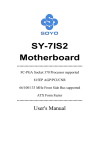
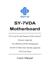
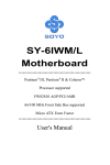
SY-K7AIA Motherboard **************************************************** AMD ™K7 Processor supported AMD 750 AGP/PCI Motherboard 100 MHz Front Side Bus supported ATX Form Factor **************************************************** User's Manual SOYO ™ SY-K7AIA Copyright © 1999 bySoyo Computer Inc. Trademarks: Soyo is the registered trademark of Soyo Computer Inc. All trademarks are the properties of their owners. Product Rights: All names of the product and corporate mentioned in this publication are used for identification purposes only. The registered trademarks and copyrights belong to their respective companies. Copyright Notice: All rights reserved. This manual has been copyrighted by Soyo Computer Inc. No part of this manual may be reproduced, transmitted, transcribed, translated into any other language, or stored in a retrieval system, in any form or by any means, such as by electronic, mechanical, magnetic, optical, chemical, manual or otherwise, without permission in writing from Soyo Computer Inc. Disclaimer: Soyo Computer Inc. makes no representations or warranties regarding the contents of this manual. We reserve the right to amend the manual or revise the specifications of the product described in it from time to time without obligation to notify any person of such revision or amend. The information contained in this manual is provided to our customers for general use. Customers should be aware that the personal computer field is subject to many patents. All of our customers should ensure that their use of our products does not infringe upon any patents. It is the policy of Soyo Computer Inc. to respect the valid patent rights of third parties and not to infringe upon or to cause others to infringe upon such rights. Restricted Rights Legend: Use, duplication, or disclosure by the Government is subject to restrictions set forth in subparagraph (c)(1)(ii) of the Rights in Technical Data and Computer Software clause at 252.277-7013. About This Guide: This Quick Start Guide can help system manufacturers and end users in setting up and installing the Motherboard. Information in this guide has been carefully checked for reliability; however, to the correctness of the contents there is no guarantee given. The information in this document is subject to amend without notice. For further information, please visit our Web Site on the Internet. The address is "http://www.soyo.com.tw". Tested To Comply With FCC Standards FOR HOME OR OFFICE USE C FC Edition: January 2000 Version 1.0 K7AIA SERIAL 100% ii POST CONSUMER RECYCLED PAPER Table of Contents SY-K7AIA Table of Contents CHAPTER 1 MOTHERBOARD DESCRIPTION .............................1 1-1 INTRODUCTION ...........................................................1 1-2 1-3 1-4 1-5 1-6 1-7 1-8 1-9 KEY FEATURES ............................................................1 HANDLING THE MOTHERBOARD .............................5 ELECTROSTATIC DISCHARGE PRECAUTIONS ........5 SY-K7AIA MOTHERBOARD LAYOUT........................6 SY-K7AIA MOTHERBOARD COMPONENTS .............7 MICROPROCESSOR......................................................9 MEMORY.....................................................................10 CHIPSET ......................................................................11 1-10 1-11 1-12 I/O INTERFACE CONTROLLER .................................15 HARDWARE MONITOR..............................................17 WAKE ON LAN TECHNOLOGY.................................17 CHAPTER 2 HARDWARE INSTALLATION..................................18 2-1 2-2 2-3 PREPARATIONS ..........................................................18 UNPACKING THE MOTHERBOARD .........................19 INSTALLATION GUIDE ..............................................20 2-3.1 CPU Fan Installation.................................................. 21 2-3.2 SDRAM Memory Module Installation.......................... 25 2-3.3 Motherboard Connector.............................................. 27 3-3.4 Power On ................................................................... 42 2-3.5 Quick BIOS Setup ....................................................... 43 2-3.6 Troubleshooting at First Start ..................................... 45 2-3.7 Power Off................................................................... 46 CHAPTER 3 BIOS SETUP UTILITY ..............................................47 3-1 3-2 3-3 SOYO COMBO SETUP.................................................50 STANDARD CMOS SETUP ..........................................53 ADVANCED BIOS FEATURES.....................................56 iii Table of Contents 3-4 3-5 3-6 3-7 3-8 3-9 3-10 3-11 3-12 3-13 SY-K7AIA ADVANCED CHIPSET FEATURES..............................60 INTEGRATED PERIPHERALS ....................................63 POWER MANAGEMENT SETUP................................67 PNP/PCI CONFIGURATION SETUP.............................70 PC HEALTH STATUS....................................................73 LOAD FAIL-SAFE DEFAULTS.....................................75 LOAD OPTIMIZED DEFAULTS...................................76 SUPERVISOR PASSWORD..........................................77 USER PASSWORD........................................................78 IDE HDD AUTO DETECTION .....................................79 CHAPTER 4 DRIVERS INSTALLATION ........................................79 iv Motherboard Description SY-K7AIA Chapter 1 MOTHERBOARD DESCRIPTION 1-1 INTRODUCTION The SY-K7AIA AGP/PCI Motherboard is a high-performance Slot A supported ATX form-factor system board. SY-K7AIA uses the AMD 750 Chipset technology and supports Slot A class processors. This Motherboard is fully compatible with industry standards and adds many technical enhancements. 1-2 KEY FEATURES Ø CPU SUPPORT The SY-K7AIA supports a wide range of AMD ™CPUs: n AMD ™(500~750+) MHz New released Intel Slot A CPUs will very likely be supported by the SYK7AIA as well. Ø CPU SETTINGS The SY-K7AIA provides the user with a very complete and convenient CPU setting environment. The CPU settings are auto detected and set automatically, therefore rendering the use of jumpers obsolete. n CPU FSB Frequency The SY-K7AIA supports a wide range of CPU FSB frequency settings: 500,550,600,650,700,750,750+ 1 Motherboard Description SY-K7AIA n CPU Multiplier The SY-K7AIA supports a wide range of multipliers: 5.0,5.5,6.0,6.5,7.0,7.5. n CPU Core Voltage The CPU Core voltage is set automatically according to CPU needs. This makes the use of voltage jumpers unnecessary. Ø EXPANDABILITY The SY-K7AIA provides all the standard expansion slots, and many more additional expansion features: u Expansion slots n n n u Enhanced IO n n n n n n n n Ø 1 x 32-bit bus mastering AGP slot 5 x 32-bit bus mastering PCI slots 2 x 16-bit ISA slots Floppy disk controller 2x EIDE controllers with support for up to 4 Ultra DMA 33/66 devices Standard/EPP/ECP parallel port 2x 16550 compatible serial ports IrDA compatible infrared port 4x USB (Universal Serial Bus) connectors PS/2 mouse connector PS/2 keyboard connector ADVANCED FUNCTIONS The SY-K7AIA supports advanced functions such as: n ATA 66 IDE Ports In addition to the original two ATA33 (Ultra DMA/33) IDE ports, the SY-K7AIA supports two ATA66 (Ultra DMA/66) IDE ports that is capable of transferring data up to 66 Mbytes/sec (IDE DMA Mode 4). Ø Wake-On-LAN Supports Wake-On-LAN (Some advanced network cards can wake the system up over the network, the WOL connector are provided by the SY-K7AIA to support this function). 2 Motherboard Description SY-K7AIA n Multiple boot The SY-K7AIA supports booting from devices such as CD-ROM. n Power on by modem or alarm If the SY-K7AIA system is in suspend mode, it can be switched back on through the modem or RTC alarm through this function. This opens a lot of possibilities, such as remote access that switches the system on only after the modem receives a call. Ø FAIL SAFE The SY-K7AIA comes with added functionality to make managing the system easy and safe. u Hardware Monitor The integrated Winbond Hardware Monitor IC and Hardware doctor software enables the user the monitor system voltages, temperatures and FAN speeds. This makes sure that the user is full control of the system Ø NORTON SOFTWARE PACK n n n Antivirus Ghost Virtual Drive 3 Motherboard Description Ø SY-K7AIA COMPLIANCE The SY-K7AIA complies with all important industry standards. The following underlines the reliability of the SY-K7AIA, a motherboard to trust. n Year 2000 compliant n PC99 compliant n FCC/CE complaint Ø USER FRIENDLY n n n SOYO Combo Setup Jumperless design You can set up the following options trough the BIOS setting CPU FSB frequency (auto detect) CPU multiplier (auto detect) PCI clock AGP Clock SDRAM Clock 4 Motherboard Description 1-3 SY-K7AIA HANDLING THE MOTHERBOARD To avoid damage to your Motherboard, follow these simple rules while unpacking: Ø Before handling the Motherboard, ground yourself by grasping an unpainted portion of the system's metal chassis. Ø Remove the Motherboard from its anti-static packaging. Hold the Ø Motherboard by the edges and avoid touching its components. Check the Motherboard for damage. If any chip appears loose, press carefully to seat it firmly in its socket. Warning: Do not apply power if the Motherboard appears damaged. If there is damage to the board, contact your dealer immediately. 1-4 ELECTROSTATIC DISCHARGE PRECAUTIONS Make sure to ground yourself before handling the Motherboard or other system components. Electrostatic discharge can easily damage the components. Note that you must take special precautions when handling the Motherboard in dry or air-conditioned environment. To protect your equipment from electrostatic discharge, take the following precautions: Ø Do not remove the anti-static packaging until you are ready to install. Ø Ground yourself before removing any system component from its protective anti-static packaging. (To ground yourself, grasp the expansion slot covers or other unpainted portions of the computer chassis.) Ø Frequently ground yourself while working or use a grounding strap. Ø Handle the Motherboard by its edges and avoid touching its components. 5 Motherboard Description SY-K7AIA 1-5 SY-K7AIA MOTHERBOARD LAYOUT PS/2 KB Connector USB 1 PS/2 Mouse Connector USB 2 DIMM 3 DIMM 2 DIMM 1 Slot A ® FDC PRT COM 1 Winbond W83782D PWR1 828AC Hardware Monitoring AMD® COM 2 11 751AC CPUFAN 1 J17 J4 PCI Slot #2 PCI Slot #3 PCI Slot #4 756AC _ W83977ATF Reset HDD SLPBT LED _ PWRBT + AMD Winbond Speaker Flash PCI Slot #5 ISA Slot #1 ISA Slot #2 Back Panel SY-K7AIA Platform 6 Power Keylock LED CHAFAN ROM 2MB 1 5 1 ® + WOL Header + 1 5 _ 3 J3 PCI Slot #1 J16 1 1 IDE 1 IDE 2 _ 4 AGP Slot + 1 3V Lithium Battery 1 Motherboard Description SY-K7AIA 1-6 SY-K7AIA MOTHERBOARD COMPONENTS A B C D E F G ® V ® 1 H I J U T K L M N ® S R O Q P 7 Motherboard Description SY-K7AIA A Slot A Connector B CPU Cooling Fan Connector C AMD 751AC Chipset D ATX Power Supply Connector E DIMM Banks F Winboand W83782M hardware monitoring G Floppy Disk Drive (FDD) Port H Bus Mastering E-IDE/ATAPI Ports I 32-bit AGP Slot J Serial Infrared (IrDA) Device Header K USB Ports L AMD 756AC Chipset M Front panel connectors N 32-bit PCI Mastering Slots O Chassis Cooling Fan Connector P 3V Lithium Battery Q 16-bit ISA Slots R Flash ROM 2MB S Winbond W83977ATF I/O Chipset T Wake-On-LAN (WOL) Header U Wake-On-Modem Header V Back panel Connectors 8 Motherboard Description SY-K7AIA 1-7 MICROPROCESSOR The motherboard supports a single Slot A processor. The processor’s VID pins automatically program the voltage regulator on the motherboard to the required processor voltage. In addition, the front side bus speed (66 MHz and 100 MHz) is automatically selected. The motherboard supports all (available at time of publication) Slot A processor speeds, voltages, and bus frequencies. 1-7.1 Microprocessor Packaging The processor is packaged in a Single Edge Contact Cartridge (SECC or SECC2) or Single Edge Processor Package (S.E.P.P). The cartridge includes the processor core, second-level cache subsystem, thermal plate, and back cover. The processor connects to the motherboard through the SlotA connector, a 242-pin edge connector. When mounted in SlotA, the processor is secured by a retention mechanism attached to the motherboard. A passive heatsink is stabilized by the heatsink supports. 1-7.2 Second Level Cache The second-level cache is located on the substrate of the CPU package. The cache includes 512 KB of synchronous pipelined burst static RAM. All supported onboard memory can be cached. 1-7.3 Microprocessor Upgrades The motherboard can be upgraded with Slot A processors that run at higher speeds. 9 Motherboard Description SY-K7AIA 1-8 MEMORY 1-8.1 Main Memory The motherboard has four DIMM sockets. SDRAM can be installed in one, two, three, or four sockets. Using the serial presence detect (SPD) data structure, programmed into an E²PROM on the DIMM, the BIOS can determine the SDRAM’s size and speed. Minimum DIMM memory size is 8 MB; maximum DIMM memory size is 256MB. Memory size and speed can vary between sockets. The motherboard supports the following memory features: l 168-pin DIMMs with gold-plated contacts l 66/100/133 MHz SDRAM l Non-ECC (64-bit) and ECC (72-bit) memory l 3.3V memory only l Supports 8/16/32/64/128/256 MB DIMM Modules l Supports unbuffered single- or double-sided DIMMs 1-8.2 SDRAM SDRAM improves memory performance through memory access that is synchronous with the front-side bus clock. Burst transfer rates at x-1-1-1 timing can be achieved using SDRAM, while asynchronous memory subsystem are typically limited at x-2-2-2 transfer rates. Note All memory components and DIMMs used with the SY-K7AIA motherboard must comply with the PC SDRAM specifications. These include: the PC SDRAM Specification (memory component specific), the PC Unbuffered DIMM Specification, and the PC Serial Presence Detect Specification. 1-8.3 ECC Memory ECC memory detects multiple-bit errors and corrects single-bit errors. When ECC memory is installed, the BIOS supports both ECC and nonECC mode. ECC mode is enabled in the Setup program. The BIOS 10 Motherboard Description SY-K7AIA automatically detects if ECC memory is installed and provides the Setup option for selecting ECC mode. If any non-ECC memory is installed, the Setup option for ECC configuration does not appear and ECC operation is not available. 1-9 CHIPSET The AMD-K7 ™processor powers the next generation in computing platforms, delivering the ultimate performance for cutting-edge applications and an unprecedented computing experience. The AMD-750 ™Chipset is a highly integrated system logic solution that delivers maximum performance for the AMD-K7 processor and other S2K interface-compatible processors. The AMD-750 chipset consists of the uniprocessor AMD-751 ™system controller in a 492-pin plastic ball-grid array (PBGA) package and the AMD-756 ™peripheral bus controller. The AMD-751 system controller features the S2K interface, system memory controller, accelerated graphics port (AGP) controller, and peripheral component interconnect (PCI) bus controller. The AMD-751 system controller is designed with the following features: l The S2K interface supports a 100-MHz clock and double-data-rate (DDR) transfers l The 33-MHz 32-bit PCI 2.2-compliant bus interface supports up to six masters l The 66-MHz AGP 2.0-compliant interface supports 2x data transfer l mode High-speed memory – The AMD-751 system controller is designed to support a 100-MHz PC-100 SDRAM DIMMs 1-9.1 S2K interface The S2K interface has the following fetures: l High-performance point-to-point bus l HSTL-like 1.5 V high-speed transceiver logic signal levels l Independent address, data, and snoop interfaces l l Double-data-rate transfers on address and data buses Data Buffers: 11 Motherboard Description l SY-K7AIA Memory write FIFO (MWF) Memory read FIFO (MRF) PCI/APCI (AGP-PJCI) write buffer PCI/APCI read buffer Transaction Queues: Command queue (CQ) Memory write queue (MWQ) Memory read queue (MRQ) Probe (snoop) queue (PQ) 1-9.2 Integrated memory controller The integrated memory controller has the following features: l Memory Request Organizer (MRO) – Serves as a data crossbar, determines request dependencies, and optimizes scheduling of l memory requests. The AMD-751 system controller supports the following concurrences: l Processor-to-main-memory with PCI-to-Main-memory Processor-to-main-memory with AGP-to-Main-memory Processor-to-=PCI with PCI-to-Main-memory or AGP-to-mainmemory Memory error correcting code (ECC) support l Supports the following DRAM: l l l l Up to three non-buffered PC-100 SDRAM DIMMs using 16Mbit, 64Mbit-, and 128Mbit technology 64-bit data width, plus 8-bit ECC paths Flexible row and column addressing Supports up to 768 Mbytes of memory Four open pages within one CS (device selected by chip select) for one quadword Default two-page leapfrog policy for eight quadword requests BIOS-configurable memory-timing parameters and configuration 12 Motherboard Description SY-K7AIA l l parameters 3.3-V memory interface operation with no external buffers Four cache lines (32 quadwords) of processor-to-DRAM posted write buffers with full read-around capability Concurrent DRAM write back and read-around-write Burst read and write transactions l l Decoupled and burst DRAM refresh with staggered CS timing Provides the following refresh options: l l Programmable refresh rate CAS-before-RAS Populated banks only Chipset powerdown via SDRAM automatic refresh command Automatic refresh of idle slots – improves bus availability for memory access by the processor or system 1-9.3 PCI Bus Controller The PCI bus controller has the following features: l Compliance with PCI Local Bus Specification, Revision 2.2 l Supports six PCI masters l 32-bit interface, compatible with 3.3-V and 5-V PCI I/O l Synchronous PCI bus operation up to 33 MHz l PCI-initiator peer concurrence l Automatic processor-to-PCI burst cycle detection l l l l l l Four-entry, 64-bit PCI master (processor or AGP) write FIFO Extensive utilization of FIFOs Zero wait-state PCI initiator and target burst transfers PCI-to-DRAM data streaming up to 132 Mbytes per second Enhanced PCI command optimization, such as memory read line (MRL), memory read multiple (MRM), and memory-write-andinvalidate (MWI) Timer-enforced fair arbitration between PCI initiators l l Supports advanced concurrency Supports retry disconnect for improved bus utilization 13 Motherboard Description l l SY-K7AIA PCI read buffer keeps track of each master PCI target request queue 1-9.4 AGP Features The AGP features include the following: l Bus Features l Compliance with AGP 2.0 specification Synchronous 66-MHz 1x and 2x data-transfer modes Multiplexed and demultiplexed transfers Up to four pipelined grants Support of side band address (BA) bus Request Queue Features Separate read-request and write-request queues Reordering of high-priority requests over low-priority requests in queue Simultaneous issuing of requests form both the write queue and read 2queue l Selects next request to optimize bus utilization Transaction Queues l Memory-to-AGP and processor-to-AGP transaction queues FIFO Features l 16-entry (64-bit) AGP-to-memory write FIFO 64-entry (64-bit) memory-to9-AGP read FIFO Secondary PCI Bus Features l Pipelined burst reads and writes Extensive utilization of FIFOs GART (graphics address remapping table) Features Conventional (two-level) GART scheme Eight-entry, fully-associative GART table cache (GTC) Three fully-associative GART directory caches (GDC) u One 4-entry for PCI u u One 8-entry for the processor One 16-entry for AGP 14 Motherboard Description SY-K7AIA 1-9.5 Power management The power management features include the following: l Full-compliance support for both ACPI and Microsoft ® PC 98 power management l AMD-751 system controller supports the following three power states: l Full-on – Fully operational Halt/Stop Grant – The AMD-7851 disconnects the processor and, in the Stop Grant state, the SDRAMs are put into selfrefresh. 1-10 I/O INTERFACE CONTROLLER The motherboard uses the Winbond W83977ATF I/O controller which features: l Single diskette drive interface l l l Two serial ports FIFO supports on both serial and diskette interfaces One parallel port with Extended Capabilities Port (ECP) and Enhanced Parallel Port (EPP) support l PS/2 style mouse and keyboard interfaces l PCI PME interface l Intelligent auto power management, including: Ø Shadowed write-only registers for ACPI compliance Ø Programmable wake-up event interface The Setup program provides configuration option for the I/O controller. 1-10.1 Serial Ports The NS16C5450-compatible UARTs support data transfers at speeds up to 115.2 Kbits/sec with BIOS support. 1-10.2 Parallel Port In the Setup program, there are four options for parallel port operation: l Compatible (standard mode) l Bi-directional (PS/2 compatible) 15 Motherboard Description l l SY-K7AIA Bi-directional EPP. A driver from the peripheral manufacturer is required for operation. Bi-directional high-speed ECP 1-10.3 Diskette Drive Controller The I/O controller is software compatible with the 82077 diskette drive controller and supports both PC-AT and PS/2 modes. In the Setup program, the diskette drive interface can be configured for the following diskette drive capacities and sizes. l 360 KB, 5.25-inch l 1.2 MB, 5.25-inch l 720 KB, 3.5-inch l 1.2 MB. 3.5-inch (driver required) l 1.25-1.44 MB, 3.5-inch l 2.88 MB, 3.5-inch 1-10.4 Keyboard and Mouse Interface The +5 V lines to keyboard and mouse connectors are protected with a fuse that prevents motherboard components from being damaged when an over-current condition occurs. The keyboard controller contains code, which provides the traditional keyboard and mouse control functions, and also supports Power On/Reset password protection. Power On/Reset password can be specified in the BIOS Setup program. The keyboard controller also supports the hot-key sequence <Ctrl><Alt><Del>, software reset. This key sequence resets the computer’s software by jumping to the beginning of the BIOS code and running the Power On Self Test (POST). 1-10.5 Infrared Support The IR connection can be used to transfer files to or from portable devices like laptops, PDAs, and printers. 16 Motherboard Description SY-K7AIA 1-11 HARDWARE MONITOR The optional hardware monitor subsystem provides low-cost instrumentation capabilities. The features of the hardware monitor subsystem include: Ø An integrated ambient temperature sensor Ø Fan speed sensors, which monitor the fan 1 and fan 2 connectors Ø Power supply voltage monitoring to detect levels above or below acceptable values When suggested ratings for temperature, fan speed, or voltage are exceeded, an interrupt is activated. The hardware monitor component connects to the SMBus. 1-12 WAKE ON LAN TECHNOLOGY Wake on LAN technology enables remote wakeup of the computer through a network. Wake on LAN technology requires a PCI add-in network interface card (NIC) with remote wakeup capabilities. The remote wakeup connector on the NIC must be connected to the onboard Wake on LAN technology connector. The NIC monitors network traffic at the MII interface; upon detecting a Magic Packet, the NIC asserts a wakeup signal that powers up the computer. To access this feature uses the Wake on LAN technology connector. * CAUTION For Wake on LAN, the 5-V standby line for the power supply must be capable of delivering +5V ±5 % at 720 mA. Failure to provide adequate standby current when implementing Wake on LAN can damage the power supply. 17 Hardware Installation SY-K7AIA Chapter 2 HARDWARE INSTALLATION Congratulations on your purchase of SY-K7AIA Motherboard. You are about to install and connect your new Motherboard. Note: Do not unpack the Motherboard from its protective antistatic packaging until you have made the following preparations. 2-1 PREPARATIONS Gather and prepare all the following hardware equipment to complete the installation successfully: 1. Slot A processor with built-in CPU cooling fan (boxed type). Note: This Motherboard supports non-boxed type CPUs. The heavier CPU cooling fan requires the installation of a CPU support stand. 2. DIMM memory module 3. Computer case and chassis with adequate power supply unit 4. Monitor 5. PS/2 Keyboard 6. Pointing Device (PS/2 mouse) 7. Speaker(s) (optional) 8. Disk Drives: HDD, CD-ROM, Floppy drive … 9. External Peripherals: Printer, Plotter, and Modem (optional) 10. Internal Peripherals: Modem and LAN cards (optional) 18 Hardware Installation 2-2 SY-K7AIA UNPACKING THE MOTHERBOARD When unpacking the Motherboard, check for the following items: u The SY-K7AIA AMD 750 AGP/PCI Motherboard u The Quick Start Guide u The Installation CD-ROM u SOYO 3-in-1 Bonus Pack CD-ROM (Norton AntiVirus, Ghost and Virtual Drive) u The CPU Retention Set u One IDE Device ATA 66 Flat Cable u One Floppy Disk Drive Flat Cable Warning: Do not unpack the Motherboard from its anti-static packaging until you are ready to install it. Like most electronic equipment, your Motherboard may be damaged by electrostatic discharge. To avoid permanent damage to components ground yourself while working by using a grounding strap. Otherwise, ground yourself frequently by touching the unpainted portion of the computer chassis to drain the static charges. Handle the Motherboard carefully, holding it by the edges. You are now ready to start the installation. 19 Hardware Installation SY-K7AIA 2-3 INSTALLATION GUIDE We will now begin the installation of the Motherboard. Please follow the step-by-step procedure designed to lead you to a complete and correct installation. Warning: Turn off the power to the Motherboard, system chassis, and peripheral devices before performing any work on the Motherboard or system. BEGIN THE INSTALLATION 20 Hardware Installation SY-K7AIA 2-3.1 CPU Installation Your SY-K7AIA motherboard comes with a CPU retention set kit. The retention set is used to hold the processor attached to the Slot A CPU connector on the motherboard. Mark your CPU Frequency: Record the working frequency of your CPU that should be clearly marked on the CPU cover. FSB 100MHz 500MHz (100 x 5.0) 550 MHz (100 x 5.5) 600 MHz (100 x 6.0) 650MHz (100 x 5.0) 700 MHz (100 x 5.5) 750 MHz (100 x 6.0) Follow these instructions to install your Slot A processor correctly. Ø Retention Module 21 Hardware Installation SY-K7AIA 1. Open the two sides by folding them up. 2. Push the locks on top of the CPU inward. 22 Hardware Installation SY-K7AIA 3. Insert the CPU into the retention module. The CPU fits in the CPU slot in only ONE way, do not try to force it in. 4. After completely inserting the CPU, push the two locks on top of the CPU outward. Now your CPU is ready for use. To remove the CPU, press the two notches on top of the CPU inward. Now press the two slides on the retention module down and remove the CPU. 23 Hardware Installation SY-K7AIA Note: Installing a heat sink and cooling fan on top of your CPU is necessary for proper heat dissipation. Failing to install these items may result in overheating and possible burn-out of your CPU. 2-3.1.1 CPU Fan Installation Your Slot A processor kit comes with a cooling fan. Mount the fan on the processor according to the instructions provided by the manufacturer. The fan is a key component that will ensure system stability. The fan prevents overheating, therefore prolonging the life of your CPU. Note: Remember to connect the fan to the appropriate power source. 24 Hardware Installation SY-K7AIA 2-3.2 SDRAM Memory Module Installation ® ® 1 ® DIMM 3 DIMM 2 DIMM 1 Your board comes with three DIMM sockets, providing support for up to 768MB of main memory using unbuffered DIMM modules from 8MB to 256MB. PC100 DIMM module is required on this motherboard. 84 1 1 84 25 Hardware Installation SY-K7AIA Memory Configuration Table Memory Configuration RAM Type DIMM Banks DIMM 1 DIMM 2 DIMM 3 SDRAM SDRAM SDRAM RAM Module 8/16/32/64/128/256 8/16/32/64/128/256 8/16/32/64/128/256 Size (MB) Note: No support for registered memory modules. 26 Hardware Installation SY-K7AIA 2-3.3 Motherboard Connector ® ® 1 ® IDE 2 IDE 1 Pin -1 Secondary Primary IDE IDE 2-3.3.1 IDE Device Installation (HDD, CD-ROM) This Motherboard offers two primary and secondary IDE device connectors (IDE1, IDE2.) It can support up to four high-speed HDDs or CD-ROMs. Connect one side of the 40-pin (ATA-33 or below) / 80-pin (ATA-66) flat cable to the IDE device (HDD or CD-ROM) and plug the other end to the primary (IDE1) or secondary (IDE2) directionally keyed IDE connector on the Motherboard. This Motherboard can support up to four ATA 33/66 IDE devices. 80-Conductor ATA 66 Flat Cable 1 40-pin 39 1 39 27 Hardware Installation SY-K7AIA 2-3.3.2 Floppy Drive Installation ® 1 ® Pin -1 FDC Floppy Drive Connector ® The system supports 5 possible floppy drive types: 720 KB, 1.2 MB, 1.44 MB, 2.88 MB, and LS-120. Connect one side of the 34-pin flat cable to the floppy drive and plug the other end to the floppy drive connector on the Motherboard. This Motherboard can support up to 2 floppy drives. 1 33 1 33 28 Hardware Installation SY-K7AIA 2-3.3.3 Front Panel Connections ® _ _ _ Speaker + + + + Reset HDD SLPBT PWRBT LED _ 1 ® Power Keylock LED ® Plug the computer case's front panel devices to the corresponding headers on the Motherboard. 1. Power LED & KeyLock Plug the Power LED cable into the 5-pin Keylock header. Some systems may feature a KeyLock function with a front panel switch for enabling or disabling the keyboard. Connect the KeyLock switch to the 5-pin Keylock header on the Motherboard. Please install according to the following pin assignment: pin 1,3 are for Power LED and pin 4,5 are for Keylock. Power LED Pin Assignment _ + +5V Key Lock Pin Assignment NC 1 GND Control Pin 29 GND Hardware Installation SY-K7AIA 2. Reset Plug the Reset push-button cable into the 2-pin Reset header on the Motherboard. Pushing the Reset button on the front panel will cause the system to restart the boot-up sequence. Reset Pin Assignment 1 Power Good GND 3. Speaker Attach the 4-pin PC speaker cable from the case to the Speaker header on the Motherboard. Speaker Pin Assignment _ + +5V 4. Speaker out NC NC Sleep Button Sleep Button Pin Assignment + _ LED Cathode GND 30 Hardware Installation SY-K7AIA 5. IDE LED Attach the 2-pin IDE device LED cable to the corresponding IDE LED header on the Motherboard. This will cause the LED to lighten when an IDE (HDD, CD-ROM) device is active. HDD LED Pin Assignment + _ LED Anode LED Cathode 6. ATX Power On/Off Switch Attach the 2-pin momentary type switch to the PWRBT header for turning On or Off your ATX power supply. PWRBT Pin Assignment 1 Power On/Off 31 GND Hardware Installation SY-K7AIA 2-3.3.4 Back Panel Connections All external devices such as the PS/2 keyboard, PS/2 mouse, printer, modem, USB can be plugged directly onto the Motherboard back panel. Only after you have fixed and locked the Motherboard to the computer case can you start connecting the external peripheral devices. When connecting an external device, use the following figure to locate and identify which back panel connector to plug the device to. PS/2 KB PS/2 Mouse Connector Connector ® ® USB 1 1 USB 2 PRT COM 1 ® COM 2 32 Hardware Installation SY-K7AIA 1. Onboard Serial Ports COM1/COM2 External peripherals that use serial transmission scheme include: - serial mouse, - and modem. Plug the serial device cables directly into the COM1/COM2 9-pin male connectors located at the rear panel of the Motherboard. 2. Parallel Port PRT This parallel port is used to connect the printer or other parallel devices. Plug the parallel device cable into the 25-pin female connector located at the rear panel of the Motherboard. 3. PS/2 Keyboard Plug the keyboard jack directly into the 6-pin female PS/2 keyboard connector located at the rear panel of the Motherboard. Pin6 NC Pin4 VCC Pin2 NC Pin5 KBD Clock Pin3 GND Pin1 KBD DATA 4. PS/2 Mouse Similarly, plug the mouse jack directly into the 6-pin female PS/2 mouse connector. Pin6 NC Pin5 Mouse Clock Pin4 VCC Pin2 NC Pin3 GND Pin1 Mouse DATA 33 Hardware Installation SY-K7AIA 5. Universal Serial Bus USB1/USB2/J4(USB3, USB4) This Motherboard provides four USB ports for your additional devices. Plug the USB device jack into the available USB connector USB1 or USB2. Standard device drivers come with the Win98 for commonly used USB devices. With Win95, use the flow UHCI specifications. To use USB devices under Win95, usually you have to install the device that driver comes with the USB device you have purchased. USB3 and 4 are available through JP4. To make use of these USB ports, purchase a USB cable from your dealer. The lay-out of JP4 is as follow: - J4 (USB4) (USB3) 5 10 GND GND GND GND 4 9 (+)Data (+)Data 3 8 (-)Data 7 2 (-)Data Power 6 1 Power 34 Hardware Installation SY-K7AIA 2-3.3.5 Other Connections 1. Wake-On-LAN (WOL) Attach the 3-pin connector from the LAN card which supports the WakeOn-LAN (WOL) function to the J17 header on the Motherboard. This WOL function lets users wake up the connected computer through the LAN card. Please install according to the following pin assignment: Wake-On-LAN JP17 Pin Assignment 3 2 MP-Wake-up GND 35 1 5VSB Hardware Installation SY-K7AIA 2. Wake-On-Modem (J16) Attach the 4-pin connector from the modem card which supports the Wake-On-Modem function to the J16 header on the Motherboard. This Wake-On-Modem function lets users wake up the connected computer through the Modem card. Please install according to the following pin assignment: Wake-On-Modem J16 Pin Assignment 1 2 3 4 GND None MP_Wakeup 36 5VSB Hardware Installation SY-K7AIA 3. Infrared (J3) Plug the 5-pin infrared device cable to the J3 header. This will enable the infrared transfer function. This Motherboard meets both the ASKIR and HPSIR specifications. Please install according to the following pin assignment: Serial Infrared (J3) Connector J3 Pin Assignment 1 2 3 4 5 VCC IRRX GND 37 IRTX Hardware Installation 4. SY-K7AIA Cooling Fan Installation (1) CPU Cooling Fan After you have seated the CPU properly on the processor, attach the 3-pin fan cable to the CPUFAN connector on the Motherboard. The fan will stop when the system enters into Suspend Mode. (Suspend mode can be enabled from the BIOS Setup Utility, [POWER MANAGEMENT] menu.) To avoid damage to the system, install according to the following pin assignment: CPU Cooling Fan CPUFAN Pin Assignment 3 SENSOR 2 12V 38 1 GND Hardware Installation SY-K7AIA (2) Chassis Cooling Fan Some chassis also feature a cooling fan. This Motherboard features a CHAFAN connector to provide 12V power to the chassis fan. Connect the cable from the chassis fan to the CHAFAN 3-pin connector. Install according to the following pin assignment: Chassis Cooling Fan CHAFAN Pin Assignment 3 SENSOR 2 12V 1 GND Note: CPUFAN must be installed for this Motherboard, CHAFAN is optional. 39 Hardware Installation SY-K7AIA 2-3.3.6 AGP VGA Card Insert the AGP VGA card into the AGP slot. Then connect the monitor information cable to the AGP card back plane external connector. Follow the manufacturer's instructions to perform the AGP VGA drivers installation. Other Display Cards: Insert other types of VGA cards into the PCI or ISA expansion slots according to card specifications. 40 Hardware Installation SY-K7AIA 2-3.3.7 ATX Power Supply Plug the connector from the power directly into the 20-pin male ATX PW connector on the Motherboard, as shown in the following figure. ATX Power ® ® 1 ® Warning: Follow these precautions to preserve your Motherboard from any remnant currents when connecting to power supply: Turn off the power supply and unplug the power cord of the power supply before connecting to PW connector. 41 Hardware Installation SY-K7AIA This motherboard requires a power supply, that meets the ATX 2.03 specifications. Make sure the power supply can support at least 720mA on the 5V Standby lead. Please install the ATX power according to the following pin assignment: ATX Power 12V 5VSB PW-OK GND 5V 5V -5V GND GND 5V GND 5V Ø Pay special care to the directionality. GND PS-ON GND GND 3.3V -12V 3.3V 3.3V 2-3.4 Power On You have now completed the hardware installation of your Motherboard successfully. 1. Turn the power on 2. To enter the BIOS Setup Utility, press the <DEL> key while the system is performing the diagnostic checks, Note: If you have failed to enter the BIOS, wait until the boot up sequence is completed. Then push the RESET button and press <DEL> key again at the beginning of boot-up, during diagnostic checks. 42 Hardware Installation SY-K7AIA Repeat this operation until you get the following screen. 3. The BIOS Setup screen appears: CMOS Setup Utility – Copyright ( C ) 1984-1999 Award Software 4Soyo Combo Feature 4PC Health Status 4Standard CMOS Features Load Optimized Defaults 4Advanced BIOS Features Load Fail - Safe Defaults 4Advanced Chipset Features Set Supervisor Password 4Integrated Peripherals Set User Password 4Power Management Setup Save & Exit Setup 4PnP/PCI Configurations Exit Without Saving áâàß Esc : Quit F10 : Save & Exit Setup : Select Item Change CPU’s Clock & Voltage 2-3.5 Quick BIOS Setup This Motherboard does not use any hardware jumpers to set the CPU frequency. Instead, CPU settings are auto detected and set automatically. The [SOYO COMBO SETUP] menu combines the main parameters that you need to configure, all in one menu, for a quick setup in BIOS. After the hardware installation is complete, turn the power switch on, then press the <DEL> key during the system diagnostic checks to enter the Award BIOS Setup program. The CMOS SETUP UTILITY will display on screen. Follow these steps to configure the CPU settings. SETUP UTILITY will display on screen. Then, follow these steps to configure the CPU settings. 43 Hardware Installation SY-K7AIA Step 1. Select [STANDARD CMOS SETUP] Set [Date/Time] and [Floppy drive type], then set [Hard Disk Type] to “Auto”. Step 2. Select [LOAD SETUP DEFAULT] Select the “LOAD SETUP DEFAULT” menu and type “Y” at the prompt to load the BIOS optimal setup. Step 3. Select [SOYO COMBO SETUP] Move the cursor to the [CPU Frequency] field to see the CPU frequency. Available [CPU Frequency] settings on your SY-K7AIA Motherboard are detailed in the following table. CPU Frequency (MHz) 500MHz (100 x 5.0) 550MHz (100 x 5.5) 600MHz (100 x 6.0) 650MHz (100 x 6.5) 700MHz (100 x 7.0) 750MHz (100 x 7.0) Note: This is auto detect function. You can see your CPU clock and Ratio, but that is not adjustable. Step 4. Select [SAVE & EXIT SETUP] Press <Enter> to save the new configuration to the CMOS memory, and continue the boot sequence. 44 Hardware Installation SY-K7AIA 2-3.6 Troubleshooting at First Start l 1. 2. 3. 4. 5. 6. What should I do if the Motherboard refuses to start? Check that all DIMM memory modules are inserted completely. Sometimes a DIMM that is not inserted properly can cause boot problems. Check whether all Add-on cards have been inserted properly. Reinsert the Add-on cards to make sure that they make proper contact with the slots. Try removing all Add-on cards one by one to see whether or not one of them is causing problems. (Switch the system off before removing any of the cards. Verify that speed settings are not exceeding specifications. This applies to the PCI bus, that is specified to run at 33 MHz. Also check the speed setting for the memory, make sure conservative setting is used. If the CPU is overclocked the system may not start up, read the section below. Make sure that the Harddisk IDE cables are attached properly, if not the system will not boot. In case of doubt try reversing the IDE connector on one end of the cable. Verify that the 110/220V switch on the back of the power supply is set correctly. Go through the jumper setting section again to make sure that all jumpers are set correctly. 45 Hardware Installation SY-K7AIA 2-3.7 Power Off There are two possible ways to turn off the system: 1. Use the Shutdown command in the Start Menu of Windows 95/98 to turn off your computer. 2. Press the mechanical power-button and hold down for over 4 seconds, to shutdown the computer. If you press the power-button for less than 4 seconds, then your system will enter into Suspend Mode. You are now ready to configure your system with the BIOS setup program. Go to Chapter 3: BIOS SETUP 46 BIOS Setup Utility SY-K7AIA Chapter 3 BIOS SETUP UTILITY This Motherboard's BIOS setup program uses the ROM PCI/ISA BIOS program from Award Software Inc. To enter the Award BIOS program's Main Menu: 1. Turn on or reboot the system. 2. After the diagnostic checks, press the [Del] key to enter the Award BIOS Setup Utility. CMOS Setup Utility – Copyright ( C ) 1984-1999 Award Software 4Soyo Combo Feature 4PC Health Status 4Standard CMOS Features Load Fail - Safe Defaults 4Advanced BIOS Features Load Optimized Defaults 4Advanced Chipset Features Set Supervisor Password 4Integrated Peripherals Set User Password 4Power Management Setup Save & Exit Setup 4PnP/PCI Configurations Exit Without Saving áâàß Esc : Quit F10 : Save & Exit Setup : Select Item Change CPU’s Clock & Voltage Selecting items l Use the arrow keys to move between items and select fields. l From the Main Menu press arrow keys to enter the selected submenu. Modifying selected items l Use the [Up]/[Down] keys to modify values within the selected fields. Some fields let you enter values directly. 47 BIOS Setup Utility SY-K7AIA Hot Keys: Function keys give you access to a group of commands throughout the BIOS utility. Function Command Description Gives the list of options available for each F1 General Help item. Previous Restore the old values. These are the values F5 Values that the user started the current session with. Load FailLoads all items with the most conservative F6 Safe Defaults values. Load F7 Optimized Loads all options with the optimize values. Defaults F10 Save Saves your changes and reboots the system. Returns at anytime and from any location to [Esc] Exit the Main Menu. Will display a overlapping window with all [Enter] Select options for the current item. Using the +, –, Page Up and Page Down [+/–/PU/PD] Value keys the user can toggle the value of the current item. 48 BIOS Setup Utility SY-K7AIA SAVE AND EXIT SETUP Select the [SAVE & EXIT SETUP] option from the Main Menu to save data to CMOS and exit the setup utility. This option saves all your changes and causes the system to reboot. R O M C M O S A W S T A N D A R D B IO S C M O S F E A T U R E S C H IP S E T P O W E R A R D P C I/IS A U T IL I T Y S O F T W A R E , IN C . IN T E G R A T E D P E R IP H E R A L S S U P E R V IS O R S E T U P F E A T U R E S B IO S S E T U P S E T U P U S E R S E T U P P A S S W O R D P A S S W O R D SAVE to CMOS and EXIT M A N A G E M E N T ID E S E T U P H D D P N P /P C I C O N F IG U R A T I O N S A V E L O A D S E T U P E X IT L O A D B IO S D E F A U L T S ↑ E s c : Q u it F 1 0 : S a v e & A U T O E X I T D E T E C T IO N S E T U P W I T H O U T S A V IN G D E F A U L T S & E x it S e t u p ↓ → ( S h i f t ) T im e , D a t e , H a r d D i s k ← : S e le c t F 2 : C h a n g e I t e m C o lo r T y p e … Type [Y] to save the changes and exit or [N] to return to the Main Menu and keep current values. EXIT WITHOUT SAVING Selecting the [EXIT WITHOUT SAVING] option allows you to abandon all data and exit setup, therefore ignoring all your changes. R O M C M O S A W A R D S T A N D A R D B IO S C M O S F E A T U R E S C H IP S E T P O W E R S E T U P S E T U P F E A T U R E S B IO S U T I L I T Y IN C . IN T E G R A T E D P E R IP H E R A L S S U P E R V IS O R S E T U P M A N A G E M E N T P C I/IS A S E T U P S O F T W A R E , S E T U P U S E R ID E P A S S W O R D P A S S W O R D H D D A U T O D E T E C T IO N Quit Without Saving (Y/N)? _ P N P / P C I C O N F IG U R A T IO N S A V E L O A D S E T U P E X IT L O A D B I O S D E F A U L T S & E X I T S E T U P W IT H O U T S A V IN G D E F A U L T S E s c : Q u it F 1 0 : S a v e & E x it S e t u p ↑ ↓ → ← (Shift) F2 : S e l e c t I t e m : C h a n g e C o l o r Tim e , D a t e , H a r d D i s k T y p e … 49 Type [Y] to abandon changes and exit or [N] to return to the Main Menu and keep current values. BIOS Setup Utility SY-K7AIA 3-1 SOYO COMBO SETUP This Motherboard does not use any hardware jumpers to set the CPU frequency. Instead, CPU settings are software configurable with the BIOS [SOYO COMBO SETUP]. After the hardware installation is complete, turn the power switch on, then press the <DEL> key during the system diagnostic checks to enter the Award BIOS Setup program. The CMOS SETUP UTILITY will display on screen. Then, select the [SOYO COMBO SETUP] option from the main menu and press the <Enter> key. CMOS Setup Utility – Copyright ( C ) 1984-1999 Award Software Soyo Combo Feature Main Processor System Clock CPU Host/PCI Clock External Cache Quick Power On Self Test AMD Athlon ™ 100 X 6.0 MHz Default Enabled Enabled First Boot Device Second Boot Device Third Boot Device Boot Other Device Floppy HDD-0 LS/ZIP Enabled Soft-Off by PWR-BTTN Wake-Up by PCI card RI Resume/WOL MODEM Use IRQ RTC Resume x Date (of Month) Alarm x Time (hh:mm:ss) Alarm áâàß:Move Enter:Select F5:Previous Values Item Help Menu Level 4 Instant-Off Disabled Disabled 3 Disabled 0 0 0 0 +/-/PU/PD:Value F10:Save F6:Fail-Safe Defaults ESC:Exit F1:General Help F7: Optimized Defaults The [SOYO COMBO SETUP] menu combines the main parameters that you need to configure, all in one menu, for a quick setup in BIOS. 50 BIOS Setup Utility SY-K7AIA 3-1.1 Quick CPU Frequency Setup Quick CPU Setting Frequency Setup Description Note Main Processor This item lists the CPU type, it is a read only item. System Clock The CPU settings are autodetected: list CPU multiplier here: [5.0, 5.5,6.0,6.5,7.0,7.5]. The CPU frequency is then defined as [host clock freq.]x[multiplier], and should the working frequency of your AMD Athlon processor. CPU Host/PCI clock Default 133/33 MHz 100/33 MHz This item lists the CPU Default host clock and the PCI bus clock. It is a read only item. 3-1.2 Cache Memory Options Setting External Cache Description Disabled Enabled Enables the external memory. Note Default 3-1.3 Quick Power On Self Test Setting Quick Power On Self Test Description Disabled Enabled Provides a fast POTS at boot-up. 51 Note Default BIOS Setup Utility SY-K7AIA 3-1.4 System Boot Control Settings System Boot Setting Control Settings Description First /Second/Third Boot Device Floppy LS/ZIP HDD-0 SCSI CDROM HDD-1 HDD-2 HDD-3 LAN Disabled Select Your Boot Device Priority Boot Other Device Disabled Enabled Select Your Boot Device Priority Note Default 3-1.5 Others Optional Setting Description Note Default Soft-Off by Instant-off PWR-BTTN Delay 4 Turns off the system power 4 seconds Sec. after pushing the power button. Wake-Up by Disabled PCI card Enabled If enabled any PCI interrupt will wake up the system. R1 Resume/ Disabled WOL Enabled To allow your system to make use of Default the WOL (Wake On Lan) function, this option must be set to enabled. 3 MODEM Use IRQ 3,4,5,7,9,1 Assigns an IRQ# to the modem 0,11,NA device. RTC Resume Disabled Enabled Default Default The system ignores the alarm. Default Set alarm to power on the system by the date (1-31) or time (hh:mm:ss). If the date is set to [0], the system will self-power on by alarm everyday at the set time. 52 BIOS Setup Utility SY-K7AIA 3-2 STANDARD CMOS SETUP Select the [STANDARD CMOS SETUP] option from the Main Menu and press [Enter] key. CMOS Setup Utility – Copyright ( C ) 1984-1999 Award Software Standard CMOS Features Date (mm:dd:yy) Time (hh:mm:ss) Fri, Jan 1 1999 1 : 22 : 12 4 IDE Primary Master 4 IDE Primary Slave 4 IDE Secondary Master 4 IDE Secondary Slave Press Enter None Press Enter None Press Enter None Press Enter None Drive A Drive B Floppy 3 Mode Support 1.44M, 3.5 in. None Disabled Video Halt On EGA/VGA All Errors Base Memory Extended Memory Total Memory áâàß:Move Menu Level 4 640K 30720K 31744K Enter:Select F5:Previous Values Item Help +/-/PU/PD:Value F10:Save F6:Fail-Safe Defaults ESC:Exit F1:General Help F7: Optimized Defaults This screen allows you to modify the basic CMOS settings. After you have completed the changes, press [Esc] key to return to the Main Menu. 3-2.1 Date & Time Date Display mm/dd/yyyy Setting Type the current date Please Note You can also the PUp/PDn keys to toggle Time hh:mm:ss Type the current time 24-hour clock format 3:15 PM is displayed as 15:15:00 53 BIOS Setup Utility SY-K7AIA 3-2.2 Hard Disks Type & Mode Choose the type and mode for the hard disks that you have already installed. Primary Setting Description Note (Secondary) Master & Slave IDE HDD Auto- Press Enter Detection IDE Primary Slave (User Type) Auto Access Mode Auto User None To auto-detect the HDD’s size, head …on this channel BIOS detects hard disk type Default automatically. User defines the type of hard disk. BIOS detects hard disk mode automatically. Normal Normal IDE hard disk LBA Enhanced IDE hard disk Large Large IDE hard disk (for certain hard disk) Default <528MB >528MB Note: If you have any questions on your hard disk type or mode, ask your hard disk provider or previous user for details. 3-2.3 Floppy Drives Floppy Drives Setting Drives A & B 360KB, 5.25 in. 1.2MB, 5.25 in. 720KB, 3.5 in. 1.44MB, 3.5 in. 2.88MB, 3.5 in. None Not installed Floppy 3-Mode Support Disabled Drive A Drive B Both Description Note Default Default Supports 3-mode Special disk drive floppy diskette: commonly used in 740KB/1.2MB/ Japan 1.44MB on selected disk drive. 54 BIOS Setup Utility SY-K7AIA 3-2.4 Others Optional Setting Description Note Video EGA/VGA CGA 40 CGA 80 MONO (Monochrome) Select the video mode. Halt On ALL Errors No Errors All, But Keyboard All, But Diskette All, But Disk/Key When the BIOS detects system Default errors, this function will stop the system. Select which type of error will cause the system halt. 55 Default BIOS Setup Utility SY-K7AIA 3-3 ADVANCED BIOS FEATURES Select the [Advanced BIOS Features] option from the Main Menu and press [Enter] key. CMOS Setup Utility – Copyright ( C ) 1984-1999 Award Software Advanced BIOS Features Virus Warning CPU Internal Cache Swap Floppy Drive Boot Up Floppy Seek Boot Up NumLock Status Gate A20 Option Typematic Rate Setting x Typematic Rate (Chars/Sec) x Typematic Delay (Msec) Security Option OS Select For DRAM > 64MB Video BIOS Shadow C8000-CBFFF Shadow CC000-CFFFF Shadow D0000-D3FFF Shadow D4000-D7FFF Shadow D8000-DBFFF Shadow DC000-DFFFF Shadow áâàß:Move Enter:Select F5:Previous Values Disabled Enabled Disabled Disbled On Fast Disabled 6 250 Setup Non-OS2 Enabled Disabled Disabled Disabled Disabled Disabled Disabled +/-/PU/PD:Value F10:Save F6:Fail-Safe Defaults Item Help Menu Level ESC:Exit 4 F1:General Help F7: Optimized Defaults After you have completed the changes, press [Esc] key and follow the instructions on your screen to save your settings or exit without saving. 56 BIOS Setup Utility SY-K7AIA 3-3.1 Virus Warning Setting Virus Warning Disabled Enabled Description Note Enable this option to protect Default the boot sectors and partition tables of your hard disk. Any attempt to write to them will the system to halt and display a warning message.. 3-3.2 CPU Internal Cache Settings Setting CPU Internal Cache Disabled Enabled Description Enables the CPU's internal cache. Note Default 3-3.3 Floppy Driver Settings Setting Swap Floppy Drive Disabled Enabled Description Note Default Changes the sequence of A and B drives. 3-3.4 Boot Up Floppy Seek Setting Boot Up Floppy Disabled Seek Enabled Description Note Seeks disk drives during boot up. Default Disabling speeds boot up. 3-3.5 Boot Up NumLock Status Setting Boot Up NumLock Status On Off Description Note Puts numeric keypad in Default NumLock mode at boot-up. Puts numeric keypad in arrow key mode at boot-up. 57 BIOS Setup Utility SY-K7AIA 3-3.6 Gate A20 Options Setting Gate A20 Options Normal Fast Description Lets chipset control GateA20. A pin in the keyboard controller controls GateA20. Note Default 3-3.7 Typematic Settings Typematic Settings Setting Description Note Typematic Rate Setting Disabled Keystrokes repeat at a rate Default determined by the keyboard. Enabled When enables , the typematic rate and typematic delay can be selected. The following [Typematic Rate] and [Typematic Delay] fields are active only if [Typematic Rate Setting] is set to [Enabled] Typematic Rate (Chars/Sec) 6 (Char/sec) 8 (Char/sec) 10 (Char/sec) 12 (Char/sec) 15 (Char/sec) 20 (Char/sec) 24 (Char/sec) 30 (Char/sec) Choose the rate at which a Default character is repeated when holding down a key. Typematic Delay (Msec) 250 (msec) 500 (msec) 750 (msec) 1000 (msec) Choose how long after Default you press a key down the character begins repeating. 58 BIOS Setup Utility SY-K7AIA 3-3.8 Security Option Use this feature to prevent unauthorized system boot-up or use of BIOS Setup. The following table describes the security settings. Setting Description System Each time the system is booted, the Security Option password prompt appears. Setup If a password is set, the password prompt only appears when you attempt to enter the BIOS Setup program. 3-3.9 Other Control Options Other Control Options Setting OS2 OS Select for DRAM>64MB Non-OS2 Description When using an OS2 operating system. When using another, non-OS2 operating system. Note Default Disabled Video or Adapter BIOS Enabled Default Shadow The BIOS is shadowed in a 16K segment if it is enabled and if it has BIOS present. These 16 segments can be shadowed from ROM to RAM. BIOS shadow copies BIOS code from slower ROM to faster RAM. BIOS can then execute from RAM. 59 BIOS Setup Utility SY-K7AIA 3-4 ADVANCED CHIPSET FEATURES Caution: Change these settings only if you are already familiar with the Chipset. The [Advanced Chipset Features] option changes the values of the chipset registers. These registers control the system options in the computer. CMOS Setup Utility – Copyright ( C ) 1984-1999 Award Software Advanced Chipset Features System BIOS Cacheable Video BIOS Cacheable Memory Hole AT 15M- 16M AGP Aperture Size (MB) AGP ISA Aliasing K7 CLK_CTL Select SDRAM ECC Setting SDRAM Timing setting by SDRAM PH Limit SDRAM Idle Limit SDRAM Trc Timing Value x SDRAM Trp Timing Value x SDRAM Tras Timing Value x SDRAM CAS Latency x SDRAM Trcd Timing Value Spread Spectrum Modulated áâàß:Move Enter:Select F5:Previous Values Disabled Disabled Disabled 128 Enabled Optimal Disabled Manual 32 Cycle 8 Cycle 8 Cycle 3 Cycle 5 Cycle 3 Cycle 2 Cycle 1.0% (Down) +/-/PU/PD:Value F10:Save F6:Fail-Safe Defaults Item Help Menu Level ESC:Exit 4 F1:General Help F7: Optimized Defaults After you have completed the changes, press [Esc] and follow the instructions on your screen to save your settings or exit without saving. The following table describes each field in the Advanced Chipset Features Menu and how to configure each parameter. 60 BIOS Setup Utility SY-K7AIA 3-4.1 CHIPSET FEATURES SETUP CHIPSET FEATURES Setting Description System BIOS Disabled Cacheable Enabled The ROM area F0000H-FFFFFH is cacheable. Video BIOS Cacheable Note Default Disabled Enabled The video BIOS C0000H-C7FFFH is Default cacheable. Memory Hole Disabled At 15M-16M Enabled Some interface cards will map their ROM address to this area. If this occurs, select [Enabled] in this field. Default This option specifies the following AGP Aperture 128 Size (MB) 32,64,12 AGP aperture sizes. 8,256 AGP ISA Aliasing Disabled Set this item to enabled for better Enabled compatibility with ISA VGA. Default K7 CLK_CTL Optimal The Clock Control register (Clk_Ctl) Default Select Default specifies how the processor will ramp up the processor clock during low power modes SDRAM ECC Disabled When this option is enabled, the Setting Enabled SDRAM is configured to support single-bit correction/double-bit detection codes (ECC) for checking the integrity of transactions with system memory. Auto SDRAM Timing setting by If this item is set to manual, the items concerning memory performance and speed are released for change by the user. Only experienced users should Manual change these items. If set to auto, the memory items will be set automatically. 61 Default BIOS Setup Utility SY-K7AIA CHIPSET FEATURES SETUP (Continued) CHIPSET FEATURES Setting SDRAM PH Limit This option specifies the number of consecutive Page-Hit requests to 1,4,32,64 allow before choosing a non-PageHit request. SDRAM Idle Limit 8 This option specifies the number of 0,8,12,16, idle cycles to wait before 24,32,48 precharging an idle bank. SDRAM Trc Timing Value 8 This option specifies the minimum 3,4,5,6,7, time from activate to activate of the same bank. 8 SDRAM Trp Timing Value SDRAM Tras Timing Value Note 32 3 2,3 This option specifies the delay from precharge command to activate command. 5 This option specifies the minimum 2,3,4,5,6, bank (SRAS[2:0]#) active time. 7 SDRAM CAS Latency 3 2,3 SDRAM Trcd Timing Value 2 Spread Spectrum Modulated Description This option specifies the delay from JSCAS [2:0]# to data valid. This option specifies the delay from the activation of a bank to the time 1,2,3,4 that a read or write command is accepted. 10% (Down) -0.5% (Down) When using Spread Spectrum Modulated 10% (Down) or -0.5% (Down) for FCC or DOC testing. 62 Default BIOS Setup Utility 3-5 SY-K7AIA INTEGRATED PERIPHERALS Caution: Change these settings only if you are already familiar with the Chipset. The [INTEGRATED PERIPHERALS] option changes the values of the chipset registers. These registers control the system options in the computer. The following screen shows setup default settings. CMOS Setup Utility – Copyright ( C ) 1984-1999 Award Software Integrated Peripherals IDE Read/Write Prefetch IDE Primary Master PIO IDE Primary Slave PIO IDE Secondary Master PIO IDE Secondary Slave PIO IDE Primary Master UDMA IDE Primary Slave UDMA IDE Secondary Master UDMA IDE Secondary Slave UDMA On-Chip Primary PCI IDE On-Chip Secondary PCI IDE USB Host Controller USB Keyboard Support Init Display First IDE HDD Block Mode Onboard FDC Controller Onboard Serial Port 1 Onboard Serial Port 2 Onboard IR Controller x IR Address Select x IR Mode x IR Transmittiion delay x IR IRQ Select x IR Mode Use DMA Onboard Parallel Port Parallel Port Mode x ECP Mode Use DMA x EPP Mode Select áâàß:Move Enter:Select F5:Previous Values Disabled Auto Auto Auto Auto Auto Auto Auto Auto Enabled Enabled Enabled Disabled PCI Slot Enabled Enabled 3F8/IRQ4 2F8/IRQ3 Disabled 2E8H IrDA Enabled IRQ10 Disbled 378/IRQ7 SPP 3 EPP1.9 5 Menu Level 4 6 +/-/PU/PD:Value F10:Save F6:Fail-Safe Defaults Item Help ESC:Exit F1:General Help F7: Optimized Defaults The following tables describe each field in the INTEGRATED PERIPHERALS Menu and provide instructions on how to configure the IDE controls, FDC controls, and the onboard serial and parallel ports. 63 BIOS Setup Utility SY-K7AIA 3-5.1 IDE Device Controls IDE Controls Setting Description IDE mode 0-4 0 is the slowest speed 4 is the fastest speed For better performance Default and stability, we suggest you use the Auto setting to set the HDD control timing. Ø Ø Ø Ø Primary Master PIO Primary Slave PIO Secondary Master PIO Secondary Slave PIO IDE ØPrimary Master UDMA ØPrimary Slave UDMA ØSecondary Master UDMA ØSecondary Slave UDMA On-Chip PCI IDE Ø Primary Ø Secondary Auto Disabled Auto Select Auto to enable Ultra DMA Mode support. Disabled Turn off the on-board IDE Use the on-board IDE Enabled Note Default Default 3-5.2 Keyboard Controls Keyboard Controls Setting Description Note USB Host Controller Disabled Enabled Select Enabled if your system contains a Universal Serial Bus (USB) controller and you have USB peripherals. USB Keyboard Support Disabled Turn off the on-board IDE Enabled Use a USB keyboard Init Display First PCI Slot Choose which card – AGP Default Display card or PCI VGA card – AGP to initialize first. 64 Default Default BIOS Setup Utility SY-K7AIA 3-5.3 IDE HDD Block Mode Setting IDE HDD Block Mode Disabled Enabled Description Note Invokes multi-sector transfer instead of one sector per transfer. Not all HDDs support this function. Default Note 3-5.4 FDC Controls FDC Controls Setting Description Onboard FDC controller Disabled Turn off the on-board floppy controller Use the on-board floppy Default controller Enabled 3-5.5 Onboard Serial Ports Onboard Serial Setting Ports Onboard Serial Port 1 / Serial Port 2 Disabled 3F8/IRQ4 2F8/IRQ3 3E8/IRQ4 2E8/IRQ3 Auto Onboard IR Controller Disabled Enabled IR Address Select 2E8H 2F8H,3E8H, 2E8H,3E0H, 2E0H,3F8H Description Note Choose serial port 1 & 2's I/O address. Do not set port 1 & 2 to the same address except for Disabled or Auto. Default (port 1) Default (port 2) Default Select Enabled if your system contains a InfraRed and you have InfraRed peripherals. Choose the IR I/O address. 65 Default BIOS Setup Utility SY-K7AIA Onboard Serial Ports (Continued) Onboard Serial Setting Ports Description Note The second serial port offers these InfraRed interface modes. Default Some IR devices need this item enabled. Default IR IRQ Select IRQ10 Select the IRQ that the IR IRQ3/4/10/11 uses under this them. Default IR Mode Use DMA Disabled 1 3 Default IR Mode IrDA ASKIR FIR IR Transmittiion Disabled delay Enabled Choose DMA1 Choose DMA3 3-5.6 Onboard Parallel Ports Onboard Parallel Ports Setting Description Note Onboard Parallel Port Disabled 378/IRQ7 3BC/IRQ7 278/IRQ5 Choose the printer I/O address. Default Parallel Port Mode SPP EPP ECP ECP+EPP The mode depends on your Default external device that connects to this port. If [Parallel Port Mode] is set to [ECP] mode ECP Mode use DMA 3 1 Choose DMA3 Choose DMA1 Default If [Parallel Port Mode] is set to [EPP] mode EPP Mode Select EPP 1.9 EPP 1.7 Select EPP port type 1.9 Select EPP port type 1.7 66 Default BIOS Setup Utility 3-6 SY-K7AIA POWER MANAGEMENT SETUP The [POWER MANAGEMENT SETUP] sets the system's power saving functions. CMOS Setup Utility – Copyright ( C ) 1984-1999 Award Software Power Management Setup ACPI Function Power Management Video Off Method Suspend Type Standby Mode HDD Power Down HDD Down In Suspend Primary IDE 0 Primary IDE 1 Secondary IDE 0 Secondary IDE1 Parallel Port Serial Port IRQ3 (COM 2) IRQ4 (COM 1) IRQ5 (LPT 2) IRQ6 (Floppy Disk) IRQ7 (LPT 1) IRQ8 (RTC Alarm) IRQ9 (IRQ2 Redir) IRQ10 (Reserved) IRQ11 (Reserved) IRQ12 (PS/2 Mouse) IRQ13 (Coprocessor) IRQ14 (Hard Disk) IRQ15 (Reserved) áâàß:Move Enter:Select F5:Previous Values Enabled User Define DPMS Support PwrOn Suspend Disabled Disabled Disabled Enabled Enabled Enabled Enabled Disabled Disabled Disabled Disabled Disabled Disabled Disabled Disabled Disabled Disabled Disabled Disabled Disabled Disabled Disabled +/-/PU/PD:Value F10:Save F6:Fail-Safe Defaults 5 Item Help Menu Level 4 6 ESC:Exit F1:General Help F7: Optimized Defaults After you have completed the Power Management Setup, press [Esc] to return to the Main Menu. 67 BIOS Setup Utility SY-K7AIA 3-6.1 Power Management Controls Power Setting Management Controls ACPI function Disabled Enabled Description Note ACPI (Advanced Configuration Default Power Management Interface) User Define Lets you define the HDD and Default Power system power down times. Management Doze timer Standby Suspend HDD timer timer power down Min Saving 1 Hour 1 Hour 1 Hour 15 Min Max Saving 1 Min 1 Min 1 Min 1 Min Video Off Method V/H Selects the method by which the Default Sync+Blank monitor is blanked. Blank screen DPMS Suspend Type Stop Grant PwrOn Suspend Standby Mode Disable 1Min-1Hour When the set time has elapsed, BIOS sends a command to the system to enter Standby Mode. HDD Power Disabled Down 1-15Min HDD Down In Suspend The system can wake up through Default external events. The system can only wake up through the Power-Button. Disabled Enabled Default Default When the set time has elapsed, BIOS sends a command to the HDD to power down. This turns off the HDD motor. Some older model HDDs may not support this advanced function. If this item is set to enabled the Default HDD will shut down (the motor will stop turning) when entering suspend mode. 68 BIOS Setup Utility SY-K7AIA 3-6.2 Reload Global Timer Events Power Down & Resume Events Setting IDE0, IDE1 Disabled Enabled Ø Primary Ø Secondary FDD, COM, LPT Port Disabled Enabled PCI PIRQ [A- Disabled D]# Enabled Description Note Default Enables the PM timers when [No Activity Event] is detected. Default Enables the PM timers when [No Activity Event] is detected. The system monitors these elements for activity. The system will resume if [IRQ activity] is detected. 69 Default BIOS Setup Utility SY-K7AIA 3-7 PNP/PCI CONFIGURATION SETUP This option sets the Motherboard's PCI Slots. CMOS Setup Utility – Copyright ( C ) 1984-1999 Award Software PnP/PCI Configurations PNP OS Installed Reset Configuration Data Resources Controlled By x IRQ Resources x DMA Resources PCI/VGA Palette Snoop Assign IRQ For USB áâàß:Move Enter:Select F5:Previous Values No Disabled Item Help Auto (ESCD) Press Enter Press Enter Menu Level 4 Disabled 32 +/-/PU/PD:Value F10:Save F6:Fail-Safe Defaults ESC:Exit F1:General Help F7: Optimized Defaults Note: Starred (*) items will disappear when the [Resources Controlled By] option is set to [Auto]. After you have completed the PCI Slot Configuration, press [Esc] and follow the instructions on your screen to save your settings or exit without saving. 70 BIOS Setup Utility SY-K7AIA 3-7.1 PNP/PCI Configuration Controls PNP/PCI Controls Setting Description PnP OS Installed Yes Set this field to [Yes] if you are running Windows 95, which is PnP compatible. If the OS you are running Default (If there is any does not support PnP doubt, set this configuration. No Note field to [No]) Reset Configuration Data Disabled Retain PnP configuration Default data in BIOS. Enabled Reset PnP configuration data in BIOS. Resources Controlled By Manual BIOS does not manage PCI/ISA PnP card IRQ assignment. Requires to assign IRQ-# and DMA-# to PCI or ISA PnP manually. IRQ-3,4,5,7,9,10,11,12,14,15 assigned to: _ DMA-0,1,3,5,6,7 assigned to: _ Auto The Plug-and-Play BIOS Recommended (ESCO) auto manages PCI/ISA PnP card IRQ assignment automatically. If [Resources Controlled By] is set to [Manual] IRQ-# and DMA-# assigned to: PCI/ISA PnP Choose IRQ-# and DMA-# assigned to PCI/ISA PnP card. Legacy ISA Choose IRQ-# and DMA-# assigned to Legacy ISA card. IRQ-3,4,5,7,9,10, 11,12,14,15 DMA-0,1,3,5,6,7 IRQ-3,4,5,7,9,10, 11,12,14,15 DMA-0,1,3,5,6,7 Under this item the user can assign an IRQ to a PCI slot. However, there under some conditions the IRQ will not be assigned as selected under this item: 1. IRQs 0, 1, 2, 6, 8, 13 can NOT be assigned, because they are fixed. 2. IRQs 5, 9, 10, 11 are available 3. IRQs 3,4,7,12,14 and 15 will only be assigned if they are free. See the table below on how to free them: 71 BIOS Setup Utility SY-K7AIA PNP/PCI Configuration Setup (Continued) PNP/PCI Setup Setting Description Note How to set the BIOS to release the IRQ to the PnP Interrupt pool: PnP / PCI configuration Integrated Peripherals IRQ 15: PCI / ISA PnP On-Chip Secondary PCI IDE: disabled IRQ 14: PCI / ISA PnP On-Chip Primary PCI IDE: disabled Interrupt 12 will be released by the PnP IRQ 12 IRQ 12: PCI / ISA PnP BIOS automatically if the PS/2 Mouse Port is not used. IRQ 7 IRQ 7: PCI / ISA PnP Onboard parallel port: disabled IRQ 4 IRQ 4: PCI / ISA PnP Onboard Serial port 1: disabled IRQ 3 IRQ 3: PCI / ISA PnP Onboard Serial port 2: disabled 4. Your OS may reassign another interrupt to a PCI slot after BIOS passes control to the OS, especially if you use Windows 95, 98 or NT. Interrupt Line IRQ 15 IRQ 14 PCI/VGA Palette Snoop Disabled This option will correct color Default Enabled settings. Most applications do not need it , we recommend setting this option to disabled. Assign IRQ For USB Disabled BIOS will assign IRQ for USB port. Enabled BIOS won’t assign IRQ for USB port. Default 3-7.2 MULTI I/O ADDRESSES Default settings for multi-I/O addresses are as follows: Port I/O Address IRQ Status LPT1 378H 7 ECP/EPP COM1 3F8H 4 COM2 2F8H 3 Warning: If a default I/O address conflicts with other I/O cards such as sound card, you must change one of the I/O addresses to remedy to this address conflict. (I/O addresses can be adjusted from the BIOS Setup Utility) 72 BIOS Setup Utility SY-K7AIA 3-8 PC HEALTH STATUS This option sets the Motherboard's PC Health Status. CMOS Setup Utility – Copyright ( C ) 1984-1999 Award Software PC Health Status Current CPU Temperature Current SYS Temperature Current CPUFAN Speed Current CHSFAN Speed Vcore Vccsram 3.3 V +5 V +12 V - 12 V -5 V áâàß:Move Enter:Select F5:Previous Values 30 º C / 86 º F 28 º C / 82 º F 5532 RPM 0 RPM 1.64 V 1.66 V 3.37 V 4.97 V 12.34 V -13.26 V -5.14 V +/-/PU/PD:Value F10:Save F6:Fail-Safe Defaults Item Help Menu Level ESC:Exit F1:General Help F7: Optimized Defaults Note: Starred (*) items will disappear when the [Resources Controlled By] option is set to [Auto]. 73 4 BIOS Setup Utility SY-K7AIA 3-8.1 CPU Device Monitoring CPU Device Monitoring Setting Description Current CPU Dio Temp. °C/°F Show the current status of CPU temperature. Current System Temp. °C/°F Show the current status of the system temperature. Current CPUFAN Speed °C/°F Show the current status of CPU Fan Current CHSFAN Speed °C/°F Show the current status of the chassis Fan Vcore, Vccsram, 3.3V, +5V, +12V, -12, 15 Show the current voltage status. V 74 Note BIOS Setup Utility SY-K7AIA 3-9 LOAD FAIL-SAFE DEFAULTS Select the [Load Fail-Safe Defaults] option from the Main Menu to load the system values you have previously saved. This option is recommended if you need to reset the system setup and to retrieve the old values. CMOS Setup Utility – Copyright ( C ) 1984-1999 Award Software 4Soyo Combo Feature 4PC Health Status 4Standard CMOS Features Load Optimized Defaults 4Advanced BIOS Features Load Fail - Safe Defaults 4Advanced Chipset Features Set Supervisor Password 4Integrated Peripherals Set User Password 4Power Management Save & ExitYSetup Load Setup Fail - Safe Defaults (Y/N)? 4PnP/PCI Configurations Exit Without Saving áâàß Esc : Quit F10 : Save & Exit Setup : Select Item Change CPU’s Clock & Voltage Type [Y] to use the Setup Defaults followed by [Enter] or otherwise [N] to return to the Main Menu and keep current values. Warning: If you run into any problem after changing the BIOS configuration, please load the SETUP DEFAULTS for stable performance. 75 BIOS Setup Utility SY-K7AIA 3-10 LOAD OPTIMIZED DEFAULTS Select the [Load Optimized Defaults] option from the Main Menu to load the system values you have previously saved. This option is recommended if you need to reset the system setup and to retrieve the old values. CMOS Setup Utility – Copyright ( C ) 1984-1999 Award Software 4Soyo Combo Feature 4PC Health Status 4Standard CMOS Features Load Optimized Defaults 4Advanced BIOS Features Load Fail - Safe Defaults 4Advanced Chipset Features Set Supervisor Password 4Integrated Peripherals Set User Password 4Power Management Save & ExitY Setup Load Setup Optimized Defaults (Y/N)? 4PnP/PCI Configurations Exit Without Saving áâàß Esc : Quit F10 : Save & Exit Setup : Select Item Change CPU’s Clock & Voltage Type [Y] to use the Setup Defaults followed by [Enter] or otherwise [N] to return to the Main Menu and keep current values. Warning: If you run into any problem after changing the BIOS configuration, please load the SETUP DEFAULTS for stable performance. 76 BIOS Setup Utility SY-K7AIA 3-11 SUPERVISOR PASSWORD Based on the setting you have made in the [Security Option] of the [BIOS FEATURES SETUP] section, the password prevents access to the system or the setup program by unauthorized users. Follow this procedure to set a new password or disable the password: 1. Choose [BIOS FEATURES SETUP] in the Main Menu and press [Enter]. Select the [Security Options] item and set the field to: a. [System]: The password is required every time the system is booted. This means only a person who knows the password can use this computer. b. [Setup]: The password is required only when you attempt to enter the BIOS Setup program. 2. Choose [SUPERVISOR PASSWORD] from the Main Menu and press [Enter]. The following prompt appear: Enter Password: Warning: If you forget or lose the password, the only way to access the system is to set jumper JP5 to clear the CMOS RAM. All setup information is lost and you must run the BIOS setup program again. Note: If you do not wish to use the password function, press [Enter] directly and the following message appears: Password Disabled!! 77 BIOS Setup Utility 3. SY-K7AIA Enter your new password and press [Enter]. The following message appears, prompting to confirm the new password: Confirm Password: 4. Re-enter your password and then press [Enter] to exit to the Main Menu. This diagram outlines the password selection procedure: Press: ↔ entering the password Type Typethe thePassword Password and Press: <Enter> Press: ↔ ROM PCI/ISA BIOS Press <Enter> without CMOS SETUP UTILITYWithout entering password AWARD SOFTWARE, INC. STANDARD CMOS SETUP Enter INTEGRATED PERIPHERALS Password: BIOS FEATURES SETUP SUPERVISOR PASSWORD CHIPSET FEATURES Enter Password: ∗ ∗ SETUP ∗∗∗ USER PASSWORD Password Disabled!! POWER MANAGEMENT SETUP IDE HDD AUTO DETECTION PNP/PCI CONFIGURATION Confirm Password: ∗ ∗ ∗ ∗ ∗ SAVE & EXIT SETUP LOAD SETUP DEFAULTS EXIT WITHOUT SAVING LOAD BIOS DEFAULTS Esc : Quit After you confirm the password, After you confirm the: Select Item ↑↓→← press <Esc> to exit F10 : Save & Exit Setuppassword, (Shift) ° F2 to: Change press exit Color Time, Date, Hard Disk Type… 3-12 USER PASSWORD When the user password option is on, you are not allowed to change any setting in the [CMOS SETUP UTILITY] except for changing the user's password. The password setting procedure is similar to that for the [SUPERVISOR PASSWORD] (Refer to section 3-9). 78 BIOS Setup Utility SY-K7AIA 3-13 IDE HDD AUTO DETECTION This Main Menu function automatically detects the hard disk type and configures the [Standard CMOS Features] accordingly. CMOS Setup Utility – Copyright ( C ) 1984-1999 Award Software IDE Primary Master IDE HDD Auto-Detection Press Enter IDE Primary Master Auto Capacity Access Mode Menu Level 4 0 MB Auto 0 0 0 0 0 Cylinder Head Precomp Landing Zone Sector áâàß:Move Item Help 0 Enter:Select F5:Previous Values +/-/PU/PD:Value F10:Save F6:Fail-Safe Defaults ESC:Exit F1:General Help F7: Optimized Defaults Note: This function is only valid for IDE type of hard disk drives. 79 Drivers Installation SY-K7AIA Chapter 4 DRIVERS INSTALLATION Your SY-K7AIA Motherboard comes with a CD-ROM labeled "SOYO CD." The SOYO CD contains the user's manual file for your new Motherboard, the drivers software available for installation, and a database in HTML format with information on SOYO Motherboards and other products. Step 1. Insert the SOYO CD into the CD-ROM drive The SOYO CD will auto-run, and the SOYO CD Start Up Menu will be as shown. If you use Windows NT, the SOYO-CD will not detect your motherboard type. In that case the following dialog will pop up, please choose your motherboard and press OK. Now the SOYO-CD Start Up Menu will be shown. X Please Select Your Board LI-7000 7IWB 7IWB V1.0 7IWM 7IWM/L V1 7IWA-F 7IWA-F V1.0 6IWM/L 6IWM 6IWA Cancel OK (SOYO CD Start Up Program Menu) 80 Drivers Installation SY-K7AIA If you use Windows 95 or 98, the SOYO CD Start Up Program automatically detects which SOYO Motherboard you own and displays the corresponding model name. The user's manual files included on the SOYO CD are in PDF (Postscript Document) format. In order to read a PDF file, the appropriate Acrobat Reader software must be installed in your system. Note: The Start Up program automatically detects if the Acrobat Reader utility is already present in your system, and otherwise prompts you on whether or not you want to install it. You must install the Acrobat Reader utility to be able to read the user's manual file. Follow the instructions on your screen during installation, then once the installation is completed, restart your system and re-run the SOYO CD. 81 Drivers Installation SY-K7AIA Step 2. Install Drivers Click the Install Drivers button to display the list of drivers software that can be installed with your Motherboard. The Start Up program displays the drivers available for the particular model of Motherboard you own. We recommend that you only install those drivers. driver AMD 750 AGP driver AMD 750 IDE driver Cancel revision: OK (Driver Installation Menu) A short description of all available drivers follows: Ø AMD 750 AGP driver This driver has to installed in order to able to make use of the AGP port on your AMD-750 board. This driver is suitable for windows 95 and 98. Ø AMD 750 IDE driver This driver will allow you to make use of the DMA feature of IDE drives (the drive needs to support DMA as well) on your AMD-750 board. This driver is suitable for use with windows 95 and 98.This utility comes with a preset monitoring rage for the CPU voltage. However, the core voltage of the processor you purchased may fall out of this preset range, so you may need to adjust the pre-set value. Please refer to the SY-K7AIA Motherboard’s CD manual for the details. 82 Drivers Installation SY-K7AIA Select which driver you want to install and click OK, or click Cancel to abort the driver installation and return to the main menu. Step 3. Select which driver you want to install and click OK Notice 1: Once you have selected a driver, the system will automatically exit the SOYO CD to begin the driver installation program. When the installation is complete, most drivers require to restart your system before they can become active. Notice 2: You may click Cancel to abort the driver installation and return to the main menu. Step 4. Check the Latest Releases Click the 'Check the latest Releases' button to go the SOYO Website to automatically find the latest BIOS, manual and driver releases for your motherboard. This button will only work if your computer is connected to the internet through a network or modem connection. Make sure to get your modem connection up before clicking this button. . 83 84