1
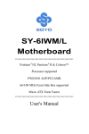
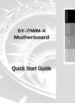
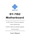
SY-7ISA Motherboard **************************************************** Socket 370 Celeron Processor supported FW82815E AGP/PCI/CNR 66/100/133 MHz Front Side Bus supported ATX Form Factor **************************************************** User's Manual SOYO ™ SY-7ISA Copyright © 2000 by Soyo Computer Inc. Trademarks: Soyo is the registered trademark of Soyo Computer Inc. All trademarks are the properties of their owners. Product Rights: All names of the product and corporate mentioned in this publication are used for identification purposes only. The registered trademarks and copyrights belong to their respective companies. Copyright Notice: All rights reserved. This manual has been copyrighted by Soyo Computer Inc. No part of this manual may be reproduced, transmitted, transcribed, translated into any other language, or stored in a retrieval system, in any form or by any means, such as by electronic, mechanical, magnetic, optical, chemical, manual or otherwise, without permission in writing from Soyo Computer Inc. Disclaimer: Soyo Computer Inc. makes no representations or warranties regarding the contents of this manual. We reserve the right to amend the manual or revise the specifications of the product described in it from time to time without obligation to notify any person of such revision or amend. The information contained in this manual is provided to our customers for general use. Customers should be aware that the personal computer field is subject to many patents. All of our customers should ensure that their use of our products does not infringe upon any patents. It is the policy of Soyo Computer Inc. to respect the valid patent rights of third parties and not to infringe upon or to cause others to infringe upon such rights. Restricted Rights Legend: Use, duplication, or disclosure by the Government is subject to restrictions set forth in subparagraph (c)(1)(ii) of the Rights in Technical Data and Computer Software clause at 252.277-7013. About This Guide: This Quick Start Guide can help system manufacturers and end users in setting up and installing the Motherboard. Information in this guide has been carefully checked for reliability; however, to the correctness of the contents there is no guarantee given. The information in this document is subject to amend without notice. For further information, please visit our Web Site on the Internet. The address is "http://www.soyo.com.tw". Tested To Comply With FCC Standards FOR HOME OR OFFICE USE C FC Edition: September 2000 Version 1.0 7ISA SERIAL 100% ii POST CONSUMER RECYCLED PAPER Table of Contents SY-7ISA Table of Contents CHAPTER 1 MOTHERBOARD DESCRIPTION.....................................1 1-1 1-2 1-3 1-4 1-5 1-6 1-7 1-8 1-9 INTRODUCTION...............................................................1 HANDLING THE MOTHERBOARD ...............................3 ELECTROSTATIC DISCHARGE PRECAUTIONS..........3 SY-7ISA MOTHERBOARD LAYOUT .............................4 SY-7ISA MOTHERBOARD COMPONENTS ..................5 CHIPSET ............................................................................7 I/O INTERFACE CONTROLLER....................................14 HARDWARE MONITOR.................................................16 WAKE ON LAN TECHNOLOGY ...................................16 CHAPTER 2 HARDWARE INSTALLATION.........................................17 2-1 2-2 2-3 2-3.1 PREPARATIONS..............................................................17 UNPACKING THE MOTHERBOARD ...........................18 INSTALLATION GUIDE .................................................19 CPU Installation................................................................ 20 2-3.2 SDRAM Memory Module Installation ............................... 23 2-3.3 Motherboard Connector .................................................... 25 2-3.4 Jumper Setting ................................................................... 41 2-3.5 CMOS Clear (JP5) ............................................................ 44 2-3.6 Power On........................................................................... 44 2-3.7 Debug LEDs ...................................................................... 46 2-3.8 Quick BIOS Setup .............................................................. 47 2-3.10 Troubleshooting at First Start............................................ 49 0 Power Off........................................................................... 53 CHAPTER 3 BIOS SETUP UTILITY .....................................................54 3-1 3-2 3-3 3-4 SOYO COMBO SETUP ...................................................57 STANDARD CMOS SETUP............................................61 ADVANCED BIOS FEATURES ......................................64 ADVANCED CHIPSET FEATURES ...............................68 iii Table of Contents 3-5 3-6 3-7 3-8 3-9 3-10 3-11 3-12 3-13 SY-7ISA INTEGRATED PERIPHERALS.......................................70 POWER MANAGEMENT SETUP..................................75 PNP/PCI CONFIGURATION SETUP..............................79 PC HEALTH STATUS......................................................82 LOAD FAIL-SAFE DEFAULTS ......................................84 LOAD OPTIMIZED DEFAULTS.....................................85 SUPERVISOR PASSWORD ............................................86 USER PASSWORD ..........................................................87 IDE HDD AUTO DETECTION .......................................88 CHAPTER 4 DRIVERS INSTALLATION ..............................................90 CHAPTER 5 SIGMATEL AUDIO DRIVER INSTALLATION ..............94 CHAPTER 6 INTEL 815 VGA DRIVERS INSTALLATION .................96 iv Motherboard Description SY-7ISA Chapter 1 MOTHEBOARD DESCRIPTION 1-1 INTRODUCTION Ø Ø The SY-7ISA AGP/PCI/CNR Motherboard is a high-performance Socket 370 processor supported Micro ATX form-factor system board. SY-7ISA uses the FW82815E Chipset technology and supports Socket 370 processors. This Motherboard is fully compatible with industry standards Supports Intel ®FC-PGA processors - FSB 66MHz: Celeron(400-700MHz) - FSB 100MHz: Pentium ® III (500E-850MHz) - FSB 133MHz: Pentium ® III (533-933MHz) Supports 66/100/133 MHz Front Side Bus Frequency Ø Auto-detect CPU voltage Ø PC99, ACPI Ø Ultra DMA33/66/100 (ATA 33/66/100) Ø Ø Supports Wake-On-LAN (WOL) Support PC-100 and PC-133 SDRAM Ø Supports ACPI Suspend Indicator Ø Power-on by modem, alarm and PS/2 Keyboard Ø Power failure resume Ø Supports Suspend to RAM Ø Supports onboard hardware monitoring and includes Hardware Doctor ™utility Ø Fan speed control Ø Easy CPU settings in BIOS with the “SOYO COMBO Setup” Ø Support display cache interface (AIMM card) multiplexed on the AGP interface -133MHz SDRAM interface only -4MB max addressable 1 Motherboard Description SY-7ISA Ø Battery Low voltage Detect Ø Supports multiple-boot function Ø AGP 2.0 Compliant; AGP Universal Connector supports: - 1.5V and 3.3V AGP cards - 1X/2X/4X data transfer Ø Supports Communication Networking Riser Slot (CNR 1.0 compliant) * Ø Smart Card Reader - Compliant with Personal Computer Smart Card¡ ]PC/SC¡ W ^ orking Group standard - Compliant with smart card¡ ]ISO 7816¡ ^protocols - Supports card present detect - Supports Smart Card insertion power-on feature Ø 3 x DIMM slots for SDRAM memory Ø 1 x 32-bit AGP slot Ø 6 x 32-bit bus master PCI slots Ø 4 x USB ports onboard Ø 1 x IrDA port Ø ATX power connector * If the user wants to use a Modem Riser card (MR) make sure to use a Secondary mode MR, PRIMARY mode MRs are NOT Supported. 2 Motherboard Description 1-2 SY-7ISA HANDLING THE MOTHERBOARD To avoid damage to your Motherboard, follow these simple rules while unpacking: Ø Before handling the Motherboard, ground yourself by grasping an unpainted portion of the system's metal chassis. Ø Remove the Motherboard from its anti-static packaging. Hold the Motherboard by the edges and avoid touching its components. Ø Check the Motherboard for damage. If any chip appears loose, press carefully to seat it firmly in its socket. Warning: Do not apply power if the Motherboard appears damaged. If there is damage to the board, contact your dealer immediately. 1-3 ELECTROSTATIC DISCHARGE PRECAUTIONS Make sure to ground yourself before handling the Motherboard or other system components. Electrostatic discharge can easily damage the components. Note that you must take special precautions when handling the Motherboard in dry or air-conditioned environment. To protect your equipment from electrostatic discharge, take the following precautions: Ø Do not remove the anti-static packaging until you are ready to install. Ø Ground yourself before removing any system component from its protective anti-static packaging. (To ground yourself, grasp the expansion slot covers or other unpainted portions of the computer chassis.) Ø Frequently ground yourself while working or use a grounding strap. Ø Handle the Motherboard by its edges and avoid touching its components. 3 Motherboard Description SY-7ISA 1-4 SY-7ISA MOTHERBOARD LAYOUT PS/2 KB PS/2 Mouse Connector Connector 3 1 ATX Power JP1 USB 1 JP6 JP7 USB 2 1 2 1 1 3 3 CJ1 CJ2 1 2 PRT COM A IDE 2 IDE 1 VGA JOYSTICK 1 3 LINE-OUT CPUFAN LINE-IN CDIN1 DIMM3 4 DIMM1 1 DIMM2 AGP Slot MIC JACK FDC1 PCI#1 Intel Sigmatel STAC9721 PCI#2 JP10 PCI#3 WOL Header JP5 ITE IT8712F-A PCI#4 CMOS Clear Jumper 1 Power LED Reset LED1 LED2 LED3 LED4 PCI#5 3V Lithium Battery 1 2 JP9 PCI#6 SYSFAN LED5 1 2 JP8 Back Panel CNR1 2 14 1 13 SMCARDCN 1 SY-7ISA Platform 4 2 5 SIRCON PWRBT Keylock STR LED HDD LED Speaker 10 JP22 1 9 USB3_4 Motherboard Description SY-7ISA 1-5 SY-7ISA MOTHERBOARD COMPONENTS 5 Motherboard Description A B C D E F G H I J K L M N O P Q R S T U V W X Y Z AA AB AC AD AE AF AG SY-7ISA CPU Frequency Settings Jumper Enable/Disable Power-On by Keyboard Jumper Socket 370 Connector 32-bit AGP slot Intel FW82815 Chip ATX Power Supply Connector DIMM Bank CPU Frequency Settings Jumper Bus Mastering E-IDE/ATAPI Ports Floppy Disk Drive (FDD) Intel FW82801 Chip CMOS Clear Jumper Wake-On-LAN( WOL) Header Chassis Cooling Fan Connector Front panel connectors SPEAKER OPTION Setting Jumper Intel 82802AB 4MB FWH USB Connector FWH Boot Block Write-Protect Setting Jumper Serial Infrared (IrDA) Device Header 5V Stand-by indicator LED (LED 5) 3V Lithium Battery System Fan Connector 32-bit PCI Mastering Slots Smart Card Reader Connector Communication Networking Riser Slot CNR MR Card-CODEC OPTION Setting Jumper Debug LED ITE IT8712F-A Chip AC97 Codec Chip CPU Cooling Fan Connector CD-IN Connector Back panel Connectors 6 Motherboard Description SY-7ISA 1-6 CHIPSET The Intel ® 815E Chipset is a high-flexibility chipset designed to extend from the basic graphics/multimedia PC platform up to the mainstream performance desktop platform. The chipset consists of a Graphics and Memory Controller Hub (Intel ® 815 GMCH), an I/O Controller Hub2 (ICH2) for the I/O subsystem, and a Firmware Hub(FWH). The Intel ® 815 GMCH integrates a system memory SDRAM controller that supports a 64-bit 100/133 MHz SDRAM array. The Intel ® 815E GMCH integrates a Display Cache SDRAM controller that supports a 32-bit 133MHz SDRAM array for enhanced integrated 2D and 3D graphics performance Multiplexed with the display cache interface is an AGP controller interface to enable graphics configuration and upgrade flexibility with the Intel ® 815 chipset. The AGP interface and the internal graphics device are mutually exclusive. When the AGP port is populated with an AGP graphics card the integrated graphics is disabled and thus the display cache interface is not needed. 1-6.1 The Intel ® 815E Chipset System The Intel ® 815E Chipset uses a hub architecture with the Intel ® 815E GMCH as the host bridge hub and the 82801BA I/O Controller Hub2(ICH2) as the I/O hub. The ICH2 is a highly integrated multifunctional I/O Controller Hub that provides the interface to the PCI Bus and integrates many of the functions needed in today’s PC platforms. The Intel ® 815EE GMCH and ICH2 communicate over a dedicated hub interface. 82801BA(ICH2) functions and capabilities include: l PCI Rev2.2 compliant with support for 33MHz PCI operations l ICH2 supports up to 6 PCI/Req/Gnt pairs l Integrated System Management Controller 7 Motherboard Description l SY-7ISA l Enhanced DMA Controller, Interrupt Controller & Timer Functions Bus Master IDE controller – Supports Ultra ATA/100 l USB host interface with support for 4 USB ports l AC’97 2.1 interface l Low Pin Count (LPC) interface l Firmware Hub(FWH)interface support l Alert On LAN l SIM Bus controller l I/O APIC l Upstream accelerated hub architecture interface for access to the GMCH 1-6.2 Intel® 815E GMCH Overview The Intel ® 815E GMCH functions and capabilities include: l Support Uni-processor system l 64-bit AGTL+ based System Bus Interface at 66/100/133 MHz l l 32-bit Host Address Support 64-bit System Memory Interface with optimized support for SDRAM at 100/133 MHz l Integrated 2D & 3D Graphics Engines l Integrated H/W Motion Compensation Engine l Integrated 230 MH DAC l Integrated Digital Video Out Port l 133MHz Display Cache l AGP 1X/2X/4X Controller 1-6.3 Host Interface The host interface of the Intel® 815E GMCH is optimized to support the Intel ® Pentium III processor and Intel ® Celeron ™ Processor in the FCPGA package. The Intel ® 815E GMCH implements the host address, control, and data bus interfaces within a single device. The Intel ® 815E GMCH supports a 4-deep in-order queue(i.e., supports pipelining of up to 4 outstanding transaction 8 Motherboard Description SY-7ISA requests on the host bus). Host bus addresses are decoded by the Intel ® 815E GMCH for accesses to system memory, PCI memory and PCI I/O (via hub interface), PCI configuration space and Graphics memory. The Intel ® 815E GMCH takes advantage of the pipelined addressing capability of the pipelined addressing capability of the processor to improve the overall system performance. The Intel ® 815E GMCH supports the 370-pin socket processor. *370-pin socket (PGA370). The PGA370 is a zero insertion force (ZIF) socket that a processor in the FCPGA package will use to interface with a system board. 1-6.4 System Memory Interface The Intel ® 815E GMCH integrates a system memory controller that supports a 64-bit 100/133 MHz SDRAM array. The only DRAM type supported is industry standard Synchronous DRAM (SDRAM). The SDRAM controller interface is fully configurable through a set of control registers. The Intel ® 815E GMCH supports industry standard 64-bit wide DIMMs with SDRAM devices. The thirteen multiplexed address lines. SMAA[12:0], along with the two bank select lines, SBS[1:0], allow the Intel ® 815E GMCH to support 2M, 4M, 8M, 16M, and 42M x64 DIMM. Only asymmetric addressing is supported. The Intel ® 815E GMCH has 6 SCS# lines (2 copies of each for electrical loading), enabling the support of up to six 64-bit rows of SDRAM. The Intel ® 815E GMCH targets SDRAM with CL2 and CL3 and supports both single and double-sided DIMMs. Additionally, the Intel ® 815E GMCH also provides a 1024 deep refresh queue. The Intel ® 815E GMCH can be configured to keep up to 4 page op[en within the memory array. Pages can be kept open in any one bank of memory. SCKE[4:0] is used in configurations requiring powerdown mode for the SDRAM. 9 Motherboard Description SY-7ISA 1-6.5 Multiplexed AGP and Display Cache Interface The Intel ® 815E GMCH multiplexes an AGP interface with a display cache interface for internal 3D graphics performance improvement. The Display Cache is used only in the internal graphics. When an AGP card is installed in the system, the Intel ® 815E GMCH internal graphics will be disabled and the AGP controller will be enabled. 1-6.5.1 AGP Interface A single AGP connector is supported by the Intel ® 815E GMCH AGP interface. The AGP buffers operate in one of two selectable modes in one of two selectable modes in order to support the AGP Universal Connector: 1) 3.3V drive, not 5 volt safe – This mode is compliant to the AGP 1.0 and 2.0 specs. 2) 1.5V drive, not 3.3 volt safe – This mode is compliant with the AGP 2.0 spec. The following table shows the AGP Data Rate and the Signaling Levels supported by the GMCH: Data Rate 1x AGP 2x AGP 3x AGP Signaling Level 1.5V 3.3V Yes Yes Yes Yes Yes No The AGP interface supports 4x AGP signaling. AGP semantic (PIPE# or SBA[7:0]) cycles to SDRAM are not snooped on the host bus. AGP FRAME# cycles to SDRAM are snooped on the host bus. The GMCH supports PIPE# or SBA[7:0] AGP address mechanisms, but not both simultaneously. Either the PIPE# or the SBA[7:0] mechanism must be selected during system initialization. High priority accesses are supported. Only memory writes form the hub interface to AGP are allowed. No transactions from AGP to the hub 10 Motherboard Description SY-7ISA interface are allowed. 1-6.5.2 AIMM Card Interface Display Cache Interface multiplexed on the AGP interface: l 32-bit data interface l 133 MHz SDRAM interface only l Flexible AGP In-Line Memory Module (AIMM) Implementation l Support for 2 1Mx16, or 1 2Mx32 on AIMM card l 4MB max adderssable 1-6.5.3 Display Cache Interface The Intel ® 815E GMCH support a Display Cache SDRAM controller with a 32-bit 133 MHz SDRAM array. The DRAM type supported is industry standard Synchronous DRAM (SDRAM) like that of the system memory. The local memory SDRAM controller interface is fully configurable through a set of control registers. 1-6.6 Hub Interface The hub interface is a private interconnect between the Intel® 815E GMCH and the ICH2. 1-6.7 Intel® 815E GMCH Integrate Graphics Support The Intel ® 815E GMCH includes a highly integrated graphics accelerator. Its architecture consists of dedicated multi-media engines executing in parallel to deliver high performance 3D, 2D and motion compensation video capabilities. The 3D and 2D engines are managed by a 3D/2D pipeline preprocessor allowing a sustained flow of graphics data to be rendered and displayed. The deeply pipelined 3D accelerator engine provides 3D graphics quality and performance via per-pixel 3D rendering and parallel data paths which allow each pipeline stage to simultaneously operate on different primitives or portions of the same primitive. The Intel ® 815E GMCH graphics accelerator engine supports perspectivecorrect texture mapping, trilinear and anisotropic Mip-Map filtering, Gouraud shading, alpha-blending, fogging and Z-buffering. A rich 11 Motherboard Description SY-7ISA set of 3D instructions permit these features to be independently enabled or disabled. For the Intel ® 815E GMCH, a Display Cache (DC) can be used for the Z-buffer is located in system memory. The Intel ® 815E GMCH integrated graphics accelerator’ s 2D capabilities include BLT and arithmetic STRBLT engines, a hardware cursor and an extensive set of 2D registers and instructions. The high performance 64-bit BitBLT engine provides hardware acceleration for many common Windows operations. In addition to its 2D/3D capabilities, the Intel ® 815E GMCH integrated graphics accelerator also supports full MPEG-2 motion compensation for software-assisted DVD video playback. 12 Motherboard Description SY-7ISA 1-6.8 IDE Support The motherboard has two independent bus-mastering PCI IDE interfaces. These interfaces support PIO Mode3, PIO Mode 4, PIO Mode 5 ATAPI devices (e.g., CD-ROM), and Ultra DMA 33/66/100 synchronous-DMA mode transfers. The BIOS supports logical block addressing (LBA) and extended cylinder head sector (ECHS) translation modes. The BIOS automatically detects the IDE device transfer rate and translation mode. Programmed I/O operations usually require a substantial amount of processor bandwidth. However, in multitasking operating systems, the bandwidth freed by bus mastering IDE can be devoted to other tasks while disk transfers are occurring. The motherboard also supports laser servo (LS-120) drives. LS-120 technology allows the user to perform read/write operations to LS-120 (120MB) and conventional 1.44MB and 720KB diskettes. An optical servo system is used to precisely position a dual-gap head to access the diskett’s 2,490 tracks per inch (tpi) containing up to 120 MB of data storage. A conventional diskette uses 135 tpi for 1.44 MB of data storage. LS-120 drivers are ATAPI-compatible and connect to the motherboard’s IDE interface. (LS-120 drives are also available with SCJSI and parallel port interfaces.) Some versions of Windows 95 and Windows NT operating systems recognize the LS-120 drive as a bootable device in both 120 MB and 1.44 MB mode. Connection of an LS-120 drive and a standard 3.5-inch diskette drive is allowed. The LS-120 drive can be configured as a boot device if selected as Drive A in the BIOS setup program. ¿ Note If you connect at LS-120 drive to an IDE connector and configure it as the :boot: drive and configure a standard 3.5-inch diskette drive as a “B” drive, the standard diskette drive is not seen by the operating system. When the LS-120 drive is configured as the “boot: device, the system will recognize it as both the A and B drive 13 Motherboard Description SY-7ISA 1-6.9 Real-Time Clock The real-time clock supports 256 bytes of battery-backed CMOS SRAM. Hardware implementation to indicate century rollover. 1-7 I/O INTERFACE CONTROLLER The motherboard uses the ITE IT8712F-A I/O controller which features: l Single diskette drive interface l Two serial ports l FIFO supports on both serial and diskette interfaces l One parallel port with Extended Capabilities Port (ECP) and Enhanced Parallel Port (EPP) support l PS/2 style mouse and keyboard interfaces l PCI PME interface l Intelligent auto power management, including: Ø Shadowed write-only registers for ACPI compliance Ø Programmable wake-up event interface The Setup program provides configuration option for the I/O controller. 1-7.1 Serial Ports The motherboard has one 9-pin D-Sub serial port connector located on the back panel. The NS16C5450-compatible UARTs support data transfers at speeds up to 115.2 Kbits/sec with BIOS support. 1-7.2 Parallel Port The connector for the multimode bi-directional parallel port is a 25-pin DSub connector located on the back panel of the motherboard. In the Setup program, there are four options for parallel port operation: l Compatible (standard mode) l Bi-directional (PS/2 compatible) l Bi-directional EPP. A driver from the peripheral manufacturer is required for operation. See Section 6.2 for EPP compatibility. l Bi-directional high-speed ECP 1-7.3 Diskette Drive Controller The I/O controller is software compatible with the 82077 diskette drive controller and supports both PC-AT and PS/2 modes. In the Setup 14 Motherboard Description SY-7ISA program, the diskette drive interface can be configured for the following diskette drive capacities and sizes. l 360 KB, 5.25-inch l 1.2 MB, 5.25-inch l 720 KB, 3.5-inch l 1.2 MB. 3.5-inch (driver required) l 1.25-1.44 MB, 3.5-inch l 2.88 MB, 3.5-inch 1-7.4 PS/2 Keyboard and Mouse Interface PS/2 keyboard and mouse connectors are located on the back panel of the motherboard. The +5 V lines to keyboard and mouse connectors are protected with a fuse that prevents motherboard components from being damaged when an over-current condition occurs. ¿ Note The mouse and keyboard can be plugged into either PS/2 connector. Power to the computer should be turned off before a keyboard or mouse is connected or disconnected. The keyboard controller contains code, which provides the traditional keyboard and mouse control functions, and also supports Power On/Reset password protection. Power On/Reset password can be specified in the BIOS Setup program. The keyboard controller also supports the hot-key sequence <Ctrl><Alt><Del>, software reset. This key sequence resets the computer’s software by jumping to the beginning of the BIOS code and running the Power On Self Test (POST). 1-7.5 Infrared Support The IR connection can be used to transfer files to or from portable devices like laptops, PDAs, and printers. 15 Motherboard Description SY-7ISA 1-8 HARDWARE MONITOR The optional hardware monitor subsystem provides low-cost instrumentation capabilities. The features of the hardware monitor subsystem include: Ø An integrated ambient temperature sensor Ø Fan speed sensors, which monitor the fan 1 and fan 2 connectors Ø Power supply voltage monitoring to detect levels above or below acceptable values When suggested ratings for temperature, fan speed, or voltage are exceeded, an interrupt is activated. The hardware monitor component connects to the SMBus. 1-9 WAKE ON LAN TECHNOLOGY Wake on LAN technology enables remote wakeup of the computer through a network. Wake on LAN technology requires a PCI add-in network interface card (NIC) with remote wakeup capabilities. The remote wakeup connector on the NIC must be connected to the onboard Wake on LAN technology connector. The NIC monitors network traffic at the MII interface; upon detecting a Magic Packet, the NIC asserts a wakeup signal that powers up the computer. To access this feature uses the Wake on LAN technology connector. * CAUTION For Wake on LAN, the 5-V standby line for the power supply must be capable of delivering +5V ±5 % at 720 mA. Failure to provide adequate standby current when implementing Wake on LAN can damage the power supply. 16 Hardware Installation SY-7ISA Chapter 2 HARDWARE INSTALLATION Congratulations on your purchase of SY-7ISA Motherboard. You are about to install and connect your new Motherboard. Note: Do not unpack the Motherboard from its protective antistatic packaging until you have made the following preparations. 2-1 PREPARATIONS Gather and prepare all the following hardware equipment to complete the installation successfully: 1. Socket 370 processor with built-in CPU cooling fan. Note: This Motherboard supports non-boxed type CPUs. 2. DIMM memory module(s) 3. Computer case and chassis with adequate power supply unit 4. Monitor 5. PS/2 Keyboard 6. Pointing Device (PS/2 mouse) 7. Speaker(s) (optional) 8. Disk Drives: HDD, CD-ROM, Floppy drive … 9. External Peripherals: Printer, Plotter, and Modem (optional) 10. Internal Peripherals: Modem and LAN cards (optional) 17 Hardware Installation 2-2 SY-7ISA UNPACKING THE MOTHERBOARD When unpacking the Motherboard, check for the following items: u The SY-7ISA FW82815E AGP/PCI/CNR Motherboard u This Quick Start Guide u The Installation CD-ROM u SOYO Bonus Pack CD-ROM u One IDE Device ATA 100 Flat Cable u One Floppy Disk Drive Flat Cable Warning: Do not unpack the Motherboard from its anti-static packaging until you are ready to install it. Like most electronic equipment, your Motherboard may be damaged by electrostatic discharge. To avoid permanent damage to components ground yourself while working by using a grounding strap. Otherwise, ground yourself frequently by touching the unpainted portion of the computer chassis to drain the static charges. Handle the Motherboard carefully, holding it by the edges. You are now ready to start the installation. 18 Hardware Installation SY-7ISA 2-3 INSTALLATION GUIDE We will now begin the installation of the Motherboard. Please follow the step-by-step procedure designed to lead you to a complete and correct installation. Warning: Turn off the power to the Motherboard, system chassis, and peripheral devices before performing any work on the Motherboard or system. BEGIN THE INSTALLATION 19 Hardware Installation SY-7ISA 2-3.1 CPU Installation To perform the installation of your new SY-7ISA Motherboard, follow the steps below: Mark your CPU Frequency: Record the working frequency of your FC-PGA CPU that should be clearly marked on the CPU cover. FSB 66MHz 400MHz (66 x 6.0) 433MHz (66 x 6.5) 466MHz (66 x7.0) 500MHz (66 x7.5) 533MHz (66 x 8.0) 566MHz (66 x 8.5) 600MHz (66 x 9.0) 633MHz (66 x 9.5) 667MHz (66 x 10.0) 700MHz (66 x 10.5) FSB 100MHz 500MHz (100 x 5.0) 550MHz (100 x 5.5) 600MHz (100 x 6.0) 650MHz (100 x 6.5) 700MHz (100 x 7.0) 750MHz (100 x7.5) 800MHz (100 x 8.0) 850MHz (100 x 8.5) 667MHz (133 x 5.0) 733MHz (133 x 5.5) 800MHz (133 x 6.0) 866MHz (133 x 6.5) 933MHz (133 x 7.0) 1000MHz (133 x 7.5) FSB 133MHz 533MHz (133 x 4.0) 600MHz (133 x 4.5) This Motherboard is designed to support processors with 66/100/133 MHz FSB. CPU Mount Procedure: To mount the processor that you have purchased separately, follow these instructions. 1. Lift the socket handle up to a vertical position. 20 Hardware Installation 2. SY-7ISA Align the blunt edge of the CPU with the matching pinhole distinctive edge on the socket. 3. Seat the processor in the socket completely and without forcing. 21 Hardware Installation 4. SY-7ISA Then close the socket handle to secure the CPU in place. Remember to connect the CPU Cooling Fan to the appropriate power connector on the Motherboard. The fan is a key component that will ensure system stability. The fan prevents overheating, therefore prolonging the life of your CPU. 22 Hardware Installation SY-7ISA DIMM 3 DIMM 2 DIMM 1 2-3.2 SDRAM Memory Module Installation Your board comes with two DIMM sockets, providing support for up to 512MB of main memory using unbuffered and Non-ECC DIMM modules from 32MB to 512MB, No reqistered DIMM support. Supports up to 3 Double sided DIMMs at 100MHz system memory. Supports up to 2 double sided or 3 single sided DIMMs a 133MHz system memory bus. On this motherboard, DRAM speed can be set independent from the CPU front side bus speed. Depending on the DRAM clock speed setting in the BIOS setup. 84 1 1 84 23 Hardware Installation SY-7ISA Memory Configuration Table Number of Memory Modules DIMM 1 DIMM 2 DIMM 3 Single-Side PC100/PC133 PC100/PC133 PC100/PC133 RAM Type Double-Side PC100 PC100 PC133 PC133 PC133 Memory Module Size (MB) 32/64/128/256/512 MB 24 P100 PC133 Hardware Installation SY-7ISA 2-3.3 Motherboard Connector 2-3.3.1 IDE Device Installation (HDD, CD-ROM) IDE 2 IDE 1 Pin -1 Secondary Primary IDE IDE This Motherboard offers two primary and secondary IDE device connectors (IDE1, IDE2.) It can support up to four high-speed HDD or CD-ROM. Connect one side of the 80-pin flat cable to the IDE device (HDD or CDROM) and plug the other end to the primary (IDE1) or secondary (IDE2) directionally keyed IDE connector on the Motherboard. This Motherboard can support up to four ATA 33/66/100 IDE devices. 80-Conductor ATA 66 Flat Cable 1 80-pin 79 1 79 25 Hardware Installation SY-7ISA 2-3.3.2 Floppy Drive Installation Pin -1 FDC Floppy Drive Connector The system supports 5 possible floppy drive types: 720 KB, 1.2 MB, 1.44 MB, 2.88 MB, and LS-120. In addition, this Motherboard supports a 3-mode (720KB/1.2MB/1.44MB) floppy commonly used in Japan. Connect one side of the 34-pin flat cable to the floppy drive and plug the other end to the floppy drive connector on the Motherboard. This Motherboard can support up to 2 floppy drives. 1 33 1 33 26 Hardware Installation SY-7ISA 2-3.3.3 Front Panel Connections + Reset Power LED _ PWRBT Key Lock + _ + _ STR LED HDD LED + Speaker _ Plug the computer case's front panel devices to the corresponding headers on the Motherboard. 1. Power LED & KeyLock Plug the Power LED cable into the 5-pin Keylock header. Some systems may feature a KeyLock function with a front panel switch for enabling or disabling the keyboard. Connect the KeyLock switch to the 5-pin Keylock header on the Motherboard. Please install according to the following pin assignment: pin 1,3 are for Power LED and pin 4,5 are for Keylock. Power LED Pin Assignment _ + +5V Key Lock Pin Assignment NC 1 GND Control Pin 27 GND Hardware Installation SY-7ISA 2. Reset Plug the Reset push-button cable into the 2-pin Reset header on the Motherboard. Pushing the Reset button on the front panel will cause the system to restart the boot-up sequence. Reset Pin Assignment 1 Power Good 3. GND Speaker Attach the 4-pin PC speaker cable from the case to the Speaker header on the Motherboard. Speaker Pin Assignment _ + +5V 4. Speaker out NC NC STR LED The STR LED is connected to the Voltage that