1
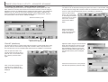
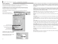
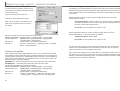
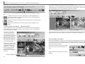
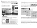
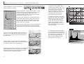
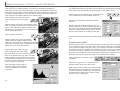
DIMAGE
SCAN DUAL III UTILITY
- ADVANCED
SCANNING
Autoexposure control - More prescan functions
AE area selection
Autoexposure adjusts the scanner exposure to compensate for the density of the
film. To use the autoexposure function with color slides, the auto-expose-for-slides
option must be checked in the preferences box. To use it with color negatives, the
exposure control for negatives must be set to auto in the preferences box (p. 44).
Click the AE-area-selection button
after prescanning the image.
AE area selection allows the use of a small area within the image to determine the
scan exposure. Use AE area selection with high or low key images, or when the film
has been badly exposed.
The AE lock function sets the scanner exposure based on the exposure determined
for a specific prescan with or without the use of AE area selection. This exposure
can be applied to scans of different images. This function is useful when scanning a
series of high and low-key images that have consistent exposures. By locking the
exposure on one frame when scanning a bracket series, the scans of the other
frames will show the exposure difference in the each frame of the series.
Prescan button (p. 37)
Pressing the shift key changes the
dotted cropping frame to the solid
AE area frame. While pressing the
shift key, use the mouse to adjust
and move the AE area. The methods used to manipulate the frame
are the same as the cropping
frame except that the shift key
must be held, see manual cropping
section on page 38.
Place the AE area over the section
of the image to be used to determine the exposure. Usually placing the area over
the subject of the picture will produce excellent results. The area should represent
on average the mid-tone of the image.
Preference button (p. 44)
Click the prescan button to view the effect on the exposure. AE area selection can
be canceled by pressing the AE-area-selection button again.
AE lock
After making a prescan or setting the exposure of the reference image with the AE-area-selection function, click the
AE lock button to fix the scanner’s exposure.
Select another image and click the prescan button to view the result with the set
exposure. To cancel the AE lock, click the AE lock button again. The prescan and
final scan will be made with the locked exposure setting until the AE lock is canceled.
AE-area-selection button
AE lock button
50
51
DIMAGE
SCAN DUAL III UTILITY
- ADVANCED
SCANNING
Focusing the scanner - More prescan functions
Manual focus
Use the focusing functions if the film is warped or curled. Three options are available: autofocus, Point AF, and manual focus. Autofocus uses the center of image to
determine the focus is activated with the autofocus-at-scan option in the preferences
dialog box (p. 44). Point AF uses a point specified in the image to determine the
focus. The scanner can also be focused manually using a selected point. Point AF
and manual focus can be used for individual images.
The scanner can be focused manually using the focus meter. For best results, select
an area within the image with contrast or detail. The manual focus functions cannot
focus on a low-contrast image area such as a cloudless or overcast sky.
Preference button (p. 44)
Click the manual-focus
button. The mouse pointer will change to the manual-focus icon. To cancel
the function, click the
manual-focus button
again.
Click on the area of
image to be used for
focus. The focus meter
window will appear.
Point-AF button (p. 52)
Manual-focus button (p. 53)
Point AF (Autofocus)
The point AF focuses on a select point within the image. For best results when using
point AF, select an area within the image with contrast or detail. The point AF function cannot focus on a low-contrast image area such as a cloudless or overcast sky.
Click the point-AF button. The
mouse pointer will change to the
point-AF icon. To cancel the function, click the point-AF button
again.
Click on the area of image to be
used for focus. Autofocus will
begin and a new prescan will be
displayed.
52
Adjust the slider using the mouse until the
black and white bars are at their longest
extension for sharpest focus. The black
bar indicates the change in focus. The
white bar indicates the longest extent of
the black bar and the point of sharpest
focus.
Click OK to set the focus. A new prescan
will start and replace the previous image.
53
DIMAGE
SCAN DUAL III UTILITY
- ADVANCED
SCANNING
Inputting scan settings manually
Settings for the final scan such as input or output resolution and size can be manually made for individual images in the index scan or prescan windows. Once made,
they will remain in effect until changed.
lock. The input-size lock button cannot be used if pixel is selected in the unit list box.
Magnification text box: to set image magnification. This value equals the input resolution divided by the output resolution, or the output size divided by the input size.
The magnification text box cannot be used if pixel is selected in the unit list box.
Scan setting window
Job-name list box
Load Job button
Save Job button
Input-resolution list box
Output-resolution list box
Input-size text boxes
Input-size lock button
Magnification text box
Output-size text boxes
When the input size and output size are unlocked, the input resolution and output
size vary according to the entered magnification value. When the output size is
locked, the input resolution and input size vary according to the entered magnification value. When the input size is locked, the input resolution and output size vary
according to the entered magnification.
Output-size text box: output size is determined by either the cropping frame dimensions or the values entered in the width and height boxes. The width and height of
the output image can be directly entered into the text boxes; the input resolution,
input size, and cropping frame adjust according to the entered dimensions.
Output-size lock button: to lock the output size values.
Unit list box: the input and output size unit can be changed: pixels, millimeters,
centimeters, inches, pica, and points.
Image size display: indicates the file size of the image.
Output-size lock button
Reset button: to initialize all current settings.
Reset button
Unit list box
Image-size display
Input-resolution list box: values can be selected among the drop-down list or be
entered into the box directly. Values between 282 and 2820 dpi can be selected
among the drop-down list. Values between 176 and 2820 can be entered into the
box directly.
Output-resolution list box: values between 36 and 2400 dpi can be selected
among the drop-down list or be entered into the box directly. Output-resolution cannot be entered if pixel is selected in the unit list box.
Input-size text box: input size is determined by either the cropping frame dimensions or the values entered in the width and height boxes. The cropping frame will
adjust to any value entered. Input-size cannot be entered if pixel is selected in the
unit list box.
Input-size lock button: to lock the input values. The cropping frame can be moved,
but not resized while this button is clicked. Clicking the button again releases the
54
About resolution and output size
Resolution can be expressed in dpi (dots per inch). This refers to how many pixels
are placed along one linear inch. A resolution of 350 dpi, which is commonly used in
commercial printing, means that an area of one square inch would use 122,500 pixels. The larger the resolution, the greater the detail in the image. However, as the
resolution increases, so does the file size.
The image resolution depends on the resolution of the output device. A printer with a
resolution of 150 dpi will not be able to print a 300 dpi file any better than a 150 dpi
file; the 300 dpi file will just be four-times larger. Once the output resolution is determined, the input resolution can be calculated from the magnification needed to
match the output.
Input resolution
Output resolution
=
Output size
Input size
=
Magnification factor
For example, to make a 144 mm x 96 mm print at a resolution of 150 dpi from 35mm
film (image size: 36mm x 24mm), the magnification can be calculated by dividing the
print dimensions by the film dimensions: 96 mm / 24 mm = 4 times. The input resolution can be determined from the magnification factor: 150 dpi X 4 = 600 dpi.
55
DIMAGE
SCAN DUAL III UTILITY
- ADVANCED
SCANNING
Scan setting examples
Saving scan settings as a Job
Example 1: setting the scanner output by pixels. This example creates an image
with the pixel dimension of 1024 X 768.
Frequently used scan settings can be saved.
Select pixel from the unit list box. The output-resolution and input-size boxes are deselected.
Enter the dpi resolution for the output size; 1024 for
the width and 768 for the height. Click the output-size
lock button to fix the values; the output-size boxes will
be deselected.
With the settings to be saved in the scan setting window, click the save Job button. The Job-registry dialog box will open.
Select the category in which to save the settings
from the drop-down menu.
Use the mouse to adjust the cropping frame over the
prescan image to define the final scanning area. Click
on the frame of the cropping area to resize the box.
The input resolution will adjust according to the cropping area. Click and drag the center of the area to
move the frame.
The scan settings are complete and the final scan can be made. Once made, scan
settings remain in effect until changed.
Example 2: setting output by print size and output resolution. This example creates
a 148mm X 100mm image to be printed on a 300 dpi printer.
Enter the Job name. Click OK to save the settings. See page 42 to load a Job.
Deleting a Job
A Job file can be deleted. Once deleted, it can not be recovered.
Select millimeters from the unit list box.
Enter the output resolution of the printer in the outputresolution list box: 300.
Click the load Job button.
Enter the output size; 148 for the width and 100 for
the height. Click on the output-size lock button to fix
the values.
Use the mouse to adjust the cropping frame over the
prescan image to define the final scanning area. Click
on the frame of the cropping area to resize the box;
the input resolution will adjust according to the cropping area. Click and drag the center of the area to
move the frame.
Select the Job file to be deleted from the Job
categories in the selection window. Use the following key(s) to delete the selected file:
Windows - delete key
Macintosh - command key + D.
The scan settings are complete and the final scan can
be made. Once made, scan settings remain in effect
until changed.
56
57
DIMAGE
SCAN DUAL III UTILITY
- ADVANCED
Custom Wizard
The Custom Wizard is an automated
scanning routine.
SCANNING
Make any adjustments to the scanner exposure.
Previously saved settings can be loaded. See page
46 for more information. Click the next button to continue.
Insert a film holder into the scanner.
Click the Custom Wizard button.
On the Custom-Wizard-setting dialog box, select New
from the Custom Wizard settings. Click the next button.
If previous Custom Wizard settings have been saved,
they will be displayed in this window. To use any settings, simply select it with the mouse.
Set up the dialog box for the film and holder in use.
Select the frame number(s) of the images to be
scanned. The frame number refers to the frame number of the holder. Settings made in the Custom
Wizard will be applied to all the selected frames.
Click the next button to continue.
Select scanning preferences in the dialog box. Click
the next button to continue.
The Auto Dust Brush (p. 39) and Pixel Polish (p. 40)
functions can be used in the scan. Click the Auto
Dust Brush button to activate the dust-removal function, then set the degree of processing with the slider.
Click the Pixel Polish button to activate the automatic
image-correction function, then specify automatic or
custom corrections. Click the next button to continue.
When 16-bit linear color depth is selected in the preferences window, this screen will not appear.
Select image-correction settings. Click the next button to continue.
Image corrections can be made by loading an imagecorrection Job (p. 68). The auto-setting functions
automatically correct the scanned image: the tone
curve and histogram setting improves color and contrast: the brightness, contrast, and color-balance setting improves contrast and brightness: the hue, saturation, and lightness setting improves saturation.
For information on the preference settings, see page
44. For information on color matching, refer to page
60.
Click the save button to save the Custom Wizard settings. Enter the file name in the save window and
click OK. The next time the Custom Wizard is used,
those settings can be selected in the
Custom Wizard setting dialog box.
Enter scan settings. Click the next button to continue.
Click the start button to begin automatic
scanning.
See pages 42 and 54 for details on Jobs and manual
scan settings. When the window opens, the last scan
settings made will be displayed.
See page 37 for information on auto-cropping. Insideedge cropping is recommended for mounted slides.
The auto-cropping function will take priority over any
scan settings entered.
58
When the scanning is complete, the film holder will be ejected or the APS cassette
in the optional adapter will be rewound automatically. To continue scanning with the
same settings, change the film in the film holder and click the start button. To quit
scanning, click the quit button.
59
DIMAGE
SCAN DUAL III UTILITY
- ADVANCED
SCANNING
Color matching
Each output device (monitor or printer) defines color and contrast differently. To
ensure the output images are reproduced to the original scanned data as accurately
as possible, the color space for both devices must be defined.
The DiMAGE Scan Dual III color matching function matches the scanned color with
specified color spaces. The color matching system can use the monitor’s ICC profile
to display the image as accurately as possible.
Color matching is activated in the preferences box. Color matching increases the
scanning time.
Click the preferences button to
access the color-matching function.
The choice of output color space depends on how the image will be reproduced. For
most home use where the image is displayed on a monitor or printed with a small
printer, sRGB color space is adequate. Other color spaces have been included for
professional and technical applications. For recommendations for color space use,
see page 63.
sRGB: the color space promoted by Hewlett Packard and Microsoft. Since it reflects
the average PC monitor characteristics, it is considered to be the standard for multimedia and Internet usage. sRGB is not suitable for professional prepress applications because of its narrow reproduction range.
Apple RGB: widely used in DTP. It is the standard color space in many common
graphic arts and design applications: Adobe Illustrator, Photoshop, etc.
SMPTE-C: this is the current standard used in television broadcasting in the United
States.
PAL/SECOM: this is the current standard used in television broadcasting in Europe.
ColorMatch RGB: this color space standard has a wide color space and is ideal for
use with Radius Press View monitors, which are commonly used in prepress production.
Adobe RGB: this color space standard is wider than ColorMatch RGB. The extensive color range makes it ideal for prepress use. However, the range is so great that
it includes many colors that cannot be printed with a four-color printing process.
Color-space list box
Color-matching-on check box
Use-ICC-profile check box
ICC-profile text box
Load ICC-profile button
Setting the output color space
Gamut RGB: utilizing the color coordinates of the spectrum, this standard offers an
extremely extensive range of colors. However, most of the colors that can be generated cannot be reproduced on standard computer monitors or by printing technology.
NTSC: the current television broadcasting standard used in Japan.
CIE RGB: this color space is defined by the CIE (Commission Internationale
d`Eclairage).
Monitor RGB: this color space is defined by the monitor’s ICC profile. See setting
the monitor ICC profile section on page 62.
Click the color-matching-on check box.
Select the output color space from the
color-space drop-down menu.
60
61
DIMAGE
SCAN DUAL III UTILITY
- ADVANCED
SCANNING
Setting the monitor ICC profile
Color matching recommendations
The ICC profile for a specific monitor can be
used. Refer to the monitor instruction manual
for the profile name.
The following are recommendations for output color space and monitor ICC-profile
settings with image-processing applications. Some applications have a monitor correction display function which automatically corrects the monitor display to a specific
color space.
Click the use-ICC-profile check box.
Click the load ICC-profile button. The operating
systems file-open dialog box will open.
Open the ICC profile for the monitor in use.
Click OK in the preferences box to set the
ICC profile.
With an application with a monitor correction display function such as Adobe
Photoshop ver.5 or later:
Output Color Space: Select the same color space as set in the application. With Photoshop ver. 5.0 or later, look in the color-setting option in the
file menu for the profile setup window.
ICC Profile: Use the profile for the monitor in use.
With an application without a monitor correction display function such as
Photoshop Elements, or when the function is disabled:
Monitor ICC profiles can be found at the following locations:
Windows 98/98SE/Me: [Windows] folder -> [System] folder -> [Color] folder.
Windows 2000, XP:
[WINNT] folder ->[System32] folder ->[Spool] folder
->[Drivers] folder ->[Color] folder.
Mac OS 8, 9:
[System] folder ->[ColorSync Profile] folder.
Mac OS X:
[/(root)] -> [Library] folder- >[ColorSync] folder - >[Profiles]
folder - > [Displays] folder.
Scanner color profiles
When installing the scanner utility software, scanner color profiles will be automatically installed. These profiles have been included for advanced color matching with
profile-to-profile conversions in sophisticated image-processing or DTP applications.
When using these profiles, the color reproduced may not be the same as the color
matching system in the utility software.
Output Color Space: Monitor RGB
ICC Profile: Use the profile for the monitor in use.
The ICC profile for a specific monitor should be available from the manufacturer.
These may be downloaded from the manufacturer’s web site. See the monitor’s
instruction manual on how to install the ICC profile.
Color monitor ICC profiles can be created with one of the profile creation tools on
the market. They can also be created with the monitor-adjustment-assistant function
installed in a Macintosh operating system, or with Adobe gamma included in Adobe
Photoshop (ver. 5.0 or later) for Windows.
MLTF2840.icc - used with positive film at any color depth other than 16-bit linear
MLTF2840p.icc - used with positive film with 16-bit linear color depth.
The profiles are located in the following locations:
Windows 98/98SE/Me: [Windows] folder -> [System] folder -> [Color] folder.
Windows 2000, XP:
[WINNT] folder ->[System32] folder ->[Spool] folder
->[Drivers] folder ->[Color] folder.
Mac OS 8, 9:
[System] folder ->[ColorSync Profile] folder.
Mac OS X:
[/(root)] -> [Users] folder - > folder with user logon name
- >[Library] folder ->[ColorSync] folder ->[Profiles] folder.
62
63
DIMAGE
SCAN DUAL III UTILITY
-
IMAGE PROCESSING
Image processing tools
Guide to image processing tool
This section contains details on the image-processing tools as well as functions to
view and save image corrections.
There are multiple tools that will result in the same effect. One may be easier or
more flexible than another. The most suitable tool for a specific job will depend not
only on the required results but also the experience of the operator; all changes
made with any of the palettes can be reset or undone (p. 66).
Main window and image-correction tab
The prescan image or a selected index image can be displayed in the correction window by simply clicking the image-correction tab. If the image has not been prescanned, a prescan will be made automatically.
Index scan button (p. 33)
Prescan button (p. 37)
Scan button (p. 43)
Tool bar
RGB display
The RGB display will show the color
values for any point on the image.
Simply place the mouse pointer on
the image area
Current RGB values
to see the RGB
values of that
Original RGB values
point. Pressing
the shift key
(Windows) or
command key
(Macintosh) will
display the
CMY values.
Display area
Fit-to-window button (p. 35)
Comparison display button (p. 67)
Save image-correction Job button (p. 67)
Load image-correction Job button (p. 68)
Snapshot button (p. 66)
Reset-all button (p. 66)
Redo button (p. 66)
Undo button (p. 66)
Unsharp mask button (p. 80)
Selective-color button (p. 79)
Variation button (p. 69)
Hue, saturation, and lightness button (p. 81)
Brightness, contrast, and color-balance button (p. 70)
Tone-curve/histogram button (p. 71)
The utility window can be resized by clicking and dragging the bottom right corner. If
any changes are made to the image, the image-correction tab will be highlighted in
red.
64
Tools and functions
Effects
Brightness
Contrast
Color balance
Saturation
Brightness
Brightness, contrast, and color-balance palette: correcContrast
tions can be made easily with the use of sliders (p. 70).
Color balance
Tone-curve and histogram palette: advanced image processing tool using a graphic representations of the lumiBrightness
nance levels and distribution within the image. Adjustments Contrast
can be made to highlights, mid-tones, and shadows in the Color balance
color and luminance channels (p. 71-78).
Selective-color palette: advanced tool to make precise
Changes to a
adjustments to a specific color group without influencing
specific color.
any of the other color groups in the image (p. 79).
Variation palette: a simple image processing tool.
Corrections are made by choosing the best image from a
group of slightly corrected samples (p. 69).
Unsharp mask: advanced tool to sharpen edges and detail
Sharpness
in the image (p. 80).
Hue, saturation, and lightness palette: advanced and
creative image-processing tool to change image color and
brightness (p. 81).
Hue
Saturation
Lightness
Pixel Polish: an image-enhancement tool which makes automatic corrections or custom correction using straightforward parameters (p. 40).
Auto Dust Brush: an automatic dust-removal tool which reduces the affect
of dust on the film (p. 39).
Image processing glossary
Brightness/Lightness: The intensity of image luminance or how light or dark a picture is.
Contrast:
Affects the difference between highlights and shadows; an increase
in contrast makes the light tones brighter and dark tones darker.
Adjustment to contrast can affect the apparent image sharpness.
Color balance:
The relative strength of the overall color of an image. Color balancing makes an image with a color cast appear natural.
Saturation:
The vividness of the colors.
Hue:
A distinct color within a color space. Changes to hue reassign colors depending on their position in the color space.
Sharpness:
The clarity of image detail.
65
DIMAGE
SCAN DUAL III UTILITY
-
IMAGE PROCESSING
Undoing and redoing image corrections
Comparing pre and post correction images
Clicking the comparison display button divides the image display area in two. The
original image is on the left and the corrected image is on the right. To display the
corrected image only, click the comparison display button again.
The undo, redo, and reset-all buttons only affect tools used in the image-correction
tab.
Click the undo button to cancel the last image correction applied to the
image. The number of image corrections that can be undone depends on
the computer memory capacity.
Click the redo button to reapply the last image correction canceled with the
undo button.
Click the reset-all button to cancel all image corrections applied to the
image.
Tracking image corrections - Snapshot button
Image corrections can be stored temporarily as a thumbnail next to the displayed
image. Simply click the snapshot button on the tool bar to create a thumbnail with
the current image corrections.
To return to a previous
image correction, click on
the corresponding snapshot thumbnail. The thumbnail image will replace the
displayed image. The number of snapshots that can
be made is only limited by
the computer memory.
To delete a snapshot, click
on the thumbnail and press
the keyboard delete key
(Windows), or command
and D key (Macintosh).
The thumbnails will be
deleted when the software
is closed.
Original image
Corrected image
Changes made with the scroll bars on one image will be applied to the other. Using
the fit-to-window button automatically resizes both images to fit the display area.
Saving image corrections
All corrections applied to an image can be saved as an image-correction Job. The
Job can be loaded into the utility at any time and applied to different images. This is
a time-saving function when a large number of images need too be processed with
the same correction settings.
Click the save image-correction Job button
to save the current image-correction settings.
Enter the Job name. Click OK to save the
settings.
Snapshot display area
66
67
DIMAGE
SCAN DUAL III UTILITY
-
IMAGE PROCESSING
Loading image-correction Jobs
Variation palette
Display the image to be corrected in the imagecorrection window. Click the load image-correction Job button to load a saved image-correction
setting.
The variation palette allows an image to be corrected by comparing it to other slightly corrected images surrounding it. This is an easy method to correct images for individuals who are inexperienced in image processing or photofinishing.
Click on an image-correction Job thumbnail to
select it. Click OK to apply the Job to the displayed image. Jobs are loaded into the snapshot
display area. Multiple Jobs can be loaded.
Click the variation button to display the palette.
Click the arrow next to the variation list box (1) to select the image quality to be corrected: color balance, brightness and contrast, or saturation. Each variation palette
shows the current image in the center with corrected sample images displayed
around it.
Variation list box
Variation-step slide and text box
Display-limit check box
1
Close button
2
Snapshot display area
Complementary colors
Reset button
Knowing the complementary colors is very important in color balancing. If the
image has a specific color cast, either subtracting the color or adding its complementary color will create a natural looking image.
RED
GREEN
If the image is too
Decrease the amount of red.
Decrease the amount of green.
BLUE
Decrease the amount of blue.
CYAN
Increase the amount of red.
MAGENTA
YELLOW
Increase the amount of green.
Increase the amount of blue.
The introduction to color section on page 90 covers basic information about
RGB and CMY, as well as more on complementary colors.
68
Click the best image among the frames (2). The selected image becomes the new
center surrounded by a set of new images and the change is applied to the prescan
image. This procedure can be repeated until the desired correction is obtained. Click
the reset button to cancel any changes.
The difference between the images can be changed. Drag the variation-step slider,
or enter a value into the text box to set the degree of correction. The initial setting is
10. The correction step can be set between 1 and 20.
Checking the display-limit check box will indicate when any of the image values
exceed 0 (black limit) or 255 (white limit) with the complementary color. For example, if the blue area of the image exceeds those values, the limit is displayed with
the complementary color, yellow.
Click the close button to close the palette and apply any image corrections.
69
DIMAGE
SCAN DUAL III UTILITY
-
IMAGE PROCESSING
Brightness, contrast, and color balance palette
Tone curve and histogram corrections
Click the brightness, contrast, color-balance
button to display the palette.
The tone curve is a graphic representation of the brightness and color
levels of the image. The bottom axis
is the 256 levels of the original
image (input data) from black to
white. The vertical axis is the corrected image (output data) with the
same scale from top to bottom.
Changes will be reflected in the displayed image and
in the graph at the top of the palette. The horizontal
axis of the chart indicates the original image values
and the vertical axis the new values. Click the reset
button to cancel any changes.
Clicking the auto-setting button corrects the brightness
and contrast automatically without affecting the color
balance. Click the reset button to cancel the changes.
Output
Drag the brightness, contrast, or color sliders, or enter
specific values in the corresponding text box to make
corrections. Dragging each slider to the right or
inputting a positive number in the text box increases
the brightness, contrast, and color.
Highlights
The bottom left portion of the graph
represents the dark colors and shadow areas of the image. The middle
section represents the mid-tones:
skin, grass, blue sky. The top right
section is the highlights: clouds,
lights. Changing the tone curve can
affect the brightness, contrast, and
color of the image.
Mid-tones
Shadows
Input
Shadows
Simply making everything darker with the brightness
controls creates a muddy image - the snow and sky are
a dull gray and there are no strong blacks.
Mid-tones
Number of pixels
Is this picture too light? Adjusting brightness and contrast can be more difficult than it looks. The image on
the right looks too bright, especially the mountains in
the background.
The histogram indicates the distribution of pixels with specific brightness
and color values in the image. Using
the histogram can maximize the output of the image data. Changes
made with the histogram are also
displayed on the tone curve.
Highlights
Luminance levels from 0 to 255
By adding contrast to the image, the snow is brightened
while the darker trees are accentuated. The extra contrast also gives the image the appearance of being
sharper as well as revealing fine details.
70
71
DIMAGE
SCAN DUAL III UTILITY
-
IMAGE PROCESSING
Tone curve and histogram palette
Click the tone-curve/histogram button to display the palette.
Color-histogram button (p. 77)
Channel list box (p. 72)
Tone curve
Freehand curve button (p. 73)
Smooth curve button (p. 73)
White, gray, and black-point buttons (p. 78)
Apply button (p. 78)
Histogram
Place the mouse pointer over the tone curve.
Click and drag the curve. Any corrections made
on the tone curve are immediately applied to the
displayed image.
Each time the tone curve is clicked, a node is
attached to the curve. The nodes can be moved
by clicking and dragging. The horizontal axis
(input level) represents the brightness levels of
the original image, and the vertical axis (output
level) the change applied to the image.
By placing the mouse pointer on the display
image, the grey or color level of that point will be
indicated on the tone curve by a white circle.
The reset button cancels all corrections in all
channels.
Input shadow, gamma, and highlight text
boxes (p. 76)
Output shadow and highlight text boxes (p. 76)
Drawing tone curves by freehand
Reset button
Auto-setting button (p. 77)
Input shadow, gamma, and highlight sliders (p. 76)
Output shadow and highlight sliders (p. 76)
Click the freehand curve button (1). The
mouse pointer changes to the pencil tool
when placed on the tone curve.
Using tone curves
Click and drag the pointer to draw a new
curve. Extreme image manipulations are
possible with the freehand curve tool.
Click the arrow next to the channel-list box to
select the channel from the drop-down menu.
To make adjustments to the color balance of the
image, select the appropriate color channel. To
adjust the contrast or brightness of the image
without affecting the color, select the RGB channel.
The tone curves can be displayed with keyboard
shortcuts. While holding the control key
(Windows) or command key (Macintosh), press 0
(zero) to display the RGB channel, 1 to display
the red channel, 2 to display the green channel,
or 3 to display the blue channel
72
To smooth a rough freehand curve, click the
smooth-curve button (2). Nodes will be automatically placed on the curve and can be
adjusted with the mouse.
1
2
With extreme freehand curves, the smooth
curve button may significantly change the
shape of the curve. Press the undo button to
return to the original freehand curve.
73
DIMAGE
SCAN DUAL III UTILITY
-
IMAGE PROCESSING
A short guide to tone curve corrections
Increasing image contrast
Image processing is a highly specialized and difficult field that takes years of practice to master. This basic guide to using tone curves covers a few simple procedures
to improve your pictures. For more about digital-image processing, consult your local
book dealer about self-help guides on this subject.
The contrast of an image can be changed. The
light blue 45° line on the tone-curve graph represents the original contrast of the image. Making
the angle of the tone curve greater than 45° will
increase the contrast. Making the angle less than
45° will reduce the contrast.
Bringing out detail in the shadows
With the RGB channel selected,
click on the tone curve near the top
and bottom to add two nodes.
Slightly move the top node up and
the bottom node down. This will
increase the angle of the central
portion of the tone curve and
increase the contrast of the image
without making an overall change
in image brightness.
This is a simple technique to make a subject hidden in the shadows brighter. Unlike the brightness level control (p. 70), this method of correction will not loose details in the highlight areas of
the image.
Correcting color
By selecting individual color channels on the tone curve, adjustments to the overall
color of an image can be made. This can be used to eliminate unnatural color casts
or add warmth to a picture.
With the RGB channel selected, place the
smooth-curve cursor on the center of the curve.
Click and drag the curve up. Look at the displayed
image to judge the result. The adjustment can be
very small and still have a significant impact on
the image. Moving the tone curve down will make
the image darker.
74
If the image is too red, green, or
blue, simply drag the corresponding color-channel curve down until
the color appears natural. If the
color cast is predominantly one of
the secondary colors, cyan,
magenta, or yellow, move the
curve of the complementary color
up. For example, if the image is
too yellow, move the blue curve
up, see the color example on page
2. For more on complementary
colors, see page 90 and 91.
75
DIMAGE
SCAN DUAL III UTILITY
-
IMAGE PROCESSING
Histogram corrections
Input shadow slider
The input shadow slider sets the black level. As the slider is moved to the right, an
apparent increase in contrast can be seen in the displayed image. All pixels to the
left of the slider are set to 0 and any image detail they may contain will be lost.
Input highlight slider
Input gamma slider
Input shadow text box
Input gamma text box
The black and white output levels can be adjusted. By moving the output highlight
and shadow sliders, the contrast of the image can be reduced.
Input highlight text box
Click the color-histogram button to view
the red, green, and
blue histograms.
Output shadow slider
Output highlight slider
Click the histogram
RGB display button
again to close the
color histogram display.
Output highlight text box
Output shadow text box
The color histograms can be displayed with the channel list box or with keyboard
shortcuts. While holding the control key (Windows) or command key (Macintosh),
press 0 (zero) to display the RGB channel, press 1 to display the red channel, 2 to
display the green channel, 3 to display the blue channel.
The histogram can be used to maximize the distribution of the pixels in the image.
The highlight level, shadow level, and gamma can be set manually with the sliders
or text boxes.
The input gamma slider defines the mid-tones of the image. Dragging the input
gamma slider to the right will darken the image, and dragging it to the left will brighten it. Similar to the tone-curve correction described on page 74, the input gamma
slider allows the brightness of the image to be adjusted without loosing image information.
The input highlight slider sets the white level. As the slider is moved to the left, an
apparent increase in contrast can be seen in the displayed image. All pixels to the
right of the slider are set to 255 and any image detail they may contain will be lost.
This can be an important tool for improving copy images of text on a white background. Uneven illumination, or faded or stained paper can be distracting when
copying text or line art. By adjusting the white level, the imperfections of the white
background can be eliminated leaving only the darker text visible.
76
Tone curve / histogram auto setting
The auto-setting function automatically adjusts the
tone curve and histogram to maximize image contrast and color. The darkest pixels in the image
are set to a black level for 0, the brightest pixels
are set to a white level of 255, and the rest of the
pixels are distributed between them equally.
Click the auto-setting button. The change is immediately reflected in the displayed image. To view
the change in the histogram, press the apply button. Click the reset button to cancel the auto setting.
77
DIMAGE
SCAN DUAL III UTILITY
-
IMAGE PROCESSING
White, gray, and black point corrections
Setting the white and black-point values
On the tone curve / histogram palette, corrections can be made by specifying a
white, black, and gray point within the image. Locating an appropriate neutral area
within the image is critical to correctly calibrate the software. When the dropper tool
is selected, the RGB display is active and can be used to evaluate the image area.
All changes are immediately reflected in the display image.
The white and black-point values are set to 255 and 0 for each RGB level. Changing
these values allow the calibration of an image with no true white or black.
Click the white-point button; the mouse
pointer changes to the white dropper
tool.
With the dropper tool, click on the brightest neutral
area of the image to define it as the white point. The
values of the image will be adjusted based on the
selected point. The default level for the white point is
255 for each RGB channel.
Double-click on either the white-point or black-point button to activate the point-value-setting dialog box.
Enter the new white-point or black-point values.
Click OK.
With the point-value-setting dialog box open, the
mouse pointer can be used to measure the color of
any point on the displayed image. The RGB display
shows the original values for the image on the left
and the current values for the image on the right.
Click the black-point button.
With the dropper tool, click on the darkest
neutral area of the image to define it as the
black point. The values of the image will be adjusted
based on the selected point. The default level for the
black point is 0 for each RGB channel.
Click the gray-point button. The grey
point controls the color of the image.
With the dropper tool, click a neutral area of the
image to be defined as the gray point. The area
used to calibrate the gray point must be neutral.
The brightness level of the area is not important,
but if the area has a definite color, the image will
not be color balanced correctly.
Click and hold the apply button to
show the change on the histogram.
Click the reset button to cancel all
corrections.
78
Calibrate the image as described in the white, black, and gray point corrections section.
Selective-color palette
Selective-color correction is an advanced technique to refine the colors in the image.
A cyan, magenta, yellow, and black channel can be used to adjust the six separate
color groups in the image: red, green, blue, cyan, magenta, and yellow. The blacklevel slider controls the brightness of the selected color group.This type of correction
is effective in changing a specific color without influencing any of the other colors in
the image. For example, if the sky looks purplish instead of blue, magenta can be
reduced in the blue color group. See page 2 for a selective-color example.
Click the selective-color button to open
the palette.
Select the color group to be corrected from the
drop-down menu at the top of the window.
Drag a slider or enter a value in a text box to adjust
the selected color group. More than one slider can
be used to adjust the selected color. Changes will
be reflected in the display image. Click the reset
button to cancel any changes.
79
DIMAGE
SCAN DUAL III UTILITY
-
IMAGE PROCESSING
Unsharp mask
Hue, saturation, and lightness palette
The unsharp mask sharpens edges in the image without affecting overall image contrast. This mask can be used with soft or slightly out-of-focus images. The effect of
the unsharp mask is very subtle, but makes a significant improvement to the overall
appearance of the image.
This palette adjusts the image in reference to the HSB color model. These controls
can be used to manipulate the color image rather than producing a realistic representation.
Click the unsharp-mask button to open the
unsharp-mask dialog box.
Drag the sliders or enter values in the text boxes to
adjust the parameters of the mask. The full effect of the
unsharp mask cannot be evaluated in the prescan
image. It can only be judged in the final scan.
S
B
The hue control is not a color balancing tool. It is a creative tool.
When changing hue in the palette, each color is assigned a new
H
hue depending on the degree of rotation through the color space.
For example, a very simple color space could have three colors:
red, green, and blue. I have a red barn next to a green tree with a blue sky. Now I
rotate the my image in the color space; the colors are reassigned a new hue based
on the position - the barn is green, the tree is blue, and the sky is red. The HSB
color space is similar, but with many more hues; see the color example on page 91.
The result of the unsharp mask differs with image resolution. Make several scans with slight changes to the
settings until the intended result is produced. Clicking
the reset button restores the default settings.
Amount: to adjust the contrast of the mask between 0% and
500%. If the value is too high, pixilation will be apparent; the
image becomes noticeably rough or grainy. 150% to 200% is
recommended for highly quality printed images.
Unlike the brightness control in the brightness, contrast, color balance palette, the
lightness control does not change the apparent density of the colors equally. For
example, with an extreme increase in lightness, blue will not appear as light as yellow.
Radius: to increase the edge sharpness of the pixels. The
radius can be adjusted between 0.1 and 5. The default setting
is 1. Changes to the radius are more apparent on printed
images, than images displayed on a monitor. A level of 1 to 2
is recommended for highly quality printed images.
Click the hue, saturation, and lightness button to
open the palette.
Original image
Threshold level: adjusted in integers between 0 and 255.
The default setting is 2. If the difference between the surrounding pixels is greater than the threshold level, that
pixel is recognized as a sharp subject pixel. When the
level is set to 0, the whole image is corrected. The threshold level can separate smooth or even areas from edges
and detailed areas to be sharpened.
Shadow protection level: to limit the sharp subject pixels
in the shadows. The level can be adjusted in integers
between 0 and 255. The default setting is 16. When the
luminance level is greater than the shadow protection
level, that pixel is recognized as a sharp pixel.
Drag the hue, saturation, or lightness slider, or
enter specific values in the corresponding text
box to make corrections; changes will be reflected in the display image. Dragging each slider to
the right or inputting a positive number in the text
box increases the saturation, and lightness. The
hue slider rotates the colors in the image through
the color space; the maximum position to the
right (180°) is the same as the maximum position
to the left (–180°). Click the reset button to cancel any changes.
Original color space
Two color samples are displayed at the bottom of
New color space
the palette. The top bar indicates the color space
of the original image. The bottom bar displays the relative changes to the color
space.
With mask
80
The HSB color model defines color based upon human perception rather than photographic processes. Hue refers to each separate color in the model. Saturation is how vivid each colors is.
Lightness describes how bright or dark a color is in the color
space.
Clicking the auto-setting button adjusts the saturation automatically without affecting
the hue or lightness. Click the reset button to cancel any changes.
81
JOB
FILE LISTS
Jobs can be used to make scan settings based on the final use of the image. See
making-the-final-scan using Job section in page 42. The following charts list the
parameters of the scanner’s Job files based on the film format selected in the main
window:
APS film
35mm film
82
83
INSTALLED
FILES AND FOLDERS
When installing the utility software, the following files and folders are installed:
Windows
Mac OS 8.6, 9.2.2
Mac OS X
C:
DS Dual3 folder
DS Dual3 Utility
DS Dual3 Easy
DS Dual3 Plug-in
Read Me
/(root)
Applications
DS Dual3 folder
DS Dual3 Utility
DS Dual3 Easy
DS Dual3 Plug-in
Read Me
Library
CFMSupport folder
MFSLib2889
MFSBaseLib2889
MFSIFLib2889
MCM Library DS
MFSIOUsb2889.bundle
Pfudsrv.Shlb
Queen20Lib
Program Files
DS_Dual3 folder
DS_Dual3.exe
DS_Dual3Easy.exe
Readme.txt
Exporter folder
Help folder
Job folder*
Profile folder
Prefs folder
EasyScan folder
Windows folder (98, 98SE, Me) or WINNT folder (2000 and XP)
Twain.dll
Twain_32.dll
Twunk_16.exe
Twunk_32.exe
System folder (98, 98SE, Me)
MFSLib2889.dll
MFSBaseLib2889.dll
MFSIFLib2889.dll
MCMLDS.dll
Pfudsrv.dll
PQueen20.dll
Color folder
MLTF2840.icc
MLTF2840p.icc
System32 folder (2000 and XP)
MFSLib2889.dll
MFSBaseLib2889.dll
MFSIFLib2889.dll
MCMLDS.dll
Pfudsrv.dll
PQueen20.dll
Spool folder
Drivers folder
Color folder
MLTF2840.icc
MLTF2840p.icc
Twain_32
DS_Dual3
DS_Dual3.ds
84
System folder
Preferences folder
DS Dual3 folder
Prefs folder
Help folder
Job folder*
Profile folder
ColorSync Profile folder
MLTF2840.icc
MLTF2840p.icc
Extensions folder
MFSLib2889
MFSBaseLib2889
MFSIFLib2889
MCM Library DS
DSDual3Driver
Pfudsrv.Shlb
Queen20Lib
Users folder
Folder with user logon name
Library folder
Preferences folder
DS Dual3 folder
Prefs folder
Help folder
Job folder*
Profile folder
ColorSync folder
Profiles folder
MLTF2840.icc
MLTF2840p.icc
* The Job files are included in Job-category folders in the Job folder. When a new
Job file is saved, it is placed in the directory of category specified.
85
TROUBLESHOOTING AND TECHNICAL SUPPORT
This section covers minor problems with scanner operation. For major problems or
damage, or if a problem continues to reoccur frequently, contact your dealer or a
Minolta service facility.
SYMPTOM or MESSAGE
SOLUTION
When starting up the utility software, Error=4 could-not-confirm-scanner-connection message appears.
Confirm the cable is securely connected between the
computer and scanner. Turn the scanner off and on.
Click OK to continue.
When starting up the utility software, an error
message appears.
Close the scanner door. Click OK to continue.
• The utility software freezes.
• The scanning time increases.
Turn off the scanner. Shut down the image-processing
application and increase its memory allocation. Restart
the computer and scanner.
Unusual image color when scanning color negative film.
Confirm color negative film is selected in the main window, and rescan the image, or color balance the image
using the DiMAGE Scan Dual III Utility’s image-processing tools. If the problem is not solved, reinstall the scanner utility software.
The scanned image is not sharp.
Select an autofocus option in the preference window, or
use point AF or manual focus.
Cannot-verify-home-position message appears
during scanning.
The film holder was hindered during the scan. Turn off
the scanner, and restart the computer.
Cannot scan APS film, and initial loading
failed. The error-during-film-transportation or
error-during-rewind message appears.
Press the eject button on the scanner, and remove the
APS adapter after rewinding is completed. Reinsert the
holder into the scanner. If the problem persists, remove
the adapter and do not insert it again; it may damage
the film or scanner.
The scanner indicator lamp blinks rapidly.
Close the door, and shut down and restart the scanner,
utility, and application.
The set-holder message appears.
Reload the holder into the scanner.
The holder-does-not-match-selected-film message appears.
Set the correct film format in the DiMAGE Scan Dual III
Utility or insert the correct holder into the scanner.
The film-not-found-in-APS-holder message
appears.
Insert an APS cassette into the APS adapter.
The preview image displays unusual color
reproduction.
Remove the film holder and close the scanner door.
Press shift+control+I (Windows) or command+shift+I
(Macintosh) to reinitialize the scanner.
For Macintosh
When Pixel Polish is active, the image blacks
out or “Insufficient memory. Pixel Polish processing failed,” message appears.
86
Increase the amount of the system’s largest unused
block of memory to more than 128MB. See instructions
on the facing page.
Pixel Polish and Mac OS
With Macintosh operating systems,
to use Pixel Polish when the utility
is launched through Photoshop or
Photoshop Elements, the largest
unused block of memory in the system must be more than 128 MB.
With the Photoshop application
open, check the amount of the
largest unused block of memory
before launching the utility. If the
Largest unused block of memory
block of memory is less than 128
must be more than 128MB.
MB, use one of the following
method to increase the volume:
- Close all other application running.
- Decrease the memory allocation to Photoshop; the memory allocated must not be
reduced below 128 MB of RAM plus the requirements for the application, see
scanner system requirements on page 11.
- Increase the virtual memory. Add enough memory to the amount of the actual
unused block of memory so that the total volume exceeds 128 MB.
Refer to Mac OS help to check the largest unused block of memory, to change the
memory allocation of an application, and to set the virtual memory.
Checking Scanner Installation (Windows)
If the scanner was connected to the computer and turned on before the utility software was installed, the computer may not recognize the scanner unit even after the
utility software is installed. Follow the instructions below to confirm the scanner driver is installed correctly.
1 Windows 98, 2000, Me: right click on the my-computer icon. Select “properties”
from the drop-down menu.
Windows XP: from the start menu go to the control panel. Click on the performance and maintenance category. Click the system button to open the system
properties window.
2 Windows 2000 and XP: select the hardware tab in the properties window and
click the device-manager button.
Windows 98 and Me: click the device-manager tab in the properties window.
3 The driver file should be located in the imaging-device location of the device manager. Click on the location to display the files. “DS_Dual3” should be listed as the
imaging device.
If “DS_Dual3” is not located in the imaging device location, open other-devices
location of the device manager. “DS_Dual3” should be listed there. Follow the
instructions on the next page to delete
(Continued on next page.)
the driver.
87
TROUBLESHOOTING AND TECHNICAL SUPPORT
How to delete the driver.
1 Click on the driver to select it for deletion.
2 Windows 98 and Me: click the remove button. A confirmation screen will appear.
Clicking the yes button will remove the driver from the system.
Windows 2000 and XP: click on the action button to display the drop-down menu.
Select uninstall. A confirmation screen will appear. Clicking the yes button will
remove the driver from the system.
3 Restart the computer. Check the scanner driver is in the proper location by following step 1 through 3 at the top of the page.
Windows 2000 Professional and XP users should log on with the administrator privilege. With Windows 2000 Professional, the “Digital signatures not found” message
may appear when the computer first detects the scanner. With Windows XP, the
message “Installing hardware… Windows log test is not passed” may appear.
Simply click the OK (2000) or continue (XP) button.
TECHNICAL SPECIFICATIONS
Scan type:
Film type:
Film formats:
Maximum scan size:
Maximum input pixels:
Optical input resolution:
Sensor type:
Number of pixels:
A/D conversion:
Color depth:
Dynamic range:
Light source:
Focusing:
Other:
PC interface:
Power consumption:
Power requirements:
Technical support
Please contact your dealer for information regarding installation, USB interface recommendations, or application compatibility. If your dealer is unable to help you, contact an authorized Minolta service facility. Please have the following information
ready when calling Minolta technical support:
1
2
3
4
5
The name and model of your computer.
The available application RAM.
Other connected USB devices.
The name and model of the USB port used to connect the scanner.
DiMAGE Scan Dual III Utility version number. The version number is displayed by
placing the mouse pointer on the status bar in the main window.
6 A description of the problem.
7 Any message that appears on the screen when the problem occurs.
8 The frequency of occurrence.
Warranty and product registration
Please take the time to fill in the warranty and product registration card. Technical
support, scanner software upgrades, and product information is available when the
product is registered.
Moving film, fixed sensor, single-pass scan
Color / B&W, Negative / positive
Mounted and unmounted 35mm film, Mounted APS film.
APS cassette with optional AD-10 adapter.
35mm film: 24.21 x 36.32 mm
APS film: 17.29 x 29.98 mm
35mm film: 2688 x 4032
APS film: 1920 x 3328
2820 dpi
3-line color CCD
2,700 pixels per line
16 bit
8 bit and 16 bit per color channel
4.8
Cold cathode fluorescent tube
Autofocus, Point AF, Manual focus
Auto Dust Brush and Pixel Polish image processing
USB 2.0 (USB 1.1 compatible) with type-B receptacle connector
30 W (max.)
100-120V AC, 50/60Hz for North America, Taiwan, and Japan
200-240V AC, 50Hz for England, Hong Kong, and China
200-240V AC, 50/60Hz for continental Europe, Oceania, and Asia
(except for Taiwan, Japan, Hong Kong, and China)
With supplied AC adapter. The adapter unit varies with the destination.
145 (W) x 100 (H) x 320 (D) mm / 5.7 (W) x 3.9 (H) x 12.6 (D) in
1.5 kg / 3.3 lb (approx.)
10° - 35°C / 50° - 95°F, 15 - 85% humidity without condensation
-20° - 60°C / -4° - 140°F, 10 - 85% humidity without condensation
Dimensions :
Weight:
Operating environment:
Storage environment:
Scan times :
Approximate time with 35mm color positive film, 2820 dpi input resolution, 8-bit color
depth, no cropping, no autoexposure, no color matching, no Auto Dust Brush, no
image corrections:
Windows
Macintosh
Prescan
5s
6s
Scan
30 s
48 s
System test environment:
OS
CPU
RAM
Hard-disk space
Application
Windows
Windows Me
Pentium 4 1.5 GHz
Macintosh
Mac OS 9.2.2
PowerPC G4 800 MHz
512 MB
2.57 GB
8.3 GB
Adobe Photoshop 7.0
Memory allocated
to application
80%
450 MB
Interface
USB 2.0
USB 1.1
Scanning time changes according to the preferences used. Scanning time can be
longer for negative film than positive film.
Specifications are based on the latest information available at the time of printing and are subject
to change without notice.
88
89
AN
INTRODUCTION TO COLOR
Primary (RGB) and secondary (CMY) colors
COLOR
Complementary colors (p. 90)
The RGB color model is an additive process that uses the primary colors of light:
red, green, and blue. An additive color system mixes the three colors to recreate the
entire spectrum of light. If all three colors are mixed, white light is produced.
Television sets and computer monitors use RGB to create images.
The CMY color model is a subtractive process that uses the secondary colors: cyan,
magenta, and yellow. A subtractive color system recreates color with pigments and
dyes to absorb unwanted color. If all three colors are mixed, black is produced. Filmbased photography is a subtractive process. Printing technology is also a subtractive
process, but, unlike photographic systems, it requires a black channel (K). Because
of the imperfections of printing inks, cyan, magenta, and yellow cannot produce a
true black when mixed, printers use what is called a four-color process (CMYK) to
reproduce images.
EXAMPLES
GREEN
Hue
BLUE
MAGENTA
Hue corrections
Changes in hue rotate the original
color values though a color space
and reassigns a new hue based on
the new position in that space. In
this example, the original image
was rotated 180°. For more on the
hue, saturation, and brightness
palette, see page 81.
Knowing the complementary colors is very important in color balancing. If the image
has a specific color cast, either subtracting the color or adding its complementary
color will create a natural looking image.
If the image is too
Decrease the amount of red.
Decrease the amount of green.
BLUE
Decrease the amount of blue.
CYAN
Increase the amount of red.
MAGENTA
YELLOW
Increase the amount of green.
Increase the amount of blue.
Adding or subtracting equal parts of red, green, and blue will have no affect on the
color balance. However, it can change the overall image brightness and contrast.
Usually, no more than two color channels are needed to color balance an image.
Color balancing is a skill that develops with practice. While the human eye is
extremely sensitive in making comparative judgements, it is a poor tool when making
absolute measurements of color. Initially, it can be very difficult to distinguish
between blue and cyan, and red and magenta. However, adjusting the wrong color
channel never improves an image; subtracting blue from an image that is too cyan
will give a green cast to the image.
90
Lightness
RED
CYAN
Complementary colors
RED
Saturation
YELLOW
In photography, red, green, and blue are the primary colors. The secondary colors,
cyan, magenta, and yellow, are made from combining the primary colors: cyan =
blue + green, magenta = blue + red, and yellow = red + green. The primary and secondary colors are grouped in complementary pairs: red and cyan, green and magenta, and blue and yellow.
GREEN
HSB color model (p. 81)
Original color space
New color space
Two color spaces are displayed at
the bottom of the palette. The top
bar indicates the color space of
the original image. The bottom bar
displays the relative shift to the
color space. In the example, the
reds have been shifted to green
and the yellows to lavender.
91
Minolta Co., Ltd.
3-13, 2-Chome, Azuchi-Machi, Chuo-Ku, Osaka 541-8556, Japan
Minolta Corporation
Minolta Canada Inc.
Minolta Europe GmbH
Reparatur/Repair
Minolta France S.A.S.
Minolta (UK) Limited
Minolta Austria Ges. m.b.H.
Minolta Camera Benelux B.V.
Belgian Branch
Minolta (Schweiz) AG
Minolta Svenska AB
Finnish Branch
Minolta Portugal Limitada
Minolta Hong Kong Limited
Minolta Singapore (Pte) Ltd.
101 Williams Drive, Ramsey, New Jersey 07446, U.S.A.
369 Britannia Road East, Mississauga, Ontario L4Z 2H5, Canada
Minoltaring 11, D-30855 Langenhagen, Germany
Senator-Helmken-Strasse 1, D-28197 Bremen, Germany
365 Route de Saint-Germain, F-78420 Carrieres-Sur-Seine, France
7 Tanners Drive, Blakelands, Milton Keynes, MK14 5BU, England
Amalienstrasse 59-61, A-1131 Wien, Austria
Zonnebaan 39, P.O. Box 6000, NL-3600 HA Maarssen, The Netherlands
Prins Boudewijnlaan 1, B-2550 Kontich, Belgium
Riedstrasse 6, CH-8953 Dietikon, Switzerland
Albygatan 114, S-171 54 Solna, Sweden
Niittykatu 6 PL 37, SF-02201 Espoo, Finland
Av. do Brasil 33-A, P-1700 Lisboa, Portugal
Room 208, 2/F, Eastern Center, 1065 King’s Road, Quarry Bay, Hong Kong
10, Teban Gardens Crescent, Singapore 608923
© 2002 Minolta Co., Ltd. under the Berne Convention
and the Universal Copyright Convention.
9222-2889-11 AV-B210
Printed in Taiwan