1
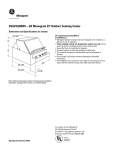
GE Monogram®
Installation
Instructions
24" Outdoor
Cooking Center
Model
ZGG24L
Before you begin— Read these instructions completely and carefully.
IMPORTANT: Save these instructions for local inspector’s use.
IMPORTANT: OBSERVE ALL GOVERNING CODES AND ORDINANCES.
NOTE TO INSTALLER: Be sure to leave these instructions with the Consumer.
NOTE TO CONSUMER: Keep these instructions with your Use and Care Book for future reference.
If you received a damaged cooking center, you should
contact your dealer.
Installation of this cooking center requires basic
mechanical skills. Proper installation is the responsibility
of the installer.
For Monogram local service in your area,
1-800-444-1845.
For Monogram service in Canada, 1-888-880-3030.
For Monogram Parts and Accessories, call
1-800-626-2002.
FOR YOUR SAFETY:
Do not use cooking center in a space where gasoline or
other liquids having flammable vapors are stored or
used.
CAUTION:
• For outdoor use only. Use this cooking center only in
the manner intended by the manufacturer.
• This outdoor cooking gas appliance is not intended to
be installed in or on recreational vehicles and/or
boats.
• Do not use the grill in an explosive atmosphere. Keep
the grill away from areas where gasoline or other
flammable liquids and vapors are stored or being used.
• Observe proper clearances to combustible materials at
all times.
• Do not use a rusty or damaged LP tank.
• Never substitute gases (natural for LP or LP for
natural).
• This grill is factory set for liquid propane gas. A natural
gas conversion kit must be installed before using
natural gas.
• When storing the grill indoors, disconnect the LP tank.
Store the tank outdoors in a well ventilated area.
• Do not store additional LP tanks in or near the gas grill.
• Follow the guidelines on the LP tank for proper storage,
transport and handling.
• Tested in accordance with ANSI Z21.58 latest edition
standard for outdoor cooking gas appliances. This grill
Contents
2
Design Information
Model ................................................................................. 3
Product Dimensions & Clearances .............................. 3
Accessories ...................................................................... 3
Advance Planning ............................................................ 3
Choosing the Location .................................................... 4
Tools & Materials Required ........................................... 4
Step 1: Remove the Packaging ..................................... 4
Step 2: Provide Support,
Installation on a Cart ......................................... 4
In the Commonwealth of Massachusetts:
• This product must be installed by a licensed
plumber or gas fitter.
• When using ball type gas shut off valves, they
shall be T-handle type.
• A flexible gas connector, when used, must not
exceed 3 feet.
IF YOU SMELL GAS:
• Shut off gas to appliance.
• Extinguish any open flame.
• Open lid.
• If odor continues, immediately call your gas supplier.
is for outdoor use only. Check local building codes for
the proper method of installation in the absence of local
codes, this unit should be installed in accordance with
the National Fuel Gas Code No. Z223 latest edition and
the National Electrical Code ANSI/NFPA No. 70-1990.
CALIFORNIA PROPOSITION 65 - WARNING
The burning of gas cooking fuel generates some by
products that are on the list of substances which are
known by the State of California to cause cancer or
reproductive harm. California law requires businesses to
warn customers of potential exposure to such
substances. To minimize exposure to these substances,
always operate this unit according to the use and care
manual, ensuring you provide good ventilation when
cooking with gas.
INSECT WARNING!
Spiders and insects can nest in the burners of this and
any other grill, and cause the gas to flow from the front of
the burner. This is a very dangerous condition which can
cause a fire to occur behind the valve panel, thereby
damaging the grill and making it unsafe to operate.
Inspect the grill twice a year or immediately if any
symptoms appear.
Installation
Step 2: Provide Support,
Built-In Installations .......................................... 5
Step 3: Provide Gas & Electrical Supply ..................... 6
Step 4: Test for Leaks ...................................................... 7
Step 5: Lighting the Grill .................................................. 7
Step 6: Adjusting the Burners ....................................... 8
Finalize Installation .......................................................... 9
Install Rotisserie .............................................................. 9
ZXADYSS, ZXSDBSS, Optional Access Doors ........... 9
ZX24NGB, Natural Gas Conversion Kit ...................... 10
Design Information
24" Outdoor Cooking Center
Model
Product
Dimensions
& Clearances
ZGG24L20 SS
The Monogram 24” Outdoor Cooking Center
is factory set for LP gas and can be converted
to natural gas. Order ZX24NGB Natural gas
conversion kit when natural gas is available.
*12" Min. to Combustibles
4" Min. for Lid Clearance
24-3/4"
12" Clearance to
Combustibles
Both Sides
9"
9"
9"
4-7/8"
9"
24" (Cutout)
18-7/8"
23-3/4"
Manifold
Pipe 3-1/2"
*4" For Lid Clearance when installed
into a non-combustible enclosure.
Allow 12" min. clearance to
combustible vertical surfaces.
Accessories
This grill may be installed on a portable grill
cart or built into an enclosure.
Enclosures can be constructed of non-combustible (masonry) material or of combustible
material such as wood. Insulated jackets are
required for installation into combustible
enclosures.
• ZX24CTBSS, grill cart
• ZX24JBSS, Insulated jacket for a combustible
enclosure.
• ZX24TKBSS is available to conceal the gap
between the cooking center and the
enclosure.
• ZX24CVC, tough vinyl on the outside, felt
lined inside with elastic to hold the cover in
place. Fits grill installed on a cart or when
built-in.
• ZXSDBSS - Stainless Steel Single Access Door
ZXADYSS - Stainless Steel Double Access
Doors – Optional accessories to cover the
access opening under the grill in a built-in
installation.
• ZXLPY, LP gas tank.
Advance
Planning
• This Monogram Outdoor Cooking Center is
designed to be installed on a grill cart or into
an enclosure.
• In a non-combustible (masonry) enclosure,
the grill drops into the opening. A ledge on
each side is required for support.
• An Insulated jacket is available to allow the
grill to be installed in a combustible
enclosure. The insulated jacket must be
supported by a ledge on each side.
• If using a backsplash or rear wall, locate the
electrical service for the rotisserie on the
right side.
• Trim kit ZX24TKBSS is available to conceal
the gap between cooking center and the back
and sides of an enclosure.
Clearances
• Allow 4" at the rear for lid clearance.
• Allow at least 12" clearance at the back of the
grill when exhaust is directed to a window or
a surface that is difficult to clean.
• Allow at least 6" clearance on each side to
any non-combustible material located above
the cooking surface for counterspace. This 6"
clearance will allow for placement and
handling of the rotisserie motor and skewer.
• Allow at least 12" clearance on each side and
12" min. clearance at rear to combustible
vertical materials.
3
Design Information
24" Outdoor Cooking Center
Choosing
the Location
• This cooking center is designed for outdoor
use only. Do not locate the grill in a
building, garage or other enclosed area.
• Ensure that fresh air ventilation is adequate.
• Consider exposure to wind and proximity to
traffic paths.
• The minimum clearances to combustibles
must be maintained at all times.
Tools &
Materials
Required
• Phillips head screwdriver
• Pipe wrench
• Level
• Flat blade screwdriver (3/32" blade)
• Pliers
• Do not install a grill below overhead
unprotected combustible construction.
• The installation must conform to local codes
or in the absence of local codes, with the
national fuel gas code, ANSI Z223 latest
edition.
CAUTION This Cooking Center
is extremely heavy. 2 people are required
for lifting and placing the product onto a
cart or into an enclosure.
(Not supplied)
PRUDENCE Ce centre de cuisson
est extrêmement lourd. Il faut deux
personnes pour le soulever et le mettre sur
un chariot ou dans une enceinte.
Step 1
Remove the
Packaging
• Open the box and remove packaging.
• Open the grill lid and remove hardware
accessory carton. Check contents.
2 Grill Grates
Motor
Spit Forks
2 Ceramic Briquette Trays
Rotisserie Rod and Handle
LP Regulator
Step 2
Provide
Support
Installation
On a Cart
4
The Outdoor Cooking Center can be installed
on a ZX24CTBSS cart which is designed
specifically for this model. Follow the installation instructions provided with the cart to
install. Proceed to Gas supply, Step 3, to
complete the installation.
Type 1 Acme,
20 Lb. LP Tank with Overfill
Protection Device. (not supplied)
Order ZXLPY
Required for Grill Cart Installation
• Allow at least 12" clearance at the back of the
grill when exhaust is directed to a window or
a surface that is difficult to clean.
Installation
24" Outdoor Cooking Center
Built-In
Installations
• This grill may be installed into a combustible
or non-combustible enclosure.
• Combustible enclosures require the use of an
insulated jacket.
Clearances
• Allow 4" at the rear for lid clearance.
• Allow at least 6" clearance on each side to
any non-combustible material located above
the cooking surface for counterspace. The 6"
clearance allows for placing and handling
the rotisserie motor and skewer.
• Allow at least 12" clearance on each side and
rear to combustible vertical materials.
Built-In
Installations
Back
Acorn Nut
ZX24TKBSS Trim Kit
This kit is available for non-combustible
enclosures. The trim will conceal the gap at
the rear and both sides of the opening.
• Secure trim to the sides and back with screws
provided.
• Place the grill into the enclosure.
4" Min. for Lid
Clearance
24-1/2"
19"
35-1/2
Max."
Gas Inlet
18-1/4"
Opening for
Double Access
Doors
If Installing
an Electrical
Outlet for
the Rotisserie
Motor, Mount
on Right Side
(6.5 AMP Min.)
Right Side
ZX24JBSS Insulated Jacket
The insulated jacket is required for combustible enclosures.
• Install left and right side pieces with bolts
provided.
• Secure bolts inside the grill with acorn nuts.
• Install back panel to side panels. Place the
grill into the enclosure.
12" Min. to
Combustibles
4" Min. for Lid
25-3/4"
19-1/2"
35-1/2
Max."
If Installing an
Electrical Outlet
for the Rotisserie
Motor, Mount on
Right Side
(6.5 AMP Min.)
Gas Inlet
8"
24-1/8"
Installation in a non-combustible enclosure.
• In a non-combustible (masonry) enclosure,
the grill drops into the opening. A ledge on
each side is required for support.
18-1/4"
Opening for
Double Access
Doors
8"
24-1/8"
Installation in a combustible enclosure,
ZX24JBSS insulated jacket is required
• Combustible enclosures require ZX24JBSS
insulated jacket. The insulated jacket must
be supported by a ledge on each side.
• Construct the enclosure as shown. Install the
insulated jacket onto the grill. Place the
cooking center into the opening. No
installation hardware is required.
5
Installation
24" Outdoor Cooking Center
Step 3
Provide
Gas &
Electrical
Supply
NOTE: Skip this step if you wish to connect to
natural gas supply. Order ZX24NGB kit. Refer to
Natural Gas Conversion Instructions, page 10.
WARNING
PRODUCT STORAGE
When storing LP models indoors, disconnect the LP tank. Store the tank outdoors
in a well ventilated area.
Do not store spare LP tanks in or near the
Outdoor Cooking Center enclosure.
RANGEMENT DU
PRODUIT
Lors du rangement des modèles à gas à
l’intérieur, il faut débrancher la bouteille
de gaz. Il faut remiser la bouteille de gaz à
l’extérieur, dans un endroit bien ventilé.
Il ne faut par remiser les bouteilles de gaz à
proximité de l’enceinte du centre de
cuisson en plein air.
LP Hose
Pre-Attached
Inlet
Coupler Sleeve
Main Valve
L.P. Regulator
ATTENTION
• Connect the regulator to the quick
disconnect hose assembly.
• Check to be sure the main valve on the LP
tank is completely closed.
To connect the tank:
• Insert the coupler sleeve over the tank inlet,
turn clockwise to tighten.
To disconnect the tank:
• Turn off the main tank valve.
• Grasp the coupler sleeve and turn counterclockwise. Remove the inlet from the
opening.
ELECTRICAL SUPPLY
The rotisserie requires 120V, 60Hz., and
connected to an individual properly
grounded branch circuit protected by a 15
amp circuit breaker or time delay fuse.
The power cord on the rotisserie is equipped
with a three-prong (grounding plug which
mates with a standard three-prong grounding
wall receptacle to minimize the possibility of
shock hazard from this appliance.
If the electrical service provided does not
meet the above specifications, it is recommended that a licensed electrician install an
approved outlet.
6
L.P. Tank
LP operating pressure is 10" W.C.
IMPORTANT: The LP tank must be a Type 1
Acme. Do not attempt to change or alter these
supplied parts Do not attempt to use the
regulator/hose assembly with a standard 510
POL tank/valve assembly.
DO NOT UNDER ANY CIRCUMSTANCES,
CUT OR REMOVE THE THIRD (GROUND)
PRONG FROM THE POWER CORD.
• For built-in grill installations, locate the
electrical outlet on the right hand side.
Installation
24" Outdoor Cooking Center
Step 4
Test for
Leaks
WARNING TEST FOR LEAKS
A complete gas tightness check must be
performed at the installation site.
V´ERIFICATION
DES FUITES
Il faut vérifier que l’installation n’a aucune
fuite de gaz.
ATTENTION
• Do not use the grill until all connections
have been leak tested.
• Repeat leak test after each LP tank change.
• Check to be sure the main valve on the LP
tank or the shut-off valve is in the “OFF”
position.
• Make a soap solution of one part liquid
detergent and one part water.
The valve panel must be removed to check the
valves and fittings.
• All control valves should be in the “OFF”
position.
• Remove the knobs.
• Remove the 4 screws holding the valve panel
to the grill (2 behind burner knobs and two
below valve panel).
• Pull the panel outwards and unplug the wires
from the back of the rotary igniters.
Step 5
Lighting
the Grill
WARNING
Do not attempt to
light the grill if the odor of gas is present.
ATTENTION Il ne faut pas essayer
d’allumer le gril s’il y a une odeur de gaz.
CAUTION
Keep hands and face
as far away from the grill as possible when
lighting.
4 Valve Panel
Attachment Screws
Igniter
Wires
TO TEST:
• Apply the soap solution around the
connections, valve and tubing.
• Turn the gas supply on.
• Check all connections from the supply line
or LP tank up to and including the manifold
pipe assembly.
• If a leak is detected, turn gas supply to off
and tighten fittings. Turn the gas on and
check again.
NOTE: The spark will produce a snapping
sound. This is normal.
• If the burner does not light within 4
seconds, turn knobs to “OFF” and wait 5
minutes for the gas to dissipate before trying
again.
• If the burner does not light after several
attempts, the burner can be lit with a match.
TO MATCH LIGHT:
• Strike a match and hold over the match light
hole at the top left side. See illustration.
• Push and turn the control knob to “LITE”.
PRUDENCE Pendant l’allumage,
il faut maintenir les mains et le visage aussi
loin que possible du gril.
• Open the lid.
• Turn all knobs to “OFF” position.
• Turn gas supply on at the LP tank or shut-off
valve.
NOTE: When lighting the burner for the first
time or after a LP tank change, allow up to 20
seconds to purge air from the lines.
• Push and turn control knob to “LITE”
position, immediately turn the rotary igniter
knob next to the burner knob.
Match
Light
Hole
WAIT 5 MINUTES BEFORE RELIGHTING A
HOT GRILL.
7
Installation
24" Outdoor Cooking Center
Step 6
Adjusting
the Burners
Adjustments should not be required, unless
vibration during transit or variations in local
gas supply make minor adjustments necessary.
Adjustments must be made by a qualified
technician at the time of installation. Extreme
care should be used if adjustments are made
after installation.
Grill Box
• Turn gas supply on.
• Push and turn the burner control knobs to
the “LITE” position. Up to 20 seconds may be
required to to purge air from the lines.
Air Shutter
• Flames should be blue and stable with no
Lock Screw
yellow tips, excessive noise or lifting from the
burner. If any of these conditions exist turn
control to off and check air shutter and
• Locate and loosen the lock screw on the
burner ports for debris or spider webs.
face of the air shutter with a screwdriver.
•
Turn burner to the “LITE” position.
1-1/2"
• If the flame is yellow, indicating insufficient
air, open the air shutter to allow more air to
the burner.
• If the flame is noisy and tends to lift away
3/8"
from the burner, there is too much air. Turn
the air shutter to reduce the opening.
• Once adjusted, turn the burner off and
TO ADJUST:
reverse steps to re-install the valve panel
• The valve panel cover must be removed to
cover.
access the the air shutter. Follow the
instructions in Step 4, Test for Leaks.
Low setting Adjustment:
Minor adjustments may be required due to
fluctuations in local gas pressure. Adjustments
to increase or decrease gas flow may be
necessary.
• Turn burner knob to “LITE” position.
• Turn the control knob to the lowest setting,
all the way counter-clockwise.
• Remove the knob by pulling straight out.
• Insert a thin-blade flat screwdriver into the
valve shaft and hold. (3/32" blade width
recommended.)
• Grip the shaft with pliers and turn counterclockwise to lower the flame, or clockwise to
increase the flame.
WARNING Always check the low
flame size for stability. A burner flame
which is too small may go out or be extinguished easily. This can cause unburned
gas to escape and cause a hazardous
condition.
8
• When the desired setting
is made, replace the
knob and turn burner
off.
Valve Stem
ATTENTION Il faut toujours
vérifier la stabilité de la flamme au ralenti.
Une flamme trop petite peut s’éteindre
facilement. Ceci cause l’émission de gaz
non brûlé, ce qui est dangereux.
Installation
24" Outdoor Cooking Center
Finalize
Installation
• Place the small ceramic briquette tray at the
rear and larger tray towards the front.
• Place the grill grates over the opening.
Note: The ceramic briquettes may move during shipping or when
repositioning for rotisserie use. For best cooking performance,
slide briquettes on the tray so they are evenly spaced and do not
block vent holes.
Install
Rotisserie
• Remove burner grates.
• Remove front (large) ceramic briquette tray.
• Place small ceramic briquette tray in the rear
slots as shown.
• Place drip pan on the grill floor and against
the briquette tray.
• Slide the motor down into the channel on
the right side.
• To use, place pointed end of the skewer into
the motor, and the threaded end resting on
the left side support.
• Screw handle onto the threaded end of the
skewer.
Note: Remove motor when not in use. Store motor in dry place.
Install
Optional
Access Doors
ZXADYSS
and
ZXSDBSS
(For Built-In
Installations
Only)
ZXADYSS - Double Doors
The opening should be 24-1/8" wide and
18-1/4" high.
• Place the frame into the opening and secure
with screws on all sides.
• Hang the doors on the hinges as shown.
ZXSDBSS - Single Doors
The opening should be 22" wide and 20" high.
9
ZX24NGB
Natural Gas Conversion Kit
Parts supplied:
• Natural gas regulator
• Natural gas orifices
• Adapter 1/2" to 3/8" flare fitting
• Two, 1/2" NPT close nipple
Materials Required:
(not supplied)
• 12 ft. to 15 ft. max. flexible hose with 3/8"
flare end (corrugated stainless steel
preferred).
• Pipe wrench
• Pipe threading compound
• Manual gas shut-off valve
• Appropriate length of gas line to reach the
permanent installation location with a 3/8"
flare end.
• Flat blade screwdriver
Note: Optional ZX144HKY quick disconnect hose for natural gas is
available to reach a 144" connection.
The grill and its individual shut-off valve must
be disconnected from the gas supply during
any pressure testing of the system at test
pressures in excess of 1/2 PSIG.
The grill must be isolated from the gas supply
system by closing its individual shut-off valve
during any pressure testing of the system at
test pressures equal to or less than 1/2 PSIG.
The installation of this grill must conform
with local codes or, in the absence of local
codes, with the National fuel gas code, ANSI
Z223 latest edition. Installation in Canada
must be in accordance with the Standard CAN
1-b149-1 and/or .2 (installation code for gas
burning appliances and equipment) and local
codes.
Operating pressure is 4" W.C.
Supply pressure should be 5" to 14" W.C. If
pressure is more than 14" W.C. a step down
regulator is required.
Step 1
Install
Fittings &
Regulator
10
Check with local gas utility or with local codes
for instructions on installing gas supply lines.
Be sure to check on type and size of run and
how deep to bury the line. If the gas line is too
small, the grill will not function properly.
• Install a manual gas shut-off valve in an easily
accessible location.
• Use threading compound on non-flare
fittings only. Do not use threading compound
on the male end of the 1/2 NPT to 3/8 flare
adapter.
• Make connections as shown.
• Remove quick disconnect hose assembly from
manifold pipe.
• Leave flare fitting in the manifold pipe (1/2"
to 3/8" flare).
• Attach installer supplied gas line to end of
flare fitting on the manifold.
• Install regulator to gas line.
• Install 1/2" NPT close nipple to supplier
installed shut-off valve.
• Check to be sure the regulator arrow points
in the direction of gas flow, towards the grill
and away from the gas supply.
Installer
Supplied
TUBING
(3/8" FLARE)
Adapter 1/2 NPT
to 3/8" Flare Fitting
1/2 NPT Close Nipple
Natural Gas 4.0" Regulator
1/2 NPT Close Nipple
Installer Supplied
Shut-Off
Natural Gas Supply
ZX24NGB
Natural Gas Conversion Kit
Step 2
Install
Orifices
Step 3
Test for
Leaks
• Open the lid.
• Remove racks and briquette trays.
• Remove tie-downs on burners.
• Remove burner knobs and 4 screws on the
valve panel (2 screws behind knobs and
2 screws below valve panel).
• Lift the control panel up and and tilt back
away from the grill.
• Disconnect 2 ignitor wires.
• Remove control panel.
• Pull burners back and away from the orifices.
• Remove original orifices, one on each side.
• Apply threading compound to new orifices,
install and tighten.
• Re-position burner inside the grill and with
air shutter ends covering the orifices.
• Check air shutter, the shutter should be
open approximately 5/16”.
WARNING
TEST FOR LEAKS
A complete gas tightness check must be
performed at the installation site.
V´ERIFICATION
DES FUITES
Il faut vérifier que l’installation n’a aucune
fuite de gaz.
ATTENTION
• Do not use the grill until all connections
have been leak tested.
Step 4
Adjust the
Burners
• Turn gas suply on.
• Flames should be blue and stable with some
yellow tips and no excessive noise or lifting
from the burner. If any of these conditions
exist, check air shutter and burner ports for
debris or spider webs.
To Adjust:
• If the flame is yellow, indicating insufficient
air, open the air shutter to allow more air to
the burner.
• If the flame is noisy and tends to lift away
from the burner, there is too much air. Turn
the air shutter to reduce the opening.
1-1/2"
Grill Box
Orifice
• Check to be sure that the shut-off valve is in
the “OFF” position.
• In a spray bottle, make a soap solution of
one part liquid detergent and one part water.
TO TEST:
• Spray the soap solution around the
connections, valve and tubing.
• Turn the gas supply on.
• Check all connections from the gas supply
line up to and including the manifold.
• If a leak is detected, turn gas supply off and
tighten fittings. Turn the gas on and check
again.
Grill Box
Air Shutter
Lock Screw
3/8"
11
Note: While performing installations described in this book,
safety glasses or goggles should be worn.
For Monogram® local service in your area, call
1-800-444-1845.
Note: Product improvement is a continuing endeavor at
General Electric. Therefore, materials, appearance and
specifications are subject to change without notice.
Monogram.
®
We bring good things to life.
Pub. No. 49-8966-2
Dwg. No. 164D3333P193
Printed in USA
(N.D. 728) 3/03
10905-Rev. 2
GE Consumer Products
General Electric Company
Louisville, KY 40225
© 2003 General Electric Company