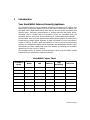
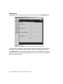
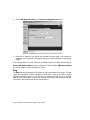
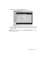
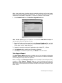
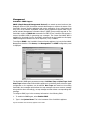
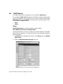
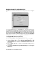
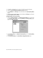
1
SONICWALL
Internet Security Appliances
SonicWALL, Inc.
1160 Bordeaux Drive
Sunnyvale, CA 94089-1209
Tel: (408) 745-9600
Fax: (408) 745-9300
E-mail: [email protected]
Web: www.sonicwall.com
Part# 232-000091-01
Rev. B 10/00
Contents
Copyright Notice ............................................................................ 5
About this Guide ............................................................................ 7
SonicWALL Technical Support ......................................................... 8
1 Introduction
Your SonicWALL Internet Security Appliance ................................... 9
SonicWALL Internet Security Appliance Functional Diagram .............10
SonicWALL Internet Security Appliance Features .............................11
2 SonicWALL Installation
Inspecting the Package .................................................................15
Overview .....................................................................................15
Connecting the SonicWALL to the Network .....................................16
Performing the Initial Configuration ...............................................18
3 Managing Your SonicWALL
Log into the SonicWALL using a Web Browser ................................28
Status ..........................................................................................29
CLI Support and Remote Management ...........................................30
4 General and Network Settings
Network .......................................................................................32
Network Settings ..........................................................................33
Standard Configuration .................................................................35
NAT with DHCP Client Configuration ..............................................37
NAT with PPPoE Configuration .......................................................39
Setting the Time and Date ............................................................41
Setting the Administrator Password ...............................................42
Setting the Administrator Inactivity Timeout ...................................43
5 Logging and Alerts
View Log .....................................................................................44
SonicWALL Log Messages .............................................................45
Log Settings .................................................................................46
Log Categories .............................................................................48
Alert Categories ............................................................................49
Reports ........................................................................................49
6 Content Filtering and Blocking
Categories ...................................................................................51
Time of Day .................................................................................53
List Update ..................................................................................53
Contents Page 1
Customize ....................................................................................55
Keywords .....................................................................................57
Consent .......................................................................................57
7 Web Management Tools
Restarting the SonicWALL .............................................................61
Preferences ..................................................................................62
Exporting the Settings File ............................................................63
Importing the Settings File ............................................................64
Restoring Factory Default Settings .................................................65
Upgrade Features .........................................................................68
Diagnostic Tools ...........................................................................69
DNS Name Lookup .......................................................................69
Ping ............................................................................................70
Packet Trace ................................................................................72
Tech Support Report ....................................................................73
8 Network Access Rules
Services .......................................................................................75
Windows Networking (NetBIOS) Broadcast Pass Through ................76
Detection Prevention ....................................................................76
Network Connection Inactivity Timeout ..........................................77
Add Service ..................................................................................77
Rules ...........................................................................................78
Understanding the Access Rule Hierarchy .......................................84
SonicWALL TELE2 and SOHO2 IP Address Management ..................87
Users ...........................................................................................88
Management ...............................................................................90
Management Method ....................................................................91
9 Advanced Features
Proxy Relay ..................................................................................94
Intranet .......................................................................................96
Routes .........................................................................................98
DMZ Addresses (SonicWALL XPRS2, PRO, and PRO-VX Only) ...........99
Delete a DMZ Address Range ...................................................... 101
One-to-One NAT ........................................................................ 101
The Ethernet Tab ....................................................................... 104
10 DHCP Server
Setup ........................................................................................ 106
Enable DHCP Server ................................................................... 107
Page 2 SonicWALL Internet Security Appliance User’s Guide
Deleting Dynamic Ranges and Static Entries ................................. 108
DHCP Status .............................................................................. 108
SonicWALL TELE2 and SOHO2 IP Address Management ................ 109
11 SonicWALL VPN
VPN Applications ........................................................................ 111
The VPN Interface ...................................................................... 112
SonicWALL VPN Client for Remote Access and Management .......... 113
The Configure Tab ...................................................................... 114
VPN Advanced Settings ............................................................... 115
Advanced Settings for VPN Configurations .................................... 117
Enabling Group VPN on the SonicWALL ........................................ 118
Group VPN Client Configuration ................................................... 120
Manual Key Configuration between the SonicWALL and VPN Client . 123
Installing the VPN Client Software ................................................125
VPN between Two SonicWALLs .................................................... 130
Example of Manual Key Configuration between Two SonicWALLs ... 133
IKE Configuration between Two SonicWALLs ................................ 136
Example: Linking Two SonicWALLs .............................................. 139
Testing a VPN Tunnel Connection Using PING .............................. 142
Configuring Windows Networking ................................................143
Adding, Modifying and Deleting Destination Networks ................... 146
RADIUS and XAUTH Authentication .............................................. 147
SonicWALL Enhanced VPN Logging .............................................. 149
Disabling Security Associations .................................................... 150
Basic VPN Terms and Concepts ................................................... 151
12 SonicWALL Options and Upgrades
SonicWALL VPN Upgrade ............................................................ 154
SonicWALL VPN Client for Windows ............................................. 154
SonicWALL Network Anti-Virus .................................................... 155
Content Filter List Subscription .................................................... 155
SonicWALL High Availability Upgrade ........................................... 155
Vulnerability Scanning Service ..................................................... 156
SonicWALL Authentication Service ............................................... 156
SonicWALL ViewPoint Reporting .................................................. 156
SonicWALL Per Incident Support .................................................. 157
SonicWALL Premium Support ...................................................... 157
SonicWALL Extended Warranty .................................................... 157
SonicWALL Global Management System ....................................... 157
Contents Page 3
13 Hardware Description
SonicWALL PRO and PRO-VX Front Panel ..................................... 158
SonicWALL PRO and PRO-VX Back Panel ...................................... 159
SonicWALL XPRS2 Front Panel ..................................................... 160
SonicWALL XPRS2 Front Panel Description ................................... 160
SonicWALL XPRS2 Back Panel ..................................................... 161
The SonicWALL XPRS2 Back Panel Description .............................. 161
SonicWALL SOHO2 and TELE2 Front Panel ................................... 162
SonicWALL SOHO2 and SonicWALL TELE2 Front Panel Description . 162
SonicWALL SOHO2 and TELE2 Back Panel .................................... 163
The SonicWALL SOHO2 and TELE2 Back Panel Description ............ 163
14 Troubleshooting Guide
The Link LED is off. .................................................................... 165
A computer on the LAN cannot access the Internet. ...................... 165
The SonicWALL does not establish authenticated sessions. ............ 165
The SonicWALL does not save changes that you have made. ......... 166
Duplicate IP address errors occur when the SonicWALL is installed 166
Machines on the WAN are not reachable. ..................................... 166
15 Appendices
Appendix A - Technical Specifications ........................................... 167
Appendix B - Introduction to Networking ...................................... 170
Overview ................................................................................... 170
Network Hardware Components .................................................. 170
Network Types ........................................................................... 170
Firewalls .................................................................................... 170
Gateways ................................................................................... 171
Network Protocols ...................................................................... 171
IP Addressing ............................................................................. 172
Appendix C - IP Port Numbers ..................................................... 175
Appendix D - Configuring TCP/IP Settings .................................... 176
Appendix E - Erasing the Firmware .............................................. 178
Appendix F - Securing the SonicWALL .......................................... 180
Mounting the SonicWALL PRO and SonicWALL PRO-VX ................. 180
Appendix G - Electromagnetic Compatibility .................................. 181
SonicWALL PRO and SonicWALL PRO-VX ...................................... 181
SonicWALL XPRS2, SonicWALL SOHO2 and SonicWALL TELE2 ....... 182
Notes ........................................................................................ 183
Page 4 SonicWALL Internet Security Appliance User’s Guide
Copyright Notice
©
2001 SonicWALL, Inc. All rights reserved.
Under the copyright laws, this manual or the software described within, can not be copied,
in whole or part, without the written consent of the manufacturer, except in the normal use
of the software to make a backup copy. The same proprietary and copyright notices must
be affixed to any permitted copies as were affixed to the original. This exception does not
allow copies to be made for others, whether or not sold, but all of the material purchased
(with all backup copies) can be sold, given, or loaned to another person. Under the law,
copying includes translating into another language or format.
SonicWALL is a registered trademark of SonicWALL, Inc.
Other product and company names mentioned herein can be trademarks and/or registered
trademarks of their respective companies.
Specifications and descriptions subject to change without notice.
LIMITED WARRANTY
SonicWALL, Inc. warrants the SonicWALL Internet Security Appliance (the Product) for one
(1) year from the date of purchase against defects in materials and workmanship. If there
is a defect in the hardware, SonicWALL will replace the product at no charge, provided that
it is returned to SonicWALL with transportation charges prepaid. A Return Materials
Authorization (RMA) number must be displayed on the outside of the package for the
product being returned for replacement or the product will be refused. The RMA number
can be obtained by calling SonicWALL Customer Service between the hours of 8:30 AM and
5:30 PM Pacific Standard Time, Monday through Friday.
Phone:(408) 752-7819
Fax:(408) 745-9300
Web: <http://www.sonicwall.com/support>
This warranty does not apply if the Product has been damaged by accident, abuse, misuse,
or misapplication or has been modified without the written permission of SonicWALL.
In no event shall SonicWALL, Inc. or its suppliers be liable for any damages whatsoever
(including, without limitation, damages for loss of profits, business interruption, loss of
information, or other pecuniary loss) arising out of the use of or inability to use the Product.
Some states do not allow the exclusion or limitation of implied warranties or liability for
incidental or consequential damages, so the above limitation or exclusion can not apply to
you. Where liability can not be limited under applicable law, the SonicWALL liability shall
be limited to the amount you paid for the Product. This warranty gives you specific legal
rights, and you can have other rights which vary from state to state.
By using this Product, you agree to these limitations of liability.
Preface Page 5
THIS WARRANTY AND THE REMEDIES SET FORTH ABOVE ARE EXCLUSIVE AND
IN LIEU OF ALL OTHER WARRANTIES, ORAL OR WRITTEN, EXPRESS OR
IMPLIED.
No dealer, agent, or employee of SonicWALL is authorized to make any extension or
addition to this warranty.
Page 6 SonicWALL Internet Security Appliance User’s Guide
About this Guide
Thank you for purchasing the SonicWALL Internet Security Appliance. The SonicWALL
protects your Local Area Network (LAN) from attacks and intrusions, filters objectional Web
sites, provides private VPN connections to business partners and remote offices, and offers
a centrally-managed defense against software viruses.
This guide covers the installation and configuration of the SonicWALL SOHO2, SonicWALL
TELE2, SonicWALL XPRS2, SonicWALL PRO and SonicWALL PRO-VX. The instructions are
the same for every hardware model except where specifically noted.
Organization of This Guide
Chapter 1, Introduction, describes the features and applications of the SonicWALL.
Chapter 2, SonicWALL QuickStart Installation, demonstrates how to connect the
SonicWALL to your network and perform the initial configuration.
Chapter 3, Managing Your SonicWALL, provides a brief overview of the SonicWALL Web
Management Interface.
Chapter 4, Network Settings, describes the configuration of the SonicWALL IP settings,
time and password.
Chapter 5, Logging and Alerting, illustrates the SonicWALL logging, alerting and
reporting features.
Chapter 6, Content Filtering and Blocking, describes SonicWALL Web content filtering,
including subscription updates and customized Web blocking.
Chapter 7, Web Management Tools, provides directions to restart the SonicWALL,
import and export settings, upload new firmware, and perform diagnostic tests.
Chapter 8, Network Access Rules, explains how to permit and block traffic through the
SonicWALL, set up servers, and enable remote management.
Chapter 9, Advanced Features, describes advanced SonicWALL settings, such as One-toOne NAT, Automatic Web Proxying and DMZ addresses.
Chapter 10, DHCP Server, describes the configuration and setup of the SonicWALL DHCP
server.
Chapter 11, SonicWALL VPN, explains how to create a VPN tunnel between two
SonicWALLs and from the VPN client to the SonicWALL.
Chapter 12, SonicWALL Options and Upgrades, presents a brief summary of the
SonicWALL's subscription services, firmware upgrades and other options.
Chapter 13, Hardware Description, illustrates and describes the SonicWALL front and
back panel displays. This chapter is divided into three sections for the SonicWALL SOHO2
and SonicWALL TELE2, the SonicWALL XPRS2, and the SonicWALL PRO and SonicWALL
PRO-VX.
Preface Page 7
Chapter 14, Troubleshooting Guide, shows solutions to commonly encountered
problems.
Appendix A, Technical Specifications, lists the SonicWALL specifications.
Appendix B, Introduction to Networking, provides an overview of the Internet, TCP/IP
settings, IP security, and other general networking topics.
Appendix C, IP Port Numbers, offers information about IP port numbering.
Appendix D, Configuring TCP/IP Settings, provides instructions for configuring your
Management Station's IP address.
Appendix E, Erasing the Firmware, describes the firmware erase procedure.
Appendix F, Securing the SonicWALL, details the steps necessary to safely mount the
SonicWALL on a mounting rack.
Appendix G, Electromagnetic Compatibility, presents important emissions standards
approvals and EMC information.
SonicWALL Technical Support
For fast resolution of technical questions, please visit the SonicWALL Tech Support Web
site at <http://www.sonicwall.com/support>. There, you will find resources to resolve
most technical issues and a Web request form to contact one of the SonicWALL Technical
Support engineers.
Page 8 SonicWALL Internet Security Appliance User’s Guide
1
Introduction
Your SonicWALL Internet Security Appliance
The SonicWALL Internet security appliance provides a complete security solution that
protects your network from attacks, intrusions, and malicious tampering. In addition, the
SonicWALL filters objectionable Web content and logs security threats. SonicWALL VPN
provides secure, encrypted communications to business partners and branch offices.
SonicWALL VPN is included with the SonicWALL TELE2, the SonicWALL PRO, the
SonicWALL PRO-VX, and the GX series of appliances. It is also available as an upgrade.
The SonicWALL Internet security appliance uses stateful packet inspection to ensure secure
firewall filtering. Stateful packet inspection is widely considered to be the most effective
method of filtering IP traffic. MD5 authentication is used to encrypt communications
between your Management Station and the SonicWALL Web Management Interface. MD5
Authentication prevents unauthorized users from detecting and stealing the SonicWALL
password as it is sent over your network.
The SonicWALL family of Internet security appliances include eight SonicWALL models
customized to the requirements of different networks.
SonicWALL Feature Chart
SonicWALL
Model
Nodes
VPN
DMZ Port
High
Availability
Anti-Virus
TELE2
5
Included
SOHO2/10
10
Optional
SOHO2/50
50
Optional
XPRS2
Unlimited
Optional
Included
PRO
Unlimited
Included
Included
Optional
Optional
PRO-VX
Unlimited
Included
Included
Included
Optional
GX250
Unlimited
Included
Included
Included
Optional
GX650
Unlimited
Included
Included
Included
Optional
Introduction Page 9
SonicWALL Internet Security Appliance Functional Diagram
The following figure illustrates the SonicWALL's security functions.
By default, the SonicWALL allows outbound access from the LAN to the Internet and blocks
inbound access from the Internet to the LAN. Users on the Internet are restricted from
accessing resources on the LAN unless they are authorized remote users or Network Access
Rules were created to allow inbound access.
If the SonicWALL includes a DMZ port, users on the LAN and on the Internet have full
access to the devices on the DMZ.
Page 10 SonicWALL Internet Security Appliance User’s Guide
SonicWALL Internet Security Appliance Features
Internet Security
•
ICSA-Certified Firewall
After undergoing a rigorous suite of tests to expose security vulnerabilities, SonicWALL
Internet security appliances have received Firewall Certification from ICSA, the
internationally-accepted authority on network security. The SonicWALL uses stateful
packet inspection, the most effective method of packet filtering, to protect your LAN
from hackers and vandals on the Internet.
•
Hacker Attack Prevention
The SonicWALL automatically detects and thwarts Denial of Service (DoS) attacks such
as Ping of Death, SYN Flood, LAND Attack, and IP Spoofing.
•
Network Address Translation (NAT)
Network Address Translation (NAT) translates the IP addresses used on your private
LAN to a single, public IP address that is used on the Internet. NAT allows multiple
computers to access the Internet, even if only one IP address has been provided by
your ISP.
•
Network Access Rules
The default Network Access Rules allow traffic from the LAN to the Internet and block
traffic from the Internet to the LAN. You can create additional Network Access Rules
that allow inbound traffic to network servers, such as Web and mail servers, or that
restrict outbound traffic to certain destinations on the Internet.
•
AutoUpdate
The SonicWALL maintains the highest level of security by automatically notifying you
when new firmware is released. When new firmware is available, the SonicWALL Web
Management Interface displays a link to download and install the latest firmware. The
SonicWALL also sends an e-mail with firmware release notes.
•
DMZ Port
SonicWALL XPRS2, SonicWALL PRO and SonicWALL PRO-VX include a DMZ port
allowing users to access public servers, such as Web and FTP servers. While Internet
users have unlimited access to the DMZ, the servers located on the DMZ are still
protected against DoS attacks.
•
SNMP Support
SNMP (Simple Network Management Protocol) is a network protocol used over
User Datagram Protocol (UDP) that allows network administrators to monitor the status
of the SonicWALL Internet Security appliances and receive notification of any critical
events as they occur on the network.
Introduction Page 11
Content Filtering
•
SonicWALL Content Filtering Overview
You can use the SonicWALL Web content filtering to enforce your company's Internet
access policies. The SonicWALL blocks specified categories, such as violence or nudity,
using an optional Content Filter List. Users on your network can bypass the Content
Filter List by authenticating with a unique user name and password.
•
Content Filter List Updates (optional)
Since content on the Internet is constantly changing, the SonicWALL automatically
updates the optional Content Filter List every week to ensure that access restrictions
to new and relocated websites and newsgroups are properly enforced.
•
Log and Block or Log Only
You can configure the SonicWALL to log and block access to objectional Web sites, or
to log inappropriate usage without blocking Web access.
•
Filter Protocols
In addition to filtering access to Web sites, the SonicWALL can also block Newsgroups,
ActiveX, Java, Cookies, and Web Proxies.
Logging and Reporting
•
Log Categories
You can select the information you wish to display in the SonicWALL event log. You can
view the event log from the SonicWALL Web Management Interface or receive the log
as an e-mail file.
•
Syslog Server Support
In addition to the standard screen log, the SonicWALL can write extremely detailed
event log information to an external Syslog server. Syslog is the industry-standard
method to capture information about network activity.
•
ViewPoint Reporting
Monitoring critical network events and activity, such as security threats, inappropriate
Web use, and bandwidth levels, is an essential component of network security.
SonicWALL ViewPoint compliments the SonicWALL security features by providing
detailed and comprehensive reports of network activity.
SonicWALL ViewPoint is a software application that creates dynamic, Web-based
network reports. ViewPoint reporting generates both real-time and historical reports to
offer a complete view of all activity through your SonicWALL Internet security
appliance.
•
E-mail Alerts
The SonicWALL can be configured to send alerts of high-priority events, such as
attacks, system errors, and blocked Web sites. When these events occur, alerts can be
immediately sent to an e-mail address or e-mail pager.
Dynamic Host Configuration Protocol (DHCP)
Page 12 SonicWALL Internet Security Appliance User’s Guide
•
DHCP Server
The DHCP Server offers centralized management of TCP/IP client configurations,
including IP addresses, gateway addresses, and DNS addresses. Upon startup, each
network client receives its TCP/IP settings automatically from the SonicWALL DHCP
Server.
•
DHCP Client
DHCP Client allows the SonicWALL to acquire TCP/IP settings (such as IP address,
gateway address, DNS address) from your ISP. This is necessary if your ISP assigns you
a dynamic IP address.
Installation and Configuration
•
Installation Wizard
The SonicWALL Installation Wizard helps quickly install and configure the SonicWALL.
•
Online help
SonicWALL help documentation is built into the SonicWALL Web Management Interface
for easy access during installation and management.
IPSec VPN
•
SonicWALL VPN
SonicWALL VPN provides a simple, secure tool that enables corporate offices and
business partners to connect securely over the Internet. By encrypting data,
SonicWALL VPN provides private communications between two or more sites without
the expense of leased site-to-site lines. SonicWALL VPN comes standard with the
SonicWALL TELE2, the SonicWALL PRO and the SonicWALL PRO-VX, and can also be
purchased as an upgrade.
•
VPN Client Software for Windows
Mobile users with dial-up Internet accounts can securely access remote network
resources with the SonicWALL VPN Client. The SonicWALL VPN Client establishes a
private, encrypted VPN tunnel to the SonicWALL, allowing users to transparently access
network servers from any location. The SonicWALL PRO includes a single VPN client for
secure remote management. The SonicWALL PRO-VX includes 50 VPN client licenses
for remote management and remote access. Single, 10, 50 and 100 VPN client license
packs can be purchased separately.
Introduction Page 13
Contact SonicWALL, Inc. for information about the Content Filter List, Network AntiVirus subscriptions, and other upgrades.
Web:
E-mail:
Phone:
Fax:
http://www.sonicwall.com
[email protected]
(408) 745-9600
(408) 745-9300
Page 14 SonicWALL Internet Security Appliance User’s Guide
2
SonicWALL Installation
This chapter describes the procedure used to install your SonicWALL and perform the initial
configuration.
Inspecting the Package
The following items should be included in the package:
•
One SonicWALL Internet security appliance
•
One power supply (not included with International SonicWALL PRO or PRO-VX)
•
One Category 5 Ethernet crossover cable (labeled "Crossover")
•
One Category 5 Ethernet standard cable
•
One SonicWALL Quickstart Guide
•
One Companion CD
•
One SonicWALL Internet Security Appliance User's Guide
If an item is missing from the package, you can contact SonicWALL, Inc. by phone at
(408) 752-7819 or submit a Web Support Form at <http://techsupport.sonicwall.com/
swtech.html>.
Overview
Here are a few helpful guidelines for installing the SonicWALL appliance.
•
The WAN Ethernet port should be connected to the Internet router or modem.
•
The LAN Ethernet port should be connected to a network hub or switch on the internal,
protected network.
•
The DMZ Ethernet port, included with the SonicWALL XPRS2, the SonicWALL PRO and
the SonicWALL PRO-VX, should be connected to publicly accessible servers, such as
Web and Mail servers.
•
A crossover cable should be used when connecting the SonicWALL directly to another
machine or router.
•
A standard Ethernet cable should be used when connecting the SonicWALL to a
network hub, switch, or modem.
SonicWALL Internet Security Appliance User’s Guide Page 15
Connecting the SonicWALL to the Network
The following diagram illustrates how the SonicWALL is connected to the network:
The following steps describe integration of the SonicWALL into the network.
1. Connect the WAN Ethernet port on the back of the SonicWALL to the Ethernet port on
your Internet router or modem. Use a crossover cable when connecting the SonicWALL
to a router. Use a standard Ethernet cable when connecting to a modem or a hub.
2. Connect the LAN Ethernet port to your Local Area Network (LAN). Use a standard
Ethernet cable when connecting the SonicWALL to a hub or switch. Use a crossover
cable when connecting directly to a computer.
3. Optional: Connect the DMZ Ethernet port to a hub or switch with a standard Ethernet
cable. Or connect the DMZ port directly to a public server with a crossover cable.
4. Plug the SonicWALL power supply into an AC power outlet, then plug the power supply
output cable into the port on the back labeled Power. Use the power adapter supplied
with the SonicWALL, do not use another power supply.
Note: If you are installing a SonicWALL PRO or a SonicWALL PRO-VX, connect the
SonicWALL to an AC power outlet using a power cable. Then press the power switch
to the On position.
5. The SonicWALL runs a series of self-diagnostic tests to check for proper operation.
During the diagnostic tests, which take about 90 seconds, the Test LED remains on.
Wait for the Test LED to turn off.
Verify that all used Link LEDs are illuminated. If not, go to Chapter 14 for
troubleshooting tips. The SonicWALL is now properly attached to your network.
SonicWALL Installation Checklist
SonicWALL Installation Page 16
The SonicWALL requires information about the IP address configuration of your network.
Your Internet Service Provider (ISP) should be able to provide this information. If you are
unfamiliar with the terms used in the section, review Appendix B for networking basic terms
and information.
•
WAN Gateway (Router) IP Address
The WAN Gateway (Router) IP Address is the address of the router that connects your
LAN to the Internet. If you have cable or DSL Internet access, the router is probably
located at your ISP.
•
DNS Addresses
The DNS Addresses are the addresses of Domain Name Servers, either on your LAN or
the Internet. These addresses are required for downloading the Content Filter List and
for the DNS Name Lookup tool. The DNS addresses should be supplied by your ISP.
•
Mail Server (Optional)
The Mail Server address is the name or the IP address of the mail server used to e-mail
log messages; it can be a server on your LAN or the Internet. For best results, use the
same server used on your LAN for e-mail.
If you are using Network Address Translation (NAT), then you also must have the
following information:
•
SonicWALL WAN IP (NAT Public) Address
The SonicWALL WAN IP (NAT Public) Address is the valid IP address that your entire
network uses to access the Internet. This address should be supplied by your ISP.
•
WAN/DMZ Subnet Mask
The WAN Subnet Mask defines which IP addresses are connected to the WAN port of
the SonicWALL but not accessed through the WAN router. This subnet mask should be
supplied by your ISP.
•
SonicWALL LAN IP Address
The SonicWALL LAN IP address is the address assigned to the SonicWALL LAN port and
is used to manage the SonicWALL. It should be a unique IP address from your Local
Area Network (LAN) address range.
•
LAN Subnet Mask
The LAN Subnet Mask defines the range of IP addresses located on your LAN.
SonicWALL Internet Security Appliance User’s Guide Page 17
Performing the Initial Configuration
Setting up your Management Station
All management functions on the SonicWALL are performed from a Web browser-based
user interface. Management can be performed from any computer connected to the LAN
port of the SonicWALL. The computer used for management is referred to as the
Management Station.
The SonicWALL is pre-configured with the IP address “192.168.168.168", which is used to
access it during initial configuration. During the initial configuration, it is necessary to
temporarily change the IP address of your Management Station to one in the same subnet
as the SonicWALL. For example, set the IP address of your Management Station to
“192.168.168.200". Restart the Management Station to activate the address change.
Note: Appendix D describes how to change the IP address of your Management Station.
Launching the Web browser
1. Open a Web Browser. Then type the default SonicWALL IP
"192.168.168.168", into the Location or Address field in the Web browser.
address,
Note: Your Web browser must be Java-enabled and support HTTP uploads in order to fully
manage SonicWALL. Netscape Navigator 3.0 and above is recommended.
The first time you contact the SonicWALL, the SonicWALL Installation Wizard
automatically launches and begins the installation process.
The SonicWALL Installation Wizard simplifies the initial installation and configuration of
the SonicWALL. The Wizard provides a series of menu-driven instructions for setting the
administrator password and configuring the settings necessary to access the Internet.
Note: To bypass the Wizard, click Cancel. Then log into the SonicWALL Management
Interface by entering the User Name "admin" and the Password "password".
SonicWALL Installation Page 18
To configure your SonicWALL appliance, read the instructions on the Wizard Welcome
window and click Next to continue.
Setting the Password
Note: It is very important to choose a password which cannot be easily guessed by others.
2. To set the password, enter a new password in the New Password and Confirm New
Password fields.
This window also displays the Use SonicWALL Global Management System check box.
SonicWALL Global Management System (SonicWALL GMS) is a web browser-based security
management system. SonicWALL GMS allows enterprises and service providers to
monitor and manage hundreds of remote SonicWALLs from a central location. For more
information about SonicWALL GMS, contact SonicWALL Sales at (408) 745-9600.
3. Do not select the Use Global Management System check box unless your
SonicWALL is remotely managed by SonicWALL GMS. Click Next to continue.
SonicWALL Internet Security Appliance User’s Guide Page 19
Setting the Time and Date
4. Select the appropriate Time Zone from the Time Zone menu. The SonicWALL
internal clock is set automatically by a Network Time Server on the Internet. Click Next
to continue.
Connecting to the Internet
The Connecting to the Internet screen lists the information required to complete the
installation. You need instructions for obtaining an IP address automatically or IP addresses
from your ISP.
5. Confirm that you have the proper network information necessary to configure the
SonicWALL to access the Internet. Click the hyperlinks for definitions of the networking
terms. Click Next to proceed to the next step.
SonicWALL Installation Page 20
Selecting Your Internet Connection
6. Select Assigned you a single static IP address, if your ISP has provided you with
a single, valid IP address. Now go to Step 10.
7. Select the second option, Assigned you two or more IP addresses, if your ISP has
provided you with two or more IP addresses. Either NAT or Standard mode can be
enabled if your network has two or more valid IP addresses. If you select the second
option, go to Step 11.
8. Select the third option, Provided you with desktop software, a user name, and
password (PPPoE), if your ISP requires user name and password authentication as
well as the installation of log in software. If you select the third option, go to Step 12.
9. Select the fourth option, Automatically assigns you a dynamic IP address
(DHCP), if your ISP automatically assigns you an IP address from their DHCP server.
Your SonicWALL enables NAT with DHCP Client, a typical network addressing mode
for cable and DSL users. If you select the fourth option, go to Step 13.
Note: The SonicWALL Installation Wizard autodetects PPPoE and DHCP connections.
Therefore, it may not be necessary to select from the above options.
Confirming Network Address Translation (NAT) Mode
If you select Assigned you a single static IP address in the Connecting to the
Internet window, the Use Network Address Translation (NAT) window is
displayed.
SonicWALL Internet Security Appliance User’s Guide Page 21
The Use Network Address Translation (NAT) window verifies that the SonicWALL has
a registered IP address. To confirm this, click Next and go to Step 10.
Selecting Standard or NAT Enabled Mode
If you selected Assigned you a single static IP Address in Step 6, the OptionalNetwork Address Translation window is displayed.
10. The Optional-Network Address Translation (NAT) window offers the ability to
enable NAT. Select Don’t Use NAT if there are enough static IP addresses for your
SonicWALL, all PCs, and all network devices on your LAN. Selecting Don’t Use NAT
enables the Standard mode. Select Use NAT if valid IP addresses are in short supply
or to hide all devices on your LAN behind the SonicWALL valid IP address. Click Next
to continue.
SonicWALL Installation Page 22
Configuring WAN Network Settings
If you selected either NAT or Standard mode, the Getting to the Internet window is
displayed.
11. Enter the valid IP address provided by your ISP in the Getting to the Internet
window. Enter the SonicWALL WAN IP Address, WAN/DMZ Subnet Mask, WAN
Gateway (Router) Address, and DNS Server Addresses. Click Next to continue.
If NAT is disabled, go to Step 13. If Standard mode is selected, go to Step 14.
Setting the User Name and Password for PPPoE
If you select NAT with PPPoE in the Connecting to the Internet window, the
SonicWALL ISP Settings (PPPoE) window is displayed.
12. Enter the User Name and Password provided by your ISP. The Password is casesensitive. Click Next and go to Step 13.
SonicWALL Internet Security Appliance User’s Guide Page 23
Confirming DHCP Client Mode
If you select DHCP in Step 6, the Obtain an IP address automatically window is
displayed.
13. The Obtain an IP address automatically window states that the ISP dynamically
assigns an IP address to the SonicWALL. To confirm this, click Next and go to Step
15.
Configuring LAN Network Settings
14. The Fill in information about your LAN window allows the configuration of the
SonicWALL LAN IP Address and the LAN Subnet Mask.The SonicWALL LAN IP
Address is the private IP address assigned to the LAN port of the SonicWALL. The LAN
Subnet Mask defines the range of IP addresses on the LAN. The default values
provided by the SonicWALL work for most networks. Enter the SonicWALL LAN settings
and click Next to continue.
SonicWALL Installation Page 24
Configuring the SonicWALL DHCP Server
15. The Optional-SonicWALL DHCP Server window configures the SonicWALL DHCP
Server. If enabled, the SonicWALL automatically configures the IP settings of
computers on the LAN. To enable the DHCP server, select the Enable DHCP Server
check box, and specify the range of IP addresses that are assigned to computers on
the LAN.
If the Enable DHCP Server check box is not selected, the DHCP Server is disabled.
Click Next to continue.
Configuration Summary
16. The Configuration Summary window displays the configuration defined using the
Installation Wizard. To modify any of the settings, click Back to return to the
Connecting to the Internet window. If the configuration is correct, click Next to
proceed to the Congratulations window.
SonicWALL Internet Security Appliance User’s Guide Page 25
Congratulations
Note:The new SonicWALL LAN IP address, displayed in the URL field of the
Congratulations window, is used to log in and manage the SonicWALL.
17. Click Restart to restart the SonicWALL.
Restarting
Note:The final window provides important information to help configure the computers on
the LAN. Click Print this Page to print the window information.
The SonicWALL takes 90 seconds to restart. During this time, the yellow Test LED is lit.
Click Close to exit the SonicWALL Wizard.
SonicWALL Installation Page 26
18. Reset the Management Station Information
Reset the IP address of the Management Station according to the information
displayed in the final window of the Installation Wizard.
19. Log into the SonicWALL Management Interface
Once the SonicWALL restarts, contact the SonicWALL Web Management Interface at
the new SonicWALL LAN IP address. Type the User Name “admin” and enter the
new administrator password to log into the SonicWALL.
20. Register the SonicWALL
The Status window in the SonicWALL Web Management Interface displays a link
to the online registration form. Registering the SonicWALL provides access to
technical support, software updates, and information about new products. Once
registered, you are eligible for a free one-month subscription to the SonicWALL
Content Filter List and a 15-day trial of SonicWALL Network Anti-Virus.
SonicWALL Internet Security Appliance User’s Guide Page 27
3
Managing Your SonicWALL
This chapter contains a brief overview of SonicWALL management commands and
functions. The commands and functions are accessed through the SonicWALL Web
Management Interface. The configuration is the same for all SonicWALL Internet
security appliances; any exceptions are noted.
1. Log into the SonicWALL using a Web Browser
You can manage the SonicWALL from any computer connected to the LAN port of
the SonicWALL using a Web browser. The computer used for management is
referred to as the "Management Station".
Note: To manage the SonicWALL, your Web browser must have Java and Java
applets enabled and support HTTP uploads.
2. Open a Web browser and type the SonicWALL IP address---initially,
"192.168.168.168"---into the Location or Address field at the top of the
browser. An Authentication window with a Password dialogue box is displayed.
3. Type “admin” in the User Name field and the password previously defined in
the Installation Wizard in the Password field. Passwords are case-sensitive.
Enter the password exactly as defined and click Login.
Note: All SonicWALLs are configured with the User Name “admin” and the default
Password “password”. The User Name is not configurable.
If you cannot log in to the SonicWALL, a cached copy of the page is displayed
instead of the correct page. Click Reload or Refresh on the Web browser and try
again. Also, be sure to wait until the Java applet has finished loading before
attempting to log in.
Once the password is entered, an authenticated management session is
established. This session times out after 5 minutes of inactivity. The default timeout can be increased on the Password window in the General section.
Page 28 Managing Your SonicWALL
Status
To view the Status tab, log into your SonicWALL using your web browser. Click General
and then click the Status tab.
Note: The SonicWALL Status window is displayed above. Each SonicWALL Internet
security appliance displays unique characteristics, such as the presence of VPN acceleration
hardware or a different amount of memory.
The Status tab displays the following information:
•
SonicWALL Serial Number - the serial number of the SonicWALL unit.
•
Number of LAN IP addresses allowed with this license - number of IP addresses
that can be managed by the SonicWALL
•
Registration code - the registration code generated when the SonicWALL is
registered at <http//www.mysonicwall.com>.
•
SonicWALL Active time - the length of time in days, hours and minutes that the
SonicWALL is active.
•
Firmware version - shows the current version number of the firmware installed on
the SonicWALL.
•
ROM version - the version number of the ROM.
•
CPU - the type and speed of the SonicWALL processor.
SonicWALL Internet Security Appliance User’s Guide Page 29
•
VPN Hardware Accelerator Detected - indicates the presence of a VPN Hardware
Accelerator in the firewall. This allows better throughput for VPN connections.
•
RAM - the amount of Random Access Memory on the board
•
Flash - the size of the flash on the board
•
Ethernet Speeds - network speeds of the network card
•
Current Connections - number of computers connected to the SonicWALL.
Other SonicWALL general status information is displayed in this section relating to other
features in the SonicWALL such as the type of network settings in use, log settings, content
filter use, and if Stealth Mode is enabled on the SonicWALL.
The General, Log, Filter, Tools, Access, Advanced, DHCP, VPN, Anti-Virus, and
High Availability buttons appear on the left side of the window. When one of the buttons
is clicked, related management functions are selected by clicking the tabs at the top of the
window.
Note: High Availability is available in the SonicWALL PRO and the SonicWALL PRO-VX. The
High Availability button does not appear in the Web Management Interface of the
SonicWALL TELE2, the SonicWALL SOHO2, and the SonicWALL XPRS2.
A Logout button at the bottom of the screen terminates the management session and
redisplays the Authentication window. If Logout is clicked, you must log in again to
manage the SonicWALL. Online help is also available. Click Help at the top of any browser
window to view the help files stored in the SonicWALL.
The Status window, shown on the previous page, displays the status of your SonicWALL.
It contains an overview of the SonicWALL configuration, as well as any important
messages. Check the Status window after making changes to ensure that the SonicWALL
is configured properly.
CLI Support and Remote Management
Out-of-band management is available on SonicWALL Internet security appliances using the
CLI (Command Line Interface) feature. SonicWALL Internet security appliances can be
managed from a console using typed commands and a modem or null-modem cable that is
connected to the serial port located on the back of the SonicWALL appliance. CLI Support
and Remote Management is available on the PRO and PRO-VX models. The only modem
currently supported is the US Robotics v.90/v.92 modem. CLI communication requires the
following modem settings:
•
9600 bps
•
8 bits
•
no parity
•
no hand-shaking
After the modem is accessed, a terminal emulator window such as a hyper terminal window
is used to manage the SonicWALL Internet security appliance. Once the SonicWALL is
Page 30 Managing Your SonicWALL
accessed, type in the User Name and password: admin for User Name and then the
password used for the management interface.
The following CLI commands are available for the SonicWALL:
•
? or Help - displays a listing of the top level commands available.
•
Export - exports preferences from the SonicWALL using Z-modem file transfer
protocol.
•
Import - imports preferences from the SonicWALL using Z-modem file transfer
protocol.
•
Logout - logout of the SonicWALL appliance.
•
Ping - pings either an IP address or domain name for a specified host.
•
Restart - restart the SonicWALL
•
Restore - restores the factory default settings for all saved parameters with the
exception of the password, the LAN IP address, and the subnet mask.
•
Status - displays the information typically seen on the web management interface
tab labeled General.
•
TSR - retrieves a copy of the tech support report using Z-modem file transfer protocol.
SonicWALL Internet Security Appliance User’s Guide Page 31
4
General and Network Settings
This chapter describes the tabs in the General section and the configuration of
the SonicWALL Network Settings. The Network Settings include the
SonicWALL IP settings, the administrator password, and the time and date. There
are three tabs other than the Status tab in the General section:
•
Network
•
Time
•
Password
Network
To configure the SonicWALL Network Settings, click General on the left side of
the browser window, and then click the Network tab at the top of the window.
Note: The High Availability button only appears in the Web Management Interface
of the SonicWALL PRO and PRO-VX.
General and Network Settings Page 32
Network Settings
Network Addressing Mode
The Network Addressing Mode menu determines the network address scheme of your
SonicWALL. It includes four options: Standard, NAT Enabled, NAT with DHCP Client
and NAT with PPPoE.
•
Standard mode requires valid IP addresses for all computers on your network, but
allows remote access to authenticated users.
•
NAT Enabled mode translates the private IP addresses on the network to the single,
valid IP address of the SonicWALL. Select NAT Enabled if your ISP assigned you only
one or two valid IP addresses.
•
NAT with DHCP Client mode configures the SonicWALL to request IP settings from
a DHCP server on the Internet. NAT with DHCP Client is a typical network addressing
mode for cable and DSL customers.
•
NAT with PPPoE mode uses PPPoE to connect to the Internet. If desktop software
and a user name and password is required by your ISP, select NAT with PPPoE.
LAN Settings
•
SonicWALL LAN IP Address
The SonicWALL LAN IP Address is the IP address assigned to the SonicWALL LAN port.
It is used for managing the SonicWALL. This IP address should be a unique address
from the LAN address range.
•
LAN Subnet Mask
The LAN Subnet Mask defines which IP addresses are on the LAN. The default Class C
subnet mask of "255.255.255.0" supports up to 254 IP addresses on the LAN. If the
Class C subnet mask is used, all local area network addresses should contain the same
first three numbers as the SonicWALL LAN IP Address--for example, "192.168.168."
Multiple LAN Subnet Mask Support
Note: This feature does not replace or substitute configuring routes with the Routes tab in
the Advanced section of the SonicWALL. If you have to define a subnet on the other side
of a router, you must define a static route using the Routes tab in the Advanced section.
Multiple LAN Subnet Mask Support facilitates the support of legacy networks
incorporating the SonicWALL, and makes it easier to add additional nodes if the original
subnet is full. Before you can configure multiple local LAN subnets in the SonicWALL, you
must have the following information:
•
Network Gateway Address - This is an IP address assigned to the SonicWALL, in
addition to the existing LAN IP address. If you have configured your SonicWALL in
Standard mode, the IP address should be the Default Gateway IP address assigned
to your Internet router on the same subnet. All users on the subnet you are configuring
must use this IP address as their default router/gateway address.
Page 33 SonicWALL Internet Security Appliance User’s Guide
•
Subnet Mask - This value defines the size, and based upon the Network Gateway
entry, the scope of the subnet. If you are configuring a subnet mask that currently
exists on the LAN, enter the existing subnet mask address into the Subnet Mask field.
If you are configuring a new subnet mask, use a subnet mask that does not overlap
any previously defined subnet masks.
Note: The SonicWALL cannot be managed from any of the additional Network Gateway
addresses. You must use the IP address set as the LAN IP address of the SonicWALL. Also,
you cannot mix Standard and NAT subnets behind the SonicWALL.
WAN Settings
•
WAN Gateway (Router) Address
The WAN Gateway (Router) Address is the IP address of the WAN router or default
gateway that connects your network to the Internet. If you use Cable or DSL, your
WAN router is probably located at your ISP.
If you select NAT with DHCP Client or NAT with PPPoE mode, the WAN Gateway
(Router) Address is assigned automatically.
SonicWALL WAN IP Address
The SonicWALL WAN IP Address is a valid IP address assigned to the WAN port of the
SonicWALL. This address should be assigned by your ISP.
If you select NAT Enabled mode, this is the only address seen by users on the
Internet and all activity appears to originate from this address.
If you select NAT with DHCP Client or NAT with PPPoE mode, the SonicWALL WAN
IP address is assigned automatically.
If you select Standard mode, the SonicWALL WAN IP Address is the same as the
SonicWALL LAN IP Address.
•
WAN/DMZ Subnet Mask
The WAN/DMZ Subnet Mask determines which IP addresses are located on the
WAN. This subnet mask should be assigned by your ISP.
If you select NAT with DHCP Client or NAT with PPPoE mode, the WAN/DMZ
Subnet Mask is assigned automatically.
If you select Standard mode, the WAN/DMZ Subnet Mask is the same as the LAN
Subnet Mask.
DNS Settings
•
DNS Servers
DNS Servers, or Domain Name System Servers, are used by the SonicWALL for
diagnostic tests with the DNS Lookup Tool, and for upgrade and registration
functionality. DNS Server addresses should be assigned by your ISP.
General and Network Settings Page 34
If you select NAT with DHCP Client or NAT with PPPoE mode, the DNS Server
addresses is assigned automatically.
Note: The SonicWALL does not relay DNS settings to the LAN; you must enable and
configure the SonicWALL's DHCP server or manually configure your computer DNS
settings to obtain DNS name resolution.
Standard Configuration
If your ISP provided you with enough IP addresses for all the computers and network
devices on your LAN, enable Standard mode.
To configure Standard addressing mode, complete the following instructions:
1. Select Standard from the Network Addressing Mode menu. Because NAT is
disabled, you must assign valid IP addresses to all computers and network devices on
your LAN.
2. Enter a unique, valid IP address from your LAN address range in the SonicWALL LAN
IP Address field. The SonicWALL LAN IP Address is the address assigned to the
SonicWALL LAN port and is used for management of the SonicWALL.
3. Enter your network's subnet mask in the LAN Subnet Mask field. The LAN Subnet
Mask tells your SonicWALL which IP addresses are on your LAN. The default value,
"255.255.255.0", supports up to 254 IP addresses.
4. Enter your WAN router or default gateway address in the WAN Gateway (Router)
Address field. Your router is the device that connects your network to the Internet. If
you use Cable or DSL, your WAN router is located at your ISP.
5. Enter your DNS server IP address(es) in the DNS Servers field. The SonicWALL uses
the DNS servers for diagnostic tests and for upgrade and registration functionality.
6. Click Update. Once the SonicWALL has been updated, a message confirming the
update is displayed at the bottom of the browser window. Restart the SonicWALL for
these changes to take effect.
NAT Enabled Configuration
Network Address Translation (NAT) connects your entire network to the Internet using a
single IP address. Network Address Translation offers the following:
•
Internet access to additional computers on the LAN. Multiple computers can access the
Internet even if your ISP only assigned one or two valid IP addresses to your network.
•
Additional security and anonymity because your LAN IP addresses are invisible to the
outside world.
If your ISP hasn't provided enough IP addresses for all machines on your LAN, enable NAT
and assign your network a private IP address range. You should use addresses from one
of the following address ranges on your private network:
Page 35 SonicWALL Internet Security Appliance User’s Guide
10.0.0.0 - 10.255.255.255
172.16.0.0 - 172.31.255.255
192.168.0.0 - 192.168.255.255
Note: If your network address range uses valid TCP/IP addresses, Internet sites within
that range are not accessible from the LAN. For example, if you assign the address range
199.2.23.1 - 199.2.23.255 to your LAN, a Web server on the Internet with the address of
199.2.23.20 is not accessible.
When NAT is enabled, users on the Internet cannot access machines on the LAN unless
they have been designated as Public LAN Servers.
To enable Network Address Translation (NAT), complete the following instructions.
1. Select NAT Enabled from the Network Addressing Mode menu in the Network
window.
2. Enter a unique IP address from your LAN address range in the SonicWALL LAN IP
Address field. The SonicWALL LAN IP Address is the address assigned to the
SonicWALL LAN port and is used for management of the SonicWALL.
3. Enter your network's subnet mask in the LAN Subnet Mask field. The LAN Subnet
Mask tells the SonicWALL which IP addresses are on your LAN. Use the default value,
"255.255.255.0", if there are less than 254 computers on your LAN.
General and Network Settings Page 36
4. Enter your WAN router or default gateway address in the WAN Gateway (Router)
Address field. This is the device that connects your network to the Internet. If you use
Cable or DSL, your WAN router is probably located at your ISP.
5. Enter a valid IP address assigned by your ISP in the SonicWALL WAN IP (NAT
Public) Address field. Because NAT is enabled, all network activity appears to
originate from this address.
6. Enter your WAN subnet mask in the WAN/DMZ Subnet Mask field. This subnet mask
should be assigned by your ISP.
7. Enter your DNS server IP address(es) in the DNS Servers field. The SonicWALL uses
these DNS servers for diagnostic tests and for upgrade and registration functionality.
8. Click Update. Once the SonicWALL has been updated, a message confirming the
update is displayed at the bottom of the browser window. Restart the SonicWALL for
these changes to take effect.
If you enable Network Address Translation, designate the SonicWALL LAN IP Address
as the gateway address for computers on your LAN. Consider the following example:
•
The SonicWALL WAN Gateway (Router) Address is "100.1.1.1".
•
The SonicWALL WAN IP (NAT Public) Address is "100.1.1.25".
•
The private SonicWALL LAN IP Address is "192.168.168.1".
•
Computers on the LAN have private IP addresses ranging from "192.168.168.2" to
"192.168.168.255".
In this example, "192.168.168.1", the SonicWALL LAN IP Address, is used as the gateway
or router address for all computers on the LAN.
NAT with DHCP Client Configuration
The SonicWALL can receive an IP address from a DHCP server on the Internet. If your ISP
did not provide you with a valid IP address, and instructed you to set your network settings
to obtain an IP address automatically, enable NAT with DHCP Client. NAT with DHCP
Client mode is typically used with Cable and DSL connections.
To obtain IP settings dynamically, complete the following instructions.
Page 37 SonicWALL Internet Security Appliance User’s Guide
1. Select NAT with DHCP Client from the Network Addressing Mode menu.
2. Enter a unique IP address from your LAN address range in the SonicWALL LAN IP
Address field. The SonicWALL LAN IP Address is the address assigned to the
SonicWALL LAN port and is used for management of the SonicWALL.
3. Enter your network subnet mask in the LAN Subnet Mask field. The LAN Subnet Mask
tells your SonicWALL which IP addresses are on your LAN. The default value,
"255.255.255.0", supports up to 254 IP addresses.
4. Click Update. Once the SonicWALL has been updated, a message confirming the
update is displayed at the bottom of the browser window. Restart the SonicWALL for
these changes to take effect.
Note: When NAT is enabled, designate the SonicWALL LAN IP Address as the gateway
address for computers on the LAN.
When your SonicWALL has successfully received a DHCP lease, the Network window
displays the SonicWALL WAN IP settings.
•
The Lease Expires value shows when your DHCP lease expires.
•
The WAN Gateway (Router) Address, SonicWALL WAN IP (NAT Public)
Address, WAN/DMZ Subnet Mask, and DNS Servers are obtained from a DHCP
server on the Internet.
General and Network Settings Page 38
Note: The SonicWALL does not relay DNS settings to the LAN; you must enable and
configure the SonicWALL's DHCP server or manually configure DNS settings on your
computers to obtain DNS name resolution.
In the WAN/DMZ Settings section of Network, you can Renew and Release the
SonicWALL WAN IP (NAT Public) Address lease. When you click on Renew, the SonicWALL
renews the IP address used for the WAN IP address. Click Release, and the lease is
released with the DHCP server.
NAT with PPPoE Configuration
The SonicWALL can use Point-to-Point Protocol over Ethernet to connect to the Internet. If
your ISP requires the installation of desktop software and user name and password
authentication to access the Internet, enable NAT with PPPoE.
To configure NAT with PPPoE, complete the following instructions.
1. Select NAT with PPPoE from the Network Addressing Mode menu.
2. Enter a unique IP address from your LAN address range in the SonicWALL LAN IP
Address field. The SonicWALL LAN IP Address is the address assigned to the
SonicWALL LAN port and is used for management of the SonicWALL.
3. Enter your network subnet mask in the LAN Subnet Mask field. The LAN Subnet
Mask tells your SonicWALL which IP addresses are on your LAN. Use the default value,
"255.255.255.0", if there are less than 254 computers on your LAN.
Page 39 SonicWALL Internet Security Appliance User’s Guide
4. Enter the user name provided by your ISP in the User Name field. The user name
identifies the PPPoE client.
5. Enter the password provided by your ISP in the Password field. The password
authenticates the PPPoE session. This field is case sensitive.
6. Select the Disconnect after __ Minutes of Inactivity check box to automatically
disconnect the PPPoE connection after a specified period of inactivity. Define a
maximum number of minutes of inactivity in the Minutes field. This value can range
from 1 to 99 minutes.
7. In the WAN/DMZ section, select Obtain an IP Address Automatically if your ISP
does not provide a static IP address. Select Use the following IP Address if your
ISP assigns a specific IP address to you.
8. Click Update. Once the SonicWALL has been updated, a message confirming the
update is displayed at the bottom of the browser window. Restart the SonicWALL for
these changes to take effect.
Note: When NAT is enabled, the SonicWALL LAN IP Address is used as the gateway
address for computers on the LAN.
When your SonicWALL has successfully established a PPPoE connection, the Network
page displays the SonicWALL WAN IP settings. The WAN Gateway (Router) Address,
SonicWALL WAN IP (NAT Public) Address, WAN/DMZ Subnet Mask, and DNS
Servers are displayed.
Note: The SonicWALL does not relay DNS settings to the LAN; you must enable and
configure the SonicWALL DHCP server or manually configure the computer DNS settings to
obtain DNS name resolution.
Restart the SonicWALL
Once the network settings have been updated, the Status bar at the bottom of the
browser window displays "Restart SonicWALL for changes to take effect." Restart the
SonicWALL by clicking Restart. Then click Yes to confirm the restart and send the restart
command to the SonicWALL. The restart can take up to 90 seconds, during which time the
SonicWALL is inaccessible and all network traffic through the SonicWALL is halted.
Note: If you change the SonicWALL LAN IP Address, you must to change the Management
Station IP address to be in the same subnet as the new LAN IP address.
General and Network Settings Page 40
Setting the Time and Date
1. Click the Time tab.
The SonicWALL uses the time and date settings to time stamp log events, to automatically
update the Content Filter List, and for other internal purposes.
2. Select your time zone from the Time Zone menu.
3. Click Update to add the information to the SonicWALL.
You can also enable automatic adjustments for daylight savings time, use universal
time (UTC) rather than local time, and display the date in International format,
with the day preceding the month.
To set the time and date manually, clear the check boxes and enter the time (in 24-hour
format) and the date.
NTP Settings
Network Time Protocol (NTP) is a protocol used to synchronize computer clock times
in a network of computers. NTP uses Coordinated Universal Time (UTC) to synchronize
computer clock times to a millisecond, and sometimes to a fraction of a millisecond. Select
Use NTP to set time automatically if you want to use your local server to set the
SonicWALL clock. You can also set the Update Interval for the NTP server to synchronize
the time in the SonicWALL. The default value is 60 minutes. You can add NTP servers to
the SonicWALL for time synchronization by typing in the IP address of an NTP server in the
Add NTP Server field. If there are no NTP Servers in the list, the internal NTP list is used
Page 41 SonicWALL Internet Security Appliance User’s Guide
by default. To remove an NTP server, highlight the IP address and click Delete NTP
Server.
When you have configured the Time window, click Update. Once the SonicWALL has been
updated, a message confirming the update is displayed at the bottom of the browser
window.
Setting the Administrator Password
1. Click the Password tab.
To set the password, enter the old password in the Old Password field, and the new
password in the New Password field. Type the new password again in the Confirm New
Password field and click Update. Once the SonicWALL has been updated, a message
confirming the update is displayed at the bottom of the browser window.
Note: When setting the password for the first time, remember that the SonicWALL's
default password is “password”.
If the password is not entered exactly the same in both New Password fields, the
password is not changed. If you mistype the password, you are not locked out of the
SonicWALL.
Warning: The password cannot be recovered if it is lost or forgotten. If the password is
lost, you must to reset the SonicWALL to its factory default state. Go to Appendix E for
instructions.
General and Network Settings Page 42
Setting the Administrator Inactivity Timeout
The Administrator Inactivity Timeout setting allows you to configure the length of
inactivity that can elapse before you are automatically logged out of the Web Management
Interface. The SonicWALL is preconfigured to log out the administrator after 5 minutes of
inactivity.
Note: If the Administrator Inactivity Timeout is extended beyond 5 minutes, you
should end every management session by clicking Logout to prevent unauthorized access
to the SonicWALL Web Management Interface.
Enter the desired number of minutes in the Administrator Inactivity Timeout section
and click Update. The Inactivity Timeout can range from 1 to 99 minutes. Once the
SonicWALL has been updated, a message confirming the update is displayed at the bottom
of the browser window.
Page 43 SonicWALL Internet Security Appliance User’s Guide
5
Logging and Alerts
This chapter describes the SonicWALL Internet Security appliance logging, alerting,
and reporting features, which can be viewed in the Log section of the SonicWALL
Web Management Interface.There are three tabs in the Log section:
•
View Log
•
Log Settings
•
Reports
A fourth tab, ViewPoint™, is available on the PRO and PRO-VX. It is a purchased
upgrade for the PRO, but it is included with the PRO-VX.
View Log
The SonicWALL maintains an Event log which displays potential security threats.
This log can be viewed with a browser using the SonicWALL Web Management
Interface, or it can be automatically sent to an e-mail address for convenience and
archiving. The log is displayed in a table and is sortable by column.
The SonicWALL can alert you of important events, such as an attack to the
SonicWALL. Alerts are immediately e-mailed, either to an e-mail address or to an
e-mail pager.Each log entry contains the date and time of the event and a brief
message describing the event.
Click Log on the left side of the browser window, and then click the View Log tab.
Page 44 SonicWALL Internet Security Appliance User’s Guide
SonicWALL Log Messages
Each log entry contains the date and time of the event and a brief message describing the
event. It is also possible to copy the log entries from the management interface and paste
into a report.
•
TCP, UDP, or ICMP packets dropped
When IP packets are blocked by the SonicWALL, dropped TCP, UDP and ICMP
messages is displayed. The messages include the source and destination IP addresses
of the packet. The TCP or UDP port number or the ICMP code follows the IP address.
Log messages usually include the name of the service in quotation marks.
•
Web, FTP, Gopher, or Newsgroup blocked
When a machine attempts to connect to the blocked site or newsgroup, a log event is
displayed. The machine's IP address, Ethernet address, the name of the blocked Web
site, and the Content Filter List Code is displayed. Code definitions for the 12
Content Filter List categories are shown below.
a=Violence/Profanity
g=Satanic/Cult
b=Partial Nudity
h=Drug Culture
c=Full Nudity
i=Militant/Extremist
d=Sexual Acts
j=Sex Education
e=Gross Depictions
k=Gambling/Illegal
f=Intolerance
l=Alcohol/Tobacco
Descriptions of these categories are available on the Web at <http://www.sonicwall.com/
Content-Filter/categories.html>.
•
ActiveX, Java, Cookie or Code Archive blocked
When ActiveX, Java or Web cookies are blocked, messages with the source and
destination IP addresses of the connection attempt is displayed.
•
Ping of Death, IP Spoof, and SYN Flood Attacks
The IP address of the machine under attack and the source of the attack is displayed.
In most attacks, the source address shown is fake and does not reflect the real source
of the attack.
Note: Some network conditions can produce network traffic that appears to be an attack,
even when no one is deliberately attacking the LAN. To follow up on a possible attack,
contact your ISP to determine the source of the attack. Regardless of the nature of the
attack, your LAN is protected and no further steps must be taken.
Logging and Alerts Page 45
Log Settings
Click Log on the left side of the browser window, and then click the Log Settings tab.
Configure the following settings:
1. Mail Server - To e-mail log or alert messages, enter the name or IP address of your
mail server in the Mail Server field. If this field is left blank, log and alert messages are
not be e-mailed.
2. Send Log To - Enter your full e-mail address([email protected]) in the Send
log to field to receive the event log via e-mail. Once sent, the log is cleared from the
SonicWALL memory. If this field is left blank, the log is not e-mailed.
3. Send Alerts To - Enter your full e-mail address ([email protected]) in the
Send alerts to field to be immediately e-mailed when attacks or system errors occur.
Enter a standard e-mail address or an e-mail paging service. If this field is left blank,
alert messages are not e-mailed.
4. Firewall Name - The Firewall Name appears in the subject of e-mails sent by the
SonicWALL. The Firewall Name is helpful if you are managing multiple SonicWALLs
because it specifies the individual SonicWALL sending a log or an alert e-mail. By
default, the Firewall Name is set to the SonicWALL serial number.
5. Syslog Server - In addition to the standard event log, the SonicWALL can send a
detailed log to an external Syslog server. Syslog is an industry-standard protocol used
to capture information about network activity. The SonicWALL Syslog captures all log
Page 46 SonicWALL Internet Security Appliance User’s Guide
activity and includes every connection source and destination IP address, IP service,
and number of bytes transferred. The SonicWALL Syslog support requires an external
server running a Syslog daemon on UDP Port 514.
Syslog Analyzers such as WebTrends Firewall Suite can be used to sort, analyze, and
graph the Syslog data.
Enter the Syslog server name or IP address in the Syslog Server field. Restart the
SonicWALL for the change to take effect.
6. E-mail Log Now - Clicking E-mail Log Now immediately sends the log to the
address in the Send Log To field and then clears the log.
7. Clear Log Now - Clicking Clear Log Now deletes the contents of the log.
8. Send Log / Every / At - The Send Log menu determines the frequency of log e-mail
messages: Daily, Weekly, or When Full. If the Weekly option is selected, then
enter the day of the week the e-mail is sent in the Every menu. If the Weekly or the
Daily option is selected, enter the time of day when the e-mail is sent in the At field.
If the When Full option is selected and the log fills up, it is e-mailed automatically.
9. When log overflows - The log buffer fills up if the SonicWALL cannot e-mail the log
file. The default behavior is to overwrite the log and discard its contents. However, you
can configure the SonicWALL to shut down and prevent traffic from traveling through
the SonicWALL if the log is full.
10. Syslog Individual Event Rate (seconds/event) - The Syslog Individual Event
Rate setting filters repetitive messages from being written to Syslog. If duplicate
events occur during the period specified in the Syslog Individual Event Rate field,
they are not written to Syslog as unique events. Instead, the additional events are
counted, and then at the end of the period, a message is written to the Syslog that
includes the number of times the event occurred.
The Syslog Individual Event Rate default value is 60 seconds and the maximum
value is 86,400 seconds (24 hours). Setting this value to 0 seconds sends all Syslog
messages without filtering.
11. Syslog Format - You can choose the format of the Syslog to be Default or
WebTrends. If you select WebTrends, however, you must have WebTrends
software installed on your system.
Logging and Alerts Page 47
Log Categories
You can define which log messages appear in the SonicWALL Event Log. All Log
Categories are enabled by default except Network Debug.
•
System Maintenance
Logs general system activity, such as administrator log ins, automatic downloads of the
Content Filter Lists, and system activations.
•
System Errors
Logs problems with DNS, e-mail, and automatic downloads of the Content Filter List.
•
Blocked Web Sites
Logs Web sites or newsgroups blocked by the Content Filter List or by customized
filtering.
•
Blocked Java, ActiveX, and Cookies
Logs Java, ActiveX, and Cookies blocked by the SonicWALL.
•
User Activity
Logs successful and unsuccessful log in attempts.
•
Attacks
Logs messages showing Denial of Service attacks, such as SYN Flood, Ping of Death,
and IP spoofing.
•
Dropped TCP
Logs blocked incoming TCP connections.
•
Dropped UDP
Logs blocked incoming UDP packets.
•
Dropped ICMP
Logs blocked incoming ICMP packets.
•
Network Debug
Logs NetBIOS broadcasts, ARP resolution problems, and NAT resolution problems.
Also, detailed messages for VPN connections are displayed to assist the network
administrator with troubleshooting problems with active VPN tunnels. Network
Debug information is intended for experienced network administrators.
Page 48 SonicWALL Internet Security Appliance User’s Guide
Alert Categories
Alerts are events, such as attacks, which warrant immediate attention. When events
generate alerts, messages are immediately sent to the e-mail address defined in the Send
alerts to field. Attacks and System Errors are enabled by default, Blocked Web Sites
is disabled.
•
Attacks
Log entries categorized as Attacks generate alert messages.
•
System Errors
Log entries categorized as System Errors generate alert messages.
•
Blocked Web Sites
Log entries categorized as Blocked Web Sites generate alert messages.
Once you have configured the Log Settings window, click Update. Once the SonicWALL
is updated, a message confirming the update is displayed at the bottom of the browser
window.
Reports
The SonicWALL is able to perform a rolling analysis of the event log to show the top 25
most frequently accessed Web sites, the top 25 users of bandwidth by IP address, and the
top 25 services consuming the most bandwidth.
Click Log on the left side of the browser window, and then click the Reports tab.
Logging and Alerts Page 49
The Reports window includes the following functions and commands:
•
Start Data Collection
Click Start Data Collection to begin log analysis. When log analysis is enabled, the
button label changes to Stop Data Collection.
•
Reset Data
Click Reset to clear the report statistics and begin a new sample period. The sample
period is also reset when data collection is stopped or started, and when the
SonicWALL is restarted.
•
View Data
Select the desired report from the Report to view menu. The options are Web Site
Hits, Bandwidth Usage by IP Address, and Bandwidth Usage by Service.
These reports are explained below. Click Refresh Data to update the report. The
length of time analyzed by the report is displayed in the Current Sample Period.
Web Site Hits
Selecting Web Site Hits from the Display Report menu displays a table showing the
URLs for the 25 most frequently accessed Web sites and the number of hits to a site during
the current sample period.
The Web Site Hits report ensures that the majority of Web access is to appropriate Web
sites. If leisure, sports, or other inappropriate sites appear in the Web Site Hits Report, you
can choose to block the sites.
Bandwidth Usage by IP Address
Selecting Bandwidth Usage by IP Address from the Display Report menu displays a
table showing the IP Address of the 25 top users of Internet bandwidth and the number of
megabytes transmitted during the current sample period.
Bandwidth Usage by Service
Selecting Bandwidth Usage by Service from the Display Report menu displays a table
showing the name of the 25 top Internet services, such as HTTP, FTP, RealAudio, etc., and
the number of megabytes received from the service during the current sample period.
The Bandwidth Usage by Service report shows whether the services being used are
appropriate for your organization. If services such as video or push broadcasts are
consuming a large portion of the available bandwidth, you can choose to block these
services.
Page 50 SonicWALL Internet Security Appliance User’s Guide
6
Content Filtering and Blocking
This chapter describes the SonicWALL content filtering features configured in the Filter
section of the SonicWALL Web Management Interface. Content Filtering and Blocking
records Web site blocking by Filter List category, domain name, and keyword.
There are five tabs in the Filter section:
•
Categories
•
List Update
•
Customize
•
Keywords
•
Consent
Categories
Click Filter on the left side of the browser window, and then click on the Categories tab.
Note: Content Filtering applies only to the SonicWALL LAN.
Configure the following settings in the Categories window:
Restrict Web Features
•
ActiveX
ActiveX is a programming language that embeds scripts in Web pages. Malicious
programmers can use ActiveX to delete files or compromise security. Select the
ActiveX check box to block ActiveX controls.
Content Filtering and Blocking Page 51
•
Java
Java is used to embed small programs, called applets, in Web pages. It is safer than
ActiveX since it has built-in security mechanisms. Select the Java check box to block
Java applets from the network.
•
Cookies
Cookies are used by Web servers to track Web usage and remember user identity.
Cookies can also compromise users' privacy by tracking Web activities. Select the
Cookies check box to disable Cookies.
•
Disable Web Proxy
When a proxy server is located on the WAN, LAN users can circumvent content filtering
by pointing to this proxy server. The Disable Web Proxy check box disables access
to proxy servers located on the WAN. It does not block Web proxies located on the LAN.
•
Known Fraudulent Certificates: Digital certificates help verify that Web content
and files originated from an authorized party. Enabling this feature protects users
on the LAN from downloading malicious programs warranted by these fraudulent
certificates. If digital certificates are proven fraudulent, then the SonicWALL blocks
the Web content and the files that use these fraudulent certificates.
Known fraudulent certificates blocked by SonicWALL include two certificates issued on
January 29 and 30, 2001 by VeriSign to an impostor masquerading as a Microsoft
employee.
Use Filter List (Web/News/FTP/Gopher)
•
Log and Block Access
Select the check box and the SonicWALL blocks access to sites on the Content Filter,
custom, and keyword lists and log attempts to access these sites.
•
Log Only
If this check box is selected, the SonicWALL logs and then allows access to all sites on
the Content Filter, custom, and keyword lists. The Log Only check box allows you to
monitor inappropriate usage without restricting access.
•
Block all categories
The SonicWALL uses a Content Filter List generated by CyberPatrol to block access
to objectional Web sites. CyberPatrol classifies objectional Web sites based upon input
from a wide range of social, political, and civic organizations. Select the Block all
categories check box to block all of these categories. Alternatively, you can select
categories individually by selecting the appropriate check box.
When you register your SonicWALL at <http://www.mysonicwall.com>, you can download
a one month subscription to Content Filter List updates.
Page 52 SonicWALL Internet Security Appliance User’s Guide
The following is a list of the Content Filter List categories:
Violence/Profanity
Satanic/Cult
Partial Nudity
Drugs/Drug Culture
Full Nudity
Militant/Extremist
Sexual Acts
Sex Education
Gross Depictions
Questionable/Illegal Gambling
Intolerance
Alcohol & Tobacco
Visit <http://www.sonicwall.com/Content-Filter/categories.html> for a detailed description
of the criteria used to define Content Filter List categories.
Time of Day
The Time of Day feature allows you to define specific times when Content Filtering is
enforced. For example, you could configure the SonicWALL to filter employees' Internet
access during normal business hours, but allow unrestricted access at night and on
weekends.
Note: Time of Day restrictions only apply to the Content Filter, Customized blocking and
Keyword blocking. Consent and Restrict Web Features are not affected.
•
Always Block
When selected, Content Filtering is enforced at all times.
•
Block Between
When selected, Content Filtering is enforced during the time and days specified.
Enter the time period, in 24-hour format, and select the starting and ending day of the
week that Content Filtering is enforced.
List Update
Since content on the Internet is constantly changing, the Content Filter List requires
updating regularly. The List Update window configures the SonicWALL to automatically
download a new list at a specified time every week.
Registering the SonicWALL with SonicWALL, Inc. allows you to receive a one month trial of
the Content Filter List subscription at no charge. Contact SonicWALL Sales at
<[email protected]> for information about purchasing a SonicWALL Content Filter List
subscription.
Content Filtering and Blocking Page 53
Click Filter on the left side of the browser window, and then click the List Update tab.
Configure the following settings in the List Update window.
•
Download Now
Click Download Now to immediately download and install a new Content Filter
List. This process takes several minutes and requires a current subscription to Content
Filter List updates.
•
Automatic Download
Select the Automatic Download check box to enable automatic, weekly downloads
of the Content Filter List. Then select the day of the week and the time of day when
the new list should be retrieved. A current subscription to the Content Filter List
updates is required.
Once loaded, the creation date of the current active list is displayed at the top of the
window.
•
If Filter List Not Loaded
The Content Filter List expires 30 days after it is downloaded. The Content Filter
List can also be erased if there is a failure while downloading a new list. If the Content
Filter List expires or fails to download, the SonicWALL can be configured to block all
Web sites except for Trusted Domains, or to allow access to all Web sites.
Page 54 SonicWALL Internet Security Appliance User’s Guide
In the If Filter List Not Loaded section, select either Block traffic to all web sites
except for Trusted Domains or Allow traffic to all web sites.
If Allow traffic to all web sites is selected, Forbidden Domains and Keywords
are still blocked.
Note: The SonicWALL does not ship with the Content Filter List installed. Registering the
SonicWALL provides a one month trial subscription to the Content Filter List. Follow the
"Download Now" instructions to install the initial Content Filter List.
Click Update. Once the SonicWALL is updated, a message confirming the update is
displayed at the bottom of the browser window.
Customize
Click Filter on the left side of the browser window, and then click the Customize tab. The
Customize window allows you to customize the Content Filter List by manually blocking
or allowing Web site access.
To allow access to a Web site that is blocked by the Content Filter List, enter the host
name, such as “www.ok-site.com”, into the Trusted Domains fields. 256 entries can be
added to the Trusted Domains list.
Content Filtering and Blocking Page 55
To block a Web site that is not blocked by the Content Filter List, enter the host name,
such as “www.bad-site.com” into the Forbidden Domains field. 256 entries can be added
to the Forbidden Domains list.
Note: Do not include the prefix “http://” in either the Trusted Domains or Forbidden
Domains the fields. All subdomains are affected. For example, entering “yahoo.com”
applies to “mail.yahoo.com” and “my.yahoo.com”.
Click Update. Once the SonicWALL has been updated, a message confirming the update
is displayed at the bottom of the browser window.
Note: Customized domains do not have to be re-entered when the Content Filter List is
updated each week and do not require a filter list subscription.
To remove a trusted or forbidden domain, select it from the appropriate list, and click the
Delete Domain button. Once the domain has been deleted, a message is displayed at the
bottom of the Web browser window.
•
Enable Content Filter List Customization
To deactivate Content Filter List customization, clear the Enable Content Filter
List Customization check box, and click Update. This option allows you to enable
and disable customization without removing and re-entering custom domains.
•
Disable Web traffic except for Trusted Domains
When the Disable Web traffic except for Trusted Domains check box is selected,
the SonicWALL only allows Web access to sites on the Trusted Domains list.
•
Don’t block Java/ActiveX/Cookies to Trusted Domains
When this box is selected, SonicWALL permits Java, ActiveX and Cookies from sites on
the Trusted Domains list to the LAN. This check box allows Java, ActiveX or Cookies
from sites that are known and trusted.
•
Message to display when a site is blocked
When a user attempts to access a site that is blocked by the SonicWALL Content
Filter List, a message is displayed on their screen. The default message is “Web Site
Blocked by SonicWALL Filter”. Any message, including embedded HTML, up to 255
characters long, can be defined.
The following example displays a message explaining why the Web site was blocked, with
links to the Acceptable Use Policy and the Network Administrator’s e-mail address:
Access to this site was denied because it violates this company’s <A HREF=http://
www.your-domain.com/acceptable_use _policy.htm>Acceptable Use Policy</A>. Please
contact the <A HREF=”[email protected]”> Network Administrator</A> if you feel
this was in error.
Page 56 SonicWALL Internet Security Appliance User’s Guide
Keywords
Click Filter on the left side of the browser window, and then click the Keywords tab.
The SonicWALL allows you to block Web URLs containing keywords. For example, if you
add the keyword "XXX", the Web site <http://www.new-site.com/xxx.html> is blocked,
even if it is not included in the Content Filter List.
To enable this function, select the Enable Keyword Blocking check box.
Enter the keyword to block in the Add Keyword field, and click Update. Once the
keyword has been added, a message confirming the update is displayed at the bottom of
the browser window.
To remove a keyword, select it from the list and click Delete Keyword. Once the keyword
has been removed, a message confirming the update is displayed at the bottom of the
browser window.
Consent
The Consent tab allows you to enforce content filtering on designated computers and
provide optional filtering on other computers. Consent can be configured to require the
user to agree to the terms outlined in an Acceptable Use Policy window before Web
browsing is allowed.
Content Filtering and Blocking Page 57
Click Filter on the left side of the browser window, and then click the Consent tab.
•
Require Consent
Select the Require Consent check box to enable the Consent features.
•
Maximum Web usage
In an environment where there are more users than computers, such as a classroom
or library, time limits are often imposed. The SonicWALL can be used to remind users
when their time has expired by displaying the page defined in the Consent page URL
field. Enter the time limit, in minutes, in the Maximum Web usage field. When the
default value of zero (0) is entered, this feature is disabled.
•
Maximum idle time
After a period of inactivity, the SonicWALL requires the user to agree to the terms
outlined in the Consent page before any additional Web browsing is allowed. To
configure the value, follow the link to the Users window and enter the desired value
in the User Idle Timeout section.
Page 58 SonicWALL Internet Security Appliance User’s Guide
•
Consent page URL (Optional Filtering)
When a user opens a Web browser on a computer requiring consent, they are shown
a consent page and given the option to access the Internet with or without content
filtering. An example of this page is shown below:
You must create this Web (HTML) page. It can contain the text from, or links to an
Acceptable Use Policy (AUP).
This page must contain links to two pages contained in the SonicWALL, which, when
selected, tell the SonicWALL if the user wishes to have filtered or unfiltered access. The
link for unfiltered access must be <192.168.168.168/iAccept.html> and the link for
filtered access must be <192.168.168.168/iAcceptFilter.html>, where the SonicWALL
LAN IP Address is used instead of "192.168.168.168".
•
“Consent Accepted” URL (Filtering Off)
When a user accepts the terms outlined in the Consent page and chooses to access
the Internet without the protection of Content Filtering, they are shown a Web page
confirming their selection. Enter the URL of this page in the “Consent Accepted”
(Filtering Off) field. This page must reside on a Web server and be accessible as a
URL by users on the LAN.
Content Filtering and Blocking Page 59
•
“Consent Accepted” URL (Filtering On)
When a user accepts the terms outlined in the Consent page and chooses to access
the Internet with the protection of Content Filtering, they are shown a Web page
confirming their selection. Enter the URL of this page in the “Consent Accepted”
(Filtering On) field. This page must reside on a Web server and be accessible as a
URL by users on the LAN.
•
Consent page URL (Mandatory Filtering)
When a user opens a Web browser on a computer using mandatory content filtering,
a consent page is displayed. You must create the Web page that appears when the
web browser is opened. It can contain the text from an Acceptable Use Policy, and
notification that violations are logged or blocked.
This Web page must reside on a Web server and be accessible as a URL by users on
the LAN. This page must also contain a link to a page contained in the SonicWALL that
tells the SonicWALL that the user agrees to have filtering enabled. The link must be
<192.168.168.168/iAcceptFilter.html>, where the SonicWALL LAN IP Address is used
instead of "192.168.168.168".
Enter the URL of this page in the Consent page URL (Mandatory Filtering) field and
click Update. Once the SonicWALL has been updated, a message confirming the
update is displayed at the bottom of the Web browser window.
•
Add New Address
The SonicWALL can be configured to enforce content filtering for certain computers on
the LAN. Enter the IP addresses of these computers in the Add New Address field
and click Submit button. Up to 128 IP addresses can be entered.
To remove a computer from the list of computers to be filtered, highlight the IP address
in the Mandatory Filtered IP Addresses list and click Delete Address.
Page 60 SonicWALL Internet Security Appliance User’s Guide
7
Web Management Tools
This chapter describes the SonicWALL Management Tools, available in the Tools section
of the SonicWALL Web Management Interface. The Web Management Tools section
allows you to restart the SonicWALL, import and export configuration settings, update the
SonicWALL firmware, and perform several diagnostic tests.
There are four tabs in the Tools section:
•
Restart
•
Preferences
•
Firmware
•
Diagnostic
Restarting the SonicWALL
Click Tools on the left side of the browser window, and then click the Restart tab.
The SonicWALL can be restarted from the Web Management Interface. Click Restart
SonicWALL, and then click Yes to confirm the restart.
The SonicWALL takes up to 90 seconds to restart, and the yellow Test LED is lit. During the
restart time, Internet access for all users on the LAN is momentarily interrupted.
Web Management Tools Page 61
Preferences
Click Tools on the left side of the browser window, and then click the Preferences tab.
You can save the SonicWALL settings, and then retrieve them later for backup purposes.
SonicWALL recommends saving the SonicWALL settings when upgrading the firmware.
The Preferences window also provides options to restore the SonicWALL factory default
settings and launch the SonicWALL Installation Wizard. These functions are described in
detail in the following pages.
Page 62 SonicWALL Internet Security Appliance User’s Guide
Exporting the Settings File
It is possible to save the SonicWALL configuration information as a file on your computer,
and retrieve it for later use.
1. Click Export in the Preferences tab.
2. Click Export again to download the settings file. Then choose the location to save the
settings file. The file is named “sonicwall.exp” by default, but it can be renamed.
3. Click Save to save the file. This process can take up to a minute.
Web Management Tools Page 63
Importing the Settings File
After exporting a settings file, you can import it back to the SonicWALL.
1. Click Import in the Preferences tab.
2. Click Browse to locate a settings file which was saved using Export.
3. Select the file, and click Import.
4. Restart the SonicWALL for the settings to take effect.
Note: The Web browser used to Import Settings must support HTTP uploads. Netscape
Navigator 3.0 and above is recommended. Netscape Navigator can be downloaded at
<http://www.netscape.com>.
Page 64 SonicWALL Internet Security Appliance User’s Guide
Restoring Factory Default Settings
You can erase the SonicWALL configuration settings and restore the SonicWALL to its
factory default state.
1. Click Restore on the Preferences tab to restore factory default settings.
2. Click Yes, and then restart the SonicWALL for the change to take effect.
Note: The SonicWALL LAN IP Address, LAN Subnet Mask, and the Administrator Password
are not reset.
Updating Firmware
The SonicWALL has flash memory and can be easily upgraded with new firmware. Current
firmware can be downloaded from SonicWALL, Inc. Web site directly into the SonicWALL.
Note: Firmware updates are only available to registered users. You can register your
SonicWALL online at <http://www.mysonicwall.com>.
1. Click Tools on the left side of the browser window, and then click the Firmware
tab.
Web Management Tools Page 65
To be automatically notified when new firmware is available, select the Notify me when
new firmware is available check box. Then click Update. If you enable firmware
notification, your SonicWALL sends a status message to SonicWALL, Inc. Firmware Server
on a daily basis. The status message includes the following information:
•
SonicWALL Serial Number
•
Unit Type
•
Current Firmware Version
•
Language
•
Current Available memory
•
ROM version
•
Options and Upgrades (SonicWALL VPN, Network Anti-Virus)
Note: Please see the SonicWALL Privacy Policy at www.sonicwall.com/corporate_info/
privacy.html for additional information about privacy.
When new firmware is available, a message is e-mailed to the address specified in the Log
Settings window. In addition, the Status window includes notification of new firmware
availability. This notification provides links to firmware release notes and to a Firmware
Update Wizard. The Firmware Update Wizard simplifies and automates the upgrade
process. Follow the instructions in the Firmware Update Wizard to update the firmware.
Page 66 SonicWALL Internet Security Appliance User’s Guide
Updating Firmware Manually
You can also upload firmware from the local hard drive. Click Upload Firmware.
Note: The Web browser used to upload new firmware into the SonicWALL must support
HTTP uploads. Netscape Navigator 3.0 and above is recommended.
When firmware is uploaded, the SonicWALL settings can be erased. Before uploading new
firmware, export and save the SonicWALL settings so that they can be restored later. Once
the settings have been saved, click Yes.
Web Management Tools Page 67
Click Browse and select the firmware file from your local hard drive or from the SonicWALL
Companion CD. Click Upload, and then restart the SonicWALL.
Note: When uploading firmware to the SonicWALL, you must not interrupt the Web
browser by closing the window, clicking a link, or loading a new page. If the browser is
interrupted, it can corrupt the SonicWALL firmware.
Upgrade Features
The SonicWALL can be upgraded to support new or optional features.
Chapter 12, SonicWALL Options and Upgrades, provides a summary of the SonicWALL
firmware upgrades, subscription services, and support offerings. You can contact
SonicWALL or your local reseller for more information about SonicWALL options and
upgrades.
Web:http://www.sonicwall.com
E-mail:[email protected]
Phone:(408) 745-9600
Fax:(408) 745-9300
When an upgrade is purchased, an Activation Key and instructions for registering the
upgrade are included. Once you have registered the upgrade, an Upgrade Key is issued.
Enter this key in the Enter upgrade key field and click Update. Follow the instructions
included with the upgrade for configuration.
Page 68 SonicWALL Internet Security Appliance User’s Guide
Diagnostic Tools
The SonicWALL has several built-in tools which help troubleshoot network problems. Click
Tools on the left side of the browser window and then click the Diagnostic tab.
DNS Name Lookup
The SonicWALL has a DNS lookup tool that returns the numerical IP address of a domain
name or if you type in an IP address, it returns the domain name.
1. Select DNS Name Lookup from the Choose a diagnostic tool menu.
2. Enter the host name to lookup in the Look up the name field and click Go. Do not
add the prefix "http://". The SonicWALL then queries the DNS server and displays the
result at the bottom of the screen.
Note: You must define a DNS server IP address in the Network tab of the General
section to perform a DNS Name Lookup.
Find Network Path
The Find Network Path tool shows whether an IP host is located on the LAN, the WAN
or the DMZ. This is helpful to determine if the SonicWALL is properly configured. For
example, if the SonicWALL “thinks” that a machine on the Internet is located on the LAN
port, then the SonicWALL Network or Intranet settings can be misconfigured. Find
Network Path shows if the target device is behind a router, and the Ethernet address of
the target device. Find Network Path also shows the gateway the device is using and
helps isolate configuration problems.
Web Management Tools Page 69
1. Select Find Network Path from the Choose a diagnostic tool menu.
2. Enter the IP address of the device and click Go. The test takes a few seconds to
complete. Once completed, a message showing the results is displayed in the browser
window.
If the network path is incorrect, select the SonicWALL Intranet and Static Routes settings.
Note: Find Network Path requires an IP address. The SonicWALL DNS Name Lookup
tool can be used to find the IP address of a host.
Ping
The Ping test bounces a packet off a machine on the Internet back to the sender. This test
shows if the SonicWALL is able to contact the remote host. If users on the LAN are having
problems accessing services on the Internet, try pinging the DNS server, or another
machine at the ISP location. If this test is successful, try pinging devices outside the ISP.
This shows if the problem lies with the ISP connection.
Page 70 SonicWALL Internet Security Appliance User’s Guide
1. Select Ping from the Choose a diagnostic tool menu.
2. Enter the IP address of the target device to ping and click Go. The test takes a few
seconds to complete. Once completed, a message showing the results is displayed in
the browser window.
Note: Ping requires an IP address. The SonicWALL DNS Name Lookup tool can be used
to find the IP address of a host.
Web Management Tools Page 71
Packet Trace
The Packet Trace tool tracks the status of a communications stream as it moves from
source to destination. This is a useful tool to determine if a communications stream is being
stopped at the SonicWALL, or is lost on the Internet.
To interpret this tool, it is necessary to understand the three-way handshake that occurs
for every TCP connection. The following displays a typical three-way handshake initiated
by a host on the SonicWALL's LAN to a remote host on the WAN.
1. TCP received on LAN [SYN]
From 192.168.168.158 / 1282 (00:a0:4b:05:96:4a)
To 204.71.200.74 / 80 (02:00:cf:58:d3:6a)
The SonicWALL receives SYN from LAN client.
2. TCP sent on WAN [SYN]
From 207.88.211.116 / 1937 (00:40:10:0c:01:4e)
To 204.71.200.74 / 80 (02:00:cf:58:d3:6a)
The SonicWALL forwards SYN from LAN client to remote host.
3. TCP received on WAN [SYN,ACK]
From 204.71.200.74 / 80 (02:00:cf:58:d3:6a)
To 207.88.211.116 / 1937 (00:40:10:0c:01:4e)
The SonicWALL receives SYN,ACK from remote host.
4. TCP sent on LAN [SYN,ACK]
From 204.71.200.74 / 80 (02:00:cf:58:d3:6a)
To 192.168.168.158 / 1282 (00:a0:4b:05:96:4a)
The SonicWALL forwards SYN,ACK to LAN client.
5. TCP received on LAN [ACK]
From 192.168.168.158 / 1282 (00:a0:4b:05:96:4a)
To 204.71.200.74 / 80 (02:00:cf:58:d3:6a)
Client sends a final ACK, and waits for start of data transfer.
6. TCP sent on WAN [ACK]
From 207.88.211.116 / 1937 (00:40:10:0c:01:4e
To 204.71.200.74 / 80 (02:00:cf:58:d3:6a)
The SonicWALL forwards the client ACK to the remote host and waits for the data transfer
to begin.
Page 72 SonicWALL Internet Security Appliance User’s Guide
When using packet traces to isolate network connectivity problems, look for the location
where the three-way handshake is breaking down. This helps to determine if the problem
resides with the SonicWALL configuration, or if there is a problem on the Internet.
1. Select Packet Trace from the Choose a diagnostic tool menu.
Note: Packet Trace requires an IP address. The SonicWALL DNS Name Lookup tool
can be used to find the IP address of a host.
2. Enter the IP address of the remote host in the Trace on IP address field, and click
Start. You must enter an IP address in the Trace on IP address field; do not enter
a host name, such as “www.yahoo.com”.
3. Contact the remote host using an IP application such as Web, FTP, or Telnet.
4. Click Refresh and the packet trace information is displayed.
5. Click Stop to terminate the packet trace, and Reset to clear the results.
Tech Support Report
The Tech Support Report generates a detailed report of the SonicWALL configuration
and status, and saves it to the local hard disk. This file can then be e-mailed to SonicWALL
Technical Support to help assist with a problem.
Before e-mailing the Tech Support Report to the SonicWALL Technical Support team,
complete a Tech Support Request Form at <http://techsupport.sonicwall.com/
swtech.html>. After the form is submitted, a unique case number is returned. Include this
case number in all correspondence, as it allows SonicWALL tech support to provide you with
better service.
Web Management Tools Page 73
In the Tools section, click the Diagnostic tab, and then select Tech Support Report
from the Choose a diagnostic tool menu. Three Report Options are available in the
Tech Support Report section:
•
VPN Keys
•
ARP Cache
•
DHCP Bindings
1. Select Tech Support Report from the Choose a diagnostic tool menu.
2. Select the Report Options to be included with your e-mail.
3. Click Save Report to save the file to your system. When you click Save Report, a
warning message is displayed.
4. Click OK to save the file. Attach the report to your Tech Support Request e-mail.
Page 74 SonicWALL Internet Security Appliance User’s Guide
8
Network Access Rules
This chapter describes the SonicWALL Network Access Rules, which determine inbound
and outbound access policy, user authentication and remote management. Network
Access Rules are configured in the Access section of the SonicWALL Web Management
Interface. There are five tabs in the Access section:
•
Services
•
Add Service
•
Rules
•
Users
•
Management
Services
Click Access on the left side of the browser window, and then click the Services tab.
Note: The LAN In column is not displayed if NAT is enabled.
The Services window allows you to customize Network Access Rules by service.
Services displayed in the Services window relate to the rules in the Rules window, so any
changes on the Services window appear in the Rules window. The Default rule, at the
bottom of the table, encompasses all Services.
Network Access Rules Page 75
LAN Out
If the LAN Out check box is selected, users on your LAN are able to access that service on
the Internet. Otherwise, they are blocked from accessing that service. By default, LAN Out
check boxes are selected.
DMZ In (Optional)
If a DMZ In check box is selected, users on the Internet can access that service on the
DMZ. Otherwise, they are blocked from accessing that service on the DMZ. By default, DMZ
In check boxes are selected. The DMZ IN column does not appear in the Web
Management Interface for the SonicWALL SOHO2 and SonicWALL TELE2, which do not
have a separate DMZ port.
Note: If an Alert Icon appears next to a LAN Out, LAN In, or DMZ In check box, a rule
in the Rules window modifies that service.
Public LAN Server
A Public LAN Server is a LAN server designated to receive inbound traffic for a specific
service, such as Web or e-mail. You can define a Public LAN Server by entering the
server's IP address in the Public LAN Server field for the appropriate service. If you do
not have a Public LAN Server for a service, enter "0.0.0.0" in the field. See Creating a
Public LAN Server on the following page for more information.
Windows Networking (NetBIOS) Broadcast Pass Through
Computers running Microsoft Windows® communicate with one another through NetBIOS
broadcast packets. By default, the SonicWALL blocks these broadcasts. If you select the
Windows Networking check box, your SonicWALL allows NetBIOS broadcasts from LAN
to DMZ or from LAN to WAN. Then, LAN users are able to view machines on the DMZ and
on the WAN in their Windows Network Neighborhood.
Detection Prevention
Enable Stealth Mode
By default, the SonicWALL responds to incoming connection requests as either "blocked"
or "open". If you enable Stealth Mode, your SonicWALL does not respond to blocked
inbound connection requests. Stealth Mode makes your SonicWALL essentially invisible
to hackers.
Randomize IP ID
A Randomize IP ID check box is available to prevent hackers using various detection
tools from detecting the presence of a SonicWALL appliance. IP packets are given random
IP IDs which makes it more difficult for hackers to “fingerprint” the SonicWALL appliance.
Use this check box for additional security from hackers.
Page 76 SonicWALL Internet Security Appliance User’s Guide
Network Connection Inactivity Timeout
If a connection to a remote server remains idle for more than five minutes, the SonicWALL
closes the connection. Without this timeout, Internet connections could stay open
indefinitely, creating potential security holes. You can increase the Inactivity Timeout if
applications, such as Telnet and FTP, are frequently disconnected.
Add Service
To add a service not listed in the Services window, click Access on the left side of the
browser window, and then click the Add Service tab.
The list on the right side of the window displays the services that are currently defined.
These services also appear in the Services window.
Two numbers appear in brackets next to each service. The first number indicates the
service's IP port number. The second number indicates the IP protocol type (6 for TCP, 17
for UDP, or 1 for ICMP).
Note: There can be multiple entries with the same name. For example, the default
configuration has two entries labeled “Name Service (DNS)”--for UDP port 53 and TCP port
53. Multiple entries with the same name are grouped together, and are treated as a single
service. Up to 128 entries are supported.
Network Access Rules Page 77
Add a Known Service
1. Select the name of the service you want to add from the Add a known service list.
2. Click Add. The new service appears in the list box on the right side of the browser
window. Note that some services add more than one entry to the list.
Add a Custom Service
1. Select [Custom Service] from the Add a known service list.
2. Type a unique name, such as “CC:mail” or “Quake” in the Name field.
3. Enter the beginning number of the IP port range and ending number of the IP port
range in the Port Range fields. If the service only requires one IP port, enter the
single port number in both Port Range fields.
Note: Visit <http://www.ietf.org/rfc/rfc1700.txt> for a list of IP port numbers.
4. Select the IP protocol type, TCP, UDP or ICMP, from the Protocol list.
5. Click Add. The new service appears in the list on the right side of the browser window.
Note: If multiple entries with the same name are created, they are grouped together as a
single service and can not function as expected.
Enable Logging
You can enable and disable logging of events in the SonicWALL Event Log. For example,
if Linux authentication messages are filling up your log, you can disable logging of Linux
authentication.
1. Highlight the name of the desired service in the list.
2. Clear the Enable Logging check box.
3. Click Modify.
Delete a Service
To delete a service, highlight the name in the list, and click Delete Service. If multiple
entries with the same name exist, delete all entries to remove the service.
Rules
The SonicWALL evaluates the source IP address, the destination IP address, and the
service type when determining whether to allow or deny traffic. Custom rules take
precedence and override the SonicWALL default rules.
By default, the SonicWALL blocks all traffic from the Internet to the LAN and allows all
traffic from the LAN to the Internet. Custom rules can be created to modify the default
rules. For example, rules can be created for the following purposes:
•
Allow traffic from the Internet to a mail server on the LAN.
•
Restrict users on the LAN from using a specified service, such as QuickTime.
•
Allow specified IP addresses on the Internet to access a sensitive server on the LAN.
Page 78 SonicWALL Internet Security Appliance User’s Guide
To create custom Network Access Rules, click Access on the left side of the browser
window, and then click the Rules tab.
Note: Use extreme caution when creating or deleting Network Access Rules, because you
can disable firewall protection or block access to the Internet.
Add A New Rule
1. Click Add New Rule... to open the Add Rule window.
2. Select Allow or Deny in the Action list depending upon whether the rule is intended
to permit or block IP traffic.
Network Access Rules Page 79
3. Select the name of the service affected by the Rule from the Service list. If the service is not listed, you must define the service in the Add Service window. The Default
service encompasses all IP services.
4. Select the source of the traffic affected by the rule, either LAN, WAN, DMZ, or *, from
the Source Ethernet menu.
If you want to define the source IP addresses that are affected by the rule, such as
restricting certain users from accessing the Internet, enter the starting IP addresses of
the address range in the Addr Range Begin field and the ending IP address in the
Addr Range End field. To include all IP addresses, enter * in the Addr Range Begin
field.
5. Select the destination of the traffic affected by the rule, either LAN, WAN, DMZ, or *,
from the Destination Ethernet menu.
If you want to define the destination IP addresses that are affected by the rule, for
example, to allow inbound Web access to several Web servers on your LAN, enter the
starting IP addresses of the address range in the Addr Range Begin field and the
ending IP address in the Addr Range End field. To include all IP addresses, enter *
in the Addr Range Begin field.
6. Select always from the Apply this rule menu if the rule is always in effect.
Select from the Apply this rule to define the specific time and day of week to enforce
the rule. Enter the time of day (in 24-hour format) to begin and end enforcement. Then
select the day of week to begin and end enforcement.
Note: If you want to enable the rule at different times depending on the day of the
week, you have to make additional rules for each time period.
7. If you would like for the rule to timeout after a period of inactivity, set the amount of
time, in minutes, in the Inactivity Timeout in Minutes field. The default value is 5
minutes.
8. Do not select the Allow Fragmented Packets check box. Large IP packets are often
divided into fragments before they are routed over the Internet and then reassembled
at a destination host. Because hackers exploit IP fragmentation in Denial of Service
attacks, the SonicWALL blocks fragmented packets by default. You can override the
default configuration to allow fragmented packets over PPTP or IPSec.
9. Click Update. Once the SonicWALL has been updated, the new rule appears in the list
of Current Network Access Rules.
Note: Although custom rules can be created that allow inbound IP traffic, the
SonicWALL does not disable protection from Denial of Service attacks, such as the SYN
Flood and Ping of Death attacks.
Page 80 SonicWALL Internet Security Appliance User’s Guide
For example, to configure the SonicWALL to allow Internet traffic to your web server with
an IP address of 208.5.5.5 (Standard mode), create the following rule:
1. Verify that HTTP has been added as a Service as outlined previously.
2. Click the Rules tab, and click Add New Rule....
3. Select Allow, then Web (HTTP) from the Service menu.
4. Select WAN from the Ethernet Source menu, and leave the Addr Range Begin and
Addr Range End as they appear.
5. Select LAN from the Ethernet Destination menu, and type in the IP address of the
web server, 208.5.5.5 in the Addr Range Begin field. No IP address is added in the
Addr Range End since the destination is not a range of IP addresses.
6. Select always from the Apply this rule menu.
7. Enter a value (in minutes) in the Activity Timeout in Minutes field.
8. Do not select the Allow Fragmented Packets check box.
9. Click Update to add the rule to the SonicWALL.
Note: The source part (WAN, LAN, DMZ) can be limited to certain parts of the Internet
using a range of IP addresses on the WAN, LAN or DMZ. For example, the following rule
can be used to configure the same web server to be only visible from a single C class subnet
on the Internet: Allow HTTP, Source WAN 216.77.88.1 - 216.77.88.254, Destination LAN
208.5.5.5.
Creating Public Servers using NAT mode
It is possible to run a single Internet server per protocol on the LAN, using NAT, with only
a single IP address from your ISP. You can set up and run an e-mail server, a web server,
and an FTP server on different computers and configure them to be visible from the
Internet. The following example shows how to configure public servers using NAT mode.
Let’s assume that you have a SonicWALL configured in the NAT mode, with IP addresses
on the LAN in the range 192.168.1.1 to 192.168.1.254, and a WAN IP address of 208.1.2.3.
The web server has an IP address of 192.168.1.10; the e-mail server has an IP address of
Network Access Rules Page 81
192.168.1.11; and the FTP server has an IP address of 192.168.1.12. To enable the
servers, click Access on the left side of the Management interface, and then the Services
tab.
1. Type in the IP address of the web server in the Public LAN Server field on the Web
(HTTP) line.
2. Type in the IP address of the FTP server in the Public LAN Server field on the File
Transfer (FTP) line.
3. Type in the IP address of the e-mail server in the Public LAN Server field on the Send
Email (POP3) line.
4. Click Update and Restart the unit.
All three servers are visible from the outside using the public IP address 208.1.2.3, and any
associated domain names that translate to that address. From the LAN, the servers can
only be accessed using the private IP addresses, 192.168.1.x of the servers, not the public
IP addresses or domain names.
The public LAN server configuration method described above does not allow a server to be
visible at public IP addresses other than the NAT Public IP address of the firewall. Nor does
it allow the server to be visible only from certain parts of the Internet. You cannot have two
servers using the same port numbers configured in this manner. For more flexible
configurations of servers in a NAT environment, you must to use a One-to-One NAT
configuration.
This “Public LAN Server” method works because the SonicWALL sees a request for a
particular service as a request for a particular port, and routes the request to the host
associated with the service.
Note: An IP address on the LAN (e.g. 192.168.1.x) cannot be used in both Public LAN
Server configurations and in One-to-One NAT configurations.
Creating a Public LAN Server
A Public LAN Server is a server on your LAN that is accessible to users on the Internet.
Creating a Public LAN Server in the Services window is the easiest way to set up a
mail server, Web server or other public server, on your LAN.
To create a Public LAN Server, complete the following instructions.
1. Determine what type of service your server uses, such as FTP, Web, or Mail. Locate
this service in the Services window. If the service does not appear in the Services
window, you must define it in the Add Service window.
2. Enter the server's IP address in the Public LAN Server field for the appropriate
service.
Note: If NAT is enabled, this IP address should be a private LAN address. Users on the
Internet access the Public LAN Server at the SonicWALL WAN IP (NAT Public) Address.
Page 82 SonicWALL Internet Security Appliance User’s Guide
3. You do not have to remove the Deny Default * to LAN Rule in the Rules window
to allow inbound access to a Public LAN Server.
4. Click Update. Once the SonicWALL has been updated, a message confirming the
update is displayed at the bottom of the browser window.
Repeat these instructions to configure additional Public LAN Servers.
Additional Notes:
•
In Standard Network Addressing Mode, users on the Internet access Public LAN
Servers at their valid, LAN IP addresses.
•
If NAT is enabled, users on the Internet access Public LAN Servers at the SonicWALL
WAN IP (NAT Public) Address.
•
If users on the Internet cannot access Public LAN Servers, make sure that the Public
LAN Servers have been configured properly and have Internet connectivity. Also,
confirm that the DNS MX record points to the correct IP address--the WAN IP (NAT
Public) Address, if NAT is enabled.
•
If you have multiple LAN servers of the same service, such as multiple Web servers,
and your SonicWALL has been configured for Standard Network Addressing
Mode, you must to create additional rules in the Rules window for the remaining
Public LAN Servers.
•
If you have multiple LAN servers of the same service, such as multiple Web servers,
and you have enabled NAT, you must configure One-to-One NAT. Go to Chapter 9 for
more information about One-to-One NAT.
Network Access Rules Page 83
Current Network Access Rules List
All Network Access Rules are listed in the Current Network Access Rules table. The
rules are listed from most to least specific. The rules at the top of Current Network
Access Rules list take precedence over rules at the bottom of the list.
Edit a Rule
To edit a rule, click the Note Pad icon on the right side of the browser window. A new
Web browser window appears, displaying the current configuration of the rule. Make the
desired changes and click Update to update the rule. The modified rule is displayed in the
list of Current Network Access Rules.
Delete a Rule
To delete a rule, click the Trash Can icon at the right side of the browser window. A dialog
box appears with the message “Do you want to remove this rule?”. Click OK. Once the
SonicWALL has been updated, a message confirming the update is displayed at the bottom
of the browser window.
Enable/Disable a Rule
To disable a rule without permanently removing it, clear the Enable check box to the right
of the rule. To enable a disabled rule, select the Enable check box. The configuration is
updated automatically, and a message confirming the update is displayed at the bottom of
the browser window.
Restore the Default Network Access Rules
If the SonicWALL Network Access Rules have been modified or deleted, you can restore
the Default Rules. The Default Rules prevent malicious intrusions and attacks, block all
inbound IP traffic and allow all outbound IP traffic. Click Restore Rules to Defaults to
reset the Network Access Rules. Once the SonicWALL has been updated, a message
confirming the update is displayed at the bottom of the browser window.
Understanding the Access Rule Hierarchy
The rule hierarchy has two basic concepts:
1. Specific rules override general rules.
• An individual service is more specific than the Default service.
• A single Ethernet link, such as LAN or WAN, is more specific than * (all).
• A single IP address is more specific than an IP address range.
2. Equally specific Deny rules override Allow rules.
Rules are displayed in the Current Network Access Rules list from the most specific to
the least specific, and rules at the top override rules listed below. For example, consider
the section of the Rules window shown below.
Page 84 SonicWALL Internet Security Appliance User’s Guide
The Default Allow Rule (#7) at the bottom of the page allows all traffic from the LAN to
the WAN. However, Rule #1 blocks IRC (Chat) traffic from a computer on the LAN to a
server on the WAN.
The Default Deny Rule (#6) blocks all traffic from the WAN to the LAN, however, Rule
#2 overrides this rule by allowing Web traffic from the WAN to the LAN.
Examples
The following examples illustrate methods for creating Network Access Rules.
Blocking LAN access for specific services
This example shows how to block LAN access to NNTP servers on the Internet during
business hours.
1. Click Add New Rule in the Rules window to launch the Add Network Access Rule
Web browser window.
2. Select Deny from the Action menu.
3. Select NNTP from the Service menu. If the service is not listed in the list, you must
to add it in the Add Service window.
4. Select LAN from the Source Ethernet menu.
5. Since all computers on the LAN are to be affected, enter * in the Source Addr Range
Begin field.
6. Select WAN from the Destination Ethernet menu.
7. Enter * in the Destination Addr Range Begin field to block access to all NNTP
servers.
8. Select Apply this rule "from" to configure the time of enforcement.
9. Enter "8:30" and "17:30" in the hour fields.
10. Select Mon to Fri from the menu.
11. Click Update to add your new Rule.
Network Access Rules Page 85
Enabling Ping
By default, your SonicWALL does not respond to ping requests from the Internet. This Rule
allows ping requests from your ISP servers to your SonicWALL.
1. Click Add New Rule in the Rules window to launch the "Add Network Access
Rule" window.
2. Select Allow from the Action menu.
3. Select Ping from the Service menu.
4. Select WAN from the Source Ethernet menu.
5. Enter the starting IP address of the ISP network in the Source Addr Range Begin
field and the ending IP address of the ISP network in the Source Addr Range End
field.
6. Select LAN from the Destination Ethernet menu.
7. Since the intent is to allow a ping only to the SonicWALL, enter the SonicWALL LAN IP
Address in the Destination Addr Range Begin field.
8. Select Always from the Apply this rule menu to ensure continuous enforcement.
9. Click Update to add your new Rule.
Page 86 SonicWALL Internet Security Appliance User’s Guide
SonicWALL TELE2 and SOHO2 IP Address Management
The SonicWALL TELE2 has a five node license which is cannot be upgraded. The SonicWALL
SOHO2 10-user license and 50-user license allow a maximum of 10 and 50 LAN IP
addresses to access the Internet, respectively. The SonicWALL cannot differentiate
between IP addresses designated for Internet access and IP addresses intended for LAN
access only. You can define a Rule to prevent IP addresses from counting toward the
SonicWALL SOHO2 IP license limit.
1. Click Add New Rule in the Rules window to launch the "Add Network Access
Rule" window.
2. Select Deny from the Action menu.
3. Select Default from the Service menu to block all outbound connections.
4. Select LAN from the Source Ethernet menu.
5. Enter the starting IP address of the range to be blocked in the Source Addr Range
Begin field and the ending IP address of the range in the Source Addr Range End
field. For instance, if you are using the 192.168.168.101 through 192.168.168.150 for
IP addresses on the LAN, enter 192.168.168.101 as the beginning address and
192.168.168.150 as the ending address.
6. Select * from the Destination Ethernet menu.
7. Enter * from the Destination Addr Range Begin field.
8. Select always from the Apply this rule menu to ensure continuous enforcement.
9. Click Update to add your new rule.
Network Access Rules Page 87
Users
The SonicWALL provides an authentication method giving authorized Internet users access
to LAN resources and allows users on the LAN to bypass Web content filtering. The Users
tab allows you to configure the user settings.
User Settings
Click Access on the left side of the browser window, and then click on the Users tab.
•
User Idle Timeout
This sets the maximum period of inactivity before a user is required to re-establish an
Authenticated Session. The inactivity timeout applies to both Remote Access and
Bypass Filters. This value can range from 5 to 99 minutes.
•
Current User List
The Current User List is a list that displays all currently defined users.
To add a new user, complete the following instructions.
1. Highlight the -Add New User- entry in the Current User List box.
2. Enter the user log in name in the User Name field.
3. Enter the user password in the Password and Confirm Password fields. It is important to use a password that could not be guessed by someone else. Avoid using names
of friends, family, pets, etc. The password should consist of random characters, such
as “a*$#7fe2j%42”. The password is case sensitive.
Page 88 SonicWALL Internet Security Appliance User’s Guide
4. Choose the privileges to be enabled for the user by selecting one or both check boxes.
Two options are available:
• Remote Access - This option provides unrestricted access to the LAN from a remote
location on the Internet. Only Standard mode supports Remote Access. If NAT is
enabled, VPN client remote access is recommended.
• Bypass Filters - This option provides unrestricted access to the Internet from the
LAN, bypassing Web, News, Java, and ActiveX blocking.
5. Click Update User.
Note: The SonicWALL supports up to 100 users.
Edit User Settings
To change a user password or user privileges, highlight the name in the Current User
List, make the changes and click Update User. To delete a user, highlight the name and
click Remove User.
Establishing an Authenticated User Session
To establish an Authenticated User Session, a user must enter the SonicWALL LAN IP
Address into the Location or Go to field in their Web browser.
Note: The Web browser used to establish an authenticated session must support Java and
JavaScript.
The user sees the SonicWALL authentication window, asking for their user name and
password. After completing these fields and clicking Login, their password is verified using
MD5 authentication. The password is never sent "in the clear" over the Internet, preventing
password theft.
Note: User names are not case sensitive (“john” is equivalent to “JOHN” or “John”), but
passwords are case sensitive (“password” is not the same as “Password”).
Once authenticated, remote users are able to access all IP resources on the LAN, and users
on the LAN are able to bypass the Content Filter Lists. The connection closes if user
inactivity on the connection exceeds the configured time-out period. If the connection is
closed, the remote user must re-authenticate.
Note: Authenticated Sessions create a log entry when established. However, user
activity is not logged.
Network Access Rules Page 89
Management
SonicWALL SNMP Support
SNMP (Simple Network Management Protocol) is a network protocol used over User
Datagram Protocol (UDP) that allows network administrators to monitor the status of the
SonicWALL Internet Security appliances and receive notification of any critical events as
they occur on the network. SonicWALL Internet security appliances support SNMP v1/v2c
and all relevant Management Information Base II (MIBII) groups except egp and at. The
SonicWALL replies to SNMP Get commands for MIBII via any interface and supports a
custom SonicWALL MIB for generating trap messages. The custom SonicWALL MIB is
available for download from the SonicWALL website and can be loaded into third-party
SNMP management software such as HP Openview, Tivoli, or SNMPC.
To configure SNMP in the SonicWALL Internet Security appliance, log into the SonicWALL
Management interface. Click Access, then Management. The SNMP configuration panel
is displayed.
The SonicWALL SNMP agent generates two traps: Cold Start Trap and Alert Traps. Cold
Start Traps indicates that the SonicWALL appliance is re-initializing itself so that the agent
configuration or the appliance can be altered. Alert Traps are based on the existing
SonicWALL alert messages which allows the trap messages to share a common message
string with the alerts. Accordingly, no trap message can exist without a corresponding alert
message.
To configure SNMP, type in the necessary information in the following fields:
1. To enable the SNMP agent, select Enable SNMP.
2. Type in the System Name. This is the hostname of the SonicWALL appliance.
Page 90 SonicWALL Internet Security Appliance User’s Guide
3. In the System Contact field, type in the name of the network administrator for the
SonicWALL appliance.
4. Type in an e-mail address, telephone number, or pager number in the System
Location field.
5. Create a name for a group or community of administrators who can view SNMP data,
and type it into the Get Community Name field.
6. Create a name for a group or community of administrators who can view SNMP traps,
and type it into the Trap Community Name field.
7. Enter the IP address or hostname of the SNMP management system receiving the
SNMP traps into the Host 1 through 4 fields. Up to 4 addresses or hostnames can be
specified.
Configuration of the Log/Log Settings for SNMP
Trap messages are generated only for the categories that alert messages are normally sent,
i.e. attacks, system errors, blocked web sites. If none of the categories are selected on the
Log Settings page, then none of the trap messages are sent out.
Configuration of the Service and Rules Pages
By default, the SonicWALL appliance responds only to SNMP Get messages received on
its LAN interface. Appropriate rules must be set up in the SonicWALL to allow SNMP traffic
to and from the WAN. SNMP trap messages can be sent via the LAN, WAN, or DMZ
interface.
If your SNMP management system supports discovery, the SNMP agent should
automatically discover the SonicWALL appliance on the network. Otherwise, you must add
the SonicWALL appliance to the list of SNMP manageable devices on the SNMP
management system.
Management Method
All SonicWALLs include a Management Security Association (SA) for secure remote
management. The Management SA does not permit access to remote network resources.
Because the Management SA is a standard feature, SonicWALL SOHO2 and SonicWALL
XPRS2 owners can remotely manage the SonicWALL with the purchase of the SonicWALL
VPN Client rather than the more expensive VPN Upgrade.
Note: If you have enabled VPN on your SonicWALL, the SonicWALL can be managed
remotely using a Management SA or with a VPN SA. See Chapter 11 for VPN
configuration instructions and basic VPN terms and concepts.
To enable secure remote management, click Access on the left side of the browser
window, and click the Management tab. Then select Managed: "from the LAN
interface and remotely from the WAN interface" to enable secure remote
management.
Network Access Rules Page 91
When remote management is enabled, a Management SA is automatically generated.
The Management SA uses Manual Keying to set up a VPN tunnel between the SonicWALL
and the VPN client. The Management SA also defines Inbound and Outbound
Security Parameter Indices (SPIs) which match the last eight digits of the SonicWALL
serial number. The preset SPIs are displayed in the Security Association Information
section. It is not necessary to configure a VPN connection for Remote Management as
the Management SA is automatically configured in this section.
1. Enter a 16-character hexadecimal encryption key in the Encryption Key field. Valid
hexadecimal characters include 0, 1, 2, 3, 4, 5, 6, 7, 8, 9, A, B, C, D, E and F. An
example of a valid encryption key is 1234567890A-BCDEF. Or you can use the
randomly generated key that appears in the Encryption Key field.
2. Enter a 32-character hexadecimal authentication key in the Authentication Key field.
An example of a valid authentication key is 1234567- 890ABCDEF1234567890ABCDEF.
Or you can use the randomly generated key that appears in the Authentication Key
field.
3. Click Update. Restart the SonicWALL for the change to take effect.
Note: When a Management SA is created, the remote SonicWALL is managed at the
SonicWALL WAN IP Address. In contrast, when connecting to a VPN SA, the remote
SonicWALL is managed at the SonicWALL LAN IP Address.
4. Click Help in the upper right corner of the SonicWALL Management Interface to access
detailed instructions for configuring the VPN client. Additional instructions are available
at <http://www.sonicwall.com/products/documentation/VPN_documentation.html>.
Page 92 SonicWALL Internet Security Appliance User’s Guide
Note: The Management Method list also includes the option for management by
SonicWALL Global Management System (SonicWALL GMS). Select this option if the
SonicWALL is managed remotely by SonicWALL GMS. Refer to SonicWALL GMS
documentation for setup instructions.
Manage Using Internet Explorer check box
The check box labeled Manage Using Internet Explorer is selected by default. It
enables the Microsoft Internet Explorer web browser to quickly load the SonicWALL Web
Management Authentication web page. With the IE check box enabled, the SonicWALL
Internet security appliance LAN port responds to NetBIOS name request on port 137.
Users can disable the LAN port response to port 137 by clearing the IE check box, but the
log in process into the SonicWALL Management interface slows down.
Network Access Rules Page 93
9
Advanced Features
This chapter describes the SonicWALL Advanced Features, such as Web Proxy
Forwarding, DMZ Address settings, and One-to-One NAT. The Advanced
Features can be accessed in the Advanced section of the SonicWALL Web
Management Interface.There are six tabs in the Advanced section:
•
Proxy Relay
•
Intranet
•
Routes
•
DMZ Addresses
•
One-to-One NAT
•
Ethernet
Proxy Relay
Web Proxy Forwarding
A Web proxy server intercepts HTTP requests and determines if it has stored copies
of the requested Web pages. If it does not, the proxy completes the request to the
server on the Internet, returning the requested information to the user and also
saving it locally for future requests.
Setting up a Web proxy server on a network can be cumbersome, because each
computer on the network must be configured to direct Web requests to the server.
Page 94 SonicWALL Internet Security Appliance User’s Guide
If you have a proxy server on your network, instead of configuring each computer to point
to the proxy server, you can move the server to the WAN and enable Web
ProxyForwarding. The SonicWALL automatically forwards all Web proxy requests to the
proxy server without requiring all the computers on the network to be configured.
Configuring Web Proxy Relay
1. Connect your Web proxy server to a hub, and connect the hub to the SonicWALL WAN
port.
Note: The proxy server must be located on the WAN or the DMZ; it can not be located
on the LAN.
2. Log into the SonicWALL Web Management Interface. Click Advanced at the left side
of the browser window, and then click the Proxy Relay tab at the top of the window.
3. Enter the name or IP address of the proxy server in the Proxy Web Server field, and
the proxy IP port in the Proxy Web Server Port field. Click Update.
4. If the Web proxy server is located on the WAN between the SonicWALL and the
Internet router, add the Web proxy server address in the SonicWALL Intranet tab.
Click the Intranet tab at the top of the window.
5. To bypass the Proxy Servers if a failure occurs, select the Bypass Proxy Servers
Upon Proxy Server Failure check box.
Note: The Intranet settings tab is displayed on page 98.
6. In the Intranet tab, enter the proxy server's IP address in the Add Range field.
7. Select Specified address ranges are attached to the WAN link and click Update.
Once the SonicWALL has been updated, a message confirming the update is displayed
at the bottom of the browser window.
Bypass Proxy Servers Upon Proxy Failure
If a web proxy server is specified in the Proxy Relay tab of the Advanced section,
selecting the Bypass Proxy Servers Upon Proxy Server Failure check box allows
clients behind the SonicWALL to bypass the web proxy server in the event it becomes
unavailable. Instead, the client’s browser accesses the Internet directly as if a web proxy
server is not specified.
Advanced Features Page 95
Intranet
The SonicWALL can be configured as an Intranet firewall to prevent network users from
accessing sensitive servers. By default, users on your LAN can access the Internet router,
but not devices connected to the WAN port of the SonicWALL. To enable access to the area
between the SonicWALL WAN port and the Internet, you must configure the Intranet
settings on the SonicWALL.
Intranet firewalling is achieved by connecting the SonicWALL between an unprotected and
a protected segment, as shown below.
Installation
1. Connect the LAN Ethernet port on the back of the SonicWALL to the network segment
to be protected against unauthorized access.
2. Connect the WAN Ethernet port on the back of the SonicWALL to the rest of the
network.
Note: Devices connected to the WAN port do not have firewall protection. It is
recommended that you use another SonicWALL Internet security appliance to protect
computers on the WAN.
3. Connect the SonicWALL to a power outlet. For SonicWALL PRO and SonicWALL PROVX, press the Power Switch to the ON position.
Page 96 SonicWALL Internet Security Appliance User’s Guide
Intranet Configuration
Click Advanced on the left side of the browser window, and then click the Intranet tab.
To enable an Intranet firewall, you must specify which machines are located on the LAN, or
you must specify which machines are located on the WAN.
It is best to select the network area with the least number of machines. For example, if only
one or two machines are connected to the WAN, select Specified address ranges are
attached to the WAN link. That way, you only have to enter one or two IP addresses in
the Add Range section. Specify the IP addresses individually or as a range.
Intranet Settings
Select one of the following four options:
•
SonicWALL WAN link is connected directly to the Internet router
Select this option if the SonicWALL is protecting your entire network. This is the default
setting.
•
Specified address ranges are attached to the LAN link
Select this option if it is easier to specify the devices on your LAN. Then enter your LAN
IP address range(s). If you do not include all computers on your LAN, the computers
not included will be unable to send or receive data through the SonicWALL.
Advanced Features Page 97
•
Specified address ranges are attached to the WAN link
Select this option if it is easier to specify the devices on your WAN. Then enter your
WAN IP address range(s). Computers connected to the WAN port that are not included
are inaccessible to users on your LAN.
•
Add Range
To add a range of addresses, such as "199.2.23.50" to "199.2.23.54", enter the
starting address in the From Address field and the ending address in the To Address
field. An individual IP address should be entered in the From Address field only.
Note: Up to 64 address ranges can be entered.
Click Update. Once the SonicWALL has been updated, a message confirming the update is
displayed at the bottom of the browser window.
Routes
If you have routers on your Local Area Network, you have to configure the Static Routes
section of the SonicWALL.
Click Advanced on the left side of the browser window, and then click the Routes tab.
The SonicWALL LAN IP Address, LAN Subnet Mask, WAN IP Address and WAN/DMZ Subnet
Mask are displayed in the Current Network Settings section. Refer to these settings
when configuring your Static Routes.
Page 98 SonicWALL Internet Security Appliance User’s Guide
To add Static Route entries, complete the following instructions:
1. Enter the destination network of the static route in the Dest. Network field. The destination network is the IP address subnet of the remote network segment.
Note: If the destination network uses IP addresses ranging from "192.168.1.1" to
"192.168.1.255", enter "192.168.1.0" in the Dest. Network field.
2. Enter the subnet mask of the remote network segment in the Subnet mask field.
3. Enter the IP address of your router in the Gateway field. This IP address should be in
the same subnet as the SonicWALL. If your router is located on the SonicWALL LAN,
the Gateway address should be in the same subnet as the SonicWALL LAN IP Address.
4. Select the port on the SonicWALL that the router is connected to either the LAN, the
WAN, or the DMZ, from the Link list.
5. Click Update. Once the SonicWALL has been updated, a message confirming the update is displayed at the bottom of the Web browser window. Restart the SonicWALL
for the change to take effect.
Note: The SonicWALL can support up to 64 static route entries.
DMZ Addresses (SonicWALL XPRS2, PRO, and PRO-VX Only)
The SonicWALL provides security by preventing Internet users from accessing machines on
the LAN. This security, however, also prevents users from reaching public servers, such as
Web or e-mail servers.
The SonicWALL offers a special DMZ ("Demilitarized Zone") port that provides Internet
access to network servers. The DMZ sits between the local network and the Internet.
Servers on the DMZ are publicly accessible, but they are protected from attacks such as
SYN Flood and Ping of Death. Use of the DMZ port is optional.
If you are configuring the SonicWALL SOHO2 or the SonicWALL TELE2, please go to
Chapter 8, Network Access Rules, for information about setting up publicly accessible
servers.
Using the DMZ is a strongly recommended alternative to placing servers on the WAN port
where they are not protected or established Public LAN servers.
Advanced Features Page 99
Click Advanced on the left side of the browser window, and then click the DMZ
Addresses tab.
Servers on the DMZ must have unique, valid IP addresses in the same subnet as the
SonicWALL WAN IP Address. Your ISP should be able to provide these IP addresses, as well
as information on setting up public servers.
To configure DMZ Addresses, complete the following instructions.
1. Enter the starting IP address of your valid IP address range in the From Address field.
2. Enter the ending IP address of your valid IP address range in the To Address field.
Note: You can enter an individual IP address in the From Address field only.
3. Click Update. Once the SonicWALL has been updated, a message confirming the update is displayed at the bottom of the browser window.
If you receive an error when you click Update, confirm that the DMZ Address Range
does not include the SonicWALL WAN IP Address, the WAN Gateway (Router) Address, or
any IP addresses assigned on the One-to-One NAT or Intranet windows.
Note: The SonicWALL supports up to 64 DMZ address ranges.
Page 100 SonicWALL Internet Security Appliance User’s Guide
Delete a DMZ Address Range
To delete an address or range, select it in the Address Range list and click Delete. Once
the SonicWALL has been updated, a message confirming the update is displayed at the
bottom of the browser window.
Note: Network Address Translation (NAT) does not apply to servers on the DMZ.
One-to-One NAT
One-to-One NAT maps valid, external addresses to private addresses hidden by NAT.
Computers on your private LAN are accessed on the Internet at the corresponding public IP
addresses.
You can create a relationship between internal and external addresses by defining internal
and external address ranges of equal length. Once the relationship is defined, the computer
with the first IP address of the private address range is accessible at the first IP address of
the external address range, the second computer at the second external IP address, etc.
In the following example, a business has been assigned valid IP addresses ranging from
209.19.28.16 to 209.19.28.31, with 209.19.28.16 assigned as the NAT Public Address.
The address range of 192.168.168.2 to 192.168.168.255 is used by computers on the LAN.
Typically, only computers that have been designated as Public LAN Servers are accessible
from the Internet. However, with One-to-One NAT, computers with private IP addresses
of 192.168.168.2 to 192.168.168.16 can be accessed at the corresponding external IP
address, as shown in the diagram below.
Advanced Features Page 101
To configure One-to-One NAT, complete the following instructions.
1. Select the Enable One-to-One NAT check box.
2. Enter the beginning IP address of the private address range being mapped in the
Private Range Begin field. This is the IP address of the first machine that is
accessible from the Internet.
3. Enter the beginning IP address of the valid address range being mapped in the Public
Range Begin field. This address should be assigned by your ISP.
Note: Do not include the SonicWALL WAN IP (NAT Public) Address or the WAN
Gateway (Router) Address in this range.
4. Enter the number of public IP addresses that should be mapped to private addresses
in the Range Length field. The range length can not exceed the number of valid IP
addresses. Up to 64 ranges can be added. To map a single address, enter a Range
Length of 1.
5. Click Update. Once the SonicWALL has been updated, a message confirming the
update is displayed at the bottom of the browser window. Restart the SonicWALL for
changes to take effect.
Note: The One-to-One NAT window maps valid, public IP addresses to private LAN
IP addresses. It does not allow traffic from the Internet to the private LAN.
A rule must be created in the Rules section to allow access to LAN servers. After Oneto-One NAT is configured, create an Allow rule to permit traffic from the Internet to
the private IP address(es) on the LAN.
One-to-One NAT Configuration Example
This example assumes that you have a SonicWALL running in the NAT-enabled mode, with
IP addresses on the LAN in the range 192.168.1.1 - 192.168.1.254, and a WAN IP address
of 208.1.2.2. Also, you own the IP addresses in the range 208.1.2.1 - 208.1.2.6.
Note: If you have only one IP address from your ISP, you cannot use One-to-One NAT.
You have three web servers on the LAN with the IP addresses of 192.168.1.10,
192.168.1.11, and 192.168.1.12. Each of the servers must have a default gateway pointing
to 192.168.1.1, the SonicWALL LAN IP address.
You also have three additional IP addresses from your ISP, 208.1.2.4, 208.1.2.5, and
208.1.2.6, that you want to use for three additional web servers. Use the following steps to
configure One-to-One NAT:
1. Log into the Management Interface, and click Advanced. Then click the One-to-One
NAT tab.
2. Select Enable One-to-One NAT and click Update.
3. Type in the IP address, 192.168.1.10, in the Private Range Begin field.
4. Type in the IP address, 208.1.2.4, in the Public Range Begin field
Page 102 SonicWALL Internet Security Appliance User’s Guide
5. Type in 3 in the Range length field,.
Note: You can configure the IP addresses individually, but it is easier to configure them
in a range. However, the IP addresses on both the private and public sides must be
consecutive to configure a range of addresses.
6. Click Update.
7. Click Access, then the Rules tab.
8. Click Add New Rule and configure the following settings:
•Allow
•Service - HTTP
•Destination - LAN 192.168.1.10 - 192.168.1.12
•Apply this rule - always
9. Click Update and restart the SonicWALL.
The server configurations take effect after the SonicWALL restarts and the configuration is
updated. Requests for http://208.1.2.4 are answered by the server at 192.168.1.10.
Requests for http://208.1.2.5 are answered by the server at 192.168.1.11, and requests for
for http://208.1.2.6 are answered by the server at 192.168.1.12. From the LAN, the servers
can only be accessed using the private IP addresses (192.168.1.x), not the public IP
addresses or domain names.
For example, from the LAN, you must use URLs like http://1921.168.1.10 to reach the web
servers. An IP address, such as 192.168.1.10, on the LAN cannot be used in both public
LAN server configurations and in public LAN server One-to-One NAT configurations.
Advanced Features Page 103
The Ethernet Tab
The Ethernet tab allows the management of Ethernet settings using the SonicWALL
Management interface. The tab has the following settings:
•
WAN Link Settings
•
DMZ Link Settings
•
LAN Link Settings
The default selection for all of the link settings is Auto Negotiate because the Ethernet
links automatically negotiate the speed and duplex mode of the Ethernet connection. The
other choice, Force, with lists for speed and duplex, should be used only if your Ethernet
card also forces these settings. You must force from both sides of your connection to
enable this setting.
Proxy Management workstation Ethernet address on WAN
If you are managing the Ethernet connection from the LAN side of your network, this check
box can be selected. The SonicWALL appliance takes the Ethernet address of the computer
managing the SonicWALL appliance and proxies that address onto the WAN port of the
SonicWALL. If you are not managing the SonicWALL appliance from the LAN side, the
firmware looks for a random computer on the LAN creating a lengthy search process.
Page 104 SonicWALL Internet Security Appliance User’s Guide
MTU Settings
A network administrator may set the MTU (Maximum Transmission Unit) allowed over a
packet or frame-based network such as TCP/IP. If the MTU size is too large, it may require
more transmissions if the packet encounters a router unable to handle a larger packet. If
the packet size is too small, this could result in more packet header overhead and more
acknowledgements that have to sent and processed.
The default value is 1500 octets based on the Ethernet standard MTU. The minimum value
that can be set is 68. Decreasing the packet size may improve the performance of the
network.
Advanced Features Page 105
10
DHCP Server
This chapter describes the configuration of the SonicWALL DHCP Server.
The SonicWALL DHCP Server distributes IP addresses, gateway addresses and
DNS server addresses to the computers on your LAN. To access the SonicWALL
DHCP Setup window, click DHCP on the left side of the browser window. There
are two tabs in the DHCP section:
•
Setup
•
Status
Setup
Disable DHCP Server is enabled by default in the SonicWALL.
Allow DHCP Pass Through in Standard Mode
Network administrators can have a DHCP server located outside the SonicWALL
Internet Security appliance. To enable this feature in the SonicWALL appliance,
follow these steps:
1. Click DHCP on the management interface. On the Setup tab, select Disable
DHCP Server.
2. Select the Allow DHCP Pass Through check box.
Page 106 SonicWALL Internet Security Appliance User’s Guide
Enable DHCP Server
To configure the SonicWALL's DHCP server, complete the following instructions.
1. Select the Enable DHCP Server check box.
Note: Make sure there are no other DHCP servers on the LAN before you enable the
DHCP server.
2. Enter the maximum length of the DHCP lease in the Lease Time field. The Lease
Time determines how often the DHCP Server renews IP leases. The default Lease Time
is 60 minutes. The length of time can range from 1 to 9999 minutes.
3. Enter the gateway address used by LAN computers to access the Internet in the Client
Default Gateway field. Enter the SonicWALL LAN IP Address if NAT is enabled.
4. Enter the domain name registered for your network in the Domain Name field. An
example of a domain name is "your-domain.com". If you do not have a domain name,
leave this field blank.
5. Select Set DNS Servers using the SonicWALL Network settings to use the DNS
servers that you specified in the SonicWALL Network section.
If you wish to use different DNS servers than the ones specified in the SonicWALL
Network section, then select Specify Manually. Enter your DNS Server addresses
in the DNS Server 1, DNS Server 2, and DNS Server 3 fields. The DNS servers are
used by computers on your LAN to resolve domain names to IP addresses. You only
enter one DNS Server address, but multiple DNS entries improve performance and
reliability.
6. Enter your WINS Server address(es) in the WINS Server 1 and WINS Server 2
fields. WINS Servers resolve Windows-based computer names to IP addresses. If you
do not have a WINS server, leave these fields blank.
7. Dynamic Ranges are the ranges of IP addresses dynamically assigned by the DHCP
server. The Dynamic Ranges should be in the same subnet as the SonicWALL LAN
IP Address.
Enter the beginning IP address of your LAN IP address range in the Range Start
field. Enter the ending IP address in the Range End field. Select the Allow BootP
clients to use range check box if you want BootP clients to receive IP leases. Then
click Update. When the SonicWALL has been updated, a message confirming the
update is displayed at the bottom of the browser window.Continue this process until
you have added all the desired dynamic ranges.
Note: The DHCP Server does not assign an IP address from the dynamic range if the
address is already being used by a computer on your LAN.
8. The DHCP Server can also assign Static Entries, or static IP addresses, to
computers on the LAN. Static IP addresses should be assigned to servers that require
DHCP Server Page 107
permanent IP settings. Enter the IP address assigned to your computer or server in the
Static IP Address field.
9. Enter the Ethernet (MAC) address of your computer or server in the Ethernet
Address field. Then click Update. When the SonicWALL has been updated, a message
confirming the update is displayed at the bottom of your Web browser
window.Continue this process until you have added all the desired static entries.
Note: The SonicWALL DHCP server can assign a total of 254 dynamic and static IP
addresses.
Deleting Dynamic Ranges and Static Entries
•
To remove a range of addresses from the dynamic pool, select it from the list of
dynamic ranges, and click Delete Range. When the range has been deleted, a
message confirming the update is displayed at the bottom of the browser window.
•
To remove a static address, select it from the list of static entries and click Delete
Static. When the static entry has been deleted, a message confirming the update
is displayed at the bottom of the browser window.
DHCP Status
Click the Status tab.
Page 108 SonicWALL Internet Security Appliance User’s Guide
The scrolling window shows the details on the current bindings: IP and MAC address of the
bindings, along with the type of binding (Dynamic, Dynamic BootP, or Static BootP).
To delete a binding, which frees the IP address in the DHCP server, select the binding from
the list, and then click Delete Binding. The operation takes a few seconds to complete.
Once completed, a message confirming the update is displayed at the bottom of the Web
browser window.
Click Refresh to reload the list of bindings. This can be necessary because Web pages are
not automatically refreshed, and new bindings can have been issued since the page was
first loaded.
SonicWALL TELE2 and SOHO2 IP Address Management
If the computers on your LAN receive an IP address from a DHCP server, you can limit the
range of IP addresses assigned to these computers. For example, if you have a SOHO2 with
a 10-node or 50-node license, configure the range of IP addresses to reflect the number of
node licenses. If you have a 10-node license, use a range of IP addresses from
192.168.168.1 to 192.168.168.10. If you have a 50-node license, use a range of IP
addresses from 192.168.168.1 to 192.168.168.50.
Otherwise, a single computer can use up several node licenses for several IP addresses it
can receive from the DHCP server.
DHCP Server Page 109
11 SonicWALL VPN
SonicWALL VPN provides secure, encrypted communication to business partners
and remote offices at a fraction of the cost of dedicated leased lines. Using the
SonicWALL intuitive Web Management Interface, you can quickly create a VPN
Security Association to a remote site. Whenever data is intended for the remote
site, the SonicWALL automatically encrypts the data and sends it over the Internet
to the remote site, where it is decrypted and forwarded to the intended destination.
SonicWALL VPN is based on the industry-standard IPSec VPN implementation, so
it is interoperable with other VPN products, such as Check Point FireWall-1 and
Axent Raptor. Visit the VPN Center at <http://www.sonicwall.com/vpn-center/vpnsetup.html> SonicWALL VPN is included with the SonicWALL TELE2, the
SonicWALL PRO and the SonicWALL PRO-VX. It can also be purchased as an
upgrade.
This chapter is organized into the following sections:
•
The VPN Summary Tab describes the Summary tab and settings.
•
Enabling Group VPN on the SonicWALL demonstrates the configuration of
SonicWALL Group VPN settings using the Group VPN Security Association.
•
Configuring VPN using Manual Key describes the configuration of a
SonicWALL appliance and a VPN client using the Manual Key Security
Association.
•
SonicWALL VPN between two SonicWALLs describes VPN configuration
between two SonicWALL VPN gateways in Manual Key and IKE keying modes,
followed by an example VPN Security Association between a SonicWALL PRO
and a SonicWALL TELE2.
•
Testing a VPN Tunnel Connection provides directions for testing a VPN
tunnel configuration by using "ping" to send data packets to a remote
computer.
•
Enhanced VPN Logging Settings describes logging settings for both the
SonicWALL appliance and the VPN client for troubleshooting VPN problems.
•
XAUTH/RADIUS Server Configuration describes using a RADIUS server
for authentication of VPN Clients.
•
Deleting and Disabling Security Associations describes deleting and
disabling Security Associations for VPN access.
•
Basic VPN Terms and Concepts provides a glossary defining applicable VPN
terms such as encryption methods, authentication methods, and IPSec keying
modes.
Page 110 SonicWALL Internet Security Appliance User’s Guide
VPN Applications
•
Linking Two or More Networks Together
SonicWALL VPN is the perfect way for you to connect to your branch offices and
business partners over the Internet. SonicWALL VPN offers an affordable, highperformance alternative to leased site-to-site lines. If NAT is enabled, SonicWALL VPN
also provides access to remote devices that have been assigned private IP addresses.
•
Remotely Managing the SonicWALL
The SonicWALL PRO, the SonicWALL PRO-VX and the SonicWALL VPN Upgrade include
a free VPN client for remote administration. The SonicWALL VPN client, installed on
Windows 95, 98, ME, NT, and 2000, allows you to securely manage the SonicWALL
over the Internet.
•
Accessing Network Resources from a VPN Client
VPN client remote access allows your employees to connect to your network from any
location. The VPN client remote access solution is easy to deploy and supports
hundreds of remote users. The SonicWALL PRO-VX includes 50 VPN client licenses for
remote access. Please contact your local reseller for information about purchasing
additional VPN clients.
VPN Feature Chart
SonicWALL
Model
VPN
Security
Associations
VPN Clients
Simultaneous
VPN Client
Connections
SonicWALL TELE2
Included
5 SAs
5 VPN Clients
SonicWALL SOHO2/10
Optional
10 SAs
10 VPN Clients
SonicWALL SOHO2/50
Optional
10 SAs
10 VPN Clients
SonicWALL XPRS2
Optional
25 SAs
SonicWALL PRO
Included
100 SAs
1 Included
100 VPN Clients
SonicWALL PRO-VX
Included
1,000 SAs
51 Included
1,000 VPN Clients
25 VPN Clients
Note: The values shown in the Simultaneous VPN Client Connections column
represent the maximum number of VPN clients that should connect to the SonicWALL at
the same time. Although the number of VPN clients configured and deployed can exceed
this limit, only the number specified in the VPN Feature Chart can connect at the same time
without affecting the performance of the SonicWALL.
SonicWALL VPN Page 111
The VPN Interface
Click VPN on the left-side of the SonicWALL management station interface. There are four
tabs in the VPN interface:
• Summary
• Configure
• RADIUS
• Certificates
The Summary tab has two sections: the Global IPSec Settings, and the Current
IPSec Security Associations.
Global IPSec Settings
The Global IPSec Settings section displays the Unique Firewall Identifier which
defaults to the serial number of the SonicWALL appliance. You can change the Identifier,
and use it for configuring VPN tunnels. Enable VPN must be selected to allow VPN security
associations. Disable all VPN Windows Networking (NetBIOS) broadcast is also
selected. This check box disables NetBIOS broadcasts for every Security Association
configuration. Enable Fragmented Packet Handling should be selected if the VPN log
report shows the log message "Fragmented IPSec packet dropped". Do not select it until
the VPN tunnel is established and in operation.
Current IPSec Security Associations
This section displays all of the VPN configurations in the SonicWALL appliance. If you click
the name of the security association, the security association settings are displayed. The
Security Association, Group VPN, is a default setting.
Page 112 SonicWALL Internet Security Appliance User’s Guide
SonicWALL VPN Client for Remote Access and Management
This section covers the configuration of SonicWALL VPN and the installation and
configuration of the VPN client software. You can create a VPN client Security Association
by using Manual Key Configuration, Group Configuration or Advanced
Configuration. Group Configuration, Manual Key Configuration, and IKE
Configuration (SonicWALL to SonicWALL) are described in this chapter. Advanced
Configuration is available at the SonicWALL Web site. Before choosing your VPN client
configuration, evaluate the differences between the three methods.
When you register the SonicWALL PRO, the SonicWALL PRO-VX, or the SonicWALL VPN
Upgrade at <http://www.mysonicwall.com>, you receive a single VPN client for Windows
and a VPN Client serial number. Using the VPN client software, you can establish a secure
VPN tunnel to remotely manage the SonicWALL. Contact your SonicWALL reseller for
information about purchasing additional VPN client licenses for remote access.
Group Configuration uses IKE (Internet Key Exchange) and requires fewer settings on
the VPN client, enabling a quicker setup. Simple configuration allows multiple clients to
connect to a single Security Association (SA), creating a group VPN tunnel. The SonicWALL
only supports one Group Configuration SA. You can use the Group VPN SA for your
single VPN client.
Manual Key Configuration requires matching encryption and authentication keys.
Because Manual Key Configuration supports multiple SAs, it enables individual control
over remote users.
Simple Configuration Using Pre-shared Secret is a VPN client configuration that is
appropriate only for firmware versions 5.1.1 or below.
Advanced Configuration requires a complex setup and is therefore not recommended
for most SonicWALL administrators. Advanced Configuration instructions are available
on the Web at the following address: <http://www.sonicwall.com/products/
documentation/VPN_documentation.html>.
SonicWALL VPN Page 113
The Configure Tab
The Configure tab contains the following sections:
•
•
•
•
Add/Modify IPSec Security Associations
Security Policy
Advanced Settings
VPN Client Configuration File Export (only Group VPN)
Add/Modify IPSec Security Associations
In this section, select the type of Security Association from the list. Choose either Group
VPN (default) or Add New SA. If you select Add New SA, a Name field is displayed that
allows you to create a name for the SA, such as Boston Office, Corporate Site, etc.
Select the type of security policy for the SA from the IPSec Keying Mode menu. You can
select IKE using Preshared Secret, Manual Key, or IKE using Certificates.
To disable the SA, select Disable This SA. If selected, you can disable a security
association temporarily if problems occur with it.
The IPSec Gateway Address field is used to configure the gateway for the security
association.
Security policy
The Security policy section has an SA Life time (secs) field to configure the length of time
a VPN tunnel is active. The default value is 28800 seconds (eight hours). You can also select
an encryption method from the Encryption Method menu for the VPN tunnel. Each
Encryption Method is defined in the configuration step by step instructions. If Ike using
preshared secret is selected for the IPSec Keying Mode, the Shared Secret field is
displayed and you can type in your shared secret. If Manual Key is selected, the
Encryption Key and Authentication Key fields are displayed. These fields contain
automatically generated keys or you can create your own. If Group VPN using
preshared secret is selected, an alphanumeric key is automatically generated.
Destination Networks
In this section, enter the network settings for the remote VPN site. Include the subnet mask
which determines broadcast addresses for NetBIOS support.
Page 114 SonicWALL Internet Security Appliance User’s Guide
VPN Advanced Settings
All of the Advanced Settings for VPN connections are accessed by clicking Advanced
Settings located on the Configure tab. The following settings are available in the Edit
Advanced Settings window:
•
•
•
•
•
•
•
•
Enable Keep Alive
Require XAUTH/RADIUS (only allows VPN clients)
Enable Perfect Forward Secrecy
Enable Windows Networking (NetBIOS) broadcast
Apply NAT and firewall rules
Forward packets to remote VPNs
Route all internet traffic through this SA
Default LAN Gateway
Enable Keep Alive
Selecting the Enable Keep Alive check box allows the VPN tunnel to remain active or
maintain its current connection by listening for traffic on the network segment between the
two connections. Interruption of the signal forces the tunnel to renegotiate the connection.
Require XAUTH/RADIUS (only allows VPN Clients)
An IKE Security Association can be configured to require RADIUS authentication before
allowing VPN clients to access LAN resources. XAUTH/RADIUS authentication provides an
additional layer of VPN security while simplifying and centralizing management. RADIUS
authentication allows many VPN clients to share the same VPN configuration, but requires
each client to authenticate with a unique user name and password.
Enable Perfect Forward Secrecy
The Enable Perfect Forward Secrecy check box increases the renegotiation time of the
VPN tunnel. By enabling Perfect Forward Secrecy, a hacker using brute force to break
encryption keys is not able to obtain other or future IPSec keys. During the phase 2
renegotiation between two SonicWALL appliances or a Group VPN SA, an additional DiffieHellmen key exchange is performed. Enable Perfect Forward Secrecy adds incremental
security between gateways.
SonicWALL VPN Page 115
Enable Windows Networking (NetBIOS) broadcast
Computers running Microsoft Windows® communicate with one another through NetBIOS
broadcast packets. Select the Enable Windows Networking (NetBIOS) broadcast
check box to access remote network resources by browsing the Windows® Network
Neighborhood.
Apply NAT and firewall rules
This feature allows the remote site’s LAN subnet to be hidden from the corporate site, and
is most useful when a remote office’s network traffic is initiated to the corporate office. The
IPSec tunnel is located between the SonicWALL WAN interface and the LAN segment of the
corporation. To protect the traffic, NAT (Network Address Translation) is performed on the
outbound packet before it is sent through the tunnel, and in turn, NAT is performed on
inbound packets when they are received. By using NAT for a VPN connection, computers
on the remote LAN are viewed as one address (the SonicWALL public address) from the
corporate LAN.
If the SonicWALL uses the Standard network configuration, using this check box applies
the firewall access rules and checks for attacks, but not NAT.
Note: You cannot use this feature if you have Route all internet traffic through this
SA enabled.
Note: Offices can have overlapping LAN IP ranges if this feature is selected.
Forward Packets to Remote VPNs
Selecting the Forward Packets to Remote VPNs check box for a Security Association
allows the remote VPN tunnel to participate in the SonicWALL routing table. Inbound traffic
is decrypted and can now be forwarded to a remote site via another VPN tunnel. Normally,
inbound traffic is decrypted and only forwarded to the SonicWALL LAN or a specific route
on the LAN specified on the Routes tab located under the Advanced section.
Enabling this feature allows a network administrator to create a “hub and spoke” network
configuration by forwarding inbound traffic to a remote site via a VPN security association.
To create a “hub and spoke” network, enable the Forward Packets to Remote VPNs
check box for each Security Association in your SonicWALL. Traffic can travel from a branch
office to a branch office via the corporate office.
Route all internet traffic through this SA
Selecting this box allows a network administrator to force all WAN-destined traffic to go
through a VPN tunnel to a central site. Outgoing packets are checked against the remote
network definitions for all Security Associations (SA). If a match is detected, the packet is
then routed to the appropriate destination. If no match is detected, the SonicWALL checks
for the presence of a SA using this configuration. If an SA is detected, the packet is sent
using that SA. If there is no SA with this option enabled, and if the destination does not
match any other SA, the packet goes unencrypted to the WAN.
Note: Only one SA can have this check box enabled.
Page 116 SonicWALL Internet Security Appliance User’s Guide
Default LAN Gateway
A Default LAN Gateway is used at a central site in conjunction with a remote site using
the Route all internet traffic through this SA check box. The Default LAN Gateway
field allows the network administrator to specify the IP address of the default LAN route for
incoming IPSec packets for this SA.
Incoming packets are decoded by the SonicWALL and compared to static routes configured
in the SonicWALL. Since packets can have any IP address destination, it is impossible to
configure enough static routes to handle the traffic. For packets received via an IPSec
tunnel, the SonicWALL looks up a route for the LAN. If no route is found, the SonicWALL
checks for a Default LAN Gateway. If a Default LAN Gateway is detected, the packet
is routed through the gateway. Otherwise, the packet is dropped.
Advanced Settings for VPN Configurations
The following table lists the available settings for each VPN configuration. The boxes
checked are applicable to the given configuration mode.
Group VPN
using IKE/
Pre-shared
Secret
Group VPN
using IKE/
Certificates
Manual
Key*
IKE using
Pre-shared
Secret
IKE using
Certificates
3
3
Enable Keep
Alive
Require XAUTH/
RADIUS
3
Enable Perfect
Forward Secrecy
3
3
Enable Windows
Networking
(NetBIOS)
broadcast
3
3
Apply NAT and
Firewall Settings
3
Forward Packets
to Remote VPNs
3
3
3
3
3
3
3
3
3
3
3
3
3
3
3
3
3
3
3
3
3
Route all internet
traffic through
this SA
Default LAN
Gateway
3
3
*Default LAN Gateway is not configured for VPN Client to SonicWALL appliance connections.
SonicWALL VPN Page 117
Enabling Group VPN on the SonicWALL
Click VPN on the left side of the SonicWALL browser window, and then click the Configure
tab.
The SonicWALL VPN tab defaults to a Group VPN setting. This feature facilitates the set
up and deployment of multiple VPN clients by the administrator of the SonicWALL
appliance. Security settings can now be exported to the remote client and imported into
the remote VPN client settings. Group VPN allows for easy deployment of multiple VPN
clients and it is not necessary to individually configure remote VPN clients. Group VPN is
only available for VPN clients and it is recommended to use Authentication Service or
XAUTH/RADIUS in conjunction with the Group VPN for added security.
To enable Group VPN, follow the instructions below:
1. Click VPN on the left side of the Management Station interface.
2. Click on Group VPN. The Security Association default setting is Group VPN.
3. Configure the Group VPN to use either IKE using Pre-shared Secrets or IKE
using Certificates. To use certificates, an Authentication Service upgrade must
be purchased.
4. Enter the SA Life Time value in minutes. A value of 28800 seconds (8 hours) is
recommended.
5. Select Encrypt and Authenticate (ESP DES HMAC MD5) from the Encryption
Method menu.
Page 118 SonicWALL Internet Security Appliance User’s Guide
6. Type the Shared Secret in the Shared Secret text box or use the Shared Secret
automatically generated by the SonicWALL. The Shared Secret should consist of a
combination of letters and numbers rather than the name of a family member, pet, etc.
It is also case-sensitive.
7. Click Advanced Settings to open the window. Select any of the following boxes that
apply to your SA:
• Require XAUTH/RADIUS (Only allows VPN clients) if using a RADIUS server.
• Enable Perfect Forward Secrecy - for additional security.
• Enable Windows Networking (NetBIOS) broadcast - if remote clients use
Windows Network Neighborhood to browse remote resources.
• Apply NAT and firewall rules - to apply NAT and firewall rules to the SA or just
firewall rules if in Standard mode.
• Forward packets to remote VPNs - if creating a “hub and spoke” network
• Default LAN Gateway - The Default LAN Gateway field allows the network
administrator to specify the IP address of the default LAN route for incoming IPSec
packets for this SA.
8. Click Update to enable the changes.
To export the Group VPN settings to remote VPN clients, click on Export next to VPN
Client Configuration File. The security file can be saved to a floppy disk or e-mailed to
a remote VPN client. The Shared Secret, however, is not exported, and must be entered
manually by the remote VPN client. Also, the SA must be enabled to export the
configuration file.
Note: You must use the Group VPN Security Association even if you have only one
VPN client to deploy. The Group VPN Security Association defaults to the Simple
Configuration previously available in firmware version 5.1.1.
SonicWALL VPN Page 119
Installing the VPN Client Software
1. When you register your SonicWALL or SonicWALL VPN Upgrade, a unique VPN client
serial number and link to download the SonicWALL VPN Client zip file is displayed.
2. Unzip the SonicWALL VPN Client zip file.
3. Double-click setup.exe and follow the VPN client setup program step-by-step
instructions. Enter the VPN client serial number when prompted.
4. Restart your computer after you have installed the VPN client software.
For detailed instructions on installing the client software, download the Client
Installation Guide available at http:// www.sonicwall.com/documentation.html.
Group VPN Client Configuration
To import the Group VPN security policy into the Client, use the following steps:
1. Open the VPN Client. Click File, and then Import Security Policy.
Page 120 SonicWALL Internet Security Appliance User’s Guide
2. A file location box appears which allows searching for the location of the saved security
file. Select the file, and click Open.
3. A dialogue box asking to import the security file appears. Click Yes, and another box
appears confirming the file is successfully imported into the client. The client
application now has an imported Group VPN policy.
4. Click the + sign next to Group VPN to reveal two sections: My Identity and Security
Policy. Select My Identity to view the settings.
SonicWALL VPN Page 121
5. Click Pre-Shared Key to enter the Pre-Shared Secret created in the Group VPN
settings in the SonicWALL appliance. Click OK.
6. Select None in the Select Certificate menu, and select Domain Name in the ID
Type menu. Enter any word or phrase in the field below the ID Type menu. Do not
leave this field blank.
7. Select the adapter used to access the Internet from the Internet Interface menu.
Select PPP Adapter in the Name menu if you have a dial-up Internet account. Select
Ethernet adapter if you have a dedicated Cable, ISDN, or DSL line.
8. Click File, then Save Changes to save the settings to the security policy.
Page 122 SonicWALL Internet Security Appliance User’s Guide
It is not necessary to configure the Security Policy as it is imported directly into the
Client application. Exporting the security association to a file facilitates configuration of a
large number of VPN clients and you do not have to configure each client individually. You
can distribute multiple copies of the configuration file via floppy disk.
Group VPN can also be configured using digital certificates in the Security Association
settings. For more information on Group VPN configuration using digital certificates, refer
to the Authentication Service User's Guide on the SonicWALL website:
<http://www.sonicwall.com/vpn-center/vpn-setup.html>.
Manual Key Configuration between the SonicWALL and VPN Client
To configure the SonicWALL appliance, click VPN on the left side of the browser window,
and select Enable VPN to allow the VPN connection.
1. Select Disable VPN Windows Networking (NetBIOS) broadcast. Leave the
Enable Fragmented Packet Handling unselected until the VPN logs show many
fragmented packets transmitted.
2. Click the Configure tab and select Manual Key from the IPSec Keying Mode menu.
3. Create a new Security Association by selecting -Add New SA- from the Security
Association menu in the Add/Modify IPSec Security Association section.
4. Enter a descriptive name that identifies the VPN client in the Name field, such as the
client’s location or name.
5. Enter "0.0.0.0" in the IPSec Gateway Address field.
SonicWALL VPN Page 123
6. Define an Incoming SPI and an Outgoing SPI. The SPIs are hexadecimal
(0123456789abcedf) and can range from 3 to 8 characters in length.
Note: SPIs should range from 3 to 8 characters in length and include only hexadecimal
characters. Valid hexadecimal characters are “0” to “9”, and “a” to “f” inclusive (0, 1,
2, 3, 4, 5, 6, 7, 8, 9, a, b, c, d, e, f). If you enter an invalid SPI, an error message is
be displayed at the bottom of the browser window. An example of a valid SPI is
1234abcd.
Note: Each Security Association must have unique SPIs; no two Security Associations
can share the same SPIs. However, each Security Association Incoming SPI can be the
same as the Outgoing SPI.
7. Select Encrypt and Authenticate (ESP DES HMAC MD5) from the Encryption
Method menu.
8. Enter a 16 character hexadecimal encryption key in the Encryption Key field or use
the default value. This encryption key is used to configure the remote SonicWALL
client's encryption key, therefore, write it down to use while configuring the client.
9. Enter a 32 character hexadecimal authentication key in the Authentication Key field
or use the default value. Write down the key to use while configuring the client
settings.
Note: Valid hexadecimal characters include 0, 1, 2, 3, 4, 5, 6, 7, 8, 9, a,b, c, d, e, and
f. 1234567890abcdef is an example of a valid DES or ARCFour encryption key. If you
enter an incorrect encryption key, an error message is displayed at the bottom of the
browser window.
10. Click Add New Network... to enter the destination network addresses. Clicking Add
New Network... automatically updates the VPN configuration and opens the VPN
Destination Network window.
11. Enter "0.0.0.0" in the Range Start, Range End, and Destination Subnet Mask for
NetBIOS broadcast fields.
12. Click Advanced Settings and select the boxes that apply to your SA:
• Enable Windows Networking (NetBIOS) broadcast - if remote clients use
Windows Network Neighborhood to browse remote networks.
• Apply NAT and firewall rules - to apply NAT and firewall rules to the SA or just
firewall rules if in Standard mode.
• Forward packets to remote VPNs - if creating a “hub and spoke” network
configuration
13. Click Update to add the remote network and close the VPN Destination Network
window. Once the SonicWALL has been updated, a message confirming the update is
displayed at the bottom of the browser window.
Page 124 SonicWALL Internet Security Appliance User’s Guide
Installing the VPN Client Software
1. When you register your SonicWALL or SonicWALL VPN Upgrade at
<http://www.mysonicwall.com>, a unique VPN client serial number and link to
download the SonicWALL VPN Client zip file is displayed.
Note: SonicWALL PRO-VX lists an additional 50 serial numbers on the back of the
SonicWALL VPN Client certificate.
2. Unzip the SonicWALL VPN Client zip file.
3. Double-click setup.exe and follow the VPN client setup program step-by-step
instructions. Enter the VPN client serial number when prompted.
4. Restart your computer after installing the VPN client software.
Launching the SonicWALL VPN Client
To launch the VPN client, select SonicWALL VPN Client Security Policy Editor from
the Windows Start menu, or double-click the icon in the Windows Task Bar.
Select Add > New Connection in the Edit menu at the top of the Security Policy
Editor window.
Note: The security policy can be renamed by highlighting New Connection in the
Network Security Policy box and typing the desired security policy name.
Configuring VPN Security and Remote Identity
1. Select Secure in the Network Security Policy box on the right side of the Security
Policy Editor window.
2. Select IP Subnet in the ID Type menu.
3. Type the SonicWALL LAN IP Address in the Subnet field.
4. Type the LAN Subnet Mask in the Mask field.
SonicWALL VPN Page 125
5. Select All in the Protocol menu to permit all IP traffic through the VPN tunnel.
6. Select the Connect using Secure Gateway Tunnel check box.
7. Select IP Address in the ID Type menu at the bottom of the Security Policy Editor
window.
8. Enter the SonicWALL WAN IP Address in the field below the ID Type menu. Enter the
NAT Public Address if NAT is enabled.
Configuring VPN Client Security Policy
1. Double click New Connection in the Network Security Policy box on the left side
of the Security Policy Editor window. My Identity and Security Policy appear
appear below New Connection.
2. Select Security Policy in the Network Security Policy box. The Security Policy
interface appears.
3. Select Use Manual Keys in the Select Phase 1 Negotiation Mode menu.
Page 126 SonicWALL Internet Security Appliance User’s Guide
Configuring VPN Client Identity
1. Click My Identity in the Network Security Policy box on the left side of the
Security Policy Editor window.
2. Select None in the Select Certificate menu on the right side of the Security Policy
Editor window.
3. Select IP Address in the ID Type menu.
4. Select the adapter you use to access the Internet from the Internet Interface menu.
Select PPP Adapter in the Name menu if you have a dial-up Internet account. Select
your Ethernet adapter if you have a dedicated Cable, ISDN, or DSL line.
Configuring VPN Client Key Exchange Proposal
1. Double click Key Exchange in the Network Security Policy box. Then select
Proposal 1 below Key Exchange.
SonicWALL VPN Page 127
2. Select Unspecified in the SA Life menu.
3. Select None from the Compression menu.
4. Select the Encapsulation Protocol (ESP) check box.
5. Select DES from the Encryption Alg menu.
6. Select MD5 from the Hash Alg menu.
7. Select Tunnel from the Encapsulation menu.
8. Leave the Authentication Protocol (AH) check box unselected.
Configuring Inbound VPN Client Keys
1. Click Inbound Keys. The Inbound Keying Material box appears.
2. Click Enter Key to define the encryption and authentication keys.
3. Type the SonicWALL Outgoing SPI in the Security Parameter Index field.
4. Select Binary in the Choose key format options.
5. Enter the SonicWALL 16-character Encryption Key in the ESP Encryption Key field.
6. Enter the SonicWALL 32-character Authentication Key in the ESP Authentication
Key field, then click OK.
Configuring Outbound VPN Client Keys
1. Click Outbound Keys. An Outbound Keying Material box is displayed.
2. Click Enter Key to define the encryption and authentication keys.
Page 128 SonicWALL Internet Security Appliance User’s Guide
3. Type the SonicWALL Incoming SPI in the Security Parameter Index field.
4. Select Binary in the Choose key format menu.
5. Enter the SonicWALL appliance 16-character Encryption Key in the ESP Encryption
Key field.
6. Enter the SonicWALL appliance 32-character Authentication Key in the ESP
Authentication Key field and then click OK.
Saving SonicWALL VPN Client Settings
Select Save Changes in the File menu in the top left corner of the Security Policy
Editor window.
Instructions for testing the VPN tunnel and configuring WINS for browsing a remote
network are found in the section Testing the VPN Tunnel.
SonicWALL VPN Page 129
VPN between Two SonicWALLs
VPN between two SonicWALLs allows users to securely access files and applications at
remote locations. The first step to set up a VPN between two SonicWALLs is creating
corresponding Security Associations (SAs). The instructions below describe how to
create an SA using Manual Keying and Internet Key Exchange (IKE). These
instructions are followed by an example illustrating a VPN tunnel between two SonicWALLs.
Either Manual Key or IKE using Preshared Secret can be used to configure a VPN
tunnel between two SonicWALLs.
Manual Key between Two SonicWALLs
Click VPN on the left side of the SonicWALL browser window, and then click the Configure
tab.
1. Select Manual Key from the IPSec Keying Mode menu.
2. Select -Add New SA- from the Security Association menu.
3. Enter a descriptive name for the Security Association, such as "Chicago Office" or
"Remote Management", in the Name field.
4. Enter the IP address of the remote VPN gateway, such as another SonicWALL VPN
gateway, in the IPSec Gateway Address field. This must be a valid IP address and
is the remote VPN gateway NAT Public Address if NAT is enabled. Enter "0.0.0.0" if the
remote VPN gateway has a dynamic IP address.
Page 130 SonicWALL Internet Security Appliance User’s Guide
5. Define an SPI (Security Parameter Index) that the remote SonicWALL uses to identify
the Security Association in the Incoming SPI field.
6. Define an SPI that the local SonicWALL uses to identify the Security Association in
the Outgoing SPI field.
Note: SPIs should range from 3 to 8 characters in length and include only hexadecimal
characters. Valid hexadecimal characters are “0” to “9”, and “a” to “f” inclusive (0, 1,
2, 3, 4, 5, 6, 7, 8, 9, a, b, c, d, e, f). If you enter an invalid SPI, an error message will
be displayed at the bottom of the browser window. An example of a valid SPI is
1234abcd.
Note: Each Security Association must have unique SPIs; no two Security Associations
can share the same SPIs. However, each Security Association Incoming SPI can be
the same as the Outgoing SPI.
7. Select an encryption algorithm from the Encryption Method menu. The SonicWALL
supports the following encryption algorithms:
• Tunnel Only (ESP NULL) does not provide encryption or authentication. This
option offers access to computers at private addresses behind NAT and allows
unsupported services through the SonicWALL.
• Encrypt (ESP DES) uses 56-bit DES to encrypt data. DES is an extremely secure
encryption method, supporting over 72 quadrillion possible encryption keys that can
be used to encrypt data.
• Fast Encrypt (ESP ARCFour) uses 56-bit ARCFour to encrypt data. ARCFour is a
secure encryption method and has little impact on the throughput of the SonicWALL.
• Strong Encrypt (ESP 3DES) uses 168-bit 3DES (Triple DES) to encrypt data. 3DES
is considered an almost "unbreakable" encryption method, applying three DES keys in
succession, but it significantly impacts the data throughput of the SonicWALL.
• Strong Encrypt and Authenticate (ESP 3DES HMAC MD5) uses 168 bit 3DES
encryption and HMAC MD5 authentication. 3DES is an extremely secure encryption
method, and HMAC MD5 authentication is used to verify integrity. This method
significantly impacts the data throughput of the SonicWALL.
• Encrypt for Check Point (ESP DES rfc1829) is interoperable with Check Point
Firewall-1. In Manual Keying mode, Encrypt for Check Point uses 56-bit DES as
specified in RFC 1829 as the encryption method.
• Encrypt and Authenticate (ESP DES HMAC MD5) uses 56-bit DES encryption
and HMAC MD5 authentication. This method impacts the data throughput of VPN
communications. SonicWALL VPN client software supports this method.
• Authenticate (AH MD5) uses AH to authenticate VPN communications but it does
not encrypt data.
8. Enter a 16-character hexadecimal key in the Encryption Key field if you are using DES
or ARCFour encryption. Enter a 48-character hexadecimal key if you are using Triple
DES encryption. This encryption key must match the remote SonicWALL's encryption
key.
SonicWALL VPN Page 131
Note: Valid hexadecimal characters include 0, 1, 2, 3, 4, 5, 6, 7, 8, 9, a, b, c, d, e, and
f. 1234567890abcdef is an example of a valid DES or ARCFour encryption key. If
you enter an incorrect encryption key, an error message is displayed at the bottom of
the browser window.
When a new SA is created, a 48-character key is automatically generated in the
Encryption Key field. This can be used as a valid key for Triple DES. If this key is
used, it must also be entered in the Encryption Key field in the remote SonicWALL. If
Tunnel Only (ESP NULL) or Authenticate (AH MD5) is used, the Encryption Key
field is ignored.
9. Enter a 32-character, hexadecimal key in the Authentication Key field.
Note: Valid hexadecimal characters include 0, 1, 2, 3, 4, 5, 6, 7, 8, 9, a, b, c, d, e, and
f. 1234567890abcdef1234567890abcdef is an example of a valid authentication key. If
you enter an incorrect authentication key, an error message is displayed at the bottom
of the browser window.
When a new SA is created, a 32-character key is automatically generated in the
Authentication Key field. This key can be used as a valid key. If this key is used, it
must also be entered in the Authentication Key field in the remote SonicWALL. If
authentication is not used, this field is ignored.
10. Click Add New Network... to enter the destination network addresses. Clicking Add
New Network... automatically updates the VPN configuration and opens the VPN
Destination Network window.
11. Enter the beginning IP address of the remote network address range in the Range
Start field. If NAT is enabled on the remote SonicWALL, enter a private LAN IP
address. Enter "0.0.0.0" to accept all remote SonicWALLs with matching encryption
and authentication keys.
12. Enter the ending IP address of the remote network's address range in the Range End
field. If NAT is enabled on the remote SonicWALL, enter a private LAN IP address. Enter
"0.0.0.0" to accept all remote SonicWALLs with matching encryption and
authentication keys.
13. Enter the remote network subnet mask in the Destination Subnet Mask for
NetBIOS broadcast field if Enable Windows Networking (NetBIOS) Broadcast
is selected. Otherwise, enter "0.0.0.0" in the field.
14. Click Update to add the remote network and close the VPN Destination Network
window. Once the SonicWALL has been updated, a message confirming the update is
displayed at the bottom of the browser window.
15. Click Advanced Settings and check the boxes that apply to your SA:
• Enable Windows Networking (NetBIOS) broadcast - if the remote clients use
Windows Network Neighborhood to browse remote networks.
Page 132 SonicWALL Internet Security Appliance User’s Guide
• Apply NAT and firewall rules - to apply NAT and firewall rules to the SA or just
firewall rules if in Standard mode.
• Forward packets to remote VPNs - if creating a “hub and spoke” network
configuration
• Route all internet traffic through this SA - if forcing internet traffic from the
WAN to use this SA to access a remote site.
• Default LAN Gateway if specifying the IP address of the default LAN route for
incoming IPSec packets for this SA. This is used in conjunction with the Route all
internet traffic through this SA check box.
16. Click OK to close the Advanced Settings window. Then click Update to update the
SonicWALL.
Configuring the Second SonicWALL Appliance
To configure the second SonicWALL appliance, follow the same configuration steps as the
first SonicWALL. You must enter the same SPIs and Encryption keys as the first SonicWALL
appliance into the settings of the second SonicWALL appliance.
Example of Manual Key Configuration between Two SonicWALLs
Widgit, Inc. wants to connect their main office with a branch office on the East Coast. Using
a SonicWALL PRO-VX and a TELE2, they can configure a secure VPN tunnel between the
two sites. The main office has the following network settings:
• SonicWALL LAN IP address - 192.168.11.1
• LAN subnet mask - 255.255.255.0
• WAN router address - 209.33.22.1
• SonicWALL WAN IP address - 209.33.22.2
• WAN subnet mask - 255.255.255.224
The remote office has the following network settings:
•
•
•
•
•
SonicWALL LAN IP address - 192.168.22.222
LAN subnet mask - 255.255.255.0
WAN router address - 207.66.55.129
SonicWALL WAN IP address - 207.66.55.130
WAN subnet mask - 255.255.255.248
SonicWALL VPN Page 133
To configure the main office PRO-VX, use the following steps:
1. Configure the network settings for the firewall using the Network tab located in the
General section.
2. Click Update and restart the SonicWALL if necessary.
3. Click VPN, then the Configure tab.
4. Create a name for the main office SA, for example, Main Office.
5. Type in the branch office WAN IP address for the IPSec Gateway Address.
6. Create an Incoming SPI using alphanumeric characters.
7. Create an Outgoing SPI using alphanumeric characters.
8. Select Strong Encrypt (ESP 3DES) as the Encryption Method.
9. Write the Encryption Key down or use cut and paste to copy it to a Notepad window.
10. Click Add New Network. Type the IP address, “192.168.22.1” in the Range Start
field. Type the IP address, “192.168.22.255” in the Range End field. This Range End
value is appropriate even if NetBIOS broadcast support is enabled. Leave the subnet
mask field blank. Click Update.
11. Click Advanced Settings and select the features that apply to the SA.
• Enable Windows Networking (NetBIOS) broadcast - if the remote clients use
Windows Network Neighborhood to browse remote networks.
• Apply NAT and firewall rules - to apply NAT and firewall rules to the SA or just
firewall rules if in Standard mode.
• Forward packets to remote VPNs - if creating a “hub and spoke” network
configuration
• Route all internet traffic through this SA - if forcing internet traffic from the
WAN to use this SA to access a remote site.
• Default LAN Gateway if specifying the IP address of the default LAN route for
incoming IPSec packets for this SA. This is used in conjunction with the Route all
internet traffic through this SA check box.
12. Click OK, and then click Update.
To configure the remote SonicWALL, use the following steps:
1. Configure the network settings for the firewall using the Network tab located in the
General section.
2. Click Update and restart the SonicWALL if necessary.
3. Click VPN, then the Configure tab.
4. Create a name for the remote office SA, for example, Remote Office.
5. Type in the main office WAN IP address for the IPSec Gateway Address.
Page 134 SonicWALL Internet Security Appliance User’s Guide
6. Create an Incoming SPI using alphanumeric characters.
7. Create an Outgoing SPI using alphanumeric characters.
8. Select Strong Encrypt (ESP 3DES) as the Encryption Method.
9. Enter the Encryption Key from the Main Office configuration.
10. Click Add New Network. Type the IP address, “192.168.11.1” in the Range Start
field. Type the IP address, “192.168.11.255” in the Range End field. This Range End
value is appropriate even if NetBIOS broadcast support is enabled. Leave the subnet
mask field blank. Click Update.
11. Click Advanced Settings and select the features that apply to the SA.
• Enable Windows Networking (NetBIOS) broadcast - if the remote clients use
Windows Network Neighborhood to browse remote networks.
• Apply NAT and firewall rules - to apply NAT and firewall rules to the SA or just
firewall rules if in Standard mode.
• Forward packets to remote VPNs - if creating a “hub and spoke” network
configuration
• Route all internet traffic through this SA - if forcing internet traffic from the
WAN to use this SA to access a remote site.
• Default LAN Gateway if specifying the IP address of the default LAN route for
incoming IPSec packets for this SA. This is used in conjunction with the Route all
internet traffic through this SA check box.
12. Click OK, and then click Update.
SonicWALL VPN Page 135
IKE Configuration between Two SonicWALLs
An alternative to Manual Key configuration is Internet Key Exchange (IKE). IKE
transparently negotiates encryption and authentication keys. The two SonicWALL
appliances authenticate the IKE VPN session by matching preshared keys and IP addresses
or Unique Firewall Identifiers.
To create an IKE Security Association, click VPN on the left side of the browser window,
and then click the Configure tab.
1. Select IKE using pre-shared secret from the IPSec Keying Mode menu.
2. Select -Add New SA- from the Security Association menu.
3. Enter a descriptive name for the Security Association, such as "Palo Alto Office" or
"NY Headquarters", in the Name field.
4. Enter the IP address of the remote SonicWALL in the IPSec Gateway Address field.
This address must be valid, and should be the NAT Public IP Address if the remote
SonicWALL uses Network Address Translation (NAT).
Note: If the remote SonicWALL has a dynamic IP address, enter "0.0.0.0" in the IPSec
Gateway Address field. The remote SonicWALL initiates IKE negotiation in
Aggressive Mode because it has a dynamic IP address, and authenticates using the SA
Names and Unique Firewall Identifiers rather than the IP addresses. Therefore, the SA
Name for the SonicWALL must match the opposite SonicWALL Unique Firewall
Identifier.
Page 136 SonicWALL Internet Security Appliance User’s Guide
5. Define the length of time before an IKE Security Association automatically renegotiates
in the SA Life Time (secs) field. The SA Life Time can range from 120 to 9,999,999
seconds.
Note: A short SA Life Time increases security by forcing the two VPN gateways to
update the encryption and authentication keys. However, every time the VPN tunnel
renegotiates, users accessing remote resources are disconnected. Therefore, the
default SA Life Time of 28,800 seconds (8 hours) is recommended.
6. Select the appropriate encryption algorithm from the Encryption Method menu. The
SonicWALL supports the following encryption algorithms:
• Tunnel Only (ESP NULL) does not provide encryption or authentication, but offers
access to machines at private addresses behind NAT. It also allows unsupported
services through the SonicWALL.
• Encrypt (ESP DES) uses 56-bit DES to encrypt data. DES is an extremely secure
encryption method, supporting over 72 quadrillion possible encryption keys that can
be used to encrypt data.
• Fast Encrypt (ESP ARCFour) uses 56-bit ARCFour to encrypt data. ARCFour is a
secure encryption method, and has less impact on throughput than DES or Triple
DES. This encryption method is recommended for all but the most sensitive data.
• Strong Encrypt (ESP 3DES) uses 168-bit 3DES (Triple DES) to encrypt data. 3DES
is considered an almost "unbreakable" encryption method, applying three DES keys in
succession, but it significantly impacts the data throughput of the SonicWALL.
• Strong Encrypt and Authenticate (ESP 3DES HMAC MD5) uses 168-bit 3DES
encryption and HMAC MD5 authentication. 3DES is an extremely secure encryption
method, and HMAC MD5 authentication is used to verify integrity. This method
significantly impacts the data throughput of the SonicWALL.
• Encrypt for Check Point (ESP DES HMAC MD5) uses 56-bit DES to encrypt data
and is compatible with Check Point Firewall-1. This method impacts the data
throughput of the SonicWALL.
• Encrypt and Authenticate (ESP DES HMAC MD5) uses 56-bit DES encryption
and HMAC MD5 authentication. This method impacts the data throughput of VPN
communications. SonicWALL VPN client software supports this method.
• Authenticate (AH MD5) uses AH to authenticate the VPN communications but it
does not encrypt data.
7. Enter a alphanumeric “secret” in the Shared Secret field. The Shared Secret must
match the corresponding field in the remote SonicWALL. This field can range from 4 to
128 characters in length and is case sensitive.
8. Click Add New Network... to define the destination network addresses. Clicking Add
New Network... updates the VPN configuration and opens the VPN Destination
Network window.
9. Enter the IP address of the remote network in the Network field. This address is a
private address if the remote LAN has enabled NAT.
SonicWALL VPN Page 137
10. Enter the subnet mask of the remote network in the Subnet mask field.
11. Click Update to add the remote network and close the VPN Destination Network
window. Once the SonicWALL has been updated, a message confirming the update is
displayed at the bottom of the browser window.
12. Click Advanced Settings and select the boxes that apply to your SA:
• Enable Keep Alive - if you want to maintain the current connection by listening for
traffic on the network segment between the two connections.
• Require XAUTH/RADIUS (Only allows VPN clients) - if you are using a RADIUS
server.
• Enable Perfect Forward Secrecy - if you want to add another layer of security by
adding an additional Diffie-Hellman key exchange.
• Enable Windows Networking (NetBIOS) broadcast - if remote clients use
Windows Network Neighborhood to browse remote networks.
• Apply NAT and firewall rules - to apply NAT and firewall rules to the SA or just
firewall rules if in Standard mode.
• Forward packets to remote VPNs - if creating a “hub and spoke” network
configuration
• Route all internet traffic through this SA if forcing internet traffic from the WAN
to use this SA to access a remote site.
• Default LAN Gateway - if specifying the IP address of the default LAN route for
incoming IPSec packets for this SA. This is used in conjunction with the Route all
internet traffic through this SA check box.
13. Click OK to close the Advanced Settings window. Click Update to upload the
changes in the SonicWALL.
Page 138 SonicWALL Internet Security Appliance User’s Guide
Example: Linking Two SonicWALLs
The following example illustrates the steps necessary to create an IKE VPN tunnel between
a SonicWALL PRO and a SonicWALL TELE2.
A company wants to use VPN to link two offices together, one in Chicago and the other in
San Francisco. To do this, the SonicWALL PRO in Chicago and the SonicWALL TELE2 in San
Francisco must have corresponding Security Associations.
Configuring a SonicWALL PRO in Chicago
1. Enter the SonicWALL PRO Unique Firewall Identifier in the VPN Summary
window; in this example, "Chicago Office."
2. Create a new Security Association by selecting -Add New SA- from the Security
Association menu in the VPN Configure window.
3. Select IKE using pre-shared secret from the IPSec Keying Mode menu.
4. Because the SonicWALL TELE2 does not have a permanent WAN IP address, the
SonicWALL PRO must authenticate the VPN session by matching the Name of the SA
with the TELE2 Unique Firewall Identifier. Enter the TELE2 Unique Firewall Identifier in
the Name field, in this example, "San Francisco Office."
5. Enter the WAN IP address of the remote SonicWALL in the IPSec Gateway Address
field. In this example, the San Francisco SonicWALL TELE2 has a dynamic IP address,
therefore enter "0.0.0.0" in the IPSec Gateway Address field
Note: Only one of the two IPSec gateways can have a dynamic IP address when using
SonicWALL VPN.
6. Enter "86,400" in the SA Life time (secs) field to renegotiate IKE encryption and
authentication keys every day.
7. Select a VPN method from the Encryption Method menu. Since data throughput and
security are the primary concern, select ARCFour.
8. Define a Shared Secret. Write down this key as it is required when configuring the
San Francisco Office SonicWALL TELE2.
SonicWALL VPN Page 139
9. Click Add New Network... to open the VPN Destination Network window and
enter the destination network addresses.
10. Enter the IP address and subnet mask of the destination network, the San Francisco
office, in the Network and Subnet Mask fields. Since NAT is enabled at the San
Francisco office, enter a private LAN IP address. In this example, enter "192.168.1.1"
and subnet mask "255.255.255.0."
Note: The Destination Network Address must NOT be in the local network's
address range. Therefore, the San Francisco and Chicago offices must have different
LAN IP address ranges.
11. Click Advanced Settings. Select the following boxes that apply to your SA:
• Enable Keep Alive - if you want to maintain the current connection by listening for
traffic on the network segment between the two connections.
• Require XAUTH/RADIUS (Only allows VPN clients) - if you are using a RADIUS
server.
• Enable Perfect Forward Secrecy - if you want to add another layer of security by
adding an additional Diffie-Hellman key exchange.
• Enable Windows Networking (NetBIOS) broadcast - if remote clients use
Windows Network Neighborhood to browse remote networks.
• Apply NAT and firewall rules - to apply NAT and firewall rules to the SA or just
firewall rules if in Standard mode.
• Forward packets to remote VPNs - if creating a “hub and spoke” network
configuration
• Route all internet traffic through this SA if forcing internet traffic from the WAN
to use this SA to access a remote site.
12. Default LAN Gateway - if specifying the IP address of the default LAN route for
incoming IPSec packets for this SA. This is used in conjunction with the Route all
internet traffic through this SA check box.
13. Click Update to add the remote network and close the VPN Destination Network
window. Once the SonicWALL PRO is updated, a message confirming the update is
displayed at the bottom of the browser window.
Configuring a SonicWALL TELE2 in San Francisco
1. Enter the SonicWALL TELE2 Unique Firewall Identifier in the VPN Summary
window, in this example, "San Francisco Office."
2. Select -Add New SA- from the Security Association menu.
3. Select IKE using pre-shared secret from the IPSec Keying Mode menu.
4. Enter the SonicWALL PRO Unique Firewall Identifier in the SonicWALL TELE2
Name field, in this example, "Chicago Office."
Page 140 SonicWALL Internet Security Appliance User’s Guide
5. Enter the SonicWALL PRO WAN IP Address in the IPSec Gateway Address field. This
address must be valid, and is the SonicWALL PRO's NAT Public Address, or
"216.0.0.20."
6. Enter "86,400" in the SA Life time (secs) field to renegotiate keys daily.
7. Select the encryption algorithm from the Encryption Method menu. The San
Francisco office Encryption Method must match Chicago, so ARC Four must be
selected.
8. Enter the same Shared Secret used in the Chicago Office SonicWALL PRO into the
SonicWALL TELE2 Shared Secret field.
9. Click Add New Network... to open the VPN Destination Network window and
define the destination network addresses.
10. Enter the IP address and subnet mask of the destination network, the Chicago office,
in the Network and Subnet Mask fields. Since NAT is enabled at the Chicago office,
enter a private LAN IP address. In this example, enter "192.168.2.1" and subnet mask
"255.255.255.0."
11. Click Advanced Settings. Select the following boxes that apply to your SA:
• Enable Keep Alive - if you want to maintain the current connection by listening for
traffic on the network segment between the two connections.
• Require XAUTH/RADIUS (Only allows VPN clients) - if you are using a RADIUS
server.
• Enable Perfect Forward Secrecy - if you want to add another layer of security by
adding an additional Diffie-Hellman key exchange.
• Enable Windows Networking (NetBIOS) broadcast - if remote clients use
Windows Network Neighborhood to browse remote networks.
• Apply NAT and firewall rules - to apply NAT and firewall rules to the SA or just
firewall rules if in Standard mode.
• Forward packets to remote VPNs - if creating a “hub and spoke” network
configuration
• Route all internet traffic through this SA if forcing internet traffic from the WAN
to use this SA to access a remote site.
• Default LAN Gateway - if specifying the IP address of the default LAN route for
incoming IPSec packets for this SA. This is used in conjunction with the Route all
traffic through this SA check box.
12. Click Update to add the remote network and close the VPN Destination Network
window. Once the SonicWALL TELE2 has been updated, a message confirming the
update is displayed at the bottom of the browser window.
Note: Since Window Networking (NetBIOS) has been enabled, users can view remote
computers in their Windows Network Neighborhood. Users can also access resources
on the remote LAN by entering servers' or workstations remote IP addresses.
SonicWALL VPN Page 141
Testing a VPN Tunnel Connection Using PING
To verify that your VPN tunnel is working properly, it is necessary to ping the IP address
of a computer on the remote network. By pinging the remote network, you send data
packets to the remote network and the remote network replies that it has received the data
packets. Your administrator supplies the remote IP address that you can use for testing.
The following steps explain how to ping a remote IP address.
1. Locate the Windows Start button in the lower left hand corner of the desktop
operating system. Click Start, then Run, and then type Command in the Open
filepath box. A DOS window opens to the C:>\ prompt.
2. Type ping, then the IP address of the host computer. Press Enter to begin the data
communication.
3. A successful ping communication returns data packet information to you. An
unsuccessful ping returns a message of Request Timed Out.
If you are unable to ping the remote network, wait a few minutes for the VPN tunnel to
become established, and try pinging the network again. If you are still unable to ping the
remote network, contact your network administrator.
Page 142 SonicWALL Internet Security Appliance User’s Guide
Configuring Windows Networking
After you have successfully pinged the remote host and confirmed that your VPN tunnel is
working, your administrator can ask you to configure your computer for Windows
Networking. By configuring your computer for Windows® Networking, you are able to
browse the remote network using Network Neighborhood. Before logging into the
remote network, you must get the following information from your administrator:
• NT Account information including your username and password
• NT Domain Name
• WINS Server IP Address
• Internal DNS (optional)
Use the following steps to configure Windows Networking on your computer
(Windows98):
1. Click Start, then Control Panel. Locate the Network icon and double-click it.
2. Select Client for Microsoft Networks from the list, and then click Properties.
3. Select the Logon to Windows NT Domain check box, and enter the domain name
provided by your administrator into the Windows NT domain text box. Select Quick
Logon under Network logon options section.
SonicWALL VPN Page 143
4. Click on the Identification tab, and enter the domain name provided by your
administrator in the Workgroup text box.
5. Click on TCP/IP or Dial-Up Adapter, and then Properties. Click the WINS
Configuration tab, and select Enable WINS Resolution. Enter the WINS server IP
address given to you by the administrator, and click Add. The WINS server address
now appears in the text box below the address entry box.
6. If your administrator has given you an internal DNS address, click the DNS
Configuration tab and enter the DNS IP address.
7. Windows98® users must restart their computer for the settings to take effect, and then
log into the remote domain.
Windows2000® users should consult their network administrators for instructions to set up
the remote domain access.
If your remote network does not have a network domain server, you cannot set up a WINS
server and browse the network using Network Neighborhood.
Page 144 SonicWALL Internet Security Appliance User’s Guide
To access shared resources on remote computers, you must know the private IP address
of the remote computer, and use the Find tool in the Start menu. Type in the IP address
into the Computer Named text box, and click Find Now. To access the computer
remotely, double-click on the computer icon in the box.
Adding, Modifying and Deleting Destination Networks
You can add, modify or delete destination networks. To add a second destination
network, click Add New Network... and define the Network and Subnet Mask
fields of the second network segment. To modify a destination network, click the
Notepad icon to the right of the appropriate destination network entry. Then modify
the appropriate fields and click Update to update the configuration. To delete a
destination network, click the Trash Can icon to the far right of the appropriate
destination network entry and then click OK to confirm the removal.
Modifying and Deleting Existing Security Associations
The Security Association menu also allows you to modify and delete existing Security
Associations. To delete an SA, select it from the list and click the Delete This SA button.
To modify an SA, select it from the list, make the desired changes, and click Update. Once
the SonicWALL has been updated, a message confirming the update is displayed at the
bottom of the Web browser window. Click Update to enable the changes.
Accessing Remote Resources across a Virtual Private Network
SonicWALL VPN Clients, which cannot transmit NetBIOS broadcasts, can access resources
across a VPN by locating a remote computer by IP address. For example, if a remote office
has a Microsoft® SQL server, users at the local office can access the SQL server by using
the server private IP address.
There are several ways to facilitate connecting to a computer across a SonicWALL VPN:
• Use the Find Computer tool
• Create a LMHOSTS file in a local computer registry
• Configure a WINS Server to resolve a name to a remote IP address.
For more information on accessing remote resources over a VPN,
<http://www.sonicwall.com/products/documentation/vpnremotehostswp.html.
SonicWALL VPN Page 145
RADIUS and XAUTH Authentication
An IKE Security Association can be configured to require RADIUS authentication before
allowing VPN clients to access LAN resources. This authentication provides an additional
layer of VPN security while simplifying and centralizing management. RADIUS
authentication allows many VPN clients to share the same VPN configuration, but requires
each client to authenticate with a unique user name and password. Because a RADIUS
server controls network access, all employee privileges can be created and modified from
one location.
Note: SonicWALL RADIUS implementation supports Steel-Belted RADIUS by Funk
Software. A 30-day demo version of Steel-Belted RADIUS can be downloaded from <http:/
/www.funk.com>. RSA ACE/Server using secure ID tokens can also be used for
authentication.
To enforce RADIUS authentication, complete the following instructions.
1. Click VPN on the left side of the browser window and then click the Configure tab.
2. Select IKE using pre-shared secret from the IPSec Keying Mode menu.
3. Configure the Security Association as specified in the IKE Configuration for the
VPN Client section. Select the Require XAUTH/RADIUS (only allows VPN
clients) checkbox in the Advanced Settings window.
Note: Only SonicWALL VPN Clients can authenticate to a RADIUS server. Users tunneling
from another VPN gateway, such a second SonicWALL, are not able to complete the VPN
tunnel if the Require XAUTH/RADIUS check box is selected.
Page 146 SonicWALL Internet Security Appliance User’s Guide
Configuring the RADIUS Settings
Click VPN on the left side of the browser window, and then click the RADIUS tab.
To configure RADIUS settings, complete the following instructions.
1. Click the RADIUS tab.
2. Define the number of times the SonicWALL attempts to contact the RADIUS server in
the RADIUS Server Retries field. If the RADIUS server does not respond within the
specified number of retries, the VPN connection is dropped. This field can range
between 0 and 30, however 3 RADIUS server retries is recommended.
RADIUS Servers
Specify the settings of the primary RADIUS server in the RADIUS servers section. An
optional secondary RADIUS server can be defined if a backup RADIUS server exists on the
network.
1. Enter the IP address or domain name of the RADIUS server in the IP Address/name
field.
2. Enter the UDP port number that the RADIUS server listens on. The Steel-Belted
RADIUS server is set, by default, to listen on port 1645.
3. Enter the RADIUS server administrative password or "shared secret" in the Shared
Secret field. The alphanumeric Shared Secret can range from 1 to 30 characters in
length. The Shared Secret is case sensitive.
SonicWALL VPN Page 147
Once the SonicWALL has been configured, a Security Association requiring RADIUS
authentication prompts incoming VPN clients to enter a User Name and Password into
a dialogue box.
The User Name and Password is relayed to the RADIUS server for verification. Once the
VPN client is authenticated, the client can access network resources.
SonicWALL Enhanced VPN Logging
If Network Debug is selected in the Log Settings tab panel, detailed logs are kept of
the VPN negotiations with the SonicWALL appliance. Enhanced VPN Logging is useful
for evaluating VPN connections when problems can occur with the connections.
To use the enhanced VPN Logging feature, perform the following steps:
1. Click Log on the left side of the management interface.
2. Click on the Logging Settings tab, and locate the Network Debug check box.
3. Select the Network Debug check box, and then click Update to enable the Network
Debug setting.
Page 148 SonicWALL Internet Security Appliance User’s Guide
Disabling Security Associations
Administrators can choose to disable certain security associations and still allow access by
remote VPN clients. The feature is useful if it is suspected that a remote VPN user
connection has become unstable or insecure. It can also temporarily block access to the
SonicWALL appliance if necessary. Disable the Security Association by checking the
Disable this SA check box. Click Update to enable the change to take place.
SonicWALL VPN Page 149
Basic VPN Terms and Concepts
•
VPN Tunnel
A VPN Tunnel is a term that describes a connection between two or more private nodes
or LANs over a public network, typically the Internet. Encryption is often used to
maintain the confidentiality of private data when traveling over the Internet.
•
Encryption
Encryption is a mathematical operation that transforms data from "clear text"
(something that a human or a program can interpret) to "cipher text" (something that
cannot be interpreted). Usually the mathematical operation requires that an
alphanumeric "key" be supplied along with the clear text. The key and clear text are
processed by the encryption operation, which leads to data scrambling that makes
encryption secure. Decryption is the opposite of encryption: it is a mathematical
operation that transforms cipher text to clear text.
•
Key
A key is an alphanumeric string used by the encryption operation to transform clear
text into cipher text. A key is comprised of hexadecimal characters (0, 1, 2, 3, 4, 5, 6,
7, 8, 9, a, b, c, d, e, f). A valid key would be 1234567890abcdef. Keys used in VPN
communications can range in length, but typically consist of 16 or 32 characters. The
longer the key, the more difficult it is to break the encryption.
•
Asymmetric vs. Symmetric Cryptography
Asymmetric and symmetric cryptography refer to the keys used to authenticate, or
encrypt and decrypt the data.
Asymmetric cryptography, or public key cryptography, uses two keys for verification.
Organizations, such as RSA Data Security and Verisign, support asymmetric
cryptography.
With symmetric cryptography, the same key is used to authenticate on both ends of
the VPN. Symmetric cryptography, or secret key cryptography, is usually faster than
asymmetric cryptography. Therefore symmetric algorithms are often used when large
quantities of data have to be exchanged. SonicWALL VPN uses Symmetric
Cryptography. As a result, the key on both ends of the VPN tunnel must match exactly.
•
Security Association (SA)
A Security Association is a group of security settings related to a specific VPN tunnel.
A Security Association groups together all of the settings necessary to create a VPN
tunnel. Different SAs can be created to connect branch offices, allow secure remote
management, and pass unsupported traffic. All Security Associations (SAs) require a
specified Encryption Method, IPSec Gateway Address and Destination Network
Address. IKE includes a Shared Secret. Manual Keying includes two SPIs and an
Encryption and Authentication Key.
SonicWALL PRO-VX supports up to 1,000 VPN SAs; SonicWALL PRO, 100 SAs;
SonicWALL XPRS2, 25 SAs; SonicWALL SOHO2, 10 SAs; and SonicWALL TELE2, 5 SAs.
Page 150 SonicWALL Internet Security Appliance User’s Guide
•
Internet Key Exchange (IKE)
IKE is a negotiation and key exchange protocol specified by the Internet Engineering
Task Force (IETF). An IKE SA automatically negotiates Encryption and Authentication
Keys. With IKE, an initial exchange authenticates the VPN session and automatically
negotiates keys that is used to pass IP traffic. The initial exchange occurs on UDP port
500, so when an IKE SA is created, the SonicWALL automatically opens port 500 to
allow the IKE key exchange.
•
Manual Keying
Manual keying allows you to specify the Encryption and Authentication keys.
SonicWALL VPN supports Manual Key VPN Security Associations.
•
Shared Secret
A Shared Secret is a predefined field that the two endpoints of a VPN tunnel use to set
up an IKE SA. This field can be any combination of alphanumeric characters with a
minimum length of 4 characters and a maximum of 128 characters. Precautions should
be taken when delivering/exchanging this shared secret to assure that a third party
cannot compromise the security of a VPN tunnel.
•
Encapsulating Security Payload (ESP)
ESP provides confidentiality and integrity of data by encrypting the data and
encapsulating it into IP packets. Encryption can be in the form of ARCFour (similar to
the popular RC4 encryption method), DES, etc.
The use of ESP increases the processing requirements in SonicWALL VPN and also
increases the communications latency. The increased latency is due to the encryption
and decryption required for each IP packet containing an Encapsulating Security
Payload.
ESP typically involves encryption of the packet payload using standard encryption
mechanisms, such as RC4, ARCFour, DES, or 3DES. The SonicWALL supports 56-bit
ARCFour and 56-bit DES and 168-bit 3DES.
•
Authentication Header (AH)
The Authentication Header provides strong integrity and authentication by adding
authentication information to IP packets. This authentication information is calculated
using header and payload data in the IP packet which provides an additional level of
security.
Using AH increases the processing requirements of VPN and also increases the
communications latency. The increased latency is primarily due to the calculation of the
authentication data by the sender, and the calculation and comparison of the
authentication data by the receiver for each IP packet containing an Authentication
Header.
•
Data Encryption Standard (DES)
When DES is used for data communications, both sender and receiver must know the
same secret key, which can be used to encrypt and decrypt the message, or to
SonicWALL VPN Page 151
generate and verify a message authentication code. SonicWALL DES encryption
algorithm uses a 56 bit key.
The SonicWALL VPN DES Key must be exactly 16-characters long and is comprised of
hexadecimal characters. Valid hexadecimal characters are "0" to "9", and "a" to "f"
inclusive (0, 1, 2, 3, 4, 5, 6, 7, 8, 9, a, b, c, d, e, f). For example, a valid key would be
1234567890abcdef.
•
ARCFour
ARCFour is used for communications with secure Web sites using the SSL protocol.
Many banks use a 40 bit key ARCFour for online banking, while others use a 128 bit
key. SonicWALL VPN uses a 56 bit key for ARCFour.
ARCFour is faster than DES for several reasons. First, it is a newer encryption
mechanism than DES. As a result, it benefits from advances in encryption technology.
Second, unlike DES, it is designed to encrypt data streams, rather than static storage.
SonicWALL VPN's ARCFour key must be exactly 16 characters long and is comprised of
hexadecimal characters. Valid hexadecimal characters are "0" to "9", and "a" to "f"
inclusive (0, 1, 2, 3, 4, 5, 6, 7, 8, 9, a, b, c, d, e, f). For example, a valid key would be
1234567890abcdef.
•
Strong Encryption (TripleDES)
Strong Encryption, or TripleDES (3DES), is a variation on DES that uses a 168-bit key.
As a result, 3DES is dramatically more secure than DES, and is considered to be
virtually unbreakable by security experts. It also requires a great deal more processing
power, resulting in increased latency and decreased throughput.
SonicWALL's 3DES Key must be exactly 24 characters long and is comprised of
hexadecimal characters. Valid hexadecimal characters are "0" to "9", and "a" to "f"
inclusive (0, 1, 2, 3, 4, 5, 6, 7, 8, 9, a, b, c, d, e, f). For example, a valid key would be
1234567890abcdef12345678.
•
Security Parameter Index (SPI)
The SPI is used to establish a VPN tunnel. The SPI is transmitted from the remote VPN
gateway to the local VPN gateway. The local VPN gateway then uses the network,
encryption and keys associated with the SPI to establish the tunnel.
The SPI must be unique, is from one to eight characters long, and is comprised of
hexadecimal characters. Valid hexadecimal characters are "0" to "9", and "a" to "f"
inclusive (0, 1, 2, 3, 4, 5, 6, 7, 8, 9, a, b, c, d, e, f). For example, valid SPIs would be
999 or 1234abcd.
Page 152 SonicWALL Internet Security Appliance User’s Guide
12
SonicWALL Options and Upgrades
SonicWALL, Inc. offers a variety of options and upgrades to enhance the
functionality of your SonicWALL Internet security appliance. SonicWALL options
and upgrades include the following:
• SonicWALL VPN Upgrade
• SonicWALL VPN Client for Windows
• SonicWALL Network Anti-Virus Subscription
• Content Filter List Subscription
• SonicWALL High Availability Upgrade
• Vulnerability Scanning Service
• Authentication Service
• ViewPoint Reporting
• Per Incident Support
• Premium Support
• Extended Warranty
• SonicWALL Global Management
SonicWALL VPN Upgrade
The SonicWALL VPN Upgrade provides a simple, secure means to connect your
corporate offices and business partners together. By encrypting data, SonicWALL
VPN provides private communications between two or more sites without the
expense of dedicated leased lines.
SonicWALL VPN encryption methods include 168-bit Data Encryption Standard
(Triple-DES), 56-bit Data Encryption Standard (DES) and 56-bit ARCFour (ARC4).
SonicWALL VPN can be used with other IPSec VPN products, such as Check Point
FireWall-1, Axent Raptor, Cisco Pix, and Nortel Contivity.
The SonicWALL VPN Upgrade can be purchased as a license upgrade for
SonicWALL SOHO2, and SonicWALL XPRS2. VPN comes standard with the
SonicWALL TELE2, the SonicWALL PRO, and the SonicWALL PRO-VX. Chapter 11
of this manual provides configuration instructions for SonicWALL VPN.
SonicWALL VPN Client for Windows
The SonicWALL VPN Client allows remote users to securely access resources on
your private LAN from a Dial-up Internet connection. The SonicWALL VPN Client
establishes a private, encrypted VPN tunnel to the SonicWALL, allowing users to
contact your network servers from any location. The SonicWALL VPN Client is
perfect for business travelers and remote users who require access to private
resources on the LAN.
Page 154 SonicWALL Internet Security Appliance User’s Guide
The SonicWALL PRO and SonicWALL PRO-VX include a single VPN client for secure remote
management. The SonicWALL PRO-VX includes an additional 50 VPN client licenses for
remote access. Single, 10, 50 and 100 VPN client license packs can be purchased
separately.
SonicWALL Network Anti-Virus
SonicWALL Network Anti-Virus offers a new approach to virus protection by delivering
managed anti-virus protection over the Internet. By combining leading-edge anti-virus
technology from macafee.com with SonicWALL Internet security appliances, Network
Anti-Virus ensures that all the computers on your network have a secure defense against
viruses.
SonicWALL Network Anti-Virus provides constant, uninterrupted protection by
monitoring computers for outdated virus software and automatically triggering the
installation of new virus software. In addition, the SonicWALL restricts access to the
Internet if virus software is not detected, enforcing virus protection. This strategy ensures
that current virus software is installed and active on every computer on the network,
preventing a rogue user from disabling virus protection and exposing the entire
organization to an outbreak.
SonicWALL Network Anti-Virus provides centrally managed and enforced virus
installation, transparent software updates, and comprehensive Web-based reports.
SonicWALL Network Anti-Virus is a subscription-based solution that can be purchased
in 5-, 10-, 50-, and 100-license annual subscriptions.
Content Filter List Subscription
Inappropriate online content can create an uncomfortable work environment, lead to
harassment lawsuits, or expose children to pornography or racially intolerant sites. The
SonicWALL Content Filter List Subscription allows businesses to create and enforce Internet
access policies tailored to the requirements of the organization.
The SonicWALL Internet security appliance provides you with flexible tools to create and
administer Acceptable Use Policies. An annual subscription to the Content Filter List
(provided by CyberPatrol) allows you to block or monitor access to undesirable Internet
sites, such as pornography or violence. Automatic weekly updates of the customizable
Content Filter List ensure proper enforcement of access restrictions to new and relocated
sites. Users can be given a password to bypass the filter, giving them unrestricted access
to the Internet.
SonicWALL High Availability Upgrade
SonicWALL, Inc. recently introduced the SonicWALL High Availability Upgrade for the
SonicWALL PRO and the SonicWALL PRO-VX. The SonicWALL High Availability Upgrade
eliminates network downtime by allowing the configuration of two SonicWALLs (one
primary and one backup) as a high availability pair. In this configuration, the backup
SonicWALL monitors the primary SonicWALL and takes over operation in the event of a
SonicWALL Options and Upgrades Page 155
failure. This feature ensures a secure and reliable connection between the your network
and the Internet.
The SonicWALL High Availability Upgrade is an optional upgrade. An upgrade license and
a second SonicWALL PRO or SonicWALL PRO-VX must be purchased to enable the High
Availability Upgrade. Detailed configuration instructions are included with the purchased
upgrade.
Vulnerability Scanning Service
SonicWALL Vulnerability Scanning Service is an automated, subscription that provides
network administrators a "hacker's eye view" of a company's network perimeter, including
public servers, routers and gateways, and integrates with SonicWALL's industry-leading
Internet security appliances.
SonicWALL Vulnerability Scanning Service examines a network perimeter for security
weaknesses on an ongoing basis. It reports all vulnerabilities detected and provides
administrators with in-depth, expert guidance to quickly close up any security holes in a
network. This subscription based service offers vulnerability assessment scans that can
scheduled on a regular basis or run on demand when policies change or new equipment is
deployed.
SonicWALL Authentication Service
SonicWALL Authentication Service delivers strong authentication of VPN users across
the Internet to protect your organization's valuable and confidential resources.
Implemented in collaboration with VeriSign, the leading provider of trusted services,
SonicWALL Authentication Service is an affordable, easy to administer, end-to-end
digital certificate solution for your organization. When combined with SonicWALL VPN, the
SonicWALL Authentication Service guarantees that the right people access the right
resources.
With SonicWALL Authentication Service, organizations can take advantage of the power
of public key infrastructure (PKI) and digital certificates without incurring the high cost and
complexity of creating the infrastructure themselves. Network administrators manage the
SonicWALL Authentication Service directly from the SonicWALL Internet security
appliance and VPN user certificates are conveniently distributed on a secure, Web-based
server.
SonicWALL ViewPoint Reporting
SonicWALL ViewPoint, a Web-based graphical reporting tool, enables administrators to
understand and manage their network. ViewPoint compliments and extends SonicWALL's
complete security platform by delivering comprehensive, high-level historical reports and
real-time monitoring.
ViewPoint is included standard with SonicWALL PRO-VX and will be available as an optional
upgrade for other SonicWALL Internet security appliances in the near future.
Page 156 SonicWALL Internet Security Appliance User’s Guide
SonicWALL ViewPoint includes everything you need to get up and running in one easy-toinstall product, including a Web server, syslog server, database and reporting software.
ViewPoint uses a Web-based interface and easily installs on any Windows NT or Windows
2000 computer on the network.
SonicWALL Per Incident Support
SonicWALL Per Incident Support offers fast, personal assistance for a single technical
support issue. SonicWALL Per Incident Support is ideal if you have a single problem that
requires a quick resolution. This support program minimizes network downtime by offering
immediate technical assistance for your configuration issues.
SonicWALL Premium Support
The SonicWALL Premium Support Program, based on a yearly subscription, provides the
best possible service to SonicWALL customers. It minimizes potential network downtime by
offering priority assistance from our knowledgeable support staff who provide expert
advice for setting up SonicWALLs in even the most complex networks. It also includes
advance swap shipment of defective products. SonicWALL Premium Support is an
excellent program if you rely heavily on network and Internet connectivity and cannot
afford network downtime.
SonicWALL Extended Warranty
SonicWALL Extended Warranty provides one additional year of warranty coverage and
continued access to SonicWALL Technical Support resources. There is no limit to how many
times the warranty can be extended. Once the warranty expires, additional warranty
coverage cannot be purchased.
SonicWALL Global Management System
SonicWALL Global Management System is a scalable, cost-effective solution that
extends the SonicWALL's ease of administration, giving you the tools to manage the
security policies of remote, distributed networks. SonicWALL GMS lets you administer the
SonicWALL at your corporate headquarters, branch offices and telecommuters from a
central location. SonicWALL GMS reduces staffing requirements, speeds up deployment,
and lowers delivery costs by centralizing the management and monitoring of security
policies. SonicWALL GMS uses a hierarchical structure to simplify the management of
SonicWALLs with similar security profiles. This gives you the flexibility to manage the
security policies of remote SonicWALLs on an individual, group or global level.
Visit SonicWALL's Web site at <http://www.sonicwall.com/products/services.html> for
more information about SonicWALL options and upgrades.
Contact your local reseller to purchase SonicWALL upgrades. A SonicWALL sales
representative can help locate a SonicWALL-authorized reseller near you.
Web:http://www.sonicwall.com
E-mail:[email protected]
SonicWALL Options and Upgrades Page 157
Phone:(888) 557-6642 or (408) 745-9600 Fax: (408) 745-9300
Page 158 SonicWALL Internet Security Appliance User’s Guide
13
Hardware Description
This chapter provides detailed illustrations and descriptions of the SonicWALL
Internet Security Appliances front and back panels by model. Refer to this chapter
to learn about where the LEDs, switches, and connectors are located.
More information is provided in Appendix A, Technical Specifications.
SonicWALL PRO and SonicWALL PRO-VX are described on the following pages;
SonicWALL XPRS2, on pages 155-156; and SonicWALL SOHO2 and SonicWALL
TELE2 on pages 157-158.
SonicWALL PRO and PRO-VX Front Panel
The SonicWALL PRO front panel is shown below, followed by a description of each
item. The SonicWALL PRO-VX is identical to the SonicWALL PRO except for the
PRO-VX label on the front panel and the inclusion of VPN accelerator hardware and
an additional 8MB of RAM.
SonicWALL PRO and SonicWALL PRO-VX Front Panel Description
•
Power
Lights up when power is applied to SonicWALL PRO or SonicWALL PRO-VX.
•
Test
Lights up when the SonicWALL is powered up and performing diagnostic tests
to check for proper operation. These tests take about 90 seconds. If the Test
LED remains lit after this time, the software is corrupt and must be reinstalled.
This process is described in Appendix E.
Page 158 SonicWALL Internet Security Appliance User’s Guide
•
Alarm
Lights up and flashes for 10 seconds when an event generates an alert. Alarm LED
flashes for 10 seconds. Alert events are defined in the Log Settings section in Chapter
5.
There are three Ethernet ports; one for each of the LAN, DMZ, and WAN ports:
•
Link
Lights up when a Twisted Pair connection is made to another Ethernet device (usually
a hub) on the port. Note that the device connected to the SonicWALL must support the
standard Link Integrity test.
•
Activity
Lights up when the SonicWALL transmits or receives a packet through the Twisted Pair
port onto the network.
SonicWALL PRO and PRO-VX Back Panel
The SonicWALL PRO back panel is shown below, followed by a description of each item.
The SonicWALL PRO-VX back panel is identical to the SonicWALL PRO.
RS-232
Serial Port
Cooling
Vents
10Mbps/100Mbps
LAN Ethernet Port
Reset
Switch
10Mbps/100Mbps
10Mbps/100Mbps WAN Ethernet Port
DMZ Ethernet Port
5VDC, 2A
Power Input
SonicWALL PRO and SonicWALL PRO-VX Back Panel Description
•
(3) Twisted Pair (10Base-T, 100Base-T) Ethernet Ports
(3) Auto switching 10Mbps/100Mbps Ethernet ports provide connectivity for both
Ethernet and Fast Ethernet networks. The Ethernet ports connect the SonicWALL to
the LAN, DMZ, and WAN using Twisted Pair cable with RJ45 connectors.
•
Serial
DB-9 RS-232 Serial port.
•
Reset Switch
Resets the SonicWALL PRO or the SonicWALL PRO-VX to its factory clean state. This
can be required if you forget the administrator password, or the SonicWALL firmware
Hardware Description Page 159
has become corrupt. Please go to Appendix E for instructions on erasing the SonicWALL
firmware.
•
Power Input
Connects the SonicWALL to power input. The use of an Uninterruptible Power Supply
(UPS) is strongly recommended to protect the SonicWALL against damage, or loss of
data due to electrical storms, power failures, or power surges.
•
Power Switch
Powers the SonicWALL on and off.
•
Cooling Vents
The SonicWALL is convection cooled; an internal fan is not necessary. Do not block the
cooling vents on the SonicWALL side panels.
SonicWALL XPRS2 Front Panel
The SonicWALL XPRS2 front panel is shown below, followed by a description of each item.
SonicWALL XPRS2 Front Panel Description
•
Power
Lights up when power is applied to the SonicWALL XPRS2.
•
Test
Lights up when the SonicWALL XPRS2 is first powered up and performing diagnostic
tests to check for proper operation. These tests take about 90 seconds. If the Test
LED remains lit after this time, the software is corrupt and must be reinstalled. This
process is described in Appendix E.
Page 160 SonicWALL Internet Security Appliance User’s Guide
There are three Ethernet ports; one for each of the LAN, DMZ, and WAN ports:
•
Link
Lights up when the Twisted Pair port is connected to a 10Mbps or 100Mbps hub or
switch, or directly connected to a computer. Note that the connected Ethernet device
must support the standard Link Integrity test.
•
100
Lights up when the Twisted Pair port is connected to a 100Mbps hub or switch or
directly connected to a computer with a 100Mbps network interface.
•
Activity
Flashes when the SonicWALL XPRS2 transmits or receives a packet through the
Twisted Pair port.
SonicWALL XPRS2 Back Panel
The SonicWALL XPRS2 back panel is shown below, followed by a description of each item.
Cooling Vents
Reset Switch
10Mbps/100Mbps
10Mbps/100Mbps DMZ Ethernet Port
LAN Ethernet Port
5VDC,2A
Power input
10Mbps/100Mpbs
WAN Ethernet Port
The SonicWALL XPRS2 Back Panel Description
•
Reset Switch
Erases the firmware and resets SonicWALL XPRS2 to its factory clean state. This can
be necessary if the administrator password is forgotten, or the firmware has become
corrupt. Instructions for erasing the SonicWALL firmware are described in Appendix E.
•
(3) Twisted Pair (10Base-T, 100Base-T) Ethernet Ports
(3) Auto switching 10Mbps/100Mbps Ethernet ports provide connectivity for both
Ethernet and Fast Ethernet networks. The Ethernet ports connect the SonicWALL
XPRS2 to the LAN, DMZ, and WAN using Twisted Pair cable with RJ45 connectors.
•
Power Input
Hardware Description Page 161
Connects to the external power supply that is provided with the SonicWALL XPRS2. The
use of an Uninterruptible Power Supply (UPS) is recommended to protect the
SonicWALL XPRS2 against damage or loss of data due to electrical storms, power
failures, or power surges.
•
Cooling Vents
•
The SonicWALL XPRS2 is convection cooled; an internal fan is not necessary. Do
not block the cooling vents.
SonicWALL SOHO2 and TELE2 Front Panel
The SonicWALL SOHO2 front panel is shown below, followed by a description of each item.
The SonicWALL TELE2 is identical to the SonicWALL SOHO2 except for the TELE2 label
on the front panel and the inclusion of SonicWALL VPN.
SonicWALL SOHO2 and SonicWALL TELE2 Front Panel Description
•
Power
Lights up when power is applied to the SonicWALL SOHO2 or SonicWALL TELE2.
•
Test
Lights up when the SonicWALL is first powered up and performing diagnostic tests to
check for proper operation. These tests take about 90 seconds. If the Test LED remains
lit after this time, the software is corrupt and must be reinstalled. This process is
described in Appendix E.
There are two Ethernet ports; one of the following for the LAN and WAN ports:
•
Link
Page 162 SonicWALL Internet Security Appliance User’s Guide
Lights up when the Twisted Pair port is connected to a 10Mbps or 100Mbps hub or
switch or directly connected to a computer. Note that the connected Ethernet device
must support the standard Link Integrity test.
•
100
Lights up when the Twisted Pair port is connected to a 100Mbps hub or switch or
directly connected to a computer with a 100Mbps network interface.
•
Activity
Flashes when the SonicWALL transmits or receives a packet through the Twisted Pair
port.
SonicWALL SOHO2 and TELE2 Back Panel
The SonicWALL SOHO2 back panel is shown below, followed by a description of each item.
The SonicWALL TELE2 back panel is identical to the SonicWALL SOHO2.
Cooling Vents
5VDC,2A
Power Input
Reset Switch
10Mbps/100Mbps
LAN Ethernet Port
10Mbps/100Mbps
WAN Ethernet Port
The SonicWALL SOHO2 and TELE2 Back Panel Description
•
Reset Switch
Erases the firmware and resets the SonicWALL to its factory clean state. This can be
necessary if you forget the administrator password or the firmware has become
corrupt. This process is described in Appendix E.
•
(2) Twisted Pair (10Base-T, 100Base-T) Ethernet Ports
(2) Auto switching 10Mbps/100Mbps Ethernet ports provide connectivity for both
Ethernet and Fast Ethernet networks. The Ethernet ports connect the SonicWALL to
the LAN and WAN using Twisted Pair cable with RJ45 connectors.
•
Power Input
Connects to the external power supply which is provided with the SonicWALL SOHO2
and the SonicWALL TELE2. The use of an Uninterruptible Power Supply (UPS) is
Hardware Description Page 163
recommended to protect against damage or loss of data due to electrical storms, power
failures, or power surges.
•
Cooling Vents
The SonicWALL is convection cooled; an internal fan is not necessary. Do not block the
cooling vents on the SonicWALL SOHO2 or the TELE2 side panels.
Page 164 SonicWALL Internet Security Appliance User’s Guide
14
Troubleshooting Guide
This chapter provides solutions for problems that you might encounter when using
the SonicWALL. If you are unable to solve your problem, please visit the
SonicWALL Tech Support Web site at <http://www.sonicwall.com/support>.
There, you will find resources to help you resolve most technical issues, as well as
a means to contact one of the SonicWALL Technical Support engineers.
The Link LED is off.
•
Make sure the SonicWALL is powered on.
•
Make sure the cable connections are secure. Gently moving the cable back and
forth should not make the Link LED turn on and off.
•
Try replacing the cable with a known good cable.
•
Is it the correct cable? Try using a standard Ethernet or crossover cable instead.
A computer on the LAN cannot access the Internet.
•
If NAT is enabled, make sure the default router address of the LAN computer
is set to the SonicWALL LAN IP Address.
•
All computers on the LAN should be able to log into the SonicWALL's
Management Interface by typing the SonicWALL LAN IP Address into the
Location or Go to field from a Web browser. If the SonicWALL authentication
screen does not appear, check for Ethernet connectivity problems. Confirm
that the computer without Internet access is assigned an IP address in the
correct subnet.
•
Make sure that the SonicWALL is powered on and responsive.
•
If a computer can access the SonicWALL Management Interface, but cannot
view Web sites, then check DNS configuration of the computer.
•
Try restarting your Internet router and the computer.
•
The Internet connection can be down. Disconnect the SonicWALL and try to
access the Internet.
•
If there are any host devices other than the Internet router connected to the
WAN port, they are inaccessible to users on the LAN unless you have
configured the SonicWALL Intranet settings.
The SonicWALL does not establish authenticated sessions.
•
During initial configuration make sure to change the Management Station's IP
address to one in the same subnet as the SonicWALL's, such as
"192.168.168.200".
•
Check to make sure the Web browser has Java, JavaScript, or ActiveX enabled.
Troubleshooting Guide Page 165
•
Make sure the users are attempting to log into the correct IP address. The correct
address is the SonicWALL LAN IP Address, and not the NAT Public Address if NAT is
enabled.
•
Make sure that users are attempting to log in with a valid user name and password.
•
Remember that passwords are case-sensitive; make sure the "Caps Lock" key is off.
•
If you are using an Internet Explorer browser, you can want to click the Refresh
button several times to fully load the Java and Java script programs. Also, wait until
Java applet has completely loaded before attempting to log in.
The SonicWALL does not save changes that you have made.
•
When configuring the SonicWALL, be sure to click Update before moving to another
window or tab, or all changes will be lost.
•
Click Refresh or Reload in the Web browser. The changes can have occurred, but the
Web browser can be caching the old configuration.
Duplicate IP address errors occur when the SonicWALL is
installed
•
Try restarting the router or LAN machines.
•
Make sure the LAN is not connected to the WAN port of the SonicWALL.
Machines on the WAN are not reachable.
•
Make sure the Intranet settings in the Advanced section are correct.
If these suggestions don’t help, please take a look at the current FAQ (Frequently Asked
Questions) and Troubleshooting Guide on the SonicWALL Web site:
<http://www.sonicwall.com/support>.
Page 166 SonicWALL Internet Security Appliance User’s Guide
15
Appendices
Appendix A - Technical Specifications
The SonicWALL PRO and SonicWALL PRO-VX have the following specifications:
Hardware Specifications
•
CPU: 233 MHz Intel StrongARM RISC microprocessor
•
RAM: 8MB for SonicWALL PRO, 16MB for SonicWALL PRO-VX
•
Flash: 4MB, expandable to 8MB via SIMM
•
Real time clock
Interfaces
•
(3) RJ-45 10/100 Base-T Ethernet Ports
Serial Port
•
(1) DB-9: RS-232-C Serial
Power
•
Internal switching power supply (43W Maximum)
•
84VAC-264VAC
•
47Hz - 440Hz
Dimensions
•
19 x 8.75 x 1.75 inches (48.3 x 22.4 x 4.4 cm)
Weight
•
6 lb (2.7 kg)
Functional LEDs
•
Power, Test, Alarm
•
LEDs Per Ethernet interface
•
Link, Activity
EMC Approvals
•
EN 55022 Class A, FCC Part 15 Class A, ICES-003 Class A, VCCI Class A
Functional Standards
•
ISO 8802/3, IEEE 802.3
Safety Standards
•
UL 1950, EN 60950, CSA 22.2 #950
Appendices Page 167
The SonicWALL XPRS2 has the following specifications:
Hardware Specifications
•
CPU: 133MHz Tea-shop Processor
•
RAM: 8MB
•
Flash: 4MB
•
Real time clock
Interfaces
•
(3) RJ-45 10/100BaseT Ethernet Ports
Power
•
5V/2A AC adapter (included) for either 110V or 220V
Dimensions
•
8.25 x 6.5 x 2 inches (20.9 x 16.5 x 5.1 cm)
Weight
•
1 lb 5 oz. (0.59 kg)
Functional LEDs
•
Power, Test
LEDs Per Ethernet interface
•
Link, 100, Activity
EMC Approvals
•
EN 55022 Class A, FCC Part 15 Class A, ICES-003 Class A, VCCI Class A
Functional Standards
•
SO 8802/3, IEEE 802.3
Safety Standards
•
UL 1950, EN 60950, CSA 22.2 #950
The SonicWALL SOHO2 and SonicWALL TELE2 have the following specifications:
Hardware Specifications
•
CPU: 133MHz Toshiba Processor
•
RAM: 8MB
•
Flash: 4MB
•
Real time clock
Interfaces
•
(2) RJ-45 10/100BaseT Ethernet Ports
Page 168 SonicWALL Internet Security Appliance User’s Guide
Power
•
5V / 2A AC adapter (included) for either 110V or 220V
Dimensions
•
8.25 x 6.5 x 2 inches (20.9 x 16.5 x 5.1 cm)
Weight
•
1 lb 5 oz. (0.59 kg)
Functional LEDs
•
Power, Test
LEDs Per Ethernet interface
•
Link, 100, Activity
EMC Approvals
•
EN 55022 Class B, FCC Part 15 Class B, ICES-003 Class B, VCCI Class B
Functional Standards
•
ISO 8802/3, IEEE 802.3
Safety Standards
•
UL 1950, EN 60950, CSA 22.2 #950
Appendices Page 169
Appendix B - Introduction to Networking
Overview
This appendix provides a non-technical overview of the network protocols supported by the
SonicWALL and includes a discussion of Internet Protocol (IP) addressing.
It can be helpful to review a book on TCP/IP for an overview of protocols such as TCP
(Transmission Control Protocol), UDP (User Datagram Protocol), and ICMP (Internet
Control Message Protocol). The following book is recommended for beginner and
intermediate network administrators:
Teach Yourself TCP/IP in 14 Days Second Edition
Timothy Parker, Ph.D
SAMS Publishing
ISBN # 0-672-30885-1
Network Hardware Components
•
Computers - IBM- compatible, MAC, notebooks, and PDAs
•
Resources - printers, fax machines, tape backup units, and file storage devices
•
Cables - crossover, ethernet
•
Connectors - bridges, routers
•
Network Interface Card (NIC) - a card installed inside a computer that physically
connects a computer to a network and controls the flow of data from the network to
the computer. The NIC has a port where the network cable is connected.
Network Types
•
LAN stands for Local Area Network. Local area refers to a network in one location,
Local Area Networks connect computers and devices close to each other such as on
one floor of a building, one building, or a campus. LANs can connect as few as two
computers or as many as 100 computers.
•
WAN (Wide Area Network) connects LANs together. The networks that make up a
WAN can be located throughout a country or even around the world. If a single
company owns a WAN, it is often referred to as an enterprise network. The Internet is
currently the largest WAN.
Firewalls
A firewall is a software or hardware system that prevents unauthorized outside access,
theft, deletion, or modification of information stored on a local network. Typically,
unauthorized access would be via an organization’s Internet connection.
Page 170 SonicWALL Internet Security Appliance User’s Guide
Gateways
A gateway can be a computer that acts as a connector between a private internal network
and another network such as the Internet. A gateway used as a firewall can transmit
information from an internal network to the Internet. Also, gateways can examine incoming
information and determine if the information is allowed access to the network.
Network Protocols
The method that used to regulate a workstation’s access to a computer network to prevent
data collisions. The SonicWALL uses the TCP/IP protocol.
•
TCP/IP - Internet Protocol, or "IP", provides connectionless data transfer over a TCP/
IP network. Since IP alone does not provide end-to-end data reliability as well as some
other services, other protocols such as TCP (Transmission Control Protocol) can be
added to provide these services. In TCP/IP, TCP works with IP to ensure the integrity
of the data traveling over the network. TCP/IP is the protocol of the Internet.
•
FTP - File Transfer Protocol (FTP) is used to transfer documents between different
types of computers on a TCP/IP network.
•
HTTP - HyperText Transfer Protocol (HTTP) is a widely used protocol to transfer
information over the Internet. Typically, it is used to transfer information from Web
servers to Web browsers.
•
UDP - User Datagram Protocol (UDP) transfers information using virtual ports between
two applications on a TCP/IP network. Slightly faster than TCP, it is not as reliable.
•
DNS - Domain Name System (DNS) is a protocol that matches Internet computer
names to their corresponding IP addresses. By using DNS, a user can type in a
computer name, such as www.sonicwall.com, instead of an IP address, such as
192.168.168.168, to access a computer.
•
DHCP - Dynamic Host Configuration Protocol (DHCP) allows communication between
network devices and a server that administers IP numbers. A DHCP server leases IP
addresses and other TCP/IP information to DHCP client that requests them. Typically,
a DHCP client leases an IP address for a period of time from a DHCP server which
allows a larger number of clients to use a set pool of IP addresses.
•
WINS - Windows Internet Naming System (WINS), used on Microsoft ® TCP/IP
Networks, matches Microsoft® network computer names to IP addresses. Using this
protocol allows computers on the Microsoft® network to communicate with other
networks and computers that use the TCP/IP suite.
•
HTTPS - Secure HyperText Transfer Protocol (HTTPS) is a protocol to transfer
information securely over the Internet. HTTPS encrypts and decrypts information
exchanged between a Web server and a Web browser using Secure Socket Layer (SSL).
•
SMTP - Simple Mail Transfer Protocol (SMTP) is used to send and receive e-mail
messages. Typically, SMTP is used only to send e-mail while another protocol, POP3,
is used to receive e-mail messages.
Appendices Page 171
•
POP3 - Post Office Protocol 3 (POP3) is used to receive e-mail messages and storing
messages on a server, referred to as a POP server.
•
ICMP - Internet Control Messages Protocol (ICMP) reports errors and controls
messages on a TCP/IP network. PING uses ICMP protocol to test if a network device is
available.
IP Addressing
To become part of an IP network, a network device must have an IP address. An IP address
is a unique number that differentiates one device from another on the network to avoid
confusion during communication. To help illustrate IP addresses, the following sections
compare an IP address to the telephone numbering system, a system that is used every
day.
Like a phone number with its long distance “1” and area code, an IP address contains a set
of four numbers. While we separate phone number components with dashes, for example
1-408-555-1212, IP address number components are separated by decimal points or dots
(called dotted decimal notation), for example 123.45.67.89. Because computers use a
binary number system, each number in the set must be less than 255.
There are three components of IP addressing:
•
IP address
•
Subnet mask
•
Default gateway
IP Address
Just as each household or business requires a unique phone number, a networked device
(such as a computer, printer, file server, or router) must have a unique IP address. Unlike
phone numbers, an IP address requires the entire number when communicating with other
devices.
There are three classes of IP addresses: A, B, and C. Like a main business phone number
that one can call, and then be transferred through interchange numbers to an individual’s
extension number, the different classes of IP addresses provide for varying levels of
“interchanges” or subnetworks, and “extensions” or device numbers. The classes are based
on estimated network size:
•
Class A — used for very large networks with hundreds of subnetworks and thousands of devices. Class A networks use IP addresses between 0.0.0.0 and
127.0.0.0.
•
Class B — used for medium to large networks with 10–100 subnetworks
and hundreds of devices. Class B networks use IP addresses between 128.0.0.0
and 191.0.0.0.
•
Class C — used for small to medium networks, usually with only a few subnetworks
and less than 250 devices. Class C networks use IP addresses between 192.0.0.0
and 223.0.0.0.
Page 172 SonicWALL Internet Security Appliance User’s Guide
Just as one would go to the phone company for a phone number, there are controlling
bodies for IP addresses. The overall controlling body for IP addresses worldwide is
InterNIC. Businesses or individuals can request one or many IP addresses from InterNIC.
It’s a good idea to estimate the network’s future growth when requesting the class and
number of IP addresses requested.
Subnet Mask
The IP addressing system allows subnetworks or “interchanges” to be created and device
numbers or “extensions” to be established within these subnetworks. These numbers are
created using a mathematical device called a subnet mask. A subnet mask, like the IP
address, is a set of four numbers in dotted decimal notation. Subnet masks typically take
three forms:
•
255.0.0.0
•
255.255.0.0
•
255.255.255.0
The number 255 “masks” out the corresponding number of the IP address, resulting in IP
address numbers that are valid for the network. For example, an IP address of
123.45.67.89 and a subnet mask of 255.255.255.0 results in a sub network number of
123.45.67.0 and a device number of 89. The IP address numbers that are actually valid to
use are those assigned by InterNIC. Otherwise, anyone could set up IP addresses that are
duplicates of those at another company.
The subnet mask used for the network typically corresponds to the class of IP address
assigned. If the IP address is Class A, it uses a subnet mask of 255.0.0.0. Class B addresses
use a subnet mask of 255.255.0.0, and Class C IP addresses use a subnet mask of
255.255.255.0.
Default Gateway
A default gateway is like a long distance operator. Users can dial
assistance connecting to the end party. In complex networks with
gateways keep traffic from traveling between different subnetworks
travel there. While this helps to keep overall network traffic more
introduces another level of complexity.
the operator to get
many subnetworks,
unless addressed to
manageable, it also
To communicate with a device on another network, one must go through a gateway that
connects the two networks. Therefore, users must know the default gateway IP address.
If there is no gateway in the network, use an IP address of 0.0.0.0 in fields that apply to a
default gateway.
Network Address Translation (NAT)
NAT hides internal IP addresses by converting all internal host IP addresses to the IP
address of the firewall as packets are routed through the firewall. The firewall then
retransmits the data payload of the internal host from its own address using a translation
table to keep track of which sockets on the exterior interface equate to which sockets on
Appendices Page 173
the interior interface. To the Internet, all of the traffic on the network appears to come from
the same computer.
Nodes
A node is a device, such as a PC or a printer, on a network with an IP address. The
feature chart shows how many node licenses for PCs or printers are included with a
SonicWALL Internet Security appliance. The TELE2 has a non-upgradeable 5-node
license, but the SOHO2 is upgradeable up to have 10, 50, or an unlimited number of
node licenses. The XPRS2, PRO, and PRO-VX have an unlimited number of node
licenses.
The TELE2, SOHO2-10, and SOHO2-50 allow a maximum of 5, 10, or 50 LAN IP
addresses, respectively, to exist on the LAN (Local Area Network). The licenses for the
nodes are counted cumulatively, not simultaneously. When the SonicWALL is turned
on and configured, the SonicWALL begins to count IP addresses against the license,
and continues to count new LAN IP addresses accessing the Internet until the appliance
is rebooted.
When a computer or other device connects to the LAN port of the SonicWALL, it is
detected via broadcast and stores the computer or other device IP address in memory.
If 5, 10, or 50 IP addresses have been stored in the SonicWALL, the SonicWALL does
not permit any additional machines to access the Internet. Therefore, the SonicWALL
restricts the number of IP addresses on the LAN, not the number of simultaneous
connections to the Internet.
If you have fewer than the maximum number of computers or other devices on your
LAN, but it appears that the IP license limit is exceeded, download a Tech Support
Report and review the devices with IP addresses. Rogue devices such as printers are
filling up the SonicWALL IP address limit. Tech Support Reports are explained in the
Tools chapter of this manual.
Additionally, computers with two (2) Network Interface Cards (NIC) can take up two
IP addresses. You must reconfigure your network to avoid these problems by turning
off IP forwarding on Windows® NT or Windows2000® servers using two NICs.
If devices on the LAN receive IP addresses from a DHCP server, see the DHCP chapter
of this manual.
Page 174 SonicWALL Internet Security Appliance User’s Guide
Appendix C - IP Port Numbers
The port numbers are divided into three ranges: the Well Known Ports, the Registered
Ports, and the Dynamic and/or Private Ports.
The Well Known Ports range from 0 through 1023.
The Registered Ports range from 1024 through 49151.
The Dynamic and/or Private Ports range from 49152 through 65535.
Well Known Port Numbers
The Well Known Ports are controlled and assigned by the Internet Assigned Numbers
Authority (IANA) <http://www.iana.org> and on most systems can only be used by system
processes, or by programs executed by privileged users. Many popular services, such as
Web, FTP, SMTP/POP3 e-mail, DNS, etc. operate in this port range.
The assigned ports use a small portion of the possible port numbers. For many years the
assigned ports were in the range 0-255. Recently, the range for assigned ports managed
by the IANA has been expanded to the range 0-1023.
Registered Port Numbers
The Registered Ports are not controlled by the IANA and on most systems can be used
by ordinary user processes or programs executed by ordinary users.
While the IANA can not control uses of these ports it does list uses of these ports as a
convenience.
The Registered Ports are in the range 1024-65535.
Visit <http://www.ietf.org/rfc/rfc1700.txt> for a list of IP port numbers.
Appendices Page 175
Appendix D - Configuring TCP/IP Settings
The following steps describe how to configure the Management Station TCP/IP settings in
order to initially contact the SonicWALL. It is assumed that the Management Station can
access the Internet through an existing connection.
The SonicWALL is pre-configured with the IP address “192.168.168.168". During the initial
configuration, it is necessary to temporarily change the IP address of the Management
Station to one in the same subnet as the SonicWALL. For initial configuration, set the IP
address of the Management Station to "192.168.168.200".
Make a note of the Management Station's current TCP/IP settings. If the Management
Station accesses the Internet through an existing broadband connection, then the TCP/IP
settings can be helpful when configuring the IP settings of the SonicWALL.
From a Windows 95 or 98 computer, do the following:
1. From the Start list, highlight Settings and then select Control Panel.
2. Double-click the Network icon in the Control Panel window.
3. Double-click TCP/IP in the TCP/IP Properties window.
4. Select the Specify an IP Address radio button.
5. Enter "192.168.168.200" in the IP Address field.
6. Enter "255.255.255.0" in the Subnet Mask field.
7. Click OK, and then click OK again.
8. Restart the computer for changes to take effect.
From a Windows2000 computer, do the following:
1. From the Start list, highlight Settings and then select Control Panel.
2. Double-click the Network icon in the Control Panel window.
3. Double-click TCP/IP in the TCP/IP Properties window.
4. Select the Specify an IP Address radio button.
5. Enter "192.168.168.200" in the IP Address field.
6. Enter "255.255.255.0" in the Subnet Mask field.
7. Click OK, and then click OK again.
From a Macintosh computer, do the following:
1. From the Apple list, choose Control Panel, and then choose TCP/IP to open the
TCP/IP Control Panel.
2. From the Configure list, choose Manually.
Page 176 SonicWALL Internet Security Appliance User’s Guide
3. Enter "192.168.168.200" in the IP address field.
4. Click OK.
Follow the SonicWALL Installation Wizard instructions to perform the initial setup of the
SonicWALL. Refer to Chapter 2 for instructions on using the Wizard.
Appendices Page 177
Appendix E - Erasing the Firmware
There can be instances when it is necessary to reset the SonicWALL to its factory clean
state if the following events happen to the appliance:
•
Administrator password is forgotten
•
The firmware has become corrupt, and you cannot contact the Management Interface
•
The test light comes on and stays on for more than a few minutes.
•
During the troubleshooting process, you must start from a “known” state.
Once the firmware is erased, new firmware must be loaded, and the SonicWALL must be
reconfigured.
The following procedure erases all settings and reverts the unit to the factory default state.
It is necessary to follow the initial configuration procedures detailed in this manual's
QuickStart section to reconfigure the SonicWALL. If you need the firmware, download it
from <http://firmware.sonicwall.com> or load it from the CD included with the appliance.
You can also download firmware by logging into <http://www.mysonicwall.com> as a
registered user.
Locating the Reset button on your SonicWALL Internet Security Appliance
SonicWALL SOHO2, XPRS2, TELE2, SOHO 10, SOHO 50, XPRS, SOHO Telecommuter, PRO,
PRO-VX, and newer SonicWALL DMZ models use the small recessed button on the back of
the unit for this procedure. If your SonicWALL DMZ unit has a square reset button that is
not recessed on the back of the unit, follow the procedure below to locate the blue reset
button.
SonicWALL 10 and 50 models, SonicWALL Plus, and older SonicWALL DMZ models have a
blue reset button inside. Open the SonicWALL unit by unscrewing the screws on the bottom
and gently pulling the top cover off. (The front and back panels remain in place.) Locate
the blue button towards the front between the Power, Test, and WAN LEDs.
If your SonicWALL DMZ unit has a circular reset button that is recessed in the back of the
unit, then it’s an older DMZ model and you should follow the procedure for locating the
reset button inside the unit.
Erasing the Firmware for all Models
1. Turn off the SonicWALL and disconnect all cables to the network.
2. Locate the recessed Reset Switch on the back panel of the SonicWALL.
3. Press and hold the Reset Switch and then apply power to the SonicWALL. Once the
Test LED starts to flash, let go of the Reset Switch.
The Test LED flashes for approximately 90 seconds while the firmware is erased. After
completing the diagnostic sequence, the Test LED stays lit, indicating that the firmware has
been erased. It is normal for the Test LED to stay lit after erasing the firmware. It does not
go off until the firmware is installed and loaded into memory by the automatic restart.
Page 178 SonicWALL Internet Security Appliance User’s Guide
4. Log back into the SonicWALL at the default IP address, "http://192.168.168.168".
Make sure that the Management Station's IP address is in the same subnet as the
SonicWALL--for example, "192.168.168.200".
5. The SonicWALL Management Interface displays a message stating that the
firmware has been erased. Click the Browse button to locate the SonicWALL
firmware file on the Management Station hard drive. Or upload the firmware file
that is located on the SonicWALL Companion CD.
6. Reconfigure the SonicWALL as described in Chapter 2.
Appendices Page 179
Appendix F - Securing the SonicWALL
Mounting the SonicWALL PRO and SonicWALL PRO-VX
The SonicWALL PRO and SonicWALL PRO-VX are designed to be mounted in a standard
19-inch rack mount cabinet. The following conditions are required for proper installation:
•
Use the mounting hardware recommended by the rack manufacturer and ensure
that the rack is adequate for the application.
•
Four mounting screws, compatible with the rack design, must be used and hand
tightened to ensure secure installation. Choose a mounting location where all four
mounting holes line up with those of the mounting bars of the 19-inch rack mount
cabinet.
•
Mount in a location away from direct sunlight and sources of heat. A maximum ambient temperature of 104º F (40º C) is recommended.
•
Route cables away from power lines, fluorescent lighting fixtures, and sources of
noise such as radios, transmitters, and broadband amplifiers
•
Ensure that no water or excessive moisture can enter the unit.
•
Allow unrestricted airflow around the unit and through the vents on the side of the
unit. A minimum of 1 inch (25.44mm) clearance is recommended.
Page 180 SonicWALL Internet Security Appliance User’s Guide
Appendix G - Electromagnetic Compatibility
SonicWALL PRO and SonicWALL PRO-VX
FCC Statement
This device generates, uses, and can radiate radio frequency energy and, if not installed
and used in accordance with the instructions, can cause harmful interference to radio
communications. This device has been tested and found to comply with the limits for a
Class A computing device, pursuant to Subpart J of Part 15 of the FCC Rules, which are
designed to provide reasonable protection against such interference, in which case the
user, at his own expense, is required to take whatever measures that can be necessary to
correct the interference. The cables supplied with this equipment are shielded and created
specifically for use on this equipment. The use of shielded I/O cables are mandatory when
connecting this equipment to any and all optional peripheral host devices. Failure to do so
can violate FCC rules.
BSMI Statement
VCCI Statement
CSA Statement
This Class A digital apparatus meets all requirements of the Canadian Interference-Causing
Equipment Regulations.
Cet appareil numérique de la classe A respecte toutes les exigences du Règlement sur le
matériel brouilleur du Canada.
Appendices Page 181
SonicWALL XPRS2, SonicWALL SOHO2 and SonicWALL TELE2
FCC Statement
This device has been tested and found to comply with the limits for a Class B digital device,
pursuant to Part 15 of the FCC Rules. These limits are designed to provide reasonable
protection against harmful interference in a residential installation. This device generates,
uses, and can radiate radio frequency energy and, if not installed and used in accordance
with the instructions, can cause harmful interference to radio communications. However,
there is no guarantee that interference will not occur in a particular installation.
If this device does cause interference to radio or television reception, the user is
encouraged to try to correct the interference by one or more of the following measures:
•
Reorient or relocate the receiving antenna.
•
Increase the separation between the device and the receiver.
•
Connect the device into an outlet on a circuit different from that to which the receiver is connected.
•
Consult the dealer or an experienced radio/TV technician for help.
BSMI Statement
VCCI Statement
CSA Statement
This Class B digital apparatus meets all requirements of the Canadian Interference-Causing
Equipment Regulations.
Cet appareil numérique de la classe B respecte toutes les exigences du Règlement sur le
matériel brouilleur du Canada.
Page 182 SonicWALL Internet Security Appliance User’s Guide
Notes
Appendices Page 183
Notes
Page 184 SonicWALL Internet Security Appliance User’s Guide
Notes
Appendices Page 185
Notes
Page 186 SonicWALL Internet Security Appliance User’s Guide
Notes
Appendices Page 187
Notes
Page 188 SonicWALL Internet Security Appliance User’s Guide
Index
A
Access 75
Activation Key 68
ActiveX 51
Add New Network... 124
Add Service 77
Alert Categories 49
Allow BootP clients to use range 107
Allow Fragmented Packets 80
Anti-Virus 155
ARCFour 153
Asymmetric vs. Symmetric Cryptography 151
Attacks 48, 49
Authenticate (AH MD5) 131, 137
Authentication 28
Authentication Header (AH) 152
Authentication Key 124
Authentication Protocol (AH) 128
Authentication Service 118
Auto Update 11
B
Bandwidth Usage by IP Address 50
Bandwidth Usage by Service 50
Basic VPN Terms 110
Basic VPN Terms and Concepts 151
Block all categories 52
Blocked Java, ActiveX, and Cookies 48
Blocked Web Sites 48, 49
Bypass Filters 89
C
Categories 51
Certificates 112
Choose a diagnostic tool 69
Clear Log Now 47
Client Default Gateway 107
Configuration 97
Configure 112
Connect using Secure Gateway Tunnel 126
Consent 58
Consent page URL 59
Content Filter List 12, 41
Content Filter List Subscription 155
Content Filtering 12
Cookies 52
Current IPSec Security Associations 112
Current User List 88
D
Data Encryption Standard (DES) 152
Default Allow Rule 85
Default Deny Rule 85
Default Rules 84
Delete a Rule 84
Delete Binding 109
Delete Keyword 57
Denial of Service 11
DES 128
Destination Ethernet 86
DHCP Client 13
DHCP Server 13, 106
DHCP Status 108
Diagnostic Tools 69
Diagram of SonicWALL PRO's functions 10
Disable Web Proxy 52
Display Report 50
DMZ Address Range 100
DMZ Addresses 99
DMZ In 76
DMZ Port 11
DMZ, attaching Internet servers to 16
DNS Addresses 17
DNS Name Lookup 69
DNS Server 107
DNS Server Addresses 23
Domain Name 107, 122
Dropped ICMP 48
Dropped TCP 48
SonicWALL Internet Security Appliance User’s Guide Page 189
Dropped UDP 48
Dynamic Host Configuration Protocol (DHCP)
12
Dynamic Ranges 107
E
Edit a Rule 84
E-mail Alerts 12
E-mail Log Now 47
Enable DHCP Server 25, 107
Enable Fragmented Packet Handling 112
Enable Keep Alive 115
Enable VPN 112
Enable/Disable a Rule 84
Enabling Ping 86
Encapsulating Security Payload (ESP) 152
Encapsulation 128
Encapsulation Protocol (ESP) 128
Encrypt (ESP DES) 131, 137
Encrypt and Authenticate (ESP DES HMAC
MD5) 131, 137
Encrypt for Check Point (ESP DES HMAC MD5)
137
Encrypt for Check Point (ESP DES rfc1829) 131
Encryption 151
Encryption Alg 128
Encryption Key 124
Encryption Method 118
Enhanced VPN Logging 149
Ethernet 127
Ethernet adapter 122
Event 44
Exporting the Settings File 63
Extended Warranty 157
Functional Diagram 10
G
General 32
Global IPSec Settings 112
Global Management System 157
Group VPN 110, 118
H
Hash Alg 128
High Availability Upgrade 155
I
ICSA 11
ID Type 122
IKE Configuration between Two SonicWALLs
136
IKE using Certificates 118
IKE using pre-shared secret 136
IKE using Preshared Secrets 118
Import Security Policy 120
Importing the Settings File 64
Incoming SPI 124
Installation and Configuration 13
Installation Checklist 17
Installation Wizard 13
Internet Interface 122, 127
Internet Key Exchange (IKE) 136, 152
Intranet 96
IPSec Gateway Address 123
IPSec Keying Mode 123
IPSec VPN 13
J
Java 52
F
K
Factory Default 65
Fast Encrypt (ESP ARCFour) 131, 137
Feature Chart 9
Filter 51
Filter List 52
Filter Protocols 12
Find Network Path 69
Firewall Name 46
Forbidden Domains 56
Key 151
Key Exchange 127
Keywords 57
Page 190 Index
L
LAN
LAN
LAN
LAN
LAN
IP Address 17
IP address 107
Out 76
Settings 33
Subnet Mask 17, 24
Lease Time 107
List Update 53
Log 44
Log and Block Access 52
Log Categories 12
Log Only 52
Log Settings 46
Logout 30
PPP Adapter 122, 127
Preferences 62
Premium Support 157
Pre-Shared Key 122
Pre-Shared Secret 122
Protocol 126
Proxy Web Server Port 95
Public LAN Server 76, 82
M
R
Mail Server 17
Management SA 91
Management Station 18
Management Tools 61
Mandatory Filtering 60
Manual Key 110
Manual Key Configuration 123
Manual Keying 152
Mask 125
MD5 128
My Identity 121
RADIUS 112
Randomize IP ID 76
Remote Access 89
Remote Management 90
Reports 49
Require Consent 58
Reset Data 50
Routes 98
Rule Hierarchy 84
N
NAT Enabled 33
NAT Enabled Configuration 35
NAT with DHCP 33
NAT with DHCP Client 38
NAT with PPPoE 33, 39
Network Access Rules 11, 75
Network Address Translation (NAT) 11
Network Anti-Virus 155
Network Debug 48, 149
Network Security Policy 127
Network Settings 32
nspecting the Package 15
O
Online help 13
Outbound Keys 128
Outgoing SPI 124, 128
P
Packet Trace 72
Per Incident Support 157
Ping 70
Ping of Death 11
S
SA Life Time 118
Security Association 118
Security Association (SA) 151
Security Parameter Index 128
Security Parameter Index (SPI) 153
Security Policy 121
Security Policy Editor 125
Select Certificate 122
self-diagnostics 16
Send Alerts To 46
Send Log / Every / At 47
Send Log To 46
Shared Secret 152
SonicWALL GMS 93
SonicWALL INSTALLATION 15
Standard 33
Standard Configuration 35
Start Data Collection 50
Static Entries 107
Static Routes 98
Status 30
Stealth Mode 76
Strong Encrypt (ESP 3DES 137
Strong Encrypt (ESP 3DES) 131
SonicWALL Internet Security Appliance User’s Guide Page 191
Strong Encrypt and Authenticate (ESP 3DES
HMAC MD5) 131, 137
Strong Encryption (TripleDES) 153
Subnet 125
Summary 112
Syslog Individual Event Rate 47
Syslog Server 46
Syslog Server Support 12
System Errors 48, 49
System Maintenance 48
T
Tech Support Report 73
Tech Support Request Form 73
Test LED, during startup 16
Time 41
Time of Day 53
Tunnel 128
Tunnel Only (ESP NULL) 131, 137
U
Unique Firewall Identifier 112
Updating Firmware 65
Upgrade Key 68
User Activity 48
User Idle Timeout 88
Page 192 Index
V
View Data 50
View Log 44
VPN 13
VPN Client 13
VPN Client Configuration File 119
VPN Destination Network 124
VPN Feature Chart 111
VPN Interface 112
VPN Logging 110
VPN Tunnel 110, 151
W
WAN Gateway (Router) Address 23
WAN Gateway (Router) IP Address 17
WAN IP (NAT Public) Address 17
WAN IP Address 23
WAN Settings 34
WAN/DMZ Subnet Mask 17, 23
Web Proxy Relay 95
Web Site Hits 50
Windows Networking 76, 143
WINS Server 107
X
XAUTH/RADIUS Server 110
SONICWALL
Internet Security Appliances
SonicWALL, Inc.
1160 Bordeaux Drive
Sunnyvale, CA 94089-1209
Tel: (408) 745-9600
Fax: (408) 745-9300
E-mail: [email protected]
Web: www.sonicwall.com
Part# 232-000091-02
Rev. A 08/01