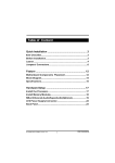
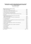
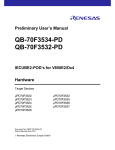
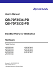
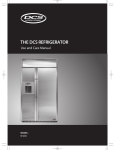
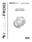
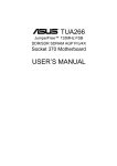
1
Table of Content
Quick Installation .................................................. 3
Before Installation
Layout
Item Checklist
Jumpers/ Connectors
Form Factor
Feature .................................................................. 10
Block Diagram
Specifications
Hardware Setup ................................................... 13
Install the Processor
Install Memory Modules
Back Panel
KD266 Version 1.1A
1
FB11325000000
Chapter 1
Quick Installation
BIOS Setup ........................................................... 17
BIOS Setup
Main Menu
Standard CMOS Features
Advanced BIOS Features
Advanced Chipset Features
Integrated Peripherals
Power Management Setup
PnP/ PCI Configurations
PC Health Status
Iwill Smart Setting
Load Fail Safe Defaults
Load Optimized Defaults
Set Supervisor/ User Password Setting
Save & Exit Setup
Exit Without Saving
2
Chapter 1
Quick Installation
Quick Ins tallation
Before Installation
For installation, you m ay need som e or all of the following tools:
M edium size flat blade screwdriver
M edium size P hillips head screwdriver
A 3/16 inch nut driver or wrench
Users must follow these guidelines to ensure the
motherboard is protected during installation.
1.Make sure your computer is powered-off whenever
working in with inside components
2.The motherboard, like all other electronic equipment, is
ensitive to static. Please take the proper precautions when
handling it. If possible, ground yourself by touching a metal
table or desk. keep the board in its conductive wrapping
until it is configured and ready to be installed in your
system.
3.Keep all magnets away from both your hard and floppy
disk drives, especially magnetic screwdrivers. Keep both
floppy and hard disks apart if disassembled.
4.Keep water and liquids away from your computer and its
components.
3
Chapter 1
Quick Ins tallation
Keyboard
Mo use
Layout
PWR
VIO
PS2_ SB
Fcpu
USB
Fcpu
FD C
CPU Socket
C om 2
parall el
C om 1
USB
Socket462
Faux
KD266
I DE 0
I DE 1
DM3
DM2
PCI1
DM1
AGP
PCI2
PCI4
ALi
M1535D+
ALi
PCI5
PCI6
Tsys Mdm
WOL
Item Checklist
The motherboard
Operation manual
ATA/66/100 cable
Floppy cable
P ower I nstaller CD
Optional
USB riser kit
Therm al Sensor for System
I nfrared port cable
4
USB
Fsys
IR
F ro nt P anel Con nector
C MOS
PCI3
Chapter 1
Quick Installation
Jumpers/Connectors
DRAM Voltage (VIO)
PS2_SB(JP6)
1
2
3
Enabled (Default)
1
2
3
Disabled
1
1
1
2
2
2
3
3
3
Normal (Default) Increase 5% Increase 10%
Clear CMOS
1
1
2
2
3
3
Normal (Default)
1
Clear CMOS
2
System temp
CPU fan
1
2
3
PIN Assignment
1:GND
2:12V
3:Sense
Auxiliary fan
System fan
5
Chapter 1
Quick Installation
Wake On Modem
123
PIN Assignment
1:5VSB
2:GND
3:Control Pin
Wake On LAN
123
PIN Assignment
1:5VSB
2:GND
3:LAN_Wake
Infrared connector(IR)
1
2
3
4
5
6
PIN Assignment
1:VCC
2:FIR
3:IRRX
4:GND
5:IRTX
6:OVCR OFF
6
Chapter 1
Quick Installation
ATX power connector
20
11
10
1
PIN NO
Definition
PIN NO
Definition
1
+3.3v
11
+3.3V
2
+3.3v
12
-12V
3
GROUND
13
GROUND
4
+5V
14
Power Supply On
5
GROUND
15
GROUND
6
+5V
16
GROUND
7
GROUND
17
GROUND
8
P o wer Good
18
-5V
9
+5V Standby
19
+5V
10
+12V
20
+5V
7
Chapter 1
Quick Installation
Front panel connector
1
12
24
Function
PIN NO.
PWR_ON(Power/Soft_off)
1,13
ALED(IDE LED)
7,8
PIN 7:Anode
PIN 8:Cathode
RST(RESET)
11,12
PIN 11:RST
PIN 12:GND
PLED(System Power LED) 15,16,17
SPKR(Speaker)
Definition
PIN 15:VCC
PIN 16:NC
PIN 17:GND
PIN 21:VCC
PIN 22:NC
21,22,23,24
PIN 23:NC
PIN 24:SPEAK(BUZZ)
8
Chapter 1
Quick Installation
Socke t462
PIN
Form Factor
Socket462
305mm
KD266
ALi
M1535D+
ALi
193mm
9
Chapter 2
Feature
Feature
Block Diagram
Sock 462 CPU
AGP 4X/2X
ALi M 1649
North Bridge
Memory Bus
SDRAM
PCI Bus
Clock
Generator
PCI x 6
ALi M 1535D+
Ultra DMA/66/100
LPC
Keyboard/Mouse
Floppy
Parallel
Serial
Game Port
10
Chapter 2
Feature
Specifications
Processor / (Socket A)
Supports 1 processor Socket A
Supports 100MH z/133MH z (Front Side Bus)
Supports AMD Athlon and D uron C P U
CPU Frequency/Voltage Selection
Supports Vcore selection by BIOS (1.125V to 1.85V Step 0.025V)
Supports VIO selection by Jum per (5% or 10%)
Supports C P U Multiplierselection by BIOS (5X to 15X Step 0.5X)
Supports C P U E xternal Frequency selection by BIOS(100MH z-180MH z
Step/MH z)
Memory
Supports P C 100/P C 133 S D R AM
Supports 16M/64M/128M/256Mbit 512 D R AM technology
Supports up to 3GB D R AM
Graphics
Supports AGP 2X/AGP 4X Universal Slot
General I/O
P C I 2.2 com pliance
Supports 32-bit/33MH z P C I interface
Supports ATA33/66/100 ID E interface
Supports Floppy interface
Supports 16550AU AR T interface
Supports E C P /E P P interface
Supports P S2 interface
Supports SIR /C IR /MIR interface
Supports U SB interface
ChipSet
ALi M1649, BGA528
ALi M1535D +, BGA352
11
Chapter 2
Feature
Management
Supports voltage m onitoring (+12V/+5V/Vcore/+3.3V)
Supports fan control signal (C P U /SYS)
Supports tem perature sensor (C P U /SYS)
Supports P ower on by E xt.Modem /Int.Modem /R TC /P ME
Supports R esum e by LAN /E xt.Modem /Int.Modem /P S2Keyboard/P S2
Supports AC P I
Supports AP M/D MI/SMBU S/P nP
Supports BIOS R OM Flash C ontrol
Supports Manually Assign P C I IR Q
Expansion Slot, Sockets and Connectors
One Socket 462 socket
Three D IMM sockets
One Universal AGP slot
Six 32bit/33MH z Bus Master P C I slots
Two ID E connectors
One FD C connector
One E xternal U SBx2 connectors
Others
ATX Form Factor 305m m x193m m
12
Chapter 3
Hardware Setup
Hardware Setup
Install the Processor
The CPU should have a fan attached it to prevent
overheating.
Be sure that there is sufficient air circulation across the
processors heatsink by regularly checking that your CPU fan
is working. Without sufficient circulation, the processor could
overheat and damage both the processor and the
motherboard. You may install an auxiliary fan, if necessary.
Step1:
Step2:
Locate the ZIF socket and open it
by first pulling the lever of socket
upward.
Insert the CPU into the socket.
Please keep the lever right angle
when inserting CPU.
Step4:
Step3:
Push the lever down to close the
socket.
When inserting the CPU Please
note the correct orientation as
shown. The notched corner
should point toward the end of
the lever.
13
Chapter 3
Hardware Setup
Step5:
Attach the heatsink to the CPU.
Be careful not to scrape the motherboard when
mounting a clampstyle processor fan or else damage
may occur to the motherboard.
Step6:
Pu sh th e c lip o f h eat si nk
downward to hock the ear of
socket firmly.
Step7:
Finally,attach the fan cable to the
CPU fan header FCPU.
Don't forget to set the correct Bus Frequency and
Multiple(frequency multiple setting is available only
on unlocked processors) for your Socket 370
processor or else boot-up may not be possible.
14
Chapter 3
Hardware Setup
Install Memory Module
The m otherboard h as three m em ory sockets and supp orts m em ory size
up to 3GB.
Step2:
Step1:
Open latches of DIMM socket.
Proofread the RAM module to the
DIMM Socket.
Step3:
Step4:
Press the latches into the notches of the
RAM module.
Insert the RAM module into the DIMM
socket.
15
Chapter 3
Hardware Setup
Back Panel
Function
color
Description
PS2/Mouse
Green
This connector can be used to support a
PS/2 mouse.
PS2/keyboard
Purple
This connector can be used to support a
PS/2 keyboard.
Universal Serial
Bus
Black
This motherboard has two USB ports, any
USB-compatible peripherals and/or hub
can be connected into either USB port.
Serial port
Teal
One serial port is ready for a modem or
other serial devices.
Parallel port
Burgundy
This connector is used for printers, or
other parallel devices.
16
Chapter 4
BIOS Setup
BIOS Setup
BIOS Setup
Upgrade BIOS
The BIOS can be upgraded from a diskette with the Award Flash utility
— AWDFLASH.E XE . The BIOS im age file, and update utility are
available from IWILL’s WE B site: support.iwill.net
If you have any problem, please contact with us in IWILL’
s web
site:www.iwill.net
Enter BIOS setup program
P ower-on the system by either pressing the P ower-On button, or
by using any of the power-on features provided by the
m otherboard. Then, press the <D el> key after the P ower-On Self
Test (P OST), and before the scanning of ID E devices. Sim ply
look for the m essage “P ress D E L to enter SE TU P ”displayed at
the bottom of the screen during the boot up process. If the
m essage disappears before you’ve had a chance to respond,
you can restart the system by turning off the system power then
turn it on again, or pressing the “R E SE T”button on the system
case, or pressing <C trl>, <Alt> and <D el> keys sim ul taneously.
Generally, the BIOS default settings have been carefully
chosen by IWILL's Engineers provide the absolute
maximum performance and reliability. It is very
dangerous to change any setting without full
understanding. We strongly recommend that you.
DO NOT update BIOS if the system works perfectly.
DO NOT change any setting unless you fully
understand what it means.
17
Chapter 4
BIOS Setup
Using BIOS setup program
Up
Move to the previous field
Down
Move to the next field
Left
Move to the field on the left hand side
Right
Move to the field on the right hand side
<Esc>
Quit from setup program without saving changes,
ro Exit from current menu page and return to
main menu page
<PgUp>or<+>
Select the previous value for a field.
<PgDn>or<->
Select the next value for a field
<F1>
General Help
<F2>
Item Help
<F5>
Previous Values
<F6>
Fail-Safe Defaults
<F7>
Optimized Deaults
<F10>
Save the current value and exit setup program
If the system is no longer able to boot after changing the settings, the only
way to clear the data stored in R TC C MOS. To reset the R TC C MOS data,
take the JP 1 jum per cap off pins 1-2, place onto pins 2-3, an d then place
back onto pin s 1-2 again. it returns the R TC to the default se tting. Then,
get into the BIOS setup program , ch oose Load Fail-Safe D efaults ; Load
Optim ized D efaults, and select IWILL’
s E ngineers to set default settings in
your C MOS.
18
Chapter 4
BIOS Setup
Main Menu
The m ain m enu allows you to select from several setup item s. U se the
arrow keys to select am ong these item s and press <E nter> key to enter
the sub-m enu. Abrief description of each highlighted selection appears
on the bottom of the screen.
CMOS Setup Utility-Copyright(c) 1984-2001 Award Software
Standard CMOS Features
IWILL Smart Setting
Advanced BIOS Features
Load Fail-Safe Defaults
Advanced Chipset Features
Load Optimized Defaults
Integrated Peripherals
Set Supervisor Password
Power Management Setup
Set User Password
PnP/PCI Configurations
Save & Exit Setup
PC Health Status
Exit Without Saving
ESC: Quit
F10: Save & Exit Setup
: Select Item
Time, Date Hard Disk Type...
19
Chapter 4
BIOS Setup
Standard CMOS Features
CMOS Setup Utility-Copyright(c) 1984-2001 Award Software
Standard CMOS Features
Date (mm:dd:yy)
Time (hh:mm:ss)
Fri, Jan 5 2001
15:17:48
Item Help
IDE Primary Master
IDE Primary Slave
IDE Secondary Master
IDE Secondary Slave
[None]
[ None]
[ None]
[ None]
Menu Level
Change the day, month,
year and century
Drive A
[ 1.44M,3.5i n.]
Drive B
[None]
Floppy 3 Mode Support [Disabled]
Video
Halt On
[ EGA/VGA]
[ All Errors]
Base Memory
Extended Memory
Total Memory
640k
31744k
32768k
Date
This field specifies the current date. The date form at is<day>,
<m onth>, <day>, and <year>.
Time
This field specifies the current tim e. The tim e form at is <hour>,
<m inute>, and <second>. The tim e is calculated based on the
24-hour (m ilitary-tim e) clock.
IDE Primary Master / Primary Slave / Secondary Master
/ Secondary Slave
P ress “E nter”to enter next page for detail hard drive setting.
IDE HDD Auto-Detection
Auto-Detect the HDDs Capacity, and its parameters, ex: Cylinder,
Head and Sector.
20
Chapter 4
BIOS Setup
v
I DE Pr imar y M as ter / Pri mary Slave / Second ary M aste r /
Secondary Slave
This field specifies type of drive that corresponds to the driver
installed in your system. If you select User, please specify the
correct number of Cylinders, Heads, and Sectors.
Manual
Select anual lets you set the remaining fields on
this screen. Select the type of fixed disk.
Auto
(Default Vaule)
BIOS automatically fills in the values for the
cylinders, heads and sectors fields.
None
Any Disk Drivers are attached.
Capacity Auto Display your disk drive size
Access M ODE
This field specifies the IDE translation mode.
NORMAL
Specifies traditional CHS addressing mode.
LARGE
Specifies extended CHS translation mode
LBA
Specifies LBA translation mode.
AUTO
BIOS specifies translation method automatically.
(Default Vaule)
Cylinders
Set the number of cylinders for this hard disk.
Heads
Set the number of read/write heads
Precomp
Write precompensation.
Sectors
Set the number of sectors per track
21
Chapter 4
BIOS Setup
Drive A / Drive B
This field specifies the traditional type of floppy drives.
None
(*Drive B default)
Any Floppy drive is connected
360K, 5.25 in.
Specifies extended CHS translation mode
1.2M, 5.25 in.
A 1.2M floppy drive is connected
720K, 3.5 in.
A 720K floppy drive is connected.
1.44M, 3.5 in.
(*Drive A default)
A 1.44M floppy drive is connected
2.88M, 3.5 in.
A 2.88M floppy drive is connected
Floppy 3 Mode Support
3 Mode floppy drive is a type of 3.5-inch drive used by N E C P C 98
com puters. It supports both 1.2M and 1.44M form ats using the
sam e drive. This field specifies which drive supports 3 Mode.
When a floppy drive is specified to support 3 Mode, the
respective drive setting in “D rive A/ D rive B”field will be invalid.
Disabled
(Default Value)
No 3 Mode drive is connectedd
Drive A
A 3 Mode drive is connected as drive A
Drive B
A 3 Mode drive is connected as drive B
Both
Both drive A and drive B are 3 Mode drives
Video
EGA/VGA
(Default Value)
Specifies EGA or VGA adapter.
CGA 40
Specifies CGA adapter with 40 column mode
CGA 80
Specifies CGA adapter with 80 column mode
MONO
Specifies Monochrome adapter
22
Chapter 4
BIOS Setup
Halt On
All Errors
(Default Value)
Each time the BIOS detects a non-fatal error,
the system will stop and display an error
message.
No Errors
The system will stop for any errors that are
detected.
All, But Keyboard
The system will stop for any errors except
keyboard error.
All, But Diskette
The system will stop for any errors except
diskette error.
All, But Disk/Key
The system will stop for any errors except
diskette and keyboard errors.
Base Memory
The P OST (P ower-On Self Test) determ ines the am ount of base
(conventional) m em ory installed in the system . The value of the
base m em ory is typically 640K. This field has no options.
Extended Memory
The BIOS determ ines how m uch extended m em ory is present
during the P OST. The am ount of m em ory is located above 1MB
in the processor’s m em ory address m ap. This field has no
options.
Total Memory
D isplay the total m em ory available in the system .
23
Chapter 4
v
BIOS Setup
Advanced BIOS Features
CMOS Setup Utility-Copyright(c) 1984-2001 Award Software
Advanced BIOS Features
[Disabled]
[Enabled]
[Enabled]
[Disabled]
[Enabled]
[Floppy]
[HDD-0]
[SCSI]
[Enabled]
[Disabled]
[Enabled]
[On]
[Fast]
[Disabled]
6
250
[Setup]
[Non-OS2]
[No]
[Enabled]
[Disabled]
[Disabled]
[Disabled]
[Disabled]
[Disabled]
[Disabled]
24
Item Help
Menu Level
Allows you to choose
the VIRUS warning
feature for IDE Hard
Disk boot sector
protection. If this
function is enabled
and someone attempt
to write data into this
area, BIOS will show
a warning message on
screen and alarm beep
Chapter 4
BIOS Setup
Virus Warning
When this function is enabled and any attem pt to write data into
this area is m ade, the BIOS m onitor will display a warning
m essage on screen and beep. If you want to run an anti-virus
program , we recom m end you that it will disable and appear the
Virus Warning function beforehand.
[E nabled,D isabled(Default Value)]
CPU Internal Cache
This field configures the C P U internal cache (L1 cache).
[E nable(Default Value),D isabled]
External Cache
This field configures the system ’s external cache (L2 cache).
[E nable(Default Value),D isabled]
CPU L2 Cache ECC Checking
This field specifies whether the C P U L2 cache supports E C C or
not.
[E nable,D isabled(Default Value)]
Quick Pow er On Self Test
This field allows the system to skip certain tests while booting.
This will decrease the tim e to need booting the system .
[E nable(Default Value),D isabled]
First / Secound / Third / Boot Other Device
The BIOS attem pts to load the operating system from the devices
in the sequence selected in these item s.
[Floppy,LS120,H D D -0,SC SI,C D R OM,H D D -1,H D D -2,H D D -3,
ZIP 100,U SB-FD D ,U SB-ZIP,U SB-C D R OM,U SB-H D D ,LAN ,
D isabled]
Sw ap Floppy Drive
Setting to E nabled,floppy drives Aand B will be exchange.
[E nable,D isabled(Default Value)]
25
Chapter 4
BIOS Setup
Boot Up Floppy Seek
Seek disk drives during boot up. D isabling speeds boot up.
[
Enabl
e(Default Value),D isabled]
Boot Up NumLock Status
This field determ ines the configuration of the num eric keypad
after system boot up. If On, the keypad uses num bers keys. If
Off, the keypad uses arrow keys.
[ON (Default Value),Off]
Gate A20 Option
This field configures how the gate A20 is handled. The gate A20
is a device used to address m em ory above 1 MB. At first, the
gate A20 was handled from a pin on the keyboard. While som e
keyboards still provide this support, it is m ore com m on, and
m uch faster, for m odern system chipsets to provide support for
gate A20.
[Fast (Default Value):Gate A20 signal supported by core logic.]
[N orm al:GateA20 signal supported by keyboard controller]
Typematic Rate Setting
This field determ ines if the typem atic rate is to be used. When
enabled, the BIOS will report (after a m om ent) that the key has
been depressed repeatedly. When disabled, the BIOS will report
only once if a key is held down continuously. This feature is
used to accelerate cursor m ovem ents using the arrow keys.
[E nable, D isabled(Default Value)]
Typematic Rate (Chars/Sec)
When Typem atic R ate Setting is enabled, this field specifies how
m any characters will be displayed in one second when a key is
held down continuously.
[6 (D efault Value)8,10,12,15,20,24,30]
Typematic Delay (Msec)
Typem atic delay allows you to select the tim e delay between
when the key is first pressed and when the acceleration begins.
[250m sec (Default Value)500m sc,750m sec,1000m sec]
26
Chapter 4
BIOS Setup
Security Option
This field configures how the system security is handled. It works
conjunction with SE TTIN G SU P E R VISOR / U SE R PASSWOR D
page to control the security level of the system .
[Setup (Default Value):System needs a password to enter BIOS
setup program .]
[System :System needs a password to boot]
OS Select for DRAM >64MB
This field allows you to access the m em ory that is over 64MB
under OS/2.
[OS2, N on-OS2(Default Value)]
Report No FDD For WIN 95
For a floppy diskless system that runs Windows 95, this field
should be set to Yes.
[YE S,N O (Default Vaue)]
Video BIOS Shadow
Setting to enabled, the video BIOS will be copied to the system
m em ory and increase vi deo speed accordingly.
[E nable(Default Value),D isabled]
C8000-CBFFF / CC000-CFFFF / D0000-D3FFF / D4000D7FFF / D8000-DBFFF / DC000-DFFFF Shadow
Setting to enabled, the extended R OM data located at the
respective address range will be copied to system m em ory.
[E nable, D isabled (Default Value)]
27
Chapter 4
BIOS Setup
Advanced Chipset Features
This setup page is used to specify advanced features available through
the chipset. The default settings have been chosen carefully for m ost
operating conditions. D O N OT change the value of any field in this setup
page without full understanding.
CMOS Setup Utility-Copyright(c) 1984-2001 Award Software
Advanced Chipset Feature
DRAM Timing Select
AT Bus Clock
System BIOS Cacheable
Video RAM Cacheable
AGP Aperture Size
AGP Delay Stage
Memory Hole At 15M-16M
I/O Recovery Period
Passive Release
[Press Enter]
[CLK2/4]
[Enabled]
[Disabled]
[64MB]
[6]
[Disabled]
[1 us]
[Disabled]
28
Item Help
Menu Level
Chapter 4
BIOS Setup
DRAM Timing Select
The first chipset settings deal with C P U access to dynam ic
random access m em ory (D R AM). The default tim ings have been
carefully chosen and should only be altered if data is being lost.
Such a scenario m ight well occur if your system had m ixed
speed D R AM chips installed. Longer delays m ight result,
however this preserves the integrity of the data held in the slower
m em ory chips.
SDR DRAM CAS Select
Select the number of clock cycles of CAS latency depends on
the DRAM timing .
[2,3 (Default Value)]
Refresh Queue
Select the depth value of the DRAM refresh queue.
[Disabled,Depth 2,Depth 4,Depth 8 (Default Value)]
DRAM Performance
Select the performance parameter of the installed DRAM. Do not
reset this field from the default value by the system designer
unless you install new memory that has a different performance
rating than the original DRAMs.
[Failsafe,slow, Normal(Default Value) Fast,Ultra,Ultra2]
Enhance Page M ode Timer
Select the preset value of the Page Life Timer counter . When
disabled , the open pages mode will not be closed even the PLT
counter expired .
[16clk,32clk, (Default Value) 64clk,128clk,Disabled]
Refresh Rate
Select the rating for DRAM refresh control.
[Normal(Default Value),15.6us,7.8us]
AT bus Clock
Select the speed of the AT bus in term s of a fraction of the C P U
clock speed , or at the fixed speed of 7.16 MH z.
[7.16MH z,C LK2/2,C LK2/3,C LK2/4(Default Value),C LK2/5,C LK2/6]
System BIOS Cacheable
Setting to enabled, accesses to the system BIOS will be cached.
[E nable(Default Value), D isabled]
29
Chapter 4
BIOS Setup
Video RAM Cacheable
Setting to enabled, access to the Video R AM will be cached.
[E nable,D isabled(Default Value)]
AGP Aperture Size
This field configures the m ain m em ory size for AGP graphics data
used.
[0MB,1MB,2MB,4MB,8MB,16MB,32MB,64MB,(Default Value),
128MB,256MB]
Memory Hole At 15-16M
This system m em ory area can be reserved for ISAadapter R OM.
When reserved, this area cannot be cached. P lease refer to
inform ation regarding the m em ory requirem ents of your system
peripherals.
[E nable,D isabled(Default Value)]
I/O recovery Period
It allows you to determ ine the recovery tim e allowed for I/O.
[3us,2us,1us(Default Value)]
Passive Release
Setting to enabled, C P U to P C I bus accesses is allowed during
passive release. Otherwise, the arbiter only accepts another P C I
m aster access to local D R AM.
[E nable,D isabled(Default Value)]
30
Chapter 4
BIOS Setup
Integrated Peripherals
CMOS Setup Utility-Copyright(c) 1984-2001 Award Software
Integrated Peripherals
OnChip IDE Channel0
OnChip IDE Channel1
Primary Master
PIO
Primary Slave
PIO
Secondary Master PIO
Secondary Slave PIO
Primary Master
UDMA
Primary Slave
UDMA
Secondary Master UDMA
Secondary Slave UDMA
OnChip USB Port
USB Keyboard Under DOS
Init Display First
IDE HDD Block Mode
POWER ON Function
kB Power ON Password
Hot Key Power ON
Onboard FDC Controller
Onboard Serial Port 1
Onboard Serial Port 2
Onboard Serial Port 3
UART Mode Select
RxD , TxD Active
IR Duplex Mode
Fast IR Mode Use DMA
Onboard Parall el Port
Parallel Port Mode
ECP Mode Use DMA
[Enabled]
[Enabled]
[Auto]
[Auto]
[Auto]
[Auto]
[Auto]
[Auto]
[Auto]
[Auto]
[Disabled]
Disabled
[AGP]
[Enabled]
[BUTTON ONLY]
Enter
Ctrl-F1
[Enabled]
[3F8/IRQ4]
[2F8/IRQ3]
[Disabled]
IrDA
Hi , Lo
Half
1
[378/IRQ7]
[SPP]
3
Item Help
Menu Level
On-Chip IDE Channel0/1
This field enables or disables the onboard ID E controller.
[E nable(Default Value), D isabled]
IDE Primary Master / Slave PIO
IDE Secondary Master / Slave PIO
These fields configure the P IO (P rogram m able Input Output)
transfer m ode for each ID E devices. The m axim um transfer rates
of each P IO m ode are listing as follow:
31
Chapter 4
BIOS Setup
PIO
PIO
PIO
PIO
PIO
Mode
Mode
Mode
Mode
Mode
0
1
2
3
4
Auto(Default Value)
Mode 0
Mode 1
Mode 2
Mode 3
Mode 4
3.3 MB/sec
5.2 MB/sec
8.3 MB/sec
11 MB/sec
16.6 MB/sec
Negotiated with device automatically
Use Mode 0 timing to access device
Use Mode 1 timing to access device
Use Mode 2 timing to access device
Use Mode 3 timing to access device
Use Mode 4 timing to access device
IDE Primary Master / Slave UDMA
IDE Secondary Master / Slave UDMA
I f you select Auto, the ID E controller uses U ltra D MA33/66 Mode
to access U ltra D MA-capable ID E devices. D epend on the resent
of negociation with your H D D . The m axim um transfer rate of U ltra
D MA 66 Mode is 66.6 MB/sec.
[Auto(Default Value), D isabled]
Onchip USB port
Select E nabled if your system contains U SB peripherals.
[E nable, D isabled(Default Value)]
USB Keyboard under DOS
Select to E nabled if you want to use U SB keyboard under D OS.
[E nable, D isabled(Default Value)]
Init Display First
This item allows you to decide which slot to activate first, either
P C I slot or AGP slot.
[P C I Slot, AGP (Default Value)]
IDE HDD Block Mode
When enabled, the ID E controller will use the faster block m ode
to access devices.
[E nabled(Default Value), D isabled]
32
Chapter 4
BIOS Setup
Pow er-On Function
This field configures the P ower-On m ode of the system .
The P ower-On button will not function in this m ode.
Password
You can assign a password string through KB
Power-On Pass word field.
Hot KEY
You can assign a hot key through the Hot Key
Power-On field.Pressing this hot key will poweron your system.
Mouse Left / Right Double - Clicking The PS/2 mouse Left / Right
button will power on the system .
Button only
(Default Value)
Simply power-on your system by pressing the
Power-On button on the front panel of your PC
case
Keyboard 98
Enables Keyboard 98 function.This founction is
good only for users of Keyboard 98.
KB Pow er-On Passw ord
If you wish to use this function, bring the cursor to the field written
E nter, then press <E nter>. The com puter will display the
m essage, E nter P assword”. Type your password is displayed,retype your password. The KB P ower-On function will be in effect
after you save and exit setup.
To disable a password, bring the cursor to the E nter”field again,
then press <E nter>. The com puter will display the m essage,
E nter P assword P ress <E nter>. A m essage will confirm that the
password is disabled.
Hot Key Pow er-On
This field specifies key selection for the Keyboard-P ower-On hot
key.
[C trl-F1,C trl-F2,C trl-F3,C trl-F4,C trl-F5,C trl-F6,C trl-F7,C trl-F8,C trlF9, C trl-F10,C trl-F11,C trl-F12]
Onboard FDC Controller
This field enables or disables the onboard floppy controller.
[E nabled(Default Value),D isabled]
33
Chapter 4
BIOS Setup
Onboard Serial Port 1 / 2 / 3
These fields configure the onboard serial ports. There are
several port addresses and IR Q channels to select from .
3F8 / IRQ 4
(Default Vaule)
Port address 3F8h, IRQ 4
2F8 / IRQ 3
Port address 2F8h, IRQ 3
3E8 / IRQ 4
Port address 3E8h, IRQ 4
2E8 / IRQ 3
Port address 2E8h, IRQ 3
Auto
BIOS assigns port address and IRQ channel
automatically.
Disabled.
Disables serial port
UART Mode Select
[IrD A(Default Value),ASKIR ]
RxD, TxD Active for IrDA and ASKIR Functions
When setting the field to either IrD Aor ASKIR , you m ust select the
active level of receiving and transm ission signal.
[H i ,Lo(D efault Value) /Lo,H i/Lo,Lo/H i,H i]
IR Duplex Mode
[Full,H alf(Default Value)]
Fast IR Mode Use DMA
[1(Default Value),3]
Onboard Parallel Port
This field configures the onboard parallel port. There are several
port addresses and IR Q channels to select from .
378 / IRQ 7
Port address 378h, IRQ 7
(Default Value)
278 / IRQ 5
Port address 278h, IRQ 5
3BC / IRQ 7
Port address 3BCh, IRQ 7
Disabled
Disables parallel port
34
Chapter 4
BIOS Setup
Parallel Port Mode
This field configures the operating m ode of an onboard parallel
port. E nsure you know the specifications of your parallel port
devices before selecting field.
[SP P (Default Value),E P P,E C P E C P +E P P ]
ECP Mode Use DMA
When the P aral lel P ort Mode field is configured as E C P,
E C P +E P P m ode, it needs a D MAchannel for data transfer. This
field specifies the D MAchannel for E C P parallel port use.
[1:U se D MAchannel 1]
[3(Default Value):U se D MAchannel 1]
35
Chapter 4
BIOS Setup
Power Management Setup
CMOS Setup Utility-Copyright(c) 1984-2001 Award Software
Power Management Setup
Power Mangemen
PM Control by APM
MODEM Use IRQt
Video Off In Suspend
Video Off Method
[User Define]
[No]
[3 ]
[Yes]
[V /H SYNC+Blank]
PM Timers
APM HDD Power Down Timer
APM Suspend Timer
PWR-OFF Mode by PWR-BTTN
Wake Up by PCI Card
Wake Up by Ring/LAN
PWROn/Resume by Alarm
Date (of Moth) Alarm
Time (hh:mm:ss) Alarm
[Disabled]
[Disabled]
[Instant-Off]
[Disabled]
[Disabled]
[Disabled]
0
0
0
0
**Reset APM Timer Events**
IRQ[1] ( KeyBoard )
IRQ[3]
IRQ[4]
IRQ[5]
IRQ[6] ( Floppy Disk )
IRQ[7]
IRQ[8 (
RTC
)
IRQ[9]
IRQ[10]
IRQ[11]
IRQ[12] (PS2 Mouse
)
IRQ[14] (Primary IDE )
IRQ[15] (Secondary IDE)
[Enabled]
[Disabled]
[Disabled]
[Disabled]
[Disabled]
[Disabled]
[Disabled]
[Disabled]
[Disabled]
[Disabled]
[Enabled]
[Disabled]
[Disabled]
Item Help
Menu Level
E ach power-saving m ode has a respective tim er. The value of the
tim er can be assigned or reloaded and it will count down to zero.
When the tim er equals to zero, the system will be forced into the
related suspend or power-saving m ode. If any predefined signal or
event is detected during the tim er counting period, the tim er restarts
autom atically.
36
Chapter 4
BIOS Setup
Pow er Management
This feature allows the user to select the default param eters for
the power-saving m ode.
Min Saving:
When idle for one hour,the system enters suspend m ode.
Max Saving:
When idle for fifteen m inutes, the system enters suspend m ode.
U ser D efine(Default Value):
U ser can specify the tim e the system enters suspend m ode.
PM Control by APM
Setting to enabled, an Advanced P ower Managem ent (AP M)
protocol will be activated to handle the power-saving m ode.
[N O(Default Value),Yes]
MODEM Use IRQ
This determ ines the IR Q in which the MOD E M can use.
[N A, 3 (D efault Value),4,5,7,9,10,11]
Video Off In Suspend
This determ ines the m anner in which the m onitor is blanked.
[N O , Yes (Default Value)]
Video off Method
V/H SYN C +Blank (Default Value):
Turn off the vertical and horizontal synchronization ports and write
blanks to the video buffer.
Blank Screen:
Write blanks to the video buffer only.
D P MS:
Initial display power m anagem ent signaling with D P MS.
APM HDD Pow er Dow n Timer
This field specifies the tim e the system enters H D D power down.
It is available only when the P ower Managem ent field is set to
U ser D efine.
[1Min,2Min,3Min,4Min,5Min,6Min,7Min,8Min,9Min,10Min,11Min,
12Min,13Min,14Min,15Min, D isabled(Default Value)]
37
Chapter 4
BIOS Setup
APM Suspend Timer
This field specifies the tim e the system enters power-saving
m ode. It is available only when the P ower Managem ent field is
set to U ser D efine.
[1Min,2Min,4Min,8Min,12Min,20Min,30Min,40Min,1H our,
D isabled(Default Value)]
PWR-Off Mode by PWR-BTTN
This field specifies the function of power button.
Instant-Off (Default Value):
When power button pressed, the system turns off im m ediately,
D elay4 Sec:
After the power button has been pressed and held for four
seconds,the system turns off.
Wake up by PCI card
When enabled , you can "wake-up " your system using P C I rev.2.2
card , when a "P ME " event occuring.
[E nabled,D isabled(Default Value)]
Wake up by Ring / LAN
When enabled , the system can " power-on" or "wake-up" through
LAN (Local Area N etwork ) or an external m odem connected to the
PC.
[E nabled,D isabled(Default Value)]
PWROn / Resume by Alarm
When enabled , you can set the date and tim e to autom atically
"power-on" or "wkae-up" your P C (sim ilar to an alarm clock).
E nabled:
Setting to D ate (0-31) and Tim er (hr,m in,sec) to power-on the P C .
When date is set to 0, the Tim er is set for every day.
D isabled (Default Value):
D isable R TC alarm function.
IRQ1~IRQ14
If set to E nab led, the spe cified IR Q l ine wi ll pre vent the sys tem
from entering power saving m odes.
E nables or disables the m onitoring of the specified IR Q line.
38
Chapter 4
BIOS Setup
PnP/ PCI Configurations
CMOS Setup Utility-Copyright(c) 1984-2001 Award Software
PnP/PCI Configurations
PNP OS Installed
Reset Configuration Data
[No]
[Disabled]
Resources Controlled By
IRQ Resources
[Auto (ESCD)]
Press Enter
PCI/VGA Palette Snoop
PCI IRQ Actived By
[Disabled]
[Level]
Item Help
Menu Level
Select Yes if you are
using a Plug and Play
capable operation
system Select No if
you need the BIOS to
configure non-boot
devices
PNP OS Installed
The field specifies whether a P lug and P lay operating system is
installed.
[Yes, N o(Default Value)]
Reset Configuration Data
N orm ally, you leave this field D isabled. Select E nabled to reset
E xtended System C onfiguration D ata (E SC D ) when you exit
Setup if you have installed a new add-on and the system
reconfiguration has caused such a serious conflict that the
operating system can not boot.
[E nabled,D isabled(Default Value)]
39
Chapter 4
BIOS Setup
Resources Controlled By
The Award P lug and P lay BIOS has the capacity to autom atically
configure all the boot and P lug and P lay com patible devices.
H owever, this capability m eans a bsolutely nothing unless you are
using a P lug and P lay operating system such as Windows98/95/
N T. If you set this field to “m anual”choose specific resources by
going into each of the sub m enu that follows this field (a sub
m enu is preceded by a “Ø”).
[Manual:R esources con trolled by the user.]
[Auto(E SC D ) (Default Value):R esources controlled by BIOS
autom atically.]
IRQ Resources
P ress<E nter> and you will enter the sub-m enu of this item .
This item is adjustable only when Resources Controlled By is set
to Manual.
PCI / VGA Palette Snoop
This field controls the ability of a prim ary P C I graphics controller
to share a com m on palette with an ISA/VE SAvideo or MP E G card.
[E nabled:P C I VGAco-works with ISAMP E G card.]
[D isabled (Default Value): All cases except above.]
PCI IRQ Actived By
This sets the m ethod by which the P C I bus recognizes that an
IR Q service is being requested by a device. Under all
circum stances, you should retain the default configuration unless
advised otherwise by you r system ’s m anufacturer.
[Level (Default Value),E dge]
40
Chapter 4
BIOS Setup
PC Health Status
This page is the current status of your com puter. On the screen
displays CP U/System tem perature, FAN speed and voltages.
CMOS Setup Utility-Copyright(c) 1984-2001 Award Software
PC Health Status
CPU Warning Temperature
Current CPU Temperature
Current SYS Temperature
Current CPUFAN Speed
Current SYSFAN Speed
Vcore.
+3.3v
+ 5v
+ 12v
Shutdown Temperature
[Disabled]
47 C/116 F
35 C/95 F
4571 RPM
0 RPM
1.80V
3.39V
5.01V
12.20V
[70 C/158 F]
Item Help
Menu Level
CPU Warning Temperature
When C P U tem perature reaches the specified standard , the
system will issue a warning and allows you to prevent the C P U
overheat problem .
[D isabled (Default Value),50*C /122 *F,53*C /127*F,56 *C /13*F,
60*C /147*F,6 3*C /145*F,66*C /151*Fand 70*C /158*F]
41
Chapter 4
BIOS Setup
Iwill Smart Setting
CMOS Setup Utility-Copyright(c) 1984-2001 Award Software
IWILL Smart Setting
THE CPU IS
THE CPU ID IS
CPU Micro Code Updated to
Item Help
Menu Level
Spread Spectrum
=**= IWILL Micro Stepping
CPU Clock
CPU Clock Ratio
PCI Clock Divider
CPU Vcore Setting
BIOS-ROM Flash Protect
=**=
Over-clocking is not guaranteed. Users must have
substantial knowledge of proper CPU relative to
adjusting CPU speeds. Over-clocking should be done
only by experienced engineers who conduct tests.
Iw ill MicroStepping
MicroStepping
Microstepping is Iwill's another step forward to provides users a
fuss free C P U frequency set up procedure. It contains two m ain
functions, Auto D etecting C P U s speed and Micro Adjustable C P U
FSB speed.
Auto Detecting CPU speed:
IWILL MicroStepping will auto detect the C P U 's factory m ultiplier
setting and C P U FSB to the factory default. This function provides
a "fuss free" C P U set up process for the general users.
42
Chapter 4
BIOS Setup
Micro Adjustable CPU FSB speed:
IWILL provides a user friendly overclocking function that allows
users to experience the fun of overclocking. This function allows
user to adjust C P U FSB by 1MH z interval. This is particularly
useful when user wants to extract the m ost out of the purchased
C P U . For exam ple: you select from 133, 134, 135, 136, 137,
138MH z and up to the m axim um speed that the system can
sustained.
In the tim e should overclocking failed, MicroStepping will auto
detects the C P U 's factory m ultiplier setting and set the C P U FSB
to default 66MH z, to protect the C P U installed.
To understand how does CPU w orks, and how does it
related to FSB and m ultiplier, here is the exam ple:
C P U speed = FSB x Multiplier (C P U R atio)
800Mhz = 100Mhz x 8
Spread Spectrum
This item configures radiation em itted from the system . When
enabled, system will release less radiation.
[E nabled,D isabled (Default Value)]
PCI Clock Divider
This item is P C I clock frequency.
For exam ple: Auto =>autom atically
C P U /3 => C P U =100,100/3=33.3
C P U /4 => C P U =133,133/4=33.3
[Auto (Default Value),C P U /3,C P U /4]
CPU Vcore Setting
This item display the current status of C P U voltages.
[Auto (Default Value), 1.125V, 1.150V, 1.1 75V, 1.200V,1.225V,
1.250V,1.275V,1.300V,1.325V,1.350V,1.375V,1.400V,1.425V,
1.450V,1.525V,1.550V,1.575V,1.600V,1.625V,1.650V,1.675V,
1.700V,1.725V,1.750V,1.775V,1.800V,1.825V,1.850V]
BIOS-ROM Flash Protect
When select”N on flash”, the BIOS R OM chip will be protecte to
prerent injuring by Virus “please don’tselect Flashable”until
you have to upgrade the latest BIOS.
[N on flash (Defult Value),Flashable]
43
Chapter 4
BIOS Setup
Load Fail Safe Defaults
When you press <E nter> on this item you get a confirm ation dialog box
with a m essage sim ilar to: P ressing ‘
Y’loads the BIOS default values
for the m ost stable, m inim al-perform ance system operations.
CMOS Setup Utility-Copyright(c) 1984-2001 Award Software
Standard CMOS Features
IWILL Smart Setting
Advanced BIOS Features
Load Fail-Safe Defaults
Advanced Chipset Features
Load Optimized Defaults
Integrated Peripherals
Set Supervisor Password
Power Management Setup
Set User Password
Load Fail-Safe Defaults(Y/N)?
N Setup
PnP/PCI Configurations
Save & Exit
PC Health Status
Exit Without Saving
ESC: Quit
F10: Save & Exit Setup
: Select Item
Time, Date Hard Disk Type...
44
Chapter 4
BIOS Setup
Load Optimized Defaults
When you press <E nter> on this item you get a confirm ation dialog box
with a m essage sim ilar to:
CMOS Setup Utility-Copyright(c) 1984-2001 Award Software
Standard CMOS Features
IWILL Smart Setting
Advanced BIOS Features
Load Fail-Safe Defaults
Advanced Chipset Features
Load Optimized Defaults
Integrated Peripherals
Set Supervisor Password
Power Management Setup
Set User Password
Load Optimized Defaults
PnP/PCI Configurations
Save(Y/N)?N
& Exit Setup
PC Health Status
Exit Without Saving
ESC: Quit
F10: Save & Exit Setup
: Select Item
Time, Date Hard Disk Type...
45
Chapter 4
BIOS Setup
Set Supervisor/ User Passw ord Setting
These setup pages are used for password setting. When a password
has been enabled and the Security Option field is set as Setup, you will
be required to enter the password every tim e you try to enter BIOS Setup
program . This prevents an unauthorized person from changing any part
of your system configuration. Additio nally, if the Security Option field is
set as Boot, the BIOS will request a password every tim e your system
boot. This would prevent unauthorized use of your com puter.
If you wish to use this function, bring the cursor to this field, then press
<E nter>. The com puter will display the m essage, “E nter P assword”.
Type your password and press <E nter>. After the m essage onfirm
P assword”is displayed, re-type your password. The Supervisor
P assword function will be in effect after you save and exit setup.
To disable a password, bring the cursor to this field, then press <E nter>.
The com puter will display the m essage, “E nter P assword”. P ress
<E nter>. Am essage will confirm that the password is disabled. Once
the password is disabled, the system will boot and you can enter setup
program freely.
CMOS Setup Utility-Copyright(c) 1984-2001 Award Software
Standard CMOS Features
IWILL Smart Setting
Advanced BIOS Features
Load Fail-Safe Defaults
Advanced Chipset Features
Load Optimized Defaults
Integrated Peripherals
Set Supervisor Password
Power Management Setup
Set User Password
Enter Password:
PnP/PCI Configurations
Save & Exit Setup
PC Health Status
Exit Without Saving
ESC: Quit
F10: Save & Exit Setup
: Select Item
Time, Date Hard Disk Type...
46
Chapter 4
BIOS Setup
Save & Exit Setup
Save current C MOS value and exit BIOS setup program .
CMOS Setup Utility-Copyright(c) 1984-2001 Award Software
Standard CMOS Features
IWILL Smart Setting
Advanced BIOS Features
Load Fail-Safe Defaults
Advanced Chipset Features
Load Optimized Defaults
Integrated Peripherals
Set Supervisor Password
Power Management Setup
Set User Password
PnP/PCI SAVE
Configurations
Save & Exit
to CMOS and EXIT(Y/N)?
Y Setup
PC Health Status
Exit Without Saving
ESC: Quit
F10: Save & Exit Setup
: Select Item
Time, Date Hard Disk Type...
47
Chapter 4
BIOS Setup
Exit Without Saving
Abandons all C MOS value changes and exits BIOS setup program .
CMOS Setup Utility-Copyright(c) 1984-2001 Award Software
Standard CMOS Features
IWILL Smart Setting
Advanced BIOS Features
Load Fail-Safe Defaults
Advanced Chipset Features
Load Optimized Defaults
Integrated Peripherals
Set Supervisor Password
Power Management Setup
Set User Password
PnP/PCI Configurations
Save & Exit Setup
Quit Without Saving (Y/N)?N
PC Health Status
Exit Without Saving
ESC: Quit
F10: Save & Exit Setup
: Select Item
Time, Date Hard Disk Type...
48