1
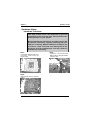
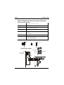
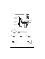
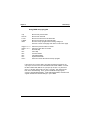
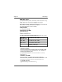
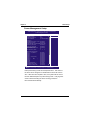
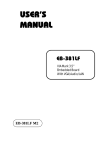
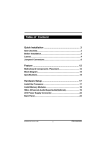
Table of Content
Quick Installation .................................................... .3
Item Checklist...............................................................................3
Before Installation........................................................................3
Layout...........................................................................................4
Jumpers/ Connectors..................................................................6
Feature ................................................................... 12
Motherboard Components Placement......................................12
Block Diagram..............................................................................14
Specifications..............................................................................15
Hardware Setup ..................................................... 17
Install the Processor..................................................................17
Install Memory Modules..............................................................18
IWILL 6Channels Audio/SuperAudio(Optional)..........................19
ATX Power Supply Connector....................................................22
Back Panel...................................................................................23
KA266plus-R/KA266plus Version 1.0A
1
FB01324020000
Chapter 1
Quick Installation
BIOS Setup ............................................................. 24
BIOS Setup.................................................................................24
Main Menu...................................................................................26
Standard CMOS Features..........................................................26
Advanced BIOS Features ...........................................................30
Advanced Chipset Features........................................................33
Integrated Peripherals...............................................................36
Power Management Setup..........................................................40
PnP/ PCI Configurations.............................................................43
PC Health Status.........................................................................45
IWILL Smart Setting....................................................................45
Load Fail Safe Defaults..............................................................48
Load Optimized Defaults............................................................48
Set Supervisor/ User Password Setting....................................49
Save & Exit Setup.......................................................................50
Exit Without Saving....................................................................50
On board Audio ...................................................... 51
Audio Features............................................................................51
Driver Installation.......................................................................53
The Audio Rack..........................................................................55
2
Chapter 1
Quick Installation
Quick Installation
Item Checklist
[ V]
[V]
[V]
[V]
[V]
[ V]
The Motherboard
Operation manual
ATA 100/66 IDE cable
Floppy cable
Power Installer CD
6-Channel Audio (Bracket)
Optional
IWILL SuperAudio (for SPDIF)
USB riser kit
Thermal Sensor for System
Infrared port cable
Before Installation
Users must follow these guidelines to ensure the
motherboard is protected during installation.
1.Make sure your computer is powered-off.
2.The motherboard, like all other electronic equipment,
is sensitive to static. Please take the proper precautions
when handling it. If possible, ground yourself by touching a
metal table or desk. keep the board in its conductive
wrapping until it is configured and ready to be installed in
your system.
3.Keep all magnets away from both your hard and floppy
disk drives, especially magnetic screwdrivers. Keep both
floppy and hard disks apart if disassembed.
4.Keep water and liquids away from your computer and its
components.
3
Chapter 1
Quick Installation
Layout
PWR
JP25
J42
J39
IDE1
IDE 0
JP10
ALiMAGiK1
M1647
KA266plus-R
EXT_IDE0 EXT_IDE1
JP31
AGP
PCI1
PCI2
J53
J45
RAID 100
C MI8738
J43
FDC
JP1
JP 19
C 3DX
H SP56
PCI3
ALi
M 1535 D+
J54
PCI4
JP20
J64
PCI5
J34A
J69
J46
J41
4
Chapter 1
Quick Installation
Connectors/Panel and Jumper Definition
JP1 (Clear CMOS Function)
JP10 (VIO )
JP19 (RAID)
JP20 (Audio Jumper)
JP25 (Keyboard Power On)
JP31 (Front Side Bus)
J34A (EXT_USB)
J39 (CPU Fan)
J41 (System Fan)
J42 (Auxiliary Fan)
J43 (Front Panel Connector)
J45 (Infrared Connector)
J46 (Wake-ON-LAN)
J53 (AUX_IN)
J54 (CD_IN)
J64 (SPDIF and 6 Channel Bracket [Optional])
J69 (Wake-ON-MODEM)
5
Chapter 1
Quick Installation
Jumpers/Connectors
JP1 JP19
JP1 (Clear CMOS)
1
2
3
1
2
3
Normal
(Default)
Clear CMOS
JP19 (RAID)
1
2
3
1
2
3
Enabled
(Default)
Disabled
JP10
JP10 (VIO)
456
123
2.5V
(Default)
6
456
456
123
123
2.6V
2.7V
Chapter 1
Quick Installation
JP25(Keyboard Power On)
123
123
Disabled
(Default)
Enabled
JP31(Front Side Bus)
123
123
FSB100MHz FSB133MHz
(Default)
JP20(Audio Jumper)
123
123
Enabled
(Default)
Disabled
J45(Infrared Connector)
1
2
3
4
5
6
7
Pin Assignment
1: 5V
2: NC
3: IRRX
4: GND
5: IRTX
6: OVCR OFF
Chapter 1
Quick Installation
J64
[SPDIF & 6 Channel (Optional)]
6 CH bracket
2 4 6 8 10121416
1 3 5 7 9 111315
SPDIF
Pin Assignment
1: +12V
2: NC
3: NC
4: SPDIFO
5: SPDIFI
6: GND
7: NC
8: SPGPIO
9: NC
10: NC
11: BASS
12: XREARR
13: GND
14: GND
15: CENTER 16: XREARL
J54 (CD_IN)/ J53 (AUX_IN)
1 2 3 4
PIN Assignment
1: Left Channel
2: GND
3: GND
4: Right Channel
J34A (External USB)
10
8
6
4
2
8
9
7
5
3
1
PIN Assignment
1: 5V
2: 5V
3: USBDT2- 4: USBDT35: USBDT2+ 6: USBDT3+
7: GND
8: GND
9: GND
10: NC
Chapter 1
Quick Installation
J69 (Wake-ON-MODEM)
PIN Assignment
1: 5VSB
2: GND
3: Control Pin
1 2 3
J46 (Wake-ON-LAN)
PIN Assignment
1: 5VSB
2: GND
3: LAN_Wake
1 2 3
J42 (FAUX)
PIN Assignment
1: GND
2: 12V
3: NC
1 2 3
J39 (FCPU)
1 2 3
PIN Assignment
1: GND
2: 12V
3: Sensor
J41 (FSYS)
1
2
3
9
PIN Assignment
1: GND
2: 12V
3: Sensor
Chapter 1
Quick Installation
ATX power connector (J37)
20
11
10
1
PIN No.
Definition
PIN No
Definition
1
+3.3V
11
+3.3V
2
+3.3V
12
-12V
3
Ground
13
Ground
4
+5V
14
Power Supply On
5
Ground
15
Ground
6
+5V
16
Ground
7
Ground
17
Ground
8
Power Good
18
-5V
9
+5V
19
+5V
10
+12V
20
+5V
10
Chapter 1
Quick Installation
Front panel connector (J43)
1
13
12
24
Function
P IN N O .
PWR_ON
(Power/Soft_Off)
1,13
A C P I(A C P I L E D )
3,4
P IN 3 : A n o d e
P IN 4 : C a t h o d e
A L E D ( ID E L E D )
7,8
P IN 7 : A n o d e
P IN 8 : C a t h o d e
RST(RESET)
11,12
P IN 1 1 : R S T
P IN 1 2 : G N D
PLED
(System PowerLED)
15,16,17
P IN 1 5 : V C C
P IN 1 6 : N C
P IN 1 7 : G N D
KL
(Keyboard Lock)
18,19
P IN
P IN
18:KL
19:GND
P
P
P
P
21:VCC
22:NC
23:NC
24:SPEAK
(BUZZ)
S P K R (Speaker)
21,22,23,24
11
D e f in i t i o n
IN
IN
IN
IN
Chapter2
Feature
Features
Motherboard Components Placement
12
Chapter2
[
Feature
NO.
Description
1
CPU Socket
2
ALi M1647 chipset
3
DIMM sockets
4
ATX Power connector
5
IDE connector
6
FDC connector
7
IDE RAID Channels (KA266plus-R only)
8
ALi M1535D+ chipset
9
IDE RAID Chip (KA266plus-R only)
10
Programmable BIOS ROM
11
PCI slot
12
CMI 6 Channel sound chip
13
AGP slot
14
Joystick, Midi Line In / Out, Microphone In
15
COM2
16
COM1
17
Parallel Port
18
USB
19
PS2 Mouse / Keyboard
13
Chapter2
Feature
Block Diagram
Socket 462 CPU
AGP 4X
ALi M1647 chipset
(North Bridge)
PCI x 5
6 Channel Sound
DDR
IDE Channel x 2
ALi M1535D+
(South Bridge)
USB Port 1&2
Internal USBx2
Keyboard & Mouse
IDE RAID
H/W Monitoring
Serial Port x 2
Infrared Port
Parallel Port
FDC
14
Chapter2
Feature
Specifications
Processor / (Socket A)
Supports 1 Processor
Supports DDR200/266 MHz FSB ( Front Side Bus)
Supports AMD Athlon CPU from 700 MHz to 1.33 GHz and higher
Supports AMD Duron CPU from 600 MHz to 850 MHz and higher
CPU Frequency/Voltage Selection
Supports Vcore selection by BIOS
Supports CPU Multiplier selection by BIOS
Supports CPU External Frequency selection by Jumpers/BIOS
Memory
Supports DDR SDRAM
Supports DDR200/DDR266 (PC1600/ PC2100) DDR Module
Supports 66/100/133 MHz memory frequency
Supports up to 3GB DRAM
Graphics
Supports AGP 2X/4X slot
General I/O
PCI 2.2 compliance
Supports 32-bit/33MHz PCI interface
Supports ATA100 IDE interface
Supports Floppy interface
Supports 16550A UART interface
Supports ECP/EPP interface
Supports PS2 interface
Supports SIR/FIR/CIR interface
Supports OHCI USB interface
RAID Support (KA266plus-R only)
Supports 2 ATA100 channels
Supports RAID Level 0/1/0+1
Supports “SPARE”feature
15
Chapter2
Feature
Sound support
Supports CMI8738 H/W 6 Channel speakers
Supports SPDIF (through IWILL SuperAudio) (Optional)
Supports Game/MIDI interface
Supports Win9X/WinNT /Win2000/Linux.
Management
Supports voltage monitoring
Supports fan control signal
Supports temperature sensor
Supports Power on by LAN/Ext. Modem/Int. Modem/PS2 Keyboard/
PS2 Mouse/RT C/PME
Supports Resume by LAN/Ext. Modem/Int. Modem/PS2 Keyboard/
PS2 Mouse/RT C/PME
Supports BIOS ROM Flash Control
Supports Manually Assign PCI IRQ
Power requirement
Supports adjustable Vcore (by BIOS)
Expansion Slot, Sockets and Connectors
One Socket A solt
T hree DDR solts
One AGP slot
Five 32bit/33MHz Bus Master PCI slots
Two IDE RAID connectors
Others
AT X Form Factor 305mmx244mm
4 Layer design
16
Chapter 3
Hardware Setup
Hardware Setup
Install the Processor
The CPU should have a fan attached to prevent
overheating. If this is not the case, then purchase a fan
before you turn on your system.
Be sure that there is sufficient air circulation across the
processors heatsink by regularly checking that your
CPU fan is working. Without sufficient circulation, the
processor could overheat and damage both the
processor and the motherboard. You may install an
auxiliary fan, if necessary.
Step2:
Step1:
Locate Pin 1 in the socket and
Match it with the white dot. Please
insert the CPU.
Pull the lever sideways away from
the socket. Lever it into a 90degree angle.
Step3:
Press the lever down to close the
scoket.
17
Chapter 3
Hardware Setup
Install Memory Modules
T he motherboard has three Memory sockets and supports memory size
up to 3GB.
Step2:
Step1:
Proofread the DIMM slot to have 2
No tch es, so it can fi t i n o ne
direction.
Open latches of DIMM socket.
Step3:
Step4:
Please Insert the DIMM memory module
into the DIMM slot.
The clip at the side of the DIMM slot will
close.
18
Chapter 3
Hardware Setup
IWILL 6Channels Audio/ SuperAudio (Optional)
Connectors and Jumpers
JP5
Audio Extension (Digital I/O) Connector
JP7
CD-SPDIF IN
JP10
BASS/Center Select
Line-IN
LINE-IN Connect to the audio output port of stereo
Mic-IN
Connect to the Microphone (Mono)
Front- Speaker
Output to speakers with the amplifier or earphones or AUDIO-IN of
home stereo
Rear-Speaker
Connect to the rear speakers while four/six channel speakers mode
is enabled
Center/BASS
Connect to the center speaker and BASS while six channel speakers
mode is enabled
GAME/MIDI
Connect to Joystick or devices using MIDI interface
RCA SPDIF IN/OUT
Connects to digital audio devices such as DAT and MiniDisc
recorders, via RCA input/output
Optical SPDIF IN/OUT
Connects to digital audio devices such as DAT and MiniDisc
recorders, via optical input/output
JP10 function
BASS
Center channel
BASS channel
Center channel
1
2
3
4
5
6
1
2
3
Default
4
5
6
exChange
(BASS/Center) Channel
6Channels Audio
Front-Speaker
Line-IN
6CH-Audio
Rear-Speaker
MIC-IN
Center/BASS
J7
1
2
3
4
5
6
J10
J5
Audio Cable
19
Game/MIDI
Chapter 3
Hardware Setup
SuperAudio(Optional)
Front-Speaker
Line-IN
SuperAudio
Rear-Speaker
MIC-IN
Center/BASS
RCA SPDIF OUT
RCA SPDIF IN
J7
1
2
3
4
5
6
J10
J5
Optical SPDIF OUT
Audio Cable
Optical SPDIF IN
Please remove the cap
from the optical cable first
20
Game/MIDI
Chapter 3
IWILL 6Channels Audio
Hardware Setup
IWILL SuperAudio (Optional)
21
Chapter 3
Hardware Setup
ATX Power Supply Connector
Power on procedures
STEP
Description
1
After all connections are made, close the system case
over.
2
Be sure that all switches are off.
3
Connect the power cord into the power suppply located
on the back of your system case.
4
Connect the power cord a power outlet that is equipped
with a surge protector.
5
Many of the power supply support 110V/220V by a
switch setting. Switch your power supply to the correct
supply voltage.
6
Turn on your system in the following order
a. The monitor
b. The external devices.
c. The computer system.
The power LED on the front panel of the chassis will
light. After few seconds, the system will then run poweron tests. Some additional messages will appear on the
screen during the test. If you do not see anything within
30 seconds from the time you turn on the power, the
system may have failed a power-on test. Recheck the
jumper settings and connections or call your retailer for
assistance.
22
Chapter 3
Hardware Setup
Back Panel
Function
color
Description
PS2/Mouse
Green
This connector can be used to support
a PS/2 mouse
PS2/
keyboard
Purple
This connector can be used to support
a PS/2 keyboard.
Universal
Serial Bus
Black
This motherboard has two USB ports,
any USB-compatible peripherals
and/or hub can be connected into
either USB port.
Serial port
Teal
One serial port is ready for a modem
or other serial devices
Parallel
port
Burgundy
This connector is used for printers, or
other parallel devices.
Gold
You may connect joysticks or game
pads to this connector for playing
games, or connect MIDI devices for
playing / editing professional audio.
Line Out (Lime color) can be
connected to headphones or powered
speakers. Line In (Light Blue color)
allows audio sources to be recorded
by your computer or played through
the Line Out connector. Mic (Pink
color) allows microphones to be
connected for inputting voice.
Joystick,
Midi and
Audio Port
23
Chapter 4
BIOS Setup
BIOS Setup
BIOS Setup
Upgrade BIOS
T he BIOS can be upgraded from a diskette with the Award Flash
utility — AWDFLASH.EXE. T he BIOS image file, and update utility
are available from IWILL’
s WEB site: sup port.iwill.net
Enter BIOS setup program
Power-on the system by either pressing the Power-On button, or
by using any of the power-on features provided by the
motherboard. T hen, press the <Del> key after the Power-On Self
Test (POST ), and before the scanning of IDE devices. Simply look
for the message “Press DEL to enter SET UP”displayed at the
bottom of the screen during the boot up process. If the message
disappears before you’
ve had a chance to respond, you can restart
the system by turning off the system power then turn it on again,
or Pressing the “RESET ”button on the system case, or
Pressing <Ctrl>, <Alt> and <Del> keys simultaneously.
Generally, the BIOS default settings have been carefully
chosen by IWILL's Engineers provide the absolute
maximum performance and reliability. It is very
dangerous to change any setting without full
understanding. We strongly recommend that you.
DO NOT update BIOS if the system works perfectly.
DO NOT change any setting unless you fully
understand what it means.
24
Chapter 4
BIOS Setup
Using BIOS setup program
?Up
?Down
? Left
? Rig ht
<Esc>
<PgUp> or <+>
<PgDn> or <->
<F1>
<F2>
<F5>
<F6>
<F7>
<F10>
Move to the previous field
Move to the next field
Move to the field on the left hand side
Move to the field on the right hand side
Quit from setup program without saving changes,or
Exit from current menu page and return to main menu page
Select the previous value for a field
Select the next value for a field
General Help
Item Help
Previous Values
Fail-Safe Defaults
Optimized Defaults
Save the current value and exit se tup program
If the system is no longer able to boot after changing the settings, the
only way to recover it is to clear the data stored in RT C CMOS. To reset
the RT C CMOS data, take the JP1 jumper cap off pins 1-2, place onto
pins 2-3, and then place back onto pins 1-2 again. T his will return the
RT C to the default setting. T hen, get into the BIOS setup program ,
choose Load Fail-Safe Defaults ; Load Optimized Defaults, and select the
original manufacturer default settings in your CMOS.
25
Chapter 4
BIOS Setup
Main Menu
T he main menu allows you to select from several setup pages. Use the
arrow keys to select among these pages and press <Enter> key to enter
the sub-menu. A brief description of each highlighted selection appears
at the bottom of the screen.
CMOS Setup Utility-Copyright(c) 1984-2001 Award Software
Standard CMOS Features
IWILL Smart Setting
Advanced BIOS Features
Load Fail-Safe Defaults
Advanced Chipset Features
Load Optimized Defaults
Integrated Peripherals
Set Supervisor Password
Power Management Setup
Set User Password
PnP/PCI Configurations
Save & Exit Setup
PC Health Status
Exit Without Saving
ESC: Quit
F10: Save & Exit Setup
: Select Item
Time, Date Hard Disk Type...
Stardard CMOS features
CMOS Setup Utility-Copyright(c) 1984-2001 Award Software
Standard CMOS Features
Date (mm:dd:yy)
Time (hh:mm:ss)
Mon, Jun 18 2001
15:17:48
IDE
IDE
IDE
IDE
[None]
[None]
[None]
[None]
Primary Master
Primary Slave
Secondary Master
Secondary Slave
Item Help
Menu Level
Change the day, month,
year and century
Drive A
[1.44M,3.5i n.]
Drive B
[None]
Floppy 3 Mode Support [Disabled]
Video
Halt On
Base Memory
Extended Memory
Total Memory
[EGA/VGA]
[All Errors]
640k
523264K
524288K
: Move Enter: Select +/-/PU/PD: Value F10: Save ESC: Exit F1: General Help
F5: Previous Values F6: Fail-Safe Defaults F7: Optimized Defaults
26
Chapter 4
BIOS Setup
Date
T his field specifies the current date. T he date format is <day>,
<month>, <date>, and <year>.
Time
T his field specifies the current time. T he time format is <hour>,
<minute>, and <second>. T he time is calculated based on the
24-ho ur (military-time) clock.
IDE Primary Master / Primary Slave / Secondary Master
/ Secondary Slave
Press “Enter”to enter next page for detail hard drive setting.
IDE HDD Auto-Detection
Auto-Detect the HDDs Capacity, and its parameters, ex:
Cylinde r, Head and Sector.
IDE Primary Master / Primary Slave / Secondary Master
/ Secondary Slave
T his field specifies type of drive that corresponds to the
drive installed in your system. If you select User, please
specify the correct number of Cylinders, Heads, and
Sectors.
Manual
Selecting anual lets you set the remaining fields
on this screen. Selects the type of fixed disk.
Auto
(Default Vaule)
BIOS automatically fills in the values for the
cylinders, heads and sectors fields.
None
Any Disk Drives are attached
Capacity Auto Display your disk drive size
Access MODE
T his field specifies the IDE translation mode.
CHS
Specifies traditional CHS addressing mode.
Large
Specifies extended CHS translation mode
LBA
Specifies LBA translation mode.
Auto
(Default Vaule)
BIOS specifies translation method
automatically.
27
Chapter 4
BIOS Setup
Cylinders
Set the number of cylinders for this hard disk.
Heads
Set the number of read/write heads
Precomp
Setting a value of 65535 means no hard disk
Sectors
Set the number of sectors per track
Drive A / Drive B
T his field specifies the traditional type of floppy drives.
None
Any Floppy drive is connected
(*Drive B default)
360K, 5.25 in.
Specifies extended CHS translation
mode
1.2M, 5.25 in.
A 1.2M floppy drive is connected
720K, 3.5 in.
A 720K floppy drive is connected.
1.44M, 3.5 in.
(*Drive A default)
A 1.44M floppy drive is connected
2.88M, 3.5 in.
A 2.88M floppy drive is connected
Floppy 3 Mode Support
3 Mode floppy drive is a type of 3.5-inch drive used by NEC PC98
computers. It supports both 1.2M and 1.44M formats using the
same drive. T his field specifies which drive supports 3 Mode.
When a floppy drive is specified to support 3 Mode, the
respective drive setting in “Drive A / Drive B”field will be invalid.
Disabled
(Default Value)
No 3 Mode drive is connectedd
Drive A
A 3 Mode drive is connected as drive A
Drive B
A 3 Mode drive is connected as drive B
Both
Both drive A and drive B are 3 Mode drives
28
Chapter 4
BIOS Setup
Video
EGA/VGA
(Default Value)
Specifies EGA or VGA adapterd
CGA 40
Specifies CGA adapter with 40 column mode
CGA 80
Specifies CGA adapter with 80 column mode
MONO
Specifies Monochrome adapter
Halt On
All Errors
(Default Value)
Each time the BIOS detects a non-fatal error,
the system will stop and display an error
message
No Errors
The system will stop for any errors that are
detected
All, But Keyboard
The system will stop for any errors except
keyboard error
All, But Diskette
The system will stop for any errors except
diskette error
All, But Disk/Key
The system will stop for any errors except
diskette and key board errors
Base Memory
T he POST (Power-On Self Test) determines the amount of base
(conventional) me mory installed in the system. T he value of the
base memory is typically 640K. T his field has no options.
Extended Memory
T he BIOS determines how much extended memory is present
during the POST. T his is the amount of memory located above
1MB in the processor’
s memory address map. T his field has no
options.
Total Memory
Displays the total memory available in the system
29
Chapter 4
BIOS Setup
Advanced BIOS Features
CMOS Setup Utility-Copyright(c) 1984-2001 Award Software
Advanced BIOS Features
Virus Warning
CPU Internal Cache
External Cache
CPU L2 Cache ECC Checking
Quick Power On Self Test
First Boot Device
Second Boot Device
Third Boot Device
Boot Other Device
Swap Floppy Drive
Boot Up Floppy Seek
Boot Up NumLock Status
Gate A20 Option
Typematic Rate Setting
x Typematic Rate (Chars/Sec)
x Typematic Delay (Msec)
Security Option
OS Select For DRAM>64MB
Report No FDD For WIN95
Video BIOS Shadow
C8000-CBFFF Shadow
CC000-CFFFF Shadow
D0000-D3FFF Shadow
D4000-D7FFF Shadow
D8000-DBFFF Shadow
DC000-DFFFF Shadow
[Disabled]
[Enabled]
[Enabled]
[Disabled]
[Enabled]
[Floppy]
[HDD-0]
[SCSI]
[Enabled]
[Disabled]
[Enabled]
[On]
[Fast]
[Disabled]
6
250
[Setup]
[Non-OS2]
[No]
[Enabled]
[Disabled]
[Disabled]
[Disabled]
[Disabled]
[Disabled]
[Disabled]
Item Help
Menu Level
Allows you to choose
the VIRUS warning
feature for IDE Hard
Disk boot sector
protection. If this
function is enabled
and someone attempt
to write data into this
area, BIOS will show
a warning message on
screen and alarm beep
: Move Enter: Select +/-/PU/PD: Value F10: Save ESC: Exit F1: General Help
F5: Previous Values F6: Fail-Safe Defaults F7: Optimized Defaults
Virus Warning
When this function is enabled and any attempt to write data into
this area is made, the BIOS monitor will display a warning
message on scre en and beep. If you want to run an anti-virus
program, we recommend you that it will disable and appear the
Virus Warning function beforehand.
[Enabled, Disabled (Default Value)]
CPU Internal Cache
T his field configures the CPU internal cache(L1 cache).
[Enabled(Default Value),Disabled]
External Cache
T his field configures the system’
s external cache(L2 cache).
[Enabled(Default Value), Disabled]
CPU L2 Cache ECC Checking
T his field specifies whether the CPU L2 cache supports ECC or
not.
[Enable, Disabled(Default Value)]
30
Chapter 4
BIOS Setup
Quick Power On Self Test
T his field allows the system to skip certain tests while booting.
T his will decrease the time to need booting the system.
[Enabled(Default Value), Disabled]
First / Second / Third / Boot Other Device
T he BIOS attempts to load the operating system from the devices
in the sequence selected in these items.
[Floppy, LS120, HDD-0, SCSI, CDROM, HDD-1, HDD-2,
HDD-3, ZIP100, USB-Z IP, USB-CDROM, USB-HDD, LAN,
Disabled]
Swap Floppy Drive
When enabled, floppy drives A and B will be exchanged without
the user physically changing the connection on the cable.
[Enable, Disabled(Default Value)]
Boot Up Floppy Seek
Seeks disk drives during boot up. Disabling speeds boot up.
[Enabled(Default Value), Disabled ]
Boot Up NumLock Status
T his field determines the configuration of the numeric keypad
after system boot up. If On, the keypad uses numbers keys. If Off,
the keypad uses arrow keys.
[ON(Default Value),Off]
Gate A20 Option
T his field configures how the gate A20 is handled. T he gate A20 is
a device used to address memory above 1 MB. At first, the gate
A20 was handled from a pin on the keyboard. While some
keyboards still provide this support, it is more common, and much
faster, for modern system chipsets to provide support for gate A20.
[Fast(Default Vaule):GateA20 signal supported by core logic]
[Normal: GateA20 signal supported by keyboard controller].
Typematic Rate Setting
T his field determines if the typematic rate is to be used. When
enabled, the BIO S will report (after a moment) that the key has
been depressed repeatedly. When disabled, the BIOS will report
only once if a key is held down co ntinuously. T his feature is used
to accelerate cursor movements using the arrow keys.
[Enable, Disabled(Default Value)]
31
Chapter 4
BIOS Setup
Typematic Rate (Chars/Sec)
When Typematic Rate Setting enabled, this field specifies how
many characters will be displayed in one second when a key is
held down co ntinuously.
[6(Default Value)8,10,12,15,20,24,30]]
Typematic Delay (Msec)
When enabled, typematic delay allows you to select the time delay
between when the key is first pressed and when the acceleration
begins
[250msec(Default Value)500msec,750msec,1000msec]
Security Option
T his field configures how the system security is handled. It works
conjunction with SET T ING SUPERVISOR / USER PASSWORD
page to control the security level of the system.
[Setup(Default Value):System needs a password to enter BIOS
setup program.]
[System:System needs a password to boot.]
OS Select for DRAM >64MB
When enabled, this field allows you to access the memory that is
over 64MB under OS/2.
[OS2, Non-OS2(Default Value)]
Report No FDD For WIN 95
For a floppy diskless system that runs Windows 95, this field should
be set tp Yes.
[YES, NO(Default Value)]
Video BIOS Shadow
Setting to enabled, the video BIOS will be copied to the system
memory and increase the video speed accordingly.
[Enabled(Default Value), Disabled]
C8000-CBFFF/CC000-CFFFF/D0000-D3FFF/D4000-D7FFF/
D8000-DBFFF/DC000-DFFFF Shadow
Setting to enabled, the extended ROM data located at the respecitive
address range will be copied to system memory.
[Enalbed, Disabled(Default Value)]
32
Chapter 4
BIOS Setup
Advanced Chipset Features
T his setup page is used to specify advanced features available through
the chipset. T he default settings have been chosen carefully for most
operating conditions. DO NOT change the value of any field in this setup
page without full understanding.
CMOS Setup Utility-Copyright(c) 1984-2001 Award Software
Advanced Chipset Feature
DRAM Timing Select
AT Bus Clock
PCI33 Delay Transaction
PCI2.1 for PCI33 Side
PCI2.1 for PCI66 Side
System BIOS Cacheable
Video RAM Cacheable
AGP Aperture Size
AGP Delay Stage
Memory Hole At 15M-16M
I/O Recovery Period
Passive Release
[Press Enter]
[CLK2/4]
[Enabled]
[Enabled]
[32 clks]
[Enabled]
[Disabled]
[64MB]
[6]
[Disabled]
[1 us]
[Disabled]
Item Help
Menu Level
: Move Enter: Select +/-/PU/PD: Value F10: Save ESC: Exit F1: General Help
F5: Previous Values F6: Fail-Safe Defaults F7: Optimized Defaults
DRAM Timing Select
T he first chipset settings deal with CPU access to dynamic random
access memory (DRAM). T he default timings have been carefully
chosen and should only be altere d if data is being lost. Such a
scenario might well occur if your system had mixed speed DRAM
chips installed. Longer delays might result, however this
preserves the integrity of the data held in the slower memory
chips.
SDR DRAM CAS Select
Select the number of clock cycles of CAS latency depends on the
DRAM timing.
[2, 3 (Defautl Value)]
Refresh Queue
Select the depth value of the DRAM refresh quenue.
[Disabled, Depth 2, Depth 4, Depth 8 (Default Value)]
33
Chapter 4
BIOS Setup
DRAM Performance
Select the performance parameter of the installed DRAM. Do not
reset this field from the default value by the system designer
unless you install new memory that has a different performance
rating than the original DRAMs.
[Failsafe, Slow, Normal (Default Value), Fast, Ultra, Ultra2]
Enhance Page Mode Timer
Select the preset value of the Page Life Timer counter. When
disabled, the open pages mode will not be closed even the PLT
counter expired.
[16 clks, 32 clks (Default Value), 64 clks, 128 clks, Disabled]
Refresh Rate
Select the rating for DRAM refresh control.
[Normal (Defautl Value), 15.6us,7.8us]
AT Bus Clock
Select the speed of the AT bus in terms of a fraction of the CPU
clock speed, or at the fixed speed of 7.16 MHz.
[7.16MHz, CLK2/2, CLK2/3, CLK2/4 (Default Vaule), CLK2/5,
CLK2/6]
PCI 33 Delay Transaction
T he chipset has embedded 32-bit posted write buffer to support
delayed transaction cycles. When enable, the system is compliant
with PCI specification version 2.2.
[Enabled (Default Value), Disabled ]
PCI 2.1 for PC I33 Side
PCI 2.1 latency compliant mode for primary Bus.
[Enabled (Default Value), Disabled]
PCI 2.1 for PCI 66 Side
PCI 2.1 latency compliant mode for Primary Bus.
[32 clks (Default Vaule), 64 clks, Disabled]
System BIOS Cacheable
When enable accesses to the system BIOS will be cached.
[Enabled(Default Value), Disabled]
34
Chapter 4
BIOS Setup
Video RAM Cacheable
When enabled, access to the Video RAM will be cacahed.
[Enabled, Disabled(Default Value)]
AGP Aperture Size
T his field configures the main memory size for AGP graphics data
used.
[1MB, 2MB, 4MB, 8MB, 16MB, 32MB,64MB(Default Value),
128MB, 256MB]
AGP Delay Stage
[2, 3, 4, 5, 6 (Default Value), 7, 8, 9, 10, 11, 12, 13, 14, 15, 16, 17]
Memory Hole At 15M-16M
T his systme memory area can be reserved for ISA adapter ROM.
When reserved, this area cannot be cached. Please refer to
information regard ing the memory requirements of your system
peripherals.
[Enabled, Disabled (Default Value)]
I/O Recovery Period
T his item allows you to determine the recovery time allowed for I/O
[0 us, 1 us (Default Value), 2 us, 3 us]
Passive Release
When enabled, CPU to PCI bus accesses is allowed during passive
release. Otherwise, the arbiter only accepts ano ther PCI master
access to local DRAM.
[Enabled, Disabled (Default Value)]
35
Chapter 4
BIOS Setup
Integrated Peripherals
CMOS Setup Utility-Copyright(c) 1984-2001 Award Software
Integrated Peripherals
OnChip IDE Channel0
OnChip IDE Channel1
Primary Master
PIO
Primary Slave
PIO
Secondary Master PIO
Secondary Slave PIO
Primary Master
UDMA
Primary Slave
UDMA
Secondary Master UDMA
Secondary Slave UDMA
OnChip USB Port
x USB Keyboard Under DOS
Init Display First
IDE HDD Block Mode
POWER ON Function
x KB Power ON Password
x Hot Key Power ON
Onboard FDC Controller
Onboard Serial Port 1
Onboard Serial Port 2
Onboard Serial Port 3
UART Mode Select
RxD , TxD Active
IR Duplex Mode
Fast IR Mode Use DMA
Onboard Parallel Port
Parallel Port Mode
ECP Mode Use DMA
[Enabled]
[Enabled]
[Auto]
[Auto]
[Auto]
[Auto]
[Auto]
[Auto]
[Auto]
[Auto]
[Disabled]
Disabled
[AGP]
[Enabled]
[BUTTON ONLY]
Enter
Ctrl-F1
[Enabled]
[3F8/IRQ4]
[2F8/IRQ3]
[Disabled]
IrDA
Hi , Lo
Half
1
[378/IRQ7]
[SPP]
3
Item Help
Menu Level
: Move Enter: Select +/-/PU/PD: Value F10: Save ESC: Exit F1: General Help
F5: Previous Values F6: Fail-Safe Defaults F7: Optimized Defaults
OnChip IDE Channel 0/1
T his field enables or disables the onboard IDE controller.
[Enable(Default Value), Disabled]
Primary Master / Slave PIO
Secondary Master / Slave PIO
T hese fields configure the PIO (Programmable Input Output) transfer
mode for each IDE devices. T he maximum transfer rates of each PIO
mode are listing as follow:
PIO Mode 0
PIO Mode 1
PIO Mode 2
PIO Mode 3
PIO Mode 4
3.3 MB/sec
5.2 MB/sec
8.3 MB/sec
11 MB/sec
16.6 MB/sec
Auto(Default Value)
Mode 0
Mode 1
Mode 2
Mode 3
Mode 4
Negotiated with device automatically
Use Mode 0 timing to access device
Use Mode 1 timing to access device
Use Mode 2 timing to access device
Use Mode 3 timing to access device
Use Mode 4 timing to access device
36
Chapter 4
BIOS Setup
Primary Master / Slave UDMA
Secondary Master / Slave UDMA
If you select Auto, the IDE controller uses Ultra DMA 33/66 Mode
to access Ultra DMA-capable IDE devices. Depend on the resent
of negociation with your HDD. T he maximum transfer rate of Ultra
DMA 66 Mode is 66.6 MB/sec.
[Auto(Default Value),Disabled]
Onchip USB port
Select Enabled if your system contains USB peripherals.
[Enable, Disabled(Default Value)]
USB Keyboard under DOS
Select to Enabled if you want to use USB keyboard under DOS.
[Enable, Disabled(Default Value)]
Init Display First
T his item allows you to decide which slot to activate first, either
PCI slot or AGP slot.
[PCI Slot, AGP(Default Value)]
IDE HDD Block Mode
When enabled, the IDE controller will use the faster block mode to
access devices.
[Enabled(Default Value), Disabled]
Power-On Function
T his field configures the Power-On mode of the system.
T he Power-On button will not function in this mode.
Password
You can assign a password string through KB
Power-On Pass word field.
Hot KEY
You can assign a hot key through the Hot Key
Power-On field.Pressing this hot key will poweron your system.
Mouse Left / Right
Double - Clicking The PS/2 mouse Left / Right
button will power on the system .
Button only
(Default Value)
Simply power-on your system by pressing the
Power-On button on the front panel of your PC
case
Keyboard 98
Enables Keyboard 98 function.This founction is
good only for users of Keyboard 98.
37
Chapter 4
BIOS Setup
KB Power-On Password
If you wish to use this function, bring the cursor to the field written
Enter, then press <Enter>. T he computer will display the
message, Enter Password”. Type your password is displayed,retype your password. T he KB Power-On function will be in effect
after you save and exit setup.
To disable a password, bring the cursor to the Enter”field again,
then press <Enter>. T he computer will display the message,
Enter Password Press <Enter>. A message will confirm that the
password is disabled.
Hot Key Power-On
T his field specifies key selection for the Keyboard-Power-On hot
key.
[Ctrl-F1,Ctrl-F2,Ctrl-F3,Ctrl-F4,Ctrl-F5,Ctrl-F6,Ctrl-F7,Ctrl-F8,CtrlF9, Ctrl-F10,Ctrl-F11,Ctrl-F12]
Onboard FDC Controller
T his field enables or disables the onboard floppy controller.
[Enabled(Default Value),Disabled]
Onboard Serial Port 1
T hese fields configure the onboard serial ports. T here are several
port addresses and IRQ channels to select from.
3F8 / IRQ 4
(Default Vaule)
Port address 3F8h, IRQ 4
2F8 / IRQ 3
Port address 2F8h, IRQ 3
3E8 / IRQ 4
Port address 3E8h, IRQ 4
2E8 / IRQ 3
Port address 2E8h, IRQ 3
Disabled.
Disables serial port
38
Chapter 4
BIOS Setup
UART Mode Select
[IrDA (Default Value),ASKIR, T FDS6000, HSDL3600, HSDL1100]
RxD, TxD Active for IrDA and ASKIR Functions
When setting the field to either IrDA or ASKIR, you must select the
active level of receiving and transmission signal.
[Hi ,Lo(Default Value) /Lo,Hi/L o,Lo/Hi,Hi]
IR Duplex Mode
[Full,Half(Default Value)]
Fast IR Mode Use DMA
[1(Default Value),3]
Onboard Parallel Port
T his field configures the onboard parallel port. T here are several
port addresses and IRQ channels to select from.
378 / IRQ 7
(Default Value)
Port address 378h, IRQ 7
278 / IRQ 5
Port address 278h, IRQ 5
3BC / IRQ 7
Port address 3BCh, IRQ 7
Disabled
Disables parallel port
Parallel Port Mode
T his field configures the operating mode of an onboard parallel
port. Ensure you know the specifications of your parallel port
devices before selecting field.
[SPP(Default Value), EPP1.9, ECP, ECP+EPP1.9, EPP1.7,
ECP+EPP1.7]
ECP Mode Use DMA
When the Parallel Port Mode field is configured as ECP,
ECP+EPP mode, it needs a DMA channel for data transfer. T his
field specifies the DMA channel for ECP parallel port use.
[1:Use DMA channel 1]
[3(Default Value):Use DMA channel 1]
39
Chapter 4
BIOS Setup
Power Management Setup
CMOS Setup Utility-Copyright(c) 1984-2001 Award Software
Power Management Setup
Power Mangemen
PM Control by APM
MODEM Use IRQ
Video Off In Suspend
Video Off Method
[User Define]
[No]
[3 ]
[Yes]
[V /H SYNC+Blank]
PM Timers
APM HDD Power Down Timer
APM Suspend Timer
PWR-OFF Mode by PWR-BTTN
Wake Up by PCI Card
Wake Up by Ring/LAN
PWROn/Resume by Alarm
x Date (of Moth) Alarm
x Time (hh:mm:ss) Alarm
[Disabled]
[Disabled]
[Instant-Off]
[Disabled]
[Disabled]
[Disabled]
0
0
0
0
**Reset APM Timer Events**
IRQ[1] ( KeyBoard )
IRQ[3]
IRQ[4]
IRQ[5]
IRQ[6] ( Floppy Disk )
IRQ[7]
IRQ[8] (
RTC
)
IRQ[9]
IRQ[10]
IRQ[11]
IRQ[12] (P S2 Mouse
)
IRQ[14] (Primary IDE )
IRQ[15] (Secondary IDE)
[Enabled]
[Disabled]
[Disabled]
[Disabled]
[Disabled]
[Disabled]
[Disabled]
[Disabled]
[Disabled]
[Disabled]
[Enabled]
[Disabled]
[Disabled]
Item Help
Menu Level
: Move Enter: Select +/-/PU/PD: Value F10: Save ESC: Exit F1: General Help
F5: Previous Values F6: Fail-Safe Defaults F7: Optimized Defaults
Each power-saving mode has a respective timer. T he value of
the timer can be assigned or reloaded and it will count down to
zero. When the timer equals to zero, the system will be forced
into the related suspend or power-saving mode. If any signal or
event is detected during the timer counting period, the
time r restarts automatically.
40
Chapter 4
BIOS Setup
Power Management
T his feature allows the user to select the default parameters for
the power-saving mode.
Min Saving:
When idle for one hour,the system enters suspend mode.
Max Saving:
When idle for fifteen minutes, the system enters suspend mode.
User Define(Default Value):
User can specify the time the system enters suspend mode.
PM Control by APM
Setting to enabled, an Advanced Power Management (APM)
protocol will be activated to handle the power-saving mode.
[NO(Default Value),Yes]
MODEM Use IRQ
T his determines the IRQ in which the MODEM can use.
[NA, 3 (Default Value),4,5,7,9,10,11]
Video Off In Suspend
T his determines the manner in which the monitor is blanked.
[NO , Yes (Default Value)]
Video off Method
V/H SYNC+Blank (Default Value):
Turn off the vertical and horizontal synchronization ports and write
blanks to the video buffer.
Blank Screen:
Write blanks to the video buffer only.
DPMS:
Initial display power management signaling with DPMS.
APM HDD Power Down Timer
T his field specifies the time the system enters HDD power down.
It is available only when the Power Management field is set to
User Define.
[1Min,2Min,3Min,4Min,5Min,6Min,7Min,8Min,9Min,10Min,11Min,
12Min,13Min,14Min,15Min, Disabled(Default Value)]
41
Chapter 4
BIOS Setup
APM Suspend Timer
T his field specifies the time the system enters power-saving mode.
It is available only when the Power Management field is set to
User Define.
[1Min,2 Min,4Min,8Min,12Min,20Min,30Min,40Min,1Hour,
Disabled(Default Value)]
PWR-Off Mode by PWR-BTTN
T his field specifies the function of power button.
Instant-Off (Default Value):
When power button pressed, the system turns off immediately,
Delay4 Sec:
After the power button has been pressed and held for four
seconds,the system turns off.
Wake up by PCI card
When enabled , you can "wake-up " your system using PCI rev.2.2
card , when a "PME" event occuring.
[Enabled,Disabled(Default Value)]
Wake up by Ring / LAN
When enabled , the system can " power-on" or "wake-up" through
LAN (Local Area Network ) or an external modem connected to the
PC.
[Enabled,Disabled(Default Value)]
PWROn / Resume by Alarm
When enabled , you can set the date and time to autom atically
"power-on" or "wkae-up" your PC (similar to an alarm clock).
Enabled:
Setting to Date (0-31) and Timer (hr,min,sec) to power-on the PC.
When date is set to 0, the Timer is set for every day.
Disabled (Default Value):
Disable RT C alarm function.
IRQ1~IRQ15
If set to Enabled, the specified IRQ line will prevent the system from
entering power saving modes.
Enables or disables the monitoring of the specified IRQ line.
42
Chapter 4
BIOS Setup
PnP/ PCI Configurations
CMOS Setup Utility-Copyright(c) 1984-2001 Award Software
PnP/PCI Configurations
PNP OS Installed
Reset Configuration Data
[No]
[Disabled]
Item Help
Menu Level
Resources Controlled By
x IRQ Resources
PCI/VGA Palette Snoop
PCI IRQ Actived By
[Auto (ESCD)]
Press Enter
[Disabled]
[Level]
Select Yes if you are
using a Plug and Play
capable operation
system Select No if
you need the BIOS to
configure non-boot
devices
: Move Enter: Select +/-/PU/PD: Value F10: Save ESC: Exit F1: General Help
F5: Previous Values F6: Fail-Safe Defaults F7: Optimized Defaults
PNP OS Installed
T he field specifies whether a Plug and Play operating system is
installed.
[Yes,No(Default Value)]
Reset Configuration Data
Normally, you leave this field Disabled. Select Enabled to reset
Extended System Configuration Data (ESCD) when you exit Setup
if you have installed a new add-on and the system reconfiguration
has caused such a serious conflict that the operating system can
not boot.
[Enabled, Disabled(Default Value)]
43
Chapter 4
BIOS Setup
Resources Controlled By
T he Award Plug and Play BIOS has the capacity to automatically
configure all of the boot and Plug and Play compatible devices.
However, this capability means absolutely nothing unless you are
using a Plug and Play operating system such as Windows98/95/
NT. If you set this field to “manual”choose specific resources by
going into each of the sub menu that follows this field (a sub menu
is preceded by a “Ø”).
[Manual: Resources controlled by the user.]
[Auto(ESCD)(Default Vaule): Resources controlled by BIOS
automatically]
IRQ Resources
When resources are controlled manually, assign each system
interrupt a type, depending on the type of device using the
interrupt.
IRQ3/4/5/7/9/10/11/12/14/15 assigned to
[PCI/Device (Default Value), Reserved]
PCI / VGA Palette Snoop
T his field controls the ability of a primary PCI graphics controller
to share a common palette with an ISA/VESA video or MPEG
card.
[Enabled:PCI VGA co-works with ISA MPEG card.]
[Disabled (Default Value): All cases except above.]
PCI IRQ Actived By
T his sets the method by which the PCI bus recognizes that an IRQ
service is being requested by a device. Under all circumstances,
you should retain the default configuration unless advised
otherwise by your system’
s manufacturer.
[Level (Default Value),Edge]
44
Chapter 4
BIOS Setup
PC Health Status
T his page is monitoring your status of computer. On the screen displays
CPU/System temperature, FAN speed, and voltages.
CMOS Setup Utility-Copyright(c) 1984-2001 Award Software
PC Health Status
CPU Warning Temperature
Current CPU Temperature
Current SYS Temperature
Current CPUFAN Speed
Current SYSFAN Speed
Vcore.
+3.3v
+ 5v
+ 12v
Shutdown Temperature
[Disabled]
47 C/116 F
35 C/95 F
4571 RPM
0 RPM
1.80V
3.39V
5.01V
12.20V
[70 C/158 F]
Item Help
Menu Level
: Move Enter: Select +/-/PU/PD: Value F10: Save ESC: Exit F1: General Help
F5: Previous Values F6: Fail-Safe Defaults F7: Optimized Defaults
IWILL Smart Setting
CMOS Setup Utility-Copyright(c) 1984-2001 Award Software
IWILL Smart Setting
THE CPU IS
THE CPU ID IS
CPU Micro Code Updated to
Item Help
Menu Level
Spread Spectrum
=**= IWILL Micro Stepping
CPU Clock
CPU Clock Ratio
CPU Vcore Setting
PCI Clock Divider
BIOS-ROM Flash Protect
=**=
: Move Enter: Select +/-/PU/PD: Value F10: Save ESC: Exit F1: General Help
F5: Previous Values F6: Fail-Safe Defaults F7: Optimized Defaults
45
Chapter 4
BIOS Setup
Iwill MicroStepping
MicroStepping
Microstepping is Iwill's another step forward to provides users a
fuss free CPU frequency set up procedure. It contains two main
functions, Auto Detecting CPUs speed and Micro Adjustable CPU
FSB speed.
Auto Detecting CPU speed:
IWILL MicroStepping will auto detect the CPU's factory multiplier
setting and CPU FSB to the factory default. T his function provides
a "fuss free" CPU set up process for the general users.
Micro Adjustable CPU FSB speed:
IWILL provides a user friendly overclocking function that allows
users to experience the fun of overclocking. T his function allows
user to adjust CPU FSB by 1MHz interval. T his is particularly
useful when user wants to extract the most out of the purchased
CPU. For example: you select from 133, 134, 135, 136, 137,
138MHz and up to the maximum speed that the system can
sustained.
In the time should overclocking failed, MicroStepping will auto
detects the CPU's factory multiplier setting and set the CPU FSB
to default 66MHz, to protect the CPU installed.
Spread Spectrum
T his item configures radiation emitted from the system. When
enabled, system will release less radiation.
[Enabled,Disabled (Default Value)]
CPU Vcore Setting
T his item display the current status of CPU voltages.
[Auto (Default Value), 1.125V, 1.150V, 1.175V, 1.200V,1.225V,
1.250V,1.275V,1.300V,1.325V,1.350V,1.375V,1.400V,1.425V,
1.450V,1.525V,1.550V,1.575V,1.600V,1.625V,1.650V,1.675V,
1.700V,1.725V,1.750V,1.775V,1.800V,1.825V,1.850V]
PCI Clock Divider
T his item is PCI clock frequency.
For example: Auto =>automatically
CPU/3 => CPU=100,100/3=33.3
CPU/4 => CPU=133,133/4=33.3
[Auto (Default Value),CPU/3,CPU/4]
46
Chapter 4
BIOS Setup
BIOS-ROM Flash Protect
When select”Non flash”, the BIOS ROM chip will be protecte to
prerent injuring by Virus “please don’
t select Flashable”until
you have to upgrade the latest BIOS.
[Non-flash (Defult Value),Flashable]
47
Chapter 4
BIOS Setup
Load Fail Safe Defaults
When you press <Enter> on this item you get a confirmation dialog box
with a message similar to: Pressing ‘Y’loads the BIOS default values for
the most stable, minimal-performance system operations.
CMOS Setup Utility-Copyright(c) 1984-2001 Award Software
Standard CMOS Features
IWILL Smart Setting
Advanced BIOS Features
Load Fail-Safe Defaults
Advanced Chipset Features
Load Optimized Defaults
Integrated Peripherals
Set Supervisor Password
Power Management Setup
Set User Password
Load Fail-Safe Defaults
Save & (Y/N)?
Exit Setup
PnP/PCI Configurations
PC Health Status
Exit Without Saving
ESC: Quit
: Select Item
F10: Save & Exit Setup
Load Fail-Safe Defaults
Load Optimized Defaults
When you press <Enter> on this item you get a confirmation dialog box
with a messag e similar to:
CMOS Setup Utility-Copyright(c) 1984-2001 Award Software
Standard CMOS Features
IWILL Smart Setting
Advanced BIOS Features
Load Fail-Safe Defaults
Advanced Chipset Features
Load Optimized Defaults
Integrated Peripherals
Set Supervisor Password
Power Management Setup
Set User Password
Load Optimized Defaults
(Y/N)?
PnP/PCI Configurations
Save & Exit
Setup
PC Health Status
Exit Without Saving
ESC: Quit
: Select Item
F10: Save & Exit Setup
Load Optimized Defaults
48
Chapter 4
BIOS Setup
Set Supervisor/ User Password Setting
CMOS Setup Utility-Copyright(c) 1984-2001 Award Software
Standard CMOS Features
IWILL Smart Setting
Advanced BIOS Features
Load Fail-Safe Defaults
Advanced Chipset Features
Load Optimized Defaults
Integrated Peripherals
Set Supervisor Password
Power Management Setup
Set User Password
PnP/PCI Configurations
Save & Exit Setup
Enter Password:
PC Health Status
Exit Without Saving
ESC: Quit
: Select Item
F10: Save & Exit Setup
Change/Set/Disable Password
T hese setup pages are used for password setting. When a password
has been enabled and the Security Option field is set as Setup, you will
be required to enter the password every time you try to enter BIOS Setup
program. T his pre vents an unauthorized person from changing any part
of your system configuration. Additionally, if the Security Option field is
set as Boot, the BIOS will request a password every time your system
boot. T his would prevent unauthorized use of your computer.
If you wish to use this function, bring the cursor to this field, then press
<Enter>. T he computer will display the message, “Enter Password”.
Type your password and press <Enter>. After the message on firm
Password”is displayed, re-type your password. T he Supervisor
Password function will be in effect after you save and exit setup.
To disable a password, bring the cursor to this field, then press <Enter>.
T he computer will display the message, “Enter Password”. Press
<Enter>. A message will confirm that the password is disabled. Once the
password is disabled, the system will boot and you can enter setup
program freely.
49
Chapter 4
BIOS Setup
Save & Exit Setup
Saves current CMOS value and exit BIOS setup program.
CMOS Setup Utility-Copyright(c) 1984-2001 Award Software
Standard CMOS Features
IWILL Smart Setting
Advanced BIOS Features
Load Fail-Safe Defaults
Advanced Chipset Features
Load Optimized Defaults
Integrated Peripherals
Set Supervisor Password
Power Management Setup
Set User Password
SAVE to CMOS and EXIT(Y/N)?
PnP/PCI Configurations
Save & Exit Setup
PC Health Status
Exit Without Saving
ESC: Quit
: Select Item
F10: Save & Exit Setup
Save Data to CMOS
Exit Without Saving
Abandons all CMOS value changes and exits BIOS setup program.
CMOS Setup Utility-Copyright(c) 1984-2001 Award Software
Standard CMOS Features
IWILL Smart Setting
Advanced BIOS Features
Load Fail-Safe Defaults
Advanced Chipset Features
Load Optimized Defaults
Integrated Peripherals
Set Supervisor Password
Power Management Setup
Set User Password
PnP/PCI Configurations
& Exit Setup
Quit Without SavingSave
(Y/N)?
PC Health Status
Exit Without Saving
ESC: Quit
F10: Save & Exit Setup
: Select Item
Abandon all Datas
50
Chapter 5
On board Audio
On board Audio
Audio Features
Special Feature
1. Full-duplex playback and recording. Built-in 16-bit CODEC.
2. HRT F 3D positional audio, supporting both DirectSound
3D&A3D interfaces. Also supports earphones, 2/4/6 channel
speakers mode.
3. Support Windows 98/Windows 2000 and Windows NT 4.0.
4.Built-in 32 OHM Earphone buffer.
5. MPU-401 Game/Midi port and legacy audio SB Pro support.
6. Downloadable Wave Table Synthesizer, supporting Direct
Music.
Digital Audio (SPDIF IN/OUT)
1. Up to 24-bit stereo 44KHz sampling rate; voice playback/
recording
2. Full-duplex playback and recording. 120dB audio quality
measured.
3. Auto detectable SPDIF/IN signal level from 0.5V to 5V.
120 dB audio quality in playback, recording, and by pass modes.
51
Chapter 5
On board Audio
Stereo Mixer
1. Stereo analog mixing from CD-Audio and Line-in
2. Stereo digital mixing from Voice, FM/Wave-table, and Digital
CD-Audio
3. Mono mixing from MIC. Software adjustable volume.
Game and Midi Interface
Fully compatible with MPU-401 Midi UART and Sound Blaster
Midi mode/Standard IBM PC joystick/game port
52
Chapter 5
On board Audio
Driver Installation
DOS Installation
Before beginning the installation, please make sure that your hard
disk has sufficient space(min. 4MB). Insert the Power Installer CD
into the CD-ROM Drive.
1. Change directory to PCI audio DOS drivers folder
(ex. D:\DOSDRV) at DOS prompt, and type: INSTALL[Enter]
2. Type the DOS utilities path you want to install the file in.
3. Program will expand the file to the path you’
ve specified.
4. Install program will add initial drivers into AUT OEXEC.BAT file.
Win 95/98/ME/2000 Installation
1. Click “Start”at Windows bottom-left corner.
2. Select “Run”
3. Key in the drive path whe re the installation CD and installation
program are in; for example, “D:\SET UP.EXE”
4. Click “OK”to start the applications installation procedure, and
follow the on-screen instructions to complete the installation.
5. When all the application software has been installed, please
shut down Windows system, and reboot your system for new
driver installation. System will install the dev ice drivers
automatically.
Win 95/98/ME/2000 Un-Installation
1. Click “Start”
2. Select “Program.”
3. Find “Uninstall device drivers and applications”program in PCI
audio ap plications.
4. Run it.
5. Follow the on-screen instructio ns to uninstall the device drivers
or app lications.
53
Chapter 5
On board Audio
Windows NT4.0 Installation
We recommend that you have Microsoft Windows NT intalled, and
remove any exsisting sound drivers from your current system,
before you install this PCI sound device driver.
1. Click “Start”, move the highlig ht bar to “Setting”, and select the
“Control Panel”.
2. Double-click “Multimedia.”
3. Select “Devices”, and press “Add”
4. Select “Unlisted or Updated Driver”in List of Drivers.”
5. Specify the drive path where NT drivers are in
(such as D:\NT 40\DRV).
6. Select “C-Media CM8738,”and press “OK”.
7. Select proper I/O value.
8. Press “OK.”
9. Restart the system when being asked.
10. Now, you have already installed the PCI Audio Adapter under
Microsoft Windows NT 4.0 successfully. If you want to install
the Windows applications, continue the following steps.
11. Click “Start”
12. Select “Run”
13. Key in drive path where the Windows NT application
installatio n program are in;
for example, “D:\NT 40\APP\SET UP.EXE
14. Click “OK”to start the installation procedure, and follow the onscreen instructions to comp lete the installation. When all of
application software has been installed , shut down the
Windows NT system, then reboot your system.
54
Chapter 5
On board Audio
The Audio Rack
Introduction
By means of a user-friendly interface (as easy as operating your
home stereo system), this PCI audio rack provides you with the
control over your PC’
s audio functions, including the advantage of
six speakers mode enable/ disable, and perfect digital sound (
SPDIF version ONLY) input / output. control.
About Audio Rack
T he Audio Rack is consisted of several major components.
Control Center
Controls the display of the PCI Audio Rack’
s components.
MIDI Player
MIDI Player can play MIDI files, *.mid/*.rmi, and allow you to
create your own playlist.
MP3/Wave Player
Records and plays digital audio (mp3/wave) files. Allows you to
create wave file playlists, and playback the wave files.
CD Player
Plays standard audio CDs. Allows you to create your favorite
song playlists.
Mixer
Controls the volume level of your audio inputs and outputs
55
Chapter 5
On board Audio
Mixer
Volume Control
For each output signal, the control slider regulates the loudness whereas
a ho rizontal slid er the balance between the two s peakers . T he mute
button can temporarily stop the output without changing slider positions.
A button with a lit LED means the o utput is available, and vice ve rsa.
Several output signals can usually be enabled at once.
Volum e: T his is the master control ove r all outputs. T he p ower of an
outputR e signal is d etermined by both of the v olum e slider and the
slider fo r the indiv idual o utp ut. To modify all the outputs, adjust the
volume slider. To change individual output(s), adjust its(their) slider(s).
CD: Regulates the CD drive audio input level.
MIC: Regulates the input level of microphone.
WAVE: Regulates wave (voice) playback levels.
MIDI: Regulates the MIDI music play level.
AUX IN: Regulates the Auxiliary input play level.
MONO IN: Regulates the Mono input level.
LINE IN: Regulates the Line-In levels.
Ad vanced : Regulates the advanced settings.
Recording Control
For each input signal, a control slider regulates the loudness whereas
a horizo ntal slider the balance between the two channels. T he se
lect button can temporarily select input signal without changing slider
positions. A button with a lit LED means it is available, and vice versa.
CD: Regulates the CD drive audio input level.
MIC: Regulates the input level of microphone.
WAVE: Regulates wave (voice) playback level.
FM: Regulates the FM music play level.
AUX IN: Regulates the Auxiliary input play level.
LINE IN: Regulates the Line-In level.
SPDIF IN: Enables the recording from SPDIF in. SPDIF-in is mutu
ally exclusive with other input signals.
Ad vanced : Regulates the advanced settings.
56