1
Getting started
English
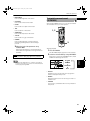
NOTES
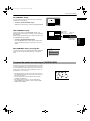
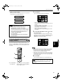
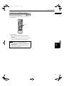
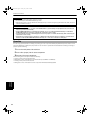
• Connect “Y” to “Y”, “PB” to “PB”, “PR” to “PR” correctly.
• When the component video input jacks of the TV is of the BNC type, use an adapter to convert a pin jack to a BNC jack
(optional).
• Make the “DOWN MIX” setting in “PREFERENCE 2” to “Lo/Ro” and the Speaker setting in “SPK. SETTING” to “2 CH.”
(see pages 60 and 62).
• When the Progressive scan mode is selected, the VIDEO and S-VIDEO outputs do not feed the correct signals.
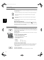
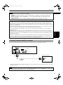
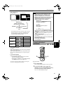
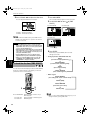
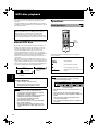
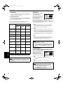
About SCAN MODE
To enjoy the progressive scanned video, a monitor (or TV or projector) to be connected to the unit must have the
Progressive inputs.
Depending on the material source format, DVD VIDEO discs can be classified into two types; film source and video
source (Note that some DVD VIDEO discs contain both film source and video source). Film sources are recorded as 24frame-per-second information, while (NTSC) video sources are recorded as 30-frame-per-second (60-field-per-second
interlaced) information.
When the unit plays back a film source material, uninterlaced progressive output signals are created using the original
information. When a video source material is played back, the unit interleaves lines between the interlaced lines on
each to create the pseudo uninterlaced picture and outputs as the progressive signal.
Getting started
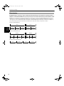
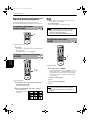
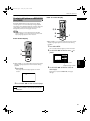
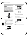
To display video on the monitor (television) screen, the conventional scanning method is called “Interlaced scan”.
With this method, only half of the horizontal lines are displayed at a time. So two fields complete a single picture
(frame); i.e., the first field, containing all the odd-numbered lines, is displayed followed by the second field, containing
all the even-numbered lines.
On the other hand, the Progressive scan system scans all horizontal lines at a time, so you can double the number of
pictures compared with the interlaced scan, resulting flicker-free, high-density picture.
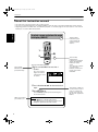
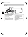
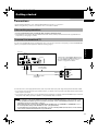
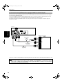
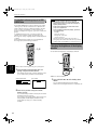
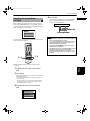
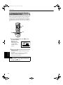
To connect to an audio amplifier or receiver
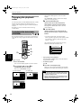
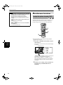
You can enjoy high-quality audio by connecting the unit's audio output to your amplifier or receiver.
The unit
AUDIO OUT
CENTER SUBWOOFER
DIGITAL OUT
PCM / STREAM
COAXIAL OPTICAL
VIDEO OUT
REAR
RIGHT LEFT
AV COMPU LINK
VIDEO
FRONT
RIGHT LEFT
Y
COMPONENT
PB
PR
S-VIDEO
Red
Amplifier or receiver
White
White
IN
LEFT
AUDIO
RIGHT
Audio cable
(supplied)
Red
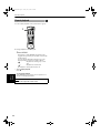
• Connect the unit's AUDIO OUT (FRONT LEFT/RIGHT) to any line-level inputs (such as AUX, DVD, CD, etc.) of an audio
amplifier or receiver.
NOTE
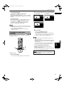
• When using the unit with a stereo amplifier or receiver, make the “DOWN MIX” setting in “PREFERENCE 2” to “Lo/Ro” and the
Speaker setting in “SPK. SETTING” to “2 CH.” (see pages 60 and 62).
19