1
E6581830
TOSVERT VF-S15 series
®
option unit Function Manual
CCL003Z
NOTICE
1. Read this manual before installing or operating. Keep this instruction manual on
hand of the end user, and make use of this manual in maintenance and inspection.
2. All information contained in this manual will be changed without notice. Please
contact your Toshiba distributor to confirm the latest information.
E658130
Introduction
Thank you for purchasing the “CC-Link® option (CCL003Z)” for TOSVERT VF-S15 drive.
This option can connect with open field network CC-Link and data communications with
the CC-Link master through installing this option in the VF-S15 and using it. Besides this
instruction manual, the “CC-Link option Instruction Manual” is required to develop
software communicating with VF-S15.
This option needs the option adaptor to connect VF-S15 which type form is SBP009Z.
Please match here and buy it when SBP009Z is not at hand yet.
After reading this function manual, please keep it handy for future reference.
For details of its general handling, see an instruction manual attached with the option
unit.
- TOSVERT VF-S15 Instruction Manual ·························································· E6581611
- TOSVERT VF-MB1/S15 communication option Precautions Manual ··········· E6581739
- TOSVERT VF-S15 Communication Function Instruction Manual ················· E6581913
CC-Link® is a registered trademark of Mitsubishi Electric Corporation.
-1-
E658130
Handling in general
Warning
Prohibited
Do not connect or disconnect a network cable while the drive power is on.
It may lead to electric shocks or fire.
Mandatory
See the instruction manual attached with the option unit for cautions the handling.
Otherwise, it may lead to electric shocks, fire, injuries or damage to product.
Network control
Warning
Prohibited
Do not send the value out of the valid range to objects and attributes.
Otherwise, the motor may suddenly start/stop and that may result in injuries.
Mandatory
Use an additional safety device with your system to prevent a serious accident due to the
network malfunctions. Usage without an additional safety device may cause an accident.
Caution
Mandatory
Set up “Communication error trip function (see below)” to stop the drive when the option
unit is deactivated by an unusual event such as tripping, an operating error, power
outage, failure, etc.
- Network Time-Out, drive operation at disconnection, Preset speed operation
selection
(Refer to 5.2 for details)
Deactivated the option module may cause an accident, if the “Communication error trip
function” is not properly set up.
Make sure that the operation signals are STOP before resetting drive’s fault. The motor
may suddenly start and that may result in injuries.
Notes on operation
Notes
When the control power is shut off by the instantaneous power failure, communication
will be unavailable for a while.
The Life of EEPROM is approximately 100,000 times. Avoid writing a command more
than 100,000 times to the same parameter of the drive and the option module.
-2-
E658130
Table of Contents
1.
2.
OVERVIEW ............................................................................................................................................ - 4 BASIC SPECIFICATIONS ..................................................................................................................... - 4 2.1. CC-Link Version .............................................................................................................................. - 5 2.1.1. CC-Link Ver. 1.10 .................................................................................................................... - 5 2.1.2. CC-Link Ver. 2 ......................................................................................................................... - 5 3. NAMES AND FUNCTIONS ................................................................................................................... - 6 3.1. Outline ............................................................................................................................................. - 6 4. INSTALLATION ON INVERTER ........................................................................................................... - 7 4.1. Connection cable ............................................................................................................................ - 7 4.2. Terminating resistor ........................................................................................................................ - 7 4.3. Connection of CC-Link master unit and inverter............................................................................. - 8 4.4. The maximum connection number of units ..................................................................................... - 9 4.5. LED indicator................................................................................................................................. - 11 5. FUNCTIONS ........................................................................................................................................ - 12 5.1. Initial setting .................................................................................................................................. - 12 5.2. Communication parameters for CCL003Z .................................................................................... - 13 5.3. CC-Link function setting ................................................................................................................ - 14 5.3.1. Station number setting ........................................................................................................... - 14 5.3.2. Baud rate setting.................................................................................................................... - 14 5.3.3. CC-Link extended setting ...................................................................................................... - 15 5.4. Basic functions .............................................................................................................................. - 16 5.4.1. Run and frequency operation command ............................................................................... - 16 5.4.2. Monitor ................................................................................................................................... - 16 5.4.3. Writing and reading the parameter ........................................................................................ - 16 5.5. I/O signal list.................................................................................................................................. - 17 5.5.1. One station is occupied (CC-Link Ver.1) (c122=0)........................................................... - 17 5.5.2. Double setting is selected (CC-Link Ver.2) (c122=1) ....................................................... - 18 5.5.3. Quadruple setting is selected (CC-Link Ver.2) (c122=2).................................................. - 18 5.5.4. Octuple setting is selected (CC-Link Ver.2) (c122=3) ...................................................... - 19 5.5.5. Faults history.......................................................................................................................... - 20 5.5.6. Detail of input and output signals........................................................................................... - 21 5.5.7. Remote Register Assignment ................................................................................................ - 24 5.5.8. Instruction Codes ................................................................................................................... - 28 5.5.9. The details of an error code................................................................................................... - 30 5.5.10.
Description of reply code.................................................................................................... - 32 5.5.11.
Description of monitor code ............................................................................................... - 33 5.5.12.
Description of input terminal information............................................................................ - 34 5.5.13.
Description of output terminal information ......................................................................... - 34 6. PROGRAMMING EXAMPLES ............................................................................................................ - 35 6.1. Program example for reading the inverter status.......................................................................... - 38 6.2. Program example for setting the operation mode......................................................................... - 39 6.3. Program example for setting the operation commands ................................................................ - 40 6.4. Program example for setting the running frequency..................................................................... - 40 6.5. Program example for monitoring the output frequency................................................................. - 41 6.6. Program example for parameter writing........................................................................................ - 42 6.7. Program example for parameter reading ...................................................................................... - 43 6.8. Program example for fault record reading .................................................................................... - 44 6.9. Program example for resetting the inverter at inverter error......................................................... - 45 6.10.
Instructions ................................................................................................................................ - 46 7. UNUSUAL DIAGNOSIS....................................................................................................................... - 47 7.1. Option error ................................................................................................................................... - 47 7.2. Disconnection error of network cable ........................................................................................... - 47 7.3. How to check the error using the LEDs ........................................................................................ - 48 -
-3-
E658130
1. Overview
The option allows the VF-S15 drive to be connected into a CC-Link network. CC-Link supports a
maximum of 42 nodes, allowing for the Master and this option is based on CC-Link V1.1 and V2.0.
The CCL-003Z is able to operate RUN/STOP, monitor the status of the drive, set the drive’s parameter
and etc. by the CC-Link master through installing the VF-S15. And it can use various applications.
2. Basic specifications
<Environmental specification>
Item
Specification
Operating
environment
Indoors, an altitude of 3,000m or less, where the product will not be exposed
to direct sunlight, corrosive or explosive gasses, vapor, coarse particulates
including dust and where there is no grinding fluid or grinding oil nearby.
Ambient
temperature
0 to + 60 degreeC
Storage
temperature
-25 to +65 degreeC
Related
temperature
20 to 93% (no condensation and absence of vapor)
Vibration
5.9 m/s2 (0.6G) or less (10 – 55Hz)
<CC-Link communication and option specification>
Item
Number of
corrected
Specification
units
42 units max. (1 station occupied by 1 unit). May be used with other
equipment.
Baud rate
156k, 625k, 2.5M, 5M, 10Mbps
Power supply
Supplied from SBP009Z
Station type
Remote device station
Number of stations
occupied
Ver.1: occupies one station, V2: occupies one station (selectable from among
double, quadruple and octuple)
Connect cable
CC-Link dedicated cable,
CC-Link V1.10 compatible CC-Link dedicated cable
-4-
E658130
2.1. CC-Link Version
2.1.1.
CC-Link Ver. 1.10
The conventional CC-Link products, whose inter-station cable lengths have equally been
changed to 20cm (7.87 inch) or more to improve the inter-station cable length restriction,
are defined as CC-Link Ver. 1.10. In comparison the conventional products are defined
as CC-link Ver. 1.00.
Refer to the CC-link Master Module Manual for the maximum overall cable lengths and
inter-station cable lengths of CC-Link Ver. 1.00 and Ver. 1.10
CC-Link Ver. 1.10 compatibility conditions
1) All modules that comprise a CC-Link system should be compatible with CC-Link Ver.
1.10.
2) All data link cables should be CC-Link Ver. 1.10 compatible, CC-Link dedicated cables.
(CC-Link Ver.1.10 compatible cables have a logo or Ver. 1.10 indication.)
*In a system that uses the CC-Link Ver. 1.00 and Ver. 1.10 modules and cables together,
the maximum overall cable length and inter-station cable length are as specified for
CC-Link Ver. 1.00.
2.1.2.
CC-Link Ver. 2
The CCL003Z is compatible with CC-Link Ver.2.
When using the CC-Link Ver.2 setting with the CCL003Z, the master station needs to be
compatible with the CC-Link Ver.2.
For CC-Link Ver.2, double, quadruple and octuple settings can be used to increase
remote register (RWw/r) point.
-5-
E658130
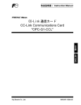
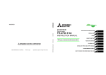
3. Names and functions
The drawing below shows names and functions of main parts.
3.1. Outline
Connector to the inverter
Release tab
LED indicator
(See 4.5)
CC-Link Connector
DA
-6-
DB
DG
SLD
FG
E658130
4. Installation on inverter
Refer to VF-S15 option adapter instruction manual (E6581838) for the installation on the
inverter.
Mandatory
The following steps must be performed before installing.
1. Shut off all input power.
2. Wait at least 15 minutes and check to make sure that the charge lamp is no longer lit.
4.1. Connection cable
In the CC-Link system, use CC-Link dedicated cables.
If the cable used is other than the CC-Link dedicated cable, the performance of the
CC-Link system is not guaranteed.
For the specifications of the CC-Link dedicated cable, refer to the website of the CC-Link
Partner Association.
Website: http://www.cc-link.org/
Strip off the sheath of the CC-Link dedicated cable and wind wires to use. If the length of
the sheath pealed is too long, a short circuit may occur among neighboring wires. If the
length is too short, wires might come off.
・Recommended screwdriver:Small flat-blade screwdriver
(Tip thickness: 0.4mm /tip width: 2.5mm)
・Recommented tightening Torque:0.22N・m to 0.25N・m
・Cable stripping size:About 7mm
7mm
*Fix a cable so that a communication connector may be not taken the weight of wire.
When the cable is not connected easily, the use of the following bar terminal is
recommended.
Phoenix Contact Co. Ltd.
Bar terminal model: AI-TWIN2x0,5-8 WH
Length of bar terminal: 8mm
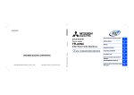
4.2. Terminating resistor
Connect the terminating resistor of 110Ω or 130Ω (CC-Link Ver.1.00 dedicated high
performance cable.) between terminals at the end.
-7-
E658130
4.3. Connection of CC-Link master unit and inverter
The example of the connection of the CC-Link master unit and the inverter is shown.。
Motor
U/T1
R/L1
CC-Link
Master
Unit
DA
DA
DB
DB
DG
DG
SLD
SLD
FG
FG
S/L2
Inverter
V/T2
T/L3
VF-S15
W/T3
IM
CCL003Z
*Connection of Several Inverters
Factory Automation can be applied to several inverters which share a link system as
CC-Link remote device stations and are controlled and monitored by PLC user programs.
◎ DA,DB
Shield twisted cable
◎ DG
◎ SLD / FG
Connect the shielded wire of the dedicated CC-Link cable to the “SLD” of each
module, and ground both ends of the shielded wire using type-D grounding (class 3
grounding) via “FG.”
(The ground resistance is 100Ω or less.)
◎ Terminal resistor
Connect the terminal resistor of 110Ω.
(130Ω is a resistance value for the CC-Link Ver.1.00 dedicated high performance cable.)
Terminal
Inverter
DA
Inverter
DB
DB
DB
DG
DG
DG
Mater unit
DA
resistor
110Ω 1/2W
(130Ω 1/2W)
SLD
FG
Shie ld twisted cable
SLD
FG
-8-
DA
S hield twisted cable
SLD
FG
Terminal
resistor
110Ω 1/2W
(130Ω 1/2W)
E658130
4.4.
The maximum connection number of units
1. Maximum number of units connected to one master station (CC-Link Ver.1.10)
42 units (when only inverters are connected)
If any other units are included, the number of stations occupied depends on the unit and
therefore the following conditions must be satisfied:
{(1 × a) + (2 × b) + (3 × c) + (4 × d)} ≦ 64
a: Number of units occupying 1 station
b: Number of units occupying 2 stations
c: Number of units occupying 3 stations
d: Number of units occupying 4 stations
{(16 × A) + (54 × B) + (88 × C)} ≦ 2304
A: Number of remote I/O stations ≦ 64
B: Number of remote device stations ≦ 42
C: Number of local, standby master and intelligent device stations ≦ 26
-9-
E658130
2. Maximum number of units connected to one master station (CC-Link Ver.2.00)
42 units (when connections are inverter only)
If any other units are included, the number of stations occupied depends on the unit and
therefore the following conditions must be satisfied:
{(a + a2 + a4 + a8) + (b + b2 + b4 + b8) × 2 + (c + c2 + c4 + c8) × 3
+ (d + d2 + d4 + d8) × 4} ≦ 64
{(a × 32 + a2 × 32 + a4 × 64 + a8 × 128) + (b × 64 + b2 × 96 + b4 × 192 + b8 × 384)
+ (c × 96 + c2 × 160 + c4 × 320 + c8 × 640) + (d × 128 + d2 × 224 + d4 × 448 + d8 × 896)}
≦ 8192
{(a × 4 + a2 × 8 + a4 × 16 + a8 × 32) + (b × 8 + b2 × 16 + b4 × 32 + b8 × 64)
+ (c × 12 + c2 × 24 + c4 × 48 + c8 × 96) + (d × 16 + d2 × 32 + d4 × 64 + d8 × 128)} ≦
2048
a: Number of single setting devices occupying one station
b: Number of single setting devices occupying two stations
c: Number of single setting devices occupying three stations
d: Number of single setting devices occupying four stations
a2: Number of double setting devices occupying one station
b2: Number of double setting devices occupying two stations
c2: Number of double setting devices occupying three stations
d2: Number of double setting devices occupying four stations
a4: Number of quadruple setting devices occupying one station
b4: Number of quadruple setting devices occupying two stations
c4: Number of quadruple setting devices occupying three stations
d4: Number of quadruple setting devices occupying four stations
a8: Number of octuple setting devices occupying one station
b8: Number of octuple setting devices occupying two stations
c8: Number of octuple setting devices occupying three stations
d8: Number of octuple setting devices occupying four stations
16 × A + 54 × B + 88 × C ≦ 2304
A: Numbers of remote I/O ≦ 64
B: Number of remote device stations ≦ 42
C: Number of local and intelligent device stations ≦ 26
- 10 -
E658130
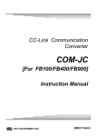
4.5.
LED indicator
The LEDs shows the present status of the network and module
Refer to 7.3 for detail.
L.RUN
SD
L.ERR
RD
■ Layout of LED
L.RUN
Light on during communication.
SD
Light on during send the data of CC-Link.
RD
Light on during receive the data of CC-Link.
L.ERR
Light on during communication error.
- 11 -
E658130
5.
Functions
This option is a communication interface unit that allows the PLC program to operate, monitor
and set the parameter of the inverter as a remote station of CC-Link. It is able to communicate
with a maximum speed of 10Mbps not only transmitting bit data but also by word data.
Moreover, more data transmissions are possible by the use of CC-Link V2.0.
5.1. Initial setting
Set the following parameters of the inverter.
Title
cmod
fmod
Function
Command mode
selection
Frequency
setting
mode selection 1
Description
0: Terminal board
1: Panel keypad (including remote keypad)
2: RS485 communication
3: CANopen communication
4: Communcation option
0: Setting dial 1 (save even if power is off)
1: Terminal board VIA
2: Terminal board VIB
3: Setting dial 2 (press in center to save)
4: RS485 communication
5: UP/DOWN from external logic input
6: CANopen communication
7: Communication option
8: Terminal board VIC
9, 10: 11: Pulse train input
Factory
setting
CC-Link
setting
1
4
0
7
2
*
0
-
12, 13: 14: sro
f856
Number of motor
pole for
communication
f899
Communication
function reset
1: 2 poles
2: 4 poles
3: 6 poles
4: 8 poles
5: 10 poles
6: 12 poles
7: 14 poles
8: 16 poles
0: 1: Reset (after execution: 0)
*Set parameter according to number of motor pole used.
- 12 -
E658130
5.2.
Communication parameters for CCL003Z
Title
c100
Function
Communication error detection
delay time
c101
Inverter operation at the
communication loss action
c102
c103
c120*
Preset speed
operation selection
Communication time-out
condition selection
CC-Link station number
selection
Description
0.0 - 100.0 sec.
0: Stop and controlled by cmod, fmod
1: Operation continue
2: Deceleration stop
3: Coast stop
4: Network error stop (err8 trip)
5: Preset speed operation (by c102 setting)
0: None
1 to 15: Preset speed
0: Disconnection detection
1: When communication mode enable (Both cmod and
fmod are set CANopen or communication option) only
2: 1 + Driving operation
1 to 64
Set the number of stations of inverters (Remote device
station).
c121*
CC-Link baud rate selection
0: 156kbps
1: 625kbps
2: 2.5Mbps
3: 5Mbps
4: 10Mbps
Set the baud rate for CC-LINK network
c122*
CC-Link extended selection
0: Occupies one station (V1.10)
1: Occupies one station double (V2.0)
2: Occupies one station quadruple (V2.0)
3: Occupies one station octuple (V2.0)
The function of remote registers can be enhanced.
* Set parameters according to the CC-Link network system.
- 13 -
E658130
5.3.
CC-Link function setting
5.3.1. Station number setting
Use parameter c120 to set station number of the inverter.
Set this parameter within the range of 1 to 64.
Title
c120
Function
Description
CC-Link station
number selection
1 to 64
*Use different station numbers for different devices. (If different devices have the same station
number, the communication cannot be performed properly.)
・ Set consecutive numbers for the station numbers. (Do not skip a number in sequence
like "station number 1 - station number 2 - station number 4".)
・The station number does not have to match with the physical connection sequence.
(There is no problem with having the physical connection sequence like "station
number 1 - station number 3 - station number 4 - station number 2".)
・ One inverter occupies one station. (One remote device station)
・ "L.ERR" LED flickers if the setting is changed. When power is switched on again,
reset by parameter (f899 = 1) or the RES signal is turned on, the setting value is
reflected and the LED turns off.
5.3.2. Baud rate setting
Set the transmission speed. (Refer to the manual for the CC-Link master module for
details of transmission speed.)
Title
Function
c121
CC-Link baud rate selection
Description
0: 156kbps
1: 625kbps
2: 2.5Mbps
3: 5Mbps
4: 10Mbps
・ "L.ERR" LED flickers if the setting is changed. When power is switched on again,
reset by parameter (f899 = 1) or the RES signal is turned on, the setting value is
reflected and the LED turns off.
- 14 -
E658130
5.3.3. CC-Link extended setting
Remote register function can be extended.
Title
Function
c122*
CC-Link extended selection
Description
0: Occupies one station (V1.10)
1: Occupies one station double (V2.0)
2: Occupies one station quadruple (V2.0)
3: Occupies one station octuple (V2.0)
・ When using double, quadruple and octuple settings of the CC-Link Ver.2, station data
of the master station must be set to double, quadruple and octuple also.
(If the master station is CC-Link Ver.1 compatible station, the above setting can not be
made.)
- 15 -
E658130
5.4.
Basic functions
This clause shows the basic function of this CC-Link option using by CC-Link communication.
5.4.1. Run and frequency operation command
The PLC program can operate the inverter to run, stop, set the operation frequency and
change the parameters.
If the PLC controls these operations, select the command mode and the frequency setting
mode.
The parameter setting of the inverter
Command mode selection
cmod
: 4[Communication option] (Factory setting: 1)
Frequency setting mode selection
fmod
: 7[Communication option] (Factory setting: 0)
* The frequency setting and command can be made CC-Link priority by RYnA and RYnB.
("n" is depend on the station number.)
5.4.2. Monitor
It is able to monitor the status of the inverter.
Set a monitor code to RWw n and turn RYnC on.
The data is stored in the buffer memory of the PLC.
* "n" is depend on the station number.
The monitor value is updated while RynC has been turned on.
Refer to 5.5.11 for detail.
5.4.3. Writing and reading the parameter
The PLC can read, write the inverter parameters and reset the inverter.
Set the command code to RWw(n+2) (set the write data to RWw(n+3) if necessary) and
turn RYnF (instruction code execution request) on.
The inverter performs processing corresponding to the command code, return the response
data, read out data and RXnF (instruction code execution completion).
▪ Refer to 5.5.8 for detail.
- 16 -
E658130
5.5.
I/O signal list
5.5.1. One station is occupied (CC-Link Ver.1) (c122=0)
This option occupies one station area of the buffer memory of the PLC.
In the case of c122 = 0, there are remote I/O (RX, RY both 32 bits) and the remote register
(RWw, RWr both 4 word) in the communication data for one station area.
Remote I/O (Default value = 0)
Inverter (Slave) → PLC (Master)
Device No.
Signal
RXn0
Forward running
RXn1
Reverse running
RXn2
Output terminal 1 (RY-RC)
RXn3
Output terminal 2 (OUT)
RXn4
Output terminal 3 (FL)
RXn5
Failure FL
RXn6
PI control OFF
Acceleration/deceleration
RXn7
pattern selection (1 or 2)
RXn8
Emergency stop
PLC (Master) → Inverter (Slave)
Device No.
Signal
RYn0
Forward rotation command
RYn1
Reverse rotation command
RYn2
Input terminal 3 (S1)
RYn3
Input terminal 4 (S2)
RYn4
Input terminal 5 (S3)
RYn5
Input terminal 6 (S4)
RYn6
Input terminal 7 (PIOFF)
RYn7
Input terminal 8 (AD1)
RYn8
RYnE
Input terminal 9 (ESTP)
Intercept output to inverter
(Coast stop)
Frequency priority CC-Link
Command priority CC-Link
Monitor command
Frequency setting command
(RAM)
Reserved**
RYnF
Instruction code execution request
RXn9
Coast stop (ST = OFF)
RYn9
RXnA
RXnB
RXnC
Alarm
Reserved*
Monitoring
Frequency setting completion
(RAM)
Reserved*
Instruction code execution
completion
RYnA
RYnB
RYnC
RXnD
RXnE
RXnF
RYnD
RX(n+1)0
to
RX(n+1)9
Reserved*
RY(n+1)0
to
RY(n+1)9
RX(n+1)A
Error status flag
RY(n+1)A
Reserved**
Error reset request flag
(A reset request is during switched
ON)
Reserved**
RX(n+1)B
Remote station ready
RY(n+1)B
RX(n+1)C
RY(n+1)C
to
Reserved*
to
Reserved**
RX(n+1)F
RY(n+1)F
"n" is depend on the station number.
* The bit described " Reserved " is unstable. Don't use the “Reserved " bit for the judgment.
** Set OFF (“0”) to reserved bit.
Remote register (Default value = 0)
RWr
Inverter → PLC
Address
Signal
RWr n
Monitor value 1
Monitor value 2
RWr n+1
(output frequency)
RWr n+2
Reply code
RWr n+3
Read data
"n" is depend on the station number.
RWw
- 17 -
Address
RWw n
RWw n+1
PLC → Inverter
Signal
Monitor code (1 and 2)
Set frequency
RWw n+2
RWw n+3
Instruction code
Write data
E658130
5.5.2. Double setting is selected (CC-Link Ver.2) (c122=1)
This option occupies one station area of the buffer memory of the PLC.
In the case of c122 = 1, there are remote I/O (RX, RY both 32 bits(same as CC-LINK
Ver.1)) and the remote register (RWw, RWr both 8 word) in the communication data for one
station area.
* Default value of RY and RX is 0.
Remote register (Default value = 0)
RWr
Inverter → PLC
Address
Signal
RWr n
Monitor value 1
Monitor value 2
RWr n+1
(output frequency)
RWr n+2
Reply code
RWr n+3
Read data
RWr n+4
Monitor value 3
RWr n+5
Monitor value 4
RWr n+6
Monitor value 5
RWr n+7
Monitor value 6
"n" is depend on the station number.
RWw
Address
RWw n
RWw n+1
PLC → Inverter
Signal
Monitor code (1 and 2)
Set frequency
RWw n+2
RWw n+3
RWw n+4
RWw n+5
RWw n+6
RWw n+7
Instruction code
Write data
Monitor code 3
Monitor code 4
Monitor code 5
Monitor code 6
5.5.3. Quadruple setting is selected (CC-Link Ver.2) (c122=2)
This option occupies one station area of the buffer memory of the PLC.
In the case of c122 = 2, there are remote I/O (RX, RY both 32 bits(same as CC-LINK
Ver.1)) and the remote register (RWw, RWr both 16 word) in the communication data for one
station area.
* Default value of RY and RX is 0.
Remote register (Default value = 0)
RWr
Inverter → PLC
RWw
PLC → Inverter
Address
Signal
Address
Signal
RWr n
Monitor value 1
RWw n
Monitor code (1 and 2)
Monitor value 2
RWw n+1
Set frequency
RWr n+1
(output frequency)
RWr n+2
Reply code
RWw n+2
Instruction code
RWr n+3
Read data
RWw n+3
Write data
RWr n+4
Monitor value 3
RWw n+4
Monitor code 3
RWr n+5
Monitor value 4
RWw n+5
Monitor code 4
RWr n+6
Monitor value 5
RWw n+6
Monitor code 5
RWr n+7
Monitor value 6
RWw n+7
Monitor code 6
Upper 8
Upper 8
Trip history No.
Trip history No.
Bits
Bits
RWr n+8
RWw n+8
Lower 8
Lower 8
Trip code
Reserved**
Bits
Bits
RWr n+9
Trip information (output frequency)
RWw n+9
Reserved**
RWr n+A
Trip information (output current)
RWw n+A
Reserved**
RWr n+B
Trip information (output voltage)
RWw n+B
Reserved**
RWr n+C
Trip information (energization time)
RWw n+C
Reserved**
RWr n+D
Reserved*
RWw n+D
Reserved**
RWr n+E
Reserved*
RWw n+E
Reserved**
RWr n+F
Reserved*
RWw n+F
Reserved**
"n" is depend on the station number.
* The bit described " Reserved " is unstable. Don't use the “Reserved " bit for the judgment.
** Do not use it.
- 18 -
E658130
5.5.4. Octuple setting is selected (CC-Link Ver.2) (c122=3)
This option occupies one station area of the buffer memory of the PLC.
In the case of c122 = 3, there are remote I/O (RX, RY both 32 bits(same as CC-LINK
Ver.1)) and the remote register (RWw, RWr both 32 word) in the communication data for one
station area.
* Default value of RY and RX is 0.
Remote register (Default value = 0)
RWr
Inverter → PLC
RWw
PLC → Inverter
Address
Signal
Address
Signal
RWr n
Monitor value 1
RWw n
Monitor code (1 and 2)
Monitor value 2
RWw n+1
Set frequency
RWr n+1
(output frequency)
RWr n+2
Reply code
RWw n+2
Instruction code
RWr n+3
Read data
RWw n+3
Write data
RWr n+4
Monitor value 3
RWw n+4
Monitor code 3
RWr n+5
Monitor value 4
RWw n+5
Monitor code 4
RWr n+6
Monitor value 5
RWw n+6
Monitor code 5
RWr n+7
Monitor value 6
RWw n+7
Monitor code 6
Upper 8
Upper 8
Trip history No.
Trip history No..
Bits
Bits
RWr n+8
RWw n+8
Lower 8
Lower 8
Trip code
Reserved**
Bits
Bits
RWr n+9
Trip information (output frequency)
RWw n+9
Reserved**
RWr n+A
Trip information (output current)
RWw n+A
Reserved**
RWr n+B
Trip information (output voltage)
RWw n+B
Reserved**
RWr n+C
Trip information (energization time)
RWw n+C
Reserved**
RWr n+D
Reserved*
RWw n+D
Reserved**
RWr n+E
Reserved*
RWw n+E
Reserved**
RWr n+F
Reserved*
RWw n+F
Reserved**
RWr n+10
Reply code 2
RWw n+10
Instruction code 2
RWr n+11
Read data 2
RWw n+11
Write data 2
RWr n+12
Reply code 3
RWw n+12
Instruction code 3
RWr n+13
Read data 3
RWw n+13
Write data 3
RWr n+14
Reply code 4
RWw n+14
Instruction code 4
RWr n+15
Read data 4
RWw n+15
Write data 4
RWr n+16
Reply code 5
RWw n+16
Instruction code 5
RWr n+17
Read data 5
RWw n+17
Write data 5
RWr n+18
Reply code 6
RWw n+18
Instruction code 6
RWr n+19
Read data 6
RWw n+19
Write data 6
RWr n+1A
Reserved*
RWw n+1A
Reserved**
RWr n+1B
Reserved*
RWw n+1B
Reserved**
RWr n+1C
Reserved*
RWw n+1C
Reserved**
RWr n+1D
Reserved*
RWw n+1D
Reserved**
RWr n+1E
Reserved*
RWw n+1E
Reserved**
RWr n+1F
Reserved*
RWw n+1F
Reserved**
"n" is depend on the station number.
* The bit described " Reserved " is unstable. Don't use the “Reserved " bit for the judgment.
** Do not use it.
- 19 -
E658130
5.5.5. Trip history
When “Quadruple setting” or “Octuple setting” of CC-LINK V.2 is selected, the past trip
information can be referred to by the following methods.
RWr n+8
RWr n+9
RWr n+A
RWr n+B
RWr n+C
Upper 8
Trip history No.
Bits
Lower 8
Trip code
Bits
Trip information (output frequency)
Trip information (output current)
Trip information (output voltage)
Trip information (energization time)
RWw n+8
RWw n+9
RWw n+A
RWw n+B
RWw n+C
Upper 8
Bits
Lower 8
Bits
Reserved
Reserved
Reserved
Reserved
1. Set the past trip history No. to upper 8 bits of "RWw n+8."
2. The following information is stored to registers.
Trip history No. : Upper 8 bits of "RWr n+8."
Trip code
: Lower 8 bits of "RWr n+8."
Output frequency : “RWr n+9”
Output current
: “RWr n+A”
Output voltage
: “RWr n+B”
Energization time : “RWr n+C”
- 20 -
Trip history No..
Reserved
E658130
5.5.6. Detail of input and output signals
1. Output signals (Master -> Inverter)
The output signals from the master unit are indicated. (Input signals to inverter)
Device No.
RYn0
RYn1
RYn2
RYn3
RYn4
RYn5
RYn6
RYn7
RYn8
RYnA
RYnB
Signal
Forward run command
Reverse run command
Input terminal function 3(S1)
Input terminal function 4(S2)
Input terminal function 5(S3)
Input terminal function 6(S4)
Input terminal function (PIOFF)
Input terminal function 8(AD1)
Input terminal function 9(ESTP)
Intercept output to inverter
(Coast stop)
Frequency priority CC-Link
Command priority CC-Link
RYnC
Monitor command
RYnD
Frequency setting command
(RAM)
RYnE
Reserved**
RYnF
Instruction code execution request
RYn9
RY(n+1)0
to Y(n+1)9
RY(n+1)A
Description
OFF: Stop command ON: Forward run command***
OFF: Stop command ON: Reverse run command***
The function depends on input terminal selection 3 (c142) *
The function depends on input terminal selection 4 (c143) *
The function depends on input terminal selection 5 (c144) *
The function depends on input terminal selection 6 (c145) *
The function depends on input terminal selection 7 (c146) *
The function depends on input terminal selection 8 (c147) *
The function depends on input terminal selection 9 (c148) *
Stop the output of the inverter when turned on this signal.
(Stop the output in the secondary circuit)
Speed commands are entered from the CC-Link.
Signals from the CC-Link are used to start and stop operation
When the monitor command (RYnC) is switched on, each
monitored values are set to remote registers RWrn, RWrn+1,
RWrn+4 to RWrn+7 and monitoring flag (RXnC) switches on.
While the monitor command (RYnC) is on, the monitored
value is always updated.
When the frequency setting command (RYnD) is switched
on, the set frequency RWwn+1 is written to the inverter.
After the writing completion, frequency setting completion flag
(RXnD) switches on.
When the frequency setting command (RYnD) is ON, the set
frequency is always updated.
Reserved**
When the instruction code execution request (RYnF) is
switched on, processes corresponding to the instruction codes
are set to RWwn+2, RWwn+10, RWwn+12, RWwn+14,
RWwn+16 and RWwn+18 are executed.
After completion of instruction code execution, instruction code
execution completion flag (RXnF) switches on.
When an instruction code execution error occurs, a value other
than 0 is set to the reply code (RWrn+2, RWrn+10, RWrn+12,
RWrn+14, RWrn+16 and RWrn+18)
The instruction code execution request is effective only when
this signal changes from OFF to ON.
Special monitor (72H) is chosen by the instruction code, and
this signal always updates a monitor value during ON.
Reserved**
Reserved**
Error reset request
If the error reset request (RY(n+1)A) is switched on only
when an inverter fault occurs, the inverter is reset and the
error status flag (RX(n+1)A) switches off.
RY(n+1)B
Reserved**
Reserved**
to RY(n+1)F
"n" is depend on the station number.
* The input terminal function can be changed by the input terminal function selections(c142 to c148).
(But there are functional restrictions. Refer to the following page.)
** Set OFF (“0”) to reserved bit.
***When RYn0 and RYn1 are ON simultaneously, the rotation is followed a parameter f105(default = stop).
- 21 -
E658130
■Input function selection from the CC-Link.
The function numbers selection of the RYn2 to RYn8 function valid from the command of the CC-Link are following
boldface numbers.
Positive logic Negative logic
0
1
2
3
4
5
6
7
8
9
10
11
12
13
14
15
16
17
18
19
20
21
22
23
24
25
26
27
28
29
32
33
36
37
46
47
48
49
50
51
52
53
54
55
56
57
58
59
60
61
62
63
64
65
74
75
76
77
Function
Speed control
No function is assigned
●/●
Forward run command
●/●
Reverse run command
●/●
Standby
●/●
Reset command
●/●
Preset speed command 1
●/●
Preset speed command 2
●/●
Preset speed command 3
●/●
Preset speed command 4
●/●
Jog run mode
●/●
Emergency stop by external signal *
●/●
DC braking command
●/●
2nd acceleration/deceleration
●/●
3rd acceleration/deceleration
●/●
2nd V/F control mode switching
●/●
2nd stall prevention level
●/●
PID control prohibition
●/●
External thermal error input
●/●
Forced local from communication
●/●
Operation hold (hold of 3-wire operation)
●/●
PID integral/differential clear
●/●
PID characteristics switching
●/●
Forced run operation
●/●
Fire speed operation
●/●
Acceleration/deceleration suspend signal
●/●
Power failure synchronized signal
●/●
My function-S trigger signal
●/●
Integrating wattmeter(kWh) display clear
●/●
Trace back trigger signal
●/●
Light-load high-speed operation
78
79
●/●
prohibitive signal
80
81
Holding of RY-RC terminal output
●/●
82
83
Holding of OUT terminal output
●/●
88
89
Frequency UP
●/●
90
91
Frequency DOWN
●/●
92
93
Clear frequency UP/DOWN
●/●
96
97
Coast stop command
●/●
98
99
Forward/reverse selection
●/●
100
101
Run/Stop command
●/●
104
105
Frequency setting mode forced switching
●/●
106
107
Frequency setting mode terminal block
●/●
108
109
Command mode terminal block
●/●
110
111
Parameter editing permission
●/●
120
121
Fast stop command 1
●/●
122
123
Fast stop command 2
●/●
134
135
Traverse permission signal
●/●
136
137
Low voltage operation signal
●/●
140
141
Forward deceleration
●/●
142
143
Forward stop
●/●
144
145
Reverse deceleration
●/●
146
147
Reverse stop
●/●
No.2 motor switching
152
153
●/●
(AD2 + VF2 + OCS2)
200
201
Parameter editing prohibition
●/●
202
203
Parameter reading prohibition
●/●
* This function is not dependent on cmod.
- 22 -
PM control
●
●
●
●
●
●
●
●
●
●
●
●
●
●
●
●
●
●
●
●
●
●
●
●
●
●
●
●
●
V/f
●
●
●
●
●
●
●
●
●
●
●
●
●
●
●
●
●
●
●
●
●
●
●
●
●
●
●
●
●
●
●
●
●
●
●
●
●
●
●
●
●
●
●
●
●
●
●
●
●
●
●
●
●
●
●
●
●
●
●
●
●
●
●
●
●
●
●
●
●
●
●
●
●
●
●
●
●
E658130
2. Input signal (Inverter -> Master)
The following shows input signals to the master unit. (The output signals for the inverter.)
Device No..
Signal
RXn0
Forward running
RXn1
Reverse running
RXn2
Output terminal function 1
(RY-RC)
RXn3
Output terminal function 2 (OUT)
RXn4
Output terminal function 3 (FL)
RXn5
Failure FL
RXn6
PI control OFF
RXn8
Acceleration/ deceleration
pattern selection (1 or 2)
Emergency stop
RXn9
Coast stop (ST = OFF)
RXnA
Alarm
RXnB
Reserved*
RXnC
Monitoring flag
RXnD
Frequency setting completion flag
(RAM)
RXnE
Reserved*
RXnF
Instruction code execution
completion flag
RXn7
RX(n+1)0
to RX(n+1)9
Reserved*
RX(n+1)A
Error status flag
RX(n+1)B
Remote station ready
Description
OFF: Other than forward running
(during stop or reverse rotation)
ON : Forward running
OFF: Other than reverse running
(during stop or forward rotation)
ON : Reverse running
The function depends on output terminal function selection 1
(f130).
The function depends on output terminal function selection 2
(f131).
The function depends on output terminal function selection 3
(f132).
OFF : No failure
ON : Failure
OFF : PI control permitted
ON : PI control prohibited
OFF: Acceleration/deceleration pattern 1 (AD1)
ON : Acceleration/deceleration pattern 2 (AD2)
ON : Emergency stop
OFF : ST = ON
ON : ST = OFF
OFF: No alarm
ON : Alarm issued
Reserved*
Switched on when the monitored values are set to RWrn,
RWrn+1, RWrn+4 to RWrn+7 by the monitor command
(RYnC) switching on. Switched off when the monitor
command (RYnC) is switched off.
Switched on when the set frequency is written to the inverter
by the frequency setting command (RYnD) switching on.
Switched off when the frequency setting command (RYnD)
is switched off.
Reserved*
Switched on completion of the processing corresponding to
the instruction code (RWw+2) which is executed when the
instruction code execution request (RYnF) switches on.
Switched off when the instruction code execution completion
flag (RXnF) is switched off.
Reserved*
Switched on when occurred an inverter error or option error
(watchdog error, CPU error, ROM error or RAM error).
It is not switched on besides that.
Switched on when the inverter goes into the ready status on
completion of initial setting after power-on or hardware reset.
(Used as an interlock for read/write from/to the master.)
Switched off when an inverter error occurs (protective
function is activated).
RX(n+1)C
Reserved*
Reserved*
to RX(n+1)F
"n" is depend on the station number.
* The bit described " Reserved " is unstable. Don't use the “Reserved " bit for the judgment.
- 23 -
E658130
5.5.7. Remote Register Assignment
Divide the monitor code (RWw n) into half and select the monitor value 1 (RWr n) from the
lower 8 bits and the monitor value 2 (RWr n) from the higher 8 bits.
For example: When output voltage is selected for the monitor value 1 and output torque is
selected for the monitor value 2. -> The monitor code is 0703H.
* The hexadecimal value attaches and expresses "H" to the end of a number.
1. Remote register (Master -> inverter)
RWw
Address
Signal
Description
Set the monitor code to be referenced. By switching on the (RYnC) signal
after setting, the specified monitored data is set to (RWr n).
RWw n
Monitor code
(1 and 2)
The monitor value 1 (RWr n): RWw n Setting of the lower 8 bits of monitor
code.
The monitor value 2 (RWr n+1): RWw n Setting of the upper 8 bits of
monitor code.
Set the set frequency. After setting the register, a frequency is written
RWwn+1
Set frequency
after turning on (RynD). When the writing of the frequency is completed,
(RXnD) turns on, depending on the input command.
Unit: 0.01Hz
Set the command code for actions such as operation mode switching,
RWwn+2
Command code 1
parameter read, write, error reference, error clear, etc. The command will
be executed by turning (RynF) on after the register setting is completed.
When the command execution is completed, (RXnF) turns on.
Set data specified by the above-mentioned command code
(if necessary).
RWwn+3
Write data 1
If no data needs to be written, the value shall be zero.
(RynF) is turned on after setting the above-mentioned command code
and this register.
RWwn+4
Monitor code 3
RWwn+5
Monitor code 4
RWwn+6
Monitor code 5
RWwn+7
Monitor code 6
Set the monitor code to be monitored. By setting "ON” in (RYC) after
setting, the specified monitored data is stored in RWr n+4.
Set the monitor code to be monitored. By setting "ON” in (RYC) after
setting, the specified monitored data is stored in RWr n+5.
Set the monitor code to be monitored. By setting "ON” in (RYC) after
setting, the specified monitored data is stored in RWr n+6.
Set the monitor code to be monitored. By setting "ON” in (RYC) after
setting, the specified monitored data is stored in RWr n+7.
Set how many fault records in past to be read.
RWwn+8
Trip history No.
Upper 8 bits: H00 (latest fault) to H07 (eight faults in past)
Lower 8 bits: H00
RWwn+9
to
Reserved
Reserved
RWwn+F
- 24 -
E658130
Address
Signal
Description
Set the command code for actions such as operation mode switching,
RWwn+10
Instruction code 2
parameter read, write, error reference, error clear, etc. The command will
be executed by turning (RynF) on after the register setting is completed.
When the command execution is completed, (RXnF) turns on.
Set data specified by the above-mentioned command code 2
RWwn+11
Write data 2
(if necessary). If no data needs to be written, the value shall be zero.
(RynF) is turned on after setting the above-mentioned command code
and this register.
RWwn+12
Instruction code 3
It is the same as instruction code 1 and 2.
Set data specified by the above-mentioned command code 3
RWwn+13
Write data 3
(if necessary). If no data needs to be written, the value shall be zero.
(RynF) is turned on after setting the above-mentioned command code
and this register.
RWwn+14
Instruction code 4
It is the same as instruction code 1 and 2.
Set data specified by the above-mentioned command code 4
RWwn+15
Write data 4
(if necessary). If no data needs to be written, the value shall be zero.
(RynF) is turned on after setting the above-mentioned command code
and this register.
RWwn+16
Instruction code 5
It is the same as instruction code 1 and 2.
Set data specified by the above-mentioned command code 5
RWwn+17
Write data 5
(if necessary). If no data needs to be written, the value shall be zero.
(RynF) is turned on after setting the above-mentioned command code
and this register.
RWwn+18
Instruction code 6
It is the same as instruction code 1 and 2.
Set data specified by the above-mentioned command code 6
RWwn+19
Write data 6
(if necessary). If no data needs to be written, the value shall be zero.
(RynF) is turned on after setting the above-mentioned command code
and this register.
RWwn+1A
to
Reserved
Reserved
RWwn+1F
"n" is depend on the station number.
- 25 -
E658130
2. Remote register (Inverter -> Master)
RWr
Address
Signal
RWr n
Monitor value 1
Description
When (RYnC) is on, the monitored value specified to the lower 8 bits of
the monitor code (RWwn) is set.
When "0" is set to the higher 8 bits of the monitor code (RWwn), the
RWrn+1
Monitor value 2
(output frequency)
current output frequency is always set. When other than "0" is set to the
upper 8 bits of the monitor code (RWwn) and (RYnC) is on, the
monitored value specified to the higher 8 bits of the monitor code
(RWwn) is set.
When (RYnF) is on, the response code correspond to the instruction
RWrn+2
Response code 1
code of (RWwn+2) is set. The value "0" is set for a normal reply and
other than "0" is set for data fault, mode error, etc.
RWrn+3
Read data 1
RWrn+4
Monitor value 3
RWrn+5
Monitor value 4
RWrn+6
Monitor value 5
RWrn+7
Monitor value 6
RWrn+8
RWrn+9
RWrn+A
RWrn+B
RWrn+C
Trip information
(Trip code)
Trip information
(output frequency)
Trip information
instruction code is set.
When (RYnC) is on, the monitored value specified to the monitor code
(RWw n+4) is set.
When (RYnC) is on, the monitored value specified to the monitor code
(RWw n+5) is set.
When (RYnC) is on, the monitored value specified to the monitor code
(RWw n+6) is set.
When (RYnC) is on, the monitored value specified to the monitor code
(RWw n+7) is set.
The fault data of the trip history No. specified by (RWw n+8) is stored in
the lower 8bits.
The trip history No. specified is echo backed to the upper 8bits.
Output frequency of the trip history No. specified in (RWw n+8) is
stored.
Output current of the trip history No. specified in (RWw n+8) is stored.
(output current)
Trip information
Output voltage of the trip history No. specified in (RWw n+8) is stored.
(output voltage)
Trip information
(energization time)
RWrn+D
to
For a normal reply, the reply data to the instruction specified by the
Energization time of the trip history No. specified in (RWw n+8) is
stored.
Do not use it.
Reserved
RWrn+F
When (RYnF) is on, the response code correspond to the instruction
RWrn+10
Reply code 2
code of (RWw n+10) is set. The value "0" is set for a normal reply and
other than "0" is set for data fault, mode error, etc.
RWrn+11
Read data 2
For a normal reply, the reply data to the instruction specified by the
instruction code is set.
When (RYnF) is on, the response code correspond to the instruction
RWrn+12
Reply code 3
code of (RWw n+12) is set. The value "0" is set for a normal reply and
other than "0" is set for data fault, mode error, etc.
- 26 -
E658130
Address
Signal
RWrn+13
Read data 3
Description
For a normal reply, the reply data to the instruction specified by the
instruction code is set.
When (RYnF) is on, the response code correspond to the instruction
RWrn+14
Reply code 4
code of (RWw n+14) is set. The value "0" is set for a normal reply and
other than "0" is set for data fault, mode error, etc.
RWrn+15
Read data 4
For a normal reply, the reply data to the instruction specified by the
instruction code is set.
When (RYnF) is on, the response code correspond to the instruction
RWrn+16
Reply code 5
code of (RWw n+16) is set. The value "0" is set for a normal reply and
other than "0" is set for data fault, mode error, etc.
RWrn+17
Read data 5
For a normal reply, the reply data to the instruction specified by the
instruction code is set.
When (RYnF) is on, the response code correspond to the instruction
RWrn+18
Reply code 6
code of (RWw n+18) is set. The value "0" is set for a normal reply and
other than "0" is set for data fault, mode error, etc.
RWrn+19
Read data 6
RWrn+1A
to
For a normal reply, the reply data to the instruction specified by the
instruction code is set.
Do not use it.
Reserved
RWrn+1F
"n" is depend on the station number.
- 27 -
E658130
5.5.8. Instruction Codes
Code No.
1003H
2003H
Item
Command mode selection
Description
0: Terminal block
read
1: Panel keypad (including extension panel)
Command mode selection
3: No function
write
4: Communication option
2: RS485 communication
0: Setting dial 1(save even if power is off)
1: Terminal VIA
1004H
Frequency setting mode
2: Terminal VIB
selection read
3: Setting dial 2(press in center to save)
4: RS485 communication
5: UP/DOWN from external logic input
6: No function
7: Communication option
2004H
Frequency setting mode
selection write
8: Terminal VIC
9, 10: 11: Pulse train input
12, 13: 14: sro
0072H
Special monitor
0000H to FFFFH:
Monitor value selected after choosing instruction code 00F3H.
read
0073H
Special monitor code read
Read the content that was monitored by special monitor.
write
00F3H
Special monitor selection
Select the monitor code of special monitor.
0074H
Trip history No.1, No.2 read
Read the No.1 and No.2 of trip information.
0075H
Trip history No.3, No.4 read
Read the No.3 and No.4 of trip information.
0076H
Trip history No.5, No.6 read
Read the No.5 and No.6 of trip information.
0077H
Trip history No.7, No.8 read
Read the No.7 and No.8 of trip information.
006DH
00EDH
Frequency command value
(RAM) read
Option frequency command
value (EEPROM&RAM) write*
00F4H
Trip history clear
00FCH
Parameter all clear
00FDH
Inverter reset
Write the option frequency command value (EEPROM &RAM).
9696H: Clear all trip histories.
9696H: Clear all parameters. (Parameters other than
proofreading values are made into factory default settings.)
9696H: Reset the inverter.
To read parameters f000 to f984, add the triple figures
that follow Fxxx to 1000H.
1000H to 1999H
(1000H to
1F99H)
Read the frequency command value (RAM).
Read parameters (RAM)
(Ex: f984 -> 984 + 1000 = 1984)
No error occurs when you select 1A00 to 1F99.
Because these parameters are for maintenance.
2000H to 2999H
Write parameters
(EEPROM&RAM) *
To write parameters f000 to f984, add the triple figures
that follow Fxxx to 2000H.
- 28 -
E658130
Code No.
Item
4900H to 6999H Read parameters (RAM)
Description
To read parameters a900 to c999, 6000H is subtracted
from the parameter number.
(Ex: A900 A900H – 6000H = 4900H,
C123 -> C123H – 6000H = 6123H)
A900H to
C999H
Write parameters
(EEPROM&RAM) *
To write parameters a900 to c999, the parameter
number doesn't change.
(Ex: A900 -> A900H, C123 -> C123H)
* The Life of EEPROM is approximately 100,000 times. Avoid writing a command more than 100,000 times
to
the same parameter of the drive and the option module.
- 29 -
E658130
5.5.9. The details of an error code
The following data are stored as fault history data when the inverter trip occurred.
Error code
Decimal Hexadecimal
No.
No.
Description
Trip display
0
00H
No error
1
01H
Overcurrent during acceleration
oc1
2
02H
Overcurrent during deceleration
oc2
3
03H
Overcurrent during constant speed operation
oc3
4
04H
Overcurrent
ocl
nerr
(An overcurrent on the load side at start-up)
5
05H
Overcurrent at start-up
8
08H
Input phase failure
ephi
9
09H
Output phase failure
epho
10
0AH
Overvoltage during acceleration
op1
11
0BH
Overvoltage during deceleration
op2
12
0CH
Overvoltage during constant-speed operation
op3
13
0DH
Inverter overload
ol1
14
OEH
Motor overload
ol2
15
0FH
Dynamic braking resistor overload trip
olr
16
10H
Overheat
17
11H
Emergency stop
e
18
12H
EEPROM fault 1
eep1
19
13H
EEPROM fault 2
eep2
20
14H
EEPROM fault 3
eep3
21
15H
Main unit RAM fault
err2
22
16H
Main unit ROM fault
err3
23
17H
CPU fault 1
err4
24
18H
Communication error
err5
26
1AH
Current detector fault
err7
27
1BH
Optional unit fault 1
err8
28
1CH
Remote keypad disconnection fault
err9
29
1DH
Low-current operation fault
30
1EH
Undervoltage fault (main circuit)
32
20H
Over-torque trip 1
34
22H
Ground fault
ef2
40
28H
Auto-tuning error
etn
41
29H
Inverter type error
etyp
45
2DH
Over speed fault
e-13
46
2EH
47
2FH
Thermal fault stop command from external
device
Step-out (for PM motor drive only)
- 30 -
oca
oh
uc
up1
ot
oh2
sout
E658130
Error code
Decimal Hexadecimal
No.
No.
Description
Trip display
50
32H
Analog input break detection fault
e-18
51
33H
CPU communications error
e-19
52
34H
Over torque boost fault
e-20
53
35H
CPU fault 2
e-21
55
37H
Optional unit fault 2
e-23
58
3AH
CPU fault 3
e-26
62
3EH
Main module overload
64
40H
PTC fault
65
41H
Over-torque trip 2
69
45H
Servo lock fault
e-37
71
47H
Auto-tuning error (PM motor)
e-39
72
48H
Over-torque / Overcurrent fault
otc3
73
49H
Small-torque / Small -current fault
utc3
84
54H
Auto-tuning error
etn1
85
55H
Auto-tuning error
etn2
86
56H
Auto-tuning error
etn3
Fault record display example
(instruction code H74)
For read data: 011BH
ol3
e-32
ot2
b15
0
b8 b7
0
0
0
0
0
0
1
0
b0
0
0
Fault record 2
(01H: oc1)
(instruction code H74)
For read data:021CH
1
0
1
b8 b7
0
0
0
0
0
Fault record 4
(02H: oc2)
- 31 -
1
Fault record 1
(1BH: err8)
b15
0
1
1
0
0
b0
0
0
1
1
1
0
Fault record 3
(1CH: err9)
0
E658130
5.5.10.
Description of reply code
When executing the frequency setting (RYnD) or instruction code execution (RYnF), check the
reply code (RWr (n+2), (n+10), (n+14), (n+16), (n+18)) in the remote register after execution.
Reply code
Data
(Hexadecimal No.)
Item
0000H
Normal (No error)
0001H
Write mode error
0002H
0003H
Parameter selection
error
Setting range error
- 32 -
Description
Normal completion of instruction code
execution.
Parameter write was attempted during operation
other than a stop.
Unregistered code number was set.
Set data is outside the setting data range.
E658130
5.5.11.
Description of monitor code
Divide the monitor code (RWw n) into half and select the monitor value 1 (RWr n) from the
lower 8 bits and the monitor value 2 (RWr n) from the upper 8 bits.
For Example: When output voltage is selected for the monitor value 1 and output torque is
selected for the monitor value 2. -> The monitor code is 0703H.
Address
Upper 8 bits
Lower 8 bits
RWw n
Monitor value 2
Monitor value 1
RWw n+4
-
Monitor value 3
RWw n+5
-
Monitor value 4
RWw n+6
-
Monitor value 5
RWw n+7
-
Monitor value 6
Monitor code (When an invalid monitor code is set up, monitor value fixes to 0.)
Second Monitor Description
First Monitor Description
Code Number
(upper 8 bits)
(lower 8 bits)
Output frequency
00H
None monitor (Monitor value is 0)
(Only the second monitor )
01H
Output frequency
Output frequency
02H
Output current
Output current
03H
Output voltage
Output voltage
04H
None monitor (Monitor value is 0)
None monitor (Monitor value is 0)
05H
Frequency command value
Frequency command value
06H
Output speed
Output speed
07H
Output torque (With sign)
Output torque (With sign)
08H
DC voltage
DC voltage
09H
PBR load factor
PBR load factor
0AH
Motor overload factor
Motor overload factor
None monitor (Monitor value is 0)
None monitor (Monitor value is 0)
0BH・0CH
0DH
Input power
Input power
0EH
Output power
Output power
0FH
Input terminal information
Input terminal information
10H
Output terminal information
Output terminal information
11H
Output current
Output current
12H
Exciting current
Exciting current
13H
None monitor (Monitor value is 0)
None monitor (Monitor value is 0)
14H
Cumulative operation time
Cumulative operation time
None monitor (Monitor value is 0)
None monitor (Monitor value is 0)
15H・16H
17H
Accumulation power supply ON time
Accumulation power supply ON time
18H
Motor overload factor
Motor overload factor
19H
Integral input power
Integral input power
1AH
Integral output power
Integral output power
1BH
Analog input(VIA)
Analog input(VIA)
1CH
Analog input(VIB) (With sign)
Analog input(VIB) (With sign)
1DH
Analog input(VIC)
Analog input(VIC)
None monitor (Monitor value is 0)
None monitor (Monitor value is 0)
1EH・1FH
21H
Torque current (With sign)
Torque current (With sign)
22H
None monitor (Monitor value is 0)
None monitor (Monitor value is 0)
23H
Factory specific monitor
Factory specific monitor
24H
PID feedback value
PID feedback value
- 33 -
Unit
0.01Hz
0.01Hz
0.01A
0.1V
-
0.01Hz
1min-1
0.1%
0.1V
0.1%
0.1%
-
0.01kW
0.01kW
-
-
0.1%
0.01A
-
1h
-
1h
0.1%
1kWh
1kWh
0.01%
0.01%
0.01%
-
0.1%
-
―
0.01Hz
E658130
5.5.12.
Description of input terminal information
Data composition of input terminal information (Code No. = 0FH).
Bit
Terminal name
0
F
Function (parameter name)
0
1
OFF
ON
-
-
0
1
OFF
ON
-
-
Input terminal function selection
1A(f111)
/
1B(f151)
/
1C(f155)
1
R
Input terminal function selection
2A(f112)
/
2B(f152)
/
2C(f156)
2
RES
Input terminal function selection
3A(f113) / 3B(f153)
3
S1
Input terminal function selection
4A(f114) / 4B(f154)
4
S2
Input terminal function selection
5(f115)
5
S3
Input terminal function selection
6(f116)
6
VIB
Input terminal function selection
7(f117)
7
VIA
Input terminal function selection
8(f118)
8 to 15
5.5.13.
-
-
Description of output terminal information
Data composition of input terminal information (Code No. = 10H).
Bit
Terminal name
0
RY-RC
Function (parameter name)
Output terminal function selection
1A(f130) / 1B(f137)
1
OUT
Output terminal function selection
2A(f131) / 2B(f138)
2
FL
Output terminal function selection
3(f132)
3 to 15
-
-
- 34 -
E658130
6.
Programming examples
This chapter provides programming examples which control the inverter with the PLC.
Item
Programming Example
Refer to Page
Reading the inverter status from the buffer
6.1
Reading the inverter status
6.2
Setting the command mode
Command mode from CC-Link is confirmed.
- 39 -
6.3
Setting the operation commands
Commanding the forward rotation.
- 40 -
6.4
Setting the reference frequency
Setting to 50.00Hz.
- 40 -
6.5
Setting the monitoring function
Monitoring the output frequency.
- 41 -
6.6
Writing a parameter value
6.7
Reading a parameter value
Reading the parameter f311.
- 42 -
6.8
Reading the the fault record
Reading the fault record
- 44 -
6.9
Inverter reset
Resetting the inverter.
- 45 -
- 38 -
memory of the master station.
Setting the f311 [Reverse-run prohibition
- 42 -
selection] to [1 : Prohibit reverse run].
System configuration for programming example
Master unit
PS
Unit
Q02
CPU
QJ61
BT11N
Input
Unit
Output
Unit
(X/Y00
to 1F)
(X20
to X2F)
(Y30
to 3F)
X0020
Station 1
Station 2
Inverter
Inverter
Y30
CC-Link communication cable
The example of CC-Link communication network composition
・CPU
Mitsubishi Electric Corp.
Q02CPU
・Master unit
Mitsubishi Electric Corp.
QJ61BT11N
・Input module
Mitsubishi Electric Corp.
QX40
・Output module
Mitsubishi Electric Corp.
QY40P
・CC-Link dedicated cable
Kuramo Electric Corp.
FANC-110SBH
・Inveter
Toshiba
TOSVERT VF-S15(2 uints)
One station is occupied
・CC-Link option
Toshiba
- 35 -
CCL003Z(2 units)
E658130
2. Network parameter setting of the master station
Network parameters are set as below.
Item
Setting Conditions
Item
Setting Conditions
Start I/O No.
0000
Remote register (RWw)
W100
Operation
Data link alarm
Input clear
Special relay (SB)
SB0
settings
station setting
Special resister (SW)
SW0
Retry count
3
Automatic reconnection
1
Setting at CPU
Refresh
stop
Type
Master
station count
Mode
Remote net
CPU down select
Stop
Ver.1 mode
Scan mode settings
Asynchronous
All connect count
2
Station
Station
Remote device
Remote input (RX)
X1000
information
type
station
Remote output (RY)
Y1000
Remote register (RWr)
W0
- 36 -
E658130
3. The relation between the device of the
4. The relation between the device of the
programmable controller CPU and remote I/O
programmable controller CPU and remote register
(RX,RY) of the remote device station is as follows:
(RWw, RWr) of the remote device station is as
The devices used actually are indicated in shaded
follows:
regions.
The devices used actually are indicated in shaded
regions.
Remote device station
CPU of PLC
Remote device station
(station 1)
For writing
(station 1)
X1000 to X100F
RX00 to RX0F
W100
RWw0
X1010 to X101F
RX10 to RX1F
W101
RWw1
W102
RWw2
RWw3
CPU of PLC
X1020 to X102F
X1030 to X103F
RY00 to RY0F
W103
X1040 to X104F
RY10 to RY1F
W104
X1050 to X105F
W105
RWr0
Remote device station
W106
RWr1
Y1000 to Y100F
(station 2)
W107
RWr2
Y1010 to Y101F
RX20 to RX2F
W109
RWr3
Y1020 to Y102F
RX30 to RX3F
W10A
Y1040 to Y104F
RY20 to RY2F
For reading
Remote device station
Y1050 to Y105F
RY30 to RY3F
W000
(station 2)
W001
RWw4
W002
RWw5
W003
RWw6
W004
RWw7
Y1030 to Y103F
W005
W006
RWr4
W007
RWr5
W008
RWr6
W009
RWr7
W00A
- 37 -
E658130
6.1.
Program example for reading the inverter status
Example 1 shows a ladder logic to read the inverter status.
Y30 of the output unit is turned on when inverter of station 2 is forward running
X0
X0F
M0
X1020
X1
SW80.1
( M0 )
( Y30 )
Check the ready of the station 2
Turn on the relay of output
unit (Y30)
[END]
Example
Remote input
Station1
Station 2
b15
RX0 to RXF
0
RX10 to RX1F
1
b8
00 0 0 0 0 * * 0 0 0 0 0 0 0 0 0
b0
00 00
00 00
00 10
[Inverter
RX20 to RX2F
RX30 to RX3F
b7
Inverter status
b0: Forward running
b1: Reverse running
b2: Output terminal 1
b3: Output terminal 2
X0:
Module error
X1:
Host data link status
X0F:
Module ready
SW80.1: Station 2 ready
b4: Output terminal 3
b5: Failure FL
b6: PI control OFF
b7: Acceleration/deceleration pattern selection (1 or 2)
b8: Emergency stop
b9: Coast stop
b10: Alarm
- 38 -
E658130
6.2.
Program example for setting the operation mode
Example 2 shows a ladder logic to write data in the inverter.
The operation mode of station 1 inverter can be changed to network operation.
Operation mode writing code number: 2003H (hexadecimal)
Network operation set data: 0004H (hexadecimal)
The reply code at the time of instruction code execution is set to D2.
X0
X0F
X1
SW80.0
( M0)
M0
X20
[ PLS
M300]
[ SET
M301]
[ MOV
H2003
W102]
[ MOV
H0004
W103]
M300
M301
X100F
[ SET
M302
X100F
Y100F]
[ RST
M301]
[ SET
M302]
Check the ready of the station 1
Write operation mode write code
(2003H) to RWw2 and set data
(0004H) to RWw3.
Turn on
execution
the
instruction
code
Read reply code (RWr2) to D2 when the
Instruction code execution completion
[ MOV W2 D2] flag
[ RST
[ RST
Y100F]
M302]
[ END]
Example
- 39 -
Turn off
execution
the
instruction
code
E658130
6.3.
Program example for setting the operation commands
Example 3 shows a ladder logic to give a forward command to station 2 inverter.
X0
X0F
X1
SW80.1
( M0)
M0
Check the ready of the Station 2
X20
(Y1020)
Forward rotation command (RY20)
Example 3
6.4.
Program example for setting the running frequency
Example 4 shows a ladder logic to chang the running frequency of station 1 inverter to
50.00Hz
Set frequency:
X0
X0F
X1
5000 (decimal)
SW80.0
( M0)
M0
X20
[ PLS
M300]
[ SET
M301]
K5000
W101]
[ SET
Y100D]
Check the ready of the station 1
M300
M301
X100D
[ MOV
Write
set
frequency
to
Turn off the frequency setting
command RAM (RY0D)
[ RST M301]
[ SET M302]
M302
X100D
[ RST
[ RST
Y100D]
M302]
[ END]
Example
- 40 -
Turn off instruction frequency writing
(RY0D), when instruction frequency
writing completion flag (RX0D) is
turned on.
E658130
6.5.
Program example for monitoring the output frequency
Example 5 shows a ladder logic to read the output frequency of station 1 inveter to D1.
Output frequency reading code number: 0001H (hexadecimal)
When the output frequency is 50Hz, D1 is 1388H (5000) (unit: 0.01Hz).
X0
M0
X0F
X1
SW80.0
X20
( M0)
[ MOV
H1
W100]
( Y100C)
Check the ready of the station 1
Set monitor code (H0001) of output
frequency to RWw0.
Turn on the monitor command (RY0C)
X100C
[ MOV W1
D1]
[ END]
Example 5
Refer to 5.5.11 for detail.
- 41 -
Read output frequency (RWr0) to D1
when the monitoring flag (RX0C) turns on.
E658130
6.6.
Program example for parameter writing
Example 6 shows a ladder logic to chang the setting of f311 of station 1 inverter to 1
f311: Reverse-run prohibition reading code number: 2311H (hexadecimal)
Reverse-run prohibition set data: 1 (decimal)
X0
M0
X0F
X1
SW80.0
( M0)
X20
M300
M301
X100F
[ MOV
[ PLS
M300]
[ SET
M301]
H2311
W102]
[ MOV
M302
Check the ready of the Station 1
X100F
K1
W103]
[ SET
Y100F]
[ RST
M301]
[ SET
M302]
[ MOV W2
[ RST
[ RST
D2]
Y100F]
M302]
[ END]
Example
Refer to 5.5.8 for detail.
- 42 -
Write f311 write code (2311H) to
RWw2 and reverse-run prohibition
setting
Turn on
execution
the
instruction
code
Read reply code (RWr2) to D2 when the
Instruction code execution completion
flag
Turn off
execution
the
instruction
code
E658130
6.7.
Program example for parameter reading
Example 7 shows a ladder logic to read parameter f311 of station 1 inverter to D2.
f311: Reverse-run prohibition reading code number: 1311H (hexadecimal)
The reply code at the time of instruction code execution is set to D1.
X0
M0
X0F
X1
SW80.0
( M0)
X20
M300
M301
[ PLS
M300]
[ SET
M301]
X100F
[ MOV
H1311
[ SET
M302
W102]
Y100F]
[ RST
M301]
[ SET
M302]
X100F
[ MOV W2
D1]
[ MOV W3
D2]
[ RST
[ RST
Y100F]
M302]
[ END]
Example 7
Refer to 5.5.8 for detail.
- 43 -
Check the ready of the station 1
Write f311 read code (1311H)
to
Turn on
execution
the
instruction
code
Read reverse-run prohibition (RWr3) and
reply code (RWr2) to D2 and D1 when
the
instruction
code
execution
completion
Turn off
execution
the
instruction
code
E658130
6.8.
Program example for trip information reading
Example 8 shows a ladder logic to read the trip information of station 1 inverter to D1.
Trip history No. 1, No. 2 reading code number: 74H (hexadecimal)
The reply code at the time of instruction code execution is set to D2.
X0
M0
X0F
SW80.0
X1
( M0)
Check the ready of the Station 1
X20
[ PLS
M300]
[ SET
M301]
H74
W102]
M300
M301
M302
X100F
[ MOV
X100F
[ SET
Y100F]
[ RST
M301]
[ SET
M302]
Turn on the instruction code execution
request (RY0F)
[ MOV W2
D1]
[ MOV W3
D2]
[ RST Y100F]
Write trip history No.1, No.2 read
code (H74) to RWw2.
Read alarm data (RWr3) and reply code
(RWr2) to D1 and D2 when the
instruction code execution completion
flag (RX0F) turns on.
Turn off the instruction code execution
request (RY0F)
[ RST M302]
[ END]
Example
For example of trip information
Read dara: 2D0EH
b15
0
b8 b7
0
1
0
1
1
0
1
0
(2DH)
0
0
0
1
1
1
(0EH)
Past trip code
Current trip code
e-13(Error code: 2DH)
ol2(Error code: 0EH)
" Over speed fault "
Refer to 5.5.9 for detail.
b0
" Motor overload "
}
- 44 -
0
E658130
6.9.
Program example for resetting the inverter at inverter error
Example 9 shows a ladder logic to reset the station 2 inverter.
X0
X0F
X1
SW80.1
[ M0
M
X103
X2
Check the ready of the station 2
Turn on the error reset request flag
[Y103A] (RY3A). Then, turn off the error
[ END
reset
request flag (RY3A) when the error
Example
The above inverter reset using RY3A may be made only when an inverter error occurs.
Also, inverter reset can be made independently of the operation mode.
- 45 -
E658130
6.10. Instructions
1.Programming instructions
1.1 Since the buffer memory data of the master station is kept transferred (refreshed)
to/from the inverters, the TO instruction need not be executed every scan in
response
to data write or read requests.
The execution of the TO instruction every scan does not pose any problem.
1.2 If the FROM/TO instruction is executed frequently, data may not be written reliably.
When transferring data between the inverter and sequence program via the buffer
memory, perform the handshake to confirm that data has been written without error.
2. Operating and handling instructions
2.1 Command only from the programmable controller can be accepted during operation
from CC-Link communication.
The run command from external and parameter unit is ignored.
2.2 If the station number of two or more inverters is the same, wrong data will be
transferred and normal communication cannot be made.
2.3 If a network error (controller fault , an open CC-LINK dedicated cable, etc)
continues past the time set in c100 during CC-Link operation, it is recognized
as a communication error and the operation of the inverter follows the setting
of c101.
2.4 When the programable controller (master) is reset or the power supply of the
programable controller (master) is turned off during CC-Link operation,
data communication stops and an inverter follows the setting of c101.
- 46 -
E658130
7.
Unusual diagnosis
7.1. Option error
The error message is displayed when there is hardware error, software error or lose of
connection of wire.
▼Display of trip information
e-23 (Optional unit fault 2 : 0037H) : Option error
7.2. Disconnection error of network cable
▼Display of trip information
err8 (Optional unit fault 1: 001BH): Network error stop
*If a network error occurs when c101 is set to "4", it is displayed.
▼Related parameter
Title
c100
Function
Communication error
detection delay time
Setting range
0.0 to100.0 sec
Description
The waiting time from when a network error occurs
can be adjusted. If a network error continues past the
time set in c100, it is recognized as a
communication error and the operation of the inverter
follows the setting of c101.
When normal communication returns during the
setting time, a communication error is not displayed
and operation is continued.
* Time-out time = CC-Link network time out
+ c100
c101
Inverter operation at the
communications loss action
0 to 5
c102
Preset speed operation
selection
0 to 15
c103
Communication time-out
condition selection
0 to 2
(communication error detection delay time) [0.1s]
The operation of the drive when the communication
fault occurs can be specified.
The operation frequency of the drive when the
communication fault occurs can be specified. (Only
when c101 is set to 5)
Select the communication time-out condition.
- 47 -
E658130
7.3.
How to check the error using the LEDs
The following example explains the causes of fault which may be judged from the LED
status of the CC-Link unit (CCL003Z) of the inverter.
1. When One Inverter Is Connected
The following example indicates the causes of faults which may be judged from the LED status
of the CC-Link unit (CCL003Z) of the inverter under the condition that the SW, M/S and PRM
LEDs of the master unit are off (the master unit setting is correct) in the system configuration
where one inverter is connected.
P
S
CPU
Master
Station
Unit
1
inverter
PS:
Power
supply
L.RUN
LED Status
SD
RD
L.ERR
Cause
Normal communication is
made but CRC error has
occurred due to noise.
●
●
●
●
●
●
◎
○
●
○
●
◎
●
○
●
○
●
○
○
○
●
○
○
●
●
○
◎
◎
○
○
●
○
○
○
○
○
Baud rate or station number
was changed during
operation.
Normal communication
Cannot answer due to CRC
error of receive data.
Data sent to the host station
does not reach destination.
Hardware fault
(There is a possibility of the
instability of the
communication by the
disconnection.)
Polling response is made but
refresh receive is in CRC
error.
Data sent to the host station
is in CRC error.
There is no data sent to the
host station, or data sent to
the host station cannot be
received due to noise.
Cannot receive data due to
break in the cable, etc.
WDT error occurrence
(hardware fault), power off,
power supply failure
Corrective Action
Check that the communication cable is
connected to SLD.
Also wire it as far away as possible from
the power lines.(200mm or more)
After correcting the baud rate and/ir
station number setting, switch power on
again.
Check that the communication cable is
connected to SLD.
Also wire it as far away as possible from
the power lines.(200mm or more)
Check the network transmission setting
and the sequence program on the PLC
side.
Check for contact fault, break in the cable,
etc.
Check that the communication cable is
connected to SLD.
Also wire it as far away as possible from
the power lines.(200mm or more)
Check that the communication cable is
connected to SLD.
Also wire it as far away as possible from
the power lines.(200mm or more)
Check that the communication cable is
connected to SLD.
Also wire it as far away as possible from
the power lines.(200mm or more)
Check for contact fault, break in the cable,
etc.
Check that CCL003Z is fitted properly.
●:On, ○:OFF, ◎:Flicker, *: Any of on, flicker or off.
- 48 -
E658130
2.When two or more inverters are connected
The following example explains the causes and corrective actions for fault which may be
judged from the LED status of the CC-Link units (CCL003Z) of the inverters under the
condition that the SW, M/S and PRM LEDs of the master unit are off (the master unit setting is
proper) in the system configuration shown below:
P
S
Master
Station
Station
Station
Unit
1
2
3
Inverter
Inverter
Inverter
CPU
PS:
Power
supply
LED Status
Master
TIME○
LINE○
or
TIME●
LINE○
TIME●
LINE●
or
TIME○
LINE●
Cause
Station 1
L.RUN
●
SD
●
RD
●
L.ERR
○
L.RUN
○
SD
○
RD
○
L.ERR
○
L.RUN
●
SD
●
RD
●
L.ERR
○
CCL003Z
Station 2
L.RUN
●
SD
●
RD
●
L.ERR
○
L.RUN
●
SD
●
RD
●
L.ERR
○
L.RUN
○
SD
*
RD
*
L.ERR
○
Station 3
L.RUN
●
SD
●
RD
●
L.ERR
○
L.RUN
●
SD
●
RD
●
L.ERR
○
L.RUN
○
SD
*
RD
*
L.ERR
○
L.RUN
SD
RD
○
*
*
L.RUN
SD
RD
○
*
*
L.RUN
SD
RD
○
*
*
L.ERR
○
L.ERR
○
L.ERR
○
L.RUN
SD
RD
L.ERR
○
*
*
*
L.RUN
SD
RD
L.ERR
○
*
*
*
L.RUN
SD
RD
L.ERR
○
*
*
*
Corrective Action
Normal
Poor contact of the
CCL003Z with the
Inverter or the power
supply is not supplied.
Plug the CCL003Z
securely.
Check the connector.
Since the L.RUN LEDs
of station 2 and later are
off, the communication
cable between the unit 1
and 2 is open or
disconnected from the
terminal block.
The communication
cable is shorted.
Referring to the LED
"on" condition, search
for an open point and
repair.
The communication
cable is wired improperly.
Among the three wires
of the communication
cable, search for
shorted wire and
repair.
Check the wiring on
CCL003Z terminal
block and correct the
improper wiring point.
●:On, ○:OFF, ◎:Flicker, *: Any of on, flicker or off.
- 49 -
E658130
3. Communication stops during operation
▪ Check that the CC-Link units and the CC-Link dedicated cable are connected properly.
(Check for contact fault, break in the cable, etc.)
▪ Check that the PLC program is executed properly.
▪ Check that data communication has not stopped due to an instantaneous power failure, etc.
LED Status
Master
TIME○
LINE○
or
TIME●
LINE○
TIME●
LINE●
or
TIME○
LINE●
CCL003Z
Cause
Corrective Action
The station numbers of
station 1 and 3 are
duplicated.
After correcting the
repeated station
numbers of the inverters,
switch power on again.
The baud rate setting of
station 2 is different
from master unit.
After correcting the Baud
rate setting, switch
power on again.
The setting data of
station 3 was changed
during normal
operation.
After returning the setting
switch to the correct
position, power on the
inverter again.
Station 2 is affected by
noise. (L.RUN may put
out the light.)
Securely connection FG
of each inverter and
master to ground.
the communication
cable between the
inverters of stations 2
and 3 are affected by
noise. (L.RUN may put
out the light.)
Check that the
communication cable is
connected to SLD.
Also wire it as far away
as
possible from the
power lines.(200mm or
more)
Check that the terminal
resistors are connected.
Station 1
L.RUN
○
SD
*
RD
●
L.ERR
○
L.RUN
●
SD
●
RD
●
L.ERR
○
L.RUN
●
SD
●
RD
●
L.ERR
○
L.RUN
●
SD
●
RD
●
L.ERR
○
Station 2
L.RUN
●
SD
●
RD
●
L.ERR
○
L.RUN
○
SD
○
RD
●
L.ERR
○
L.RUN
●
SD
●
RD
●
L.ERR
○
L.RUN
●
SD
●
RD
●
L.ERR
●
Station 3
L.RUN
○
SD
*
RD
●
L.ERR
○
L.RUN
●
SD
●
RD
●
L.ERR
○
L.RUN
●
SD
●
RD
●
L.ERR
◎
L.RUN
●
SD
●
RD
●
L.ERR
○
L.RUN
●
L.RUN
●
L.RUN
●
SD
●
SD
●
SD
●
RD
●
RD
●
RD
●
L.ERR
○
L.ERR
●
L.ERR
●
L.RUN
SD
RD
●
●
●
L.RUN
SD
RD
●
●
●
L.RUN
SD
RD
●
●
●
Terminal resistors are
L.ERR
○
L.ERR
○
L.ERR
●
the light.)
left un-connected.
(L.RUN may put out
●:On, ○:OFF, ◎:Flicker, *: Any of on, flicker or off.
50 - -- 50E


![取扱説明書[13Xシリーズ(6.3kW~7.1kW)] (6.59 MB/PDF)](http://vs1.manualzilla.com/store/data/006674239_2-e551f27eeb57782834b3787ff7a0ce3b-150x150.png)