1
/LQH-HW
Printers
IGP®/PGL® Technical
Reference Manual
™
LineJet™ Printers
IGP®/PGL® Technical
Reference Manual
Hewlett-Packard makes no representations or warranties of any kind
regarding this material, including, but not limited to, implied warranties of
merchantability and fitness for a particular purpose. Hewlett-Packard shall not
be held responsible for errors contained herein or any omissions from this
material or for any damages, whether direct, indirect, incidental or
consequential, in connection with the furnishing, distribution, performance or
use of this material. The information in this manual is subject to change
without notice.
This document contains proprietary information protected by copyright. No
part of this document may be reproduced, copied, translated or incorporated
in any other material in any form or by any means, whether manual, graphic,
electronic, mechanical or otherwise, without the prior written consent of
Hewlett-Packard.
COPYRIGHT 2000, HEWLETT-PACKARD CO.
All rights reserved.
Trademark Acknowledgements
IBM is a registered trademark of the International Business Machines Corp.
IGP, LinePrinter Plus, PGL and Printronix are registered trademarks of
Printronix, Inc.
Code V is a trademark of Quality Micro Systems, Inc.
Hewlett-Packard and HP are registered trademarks, and LineJet is a
trademark of Hewlett-Packard Company.
This product uses Intellifont Scalable typefaces and Intellifont technology.
Intellifont is a registered trademark of Agfa Division, Miles Incorporated
(Agfa).
CG, Garth Graphic, Intellifont, and Type Director are registered trademarks,
and Shannon and CG Triumvirate are trademarks of Agfa Division, Miles
Incorporated (Agfa). CG Bodoni, CG Century Schoolbook, CG Goudy Old
Style, CG Melliza, Microstyle, CG Omega, and CG Palacio are products of
Agfa Corporation. CG Times, based on Times New Roman under license
from The Monotype Corporation Plc is a product of Agfa.
Univers is a registered trademark of Linotype AG and/or its subsidiaries.
Letraset is a registered trademark, and Aachen, Revue and University Roman
are trademarks of Esselte Pendaflex Corporation.
Futura is a registered trademark of Fundición Tipográfica Neufville, S.A.
ITC Avant Garde Gothic, ITC Benguiat, ITC Bookman, ITC Century, ITC
Cheltenham, ITC Clearface, ITC Galliard, ITC Korinna, ITC Lubalin Graph,
ITC Souvenir, ITC Tiepolo, ITC Zapf Chancery, and ITC Zapf Dingbats are
registered trademarks of International Typeface Corporation.
Albertus, Gill Sans, and Times New Roman are registered trademarks, and
Monotype Baskerville is a trademark of The Monotype Corporation Plc,
registered in the U.S. Pat. and TM office and elsewhere.
Hiroshige and Marigold are trademarks of AlphaOmega Typography, Inc.
Table of Contents
1 Introduction........................................................... 13
About this Manual ...................................................................................13
Warnings and Special Information ...................................................13
The IGP/PGL Emulation .........................................................................13
Features ...........................................................................................13
How the IGP Operates .....................................................................14
Modes of Operation..........................................................................15
Alphanumeric Data...........................................................................22
Incremental Data ..............................................................................22
2 Commands ........................................................... 23
IGP Command Standards.......................................................................23
Special Function Control Code (SFCC) ...........................................23
Semicolon (;) ....................................................................................23
Uppercase ........................................................................................23
Inline Commands .............................................................................23
Line Terminator ................................................................................24
Printable Character ..........................................................................24
Spaces .............................................................................................24
Command Parameters .....................................................................24
Form Name ......................................................................................24
Prompt..............................................................................................25
Numeric Values ................................................................................25
Comments in Command Lines .........................................................25
Storing Data .....................................................................................25
Character Position.Dot Position (CP.DP) Format.............................26
Command Codes....................................................................................27
Data Fields for Alphanumeric and Incremental Data........................27
Dark Printing ...................................................................................28
Alphanumerics .................................................................................29
Alphanumerics, Incremental Fields ..................................................34
Alphanumerics, Incremental: Fixed Data Fields...............................38
Alphanumerics, Incremental: Dynamic Data Fields..........................40
Boxes ...............................................................................................43
Compressed Print (Density) .............................................................45
Configuration ....................................................................................46
Table of Contents
Corners ............................................................................................ 49
Create .............................................................................................. 51
Delete Form ..................................................................................... 52
Delete Logo...................................................................................... 53
Directory ........................................................................................... 53
Duplication, Horizontal .....................................................................54
Duplication, Vertical ......................................................................... 56
Emulation Switching ......................................................................... 57
End................................................................................................... 57
Execute Form Mode ......................................................................... 58
Execute Form: General Format........................................................59
Execute Form: Electronic Vertical Format Unit ................................ 61
Execute Form: Dynamic Alphanumeric Data ................................... 62
Execute Form: Dynamic Bar Code Data .......................................... 63
Execute Form: Dynamic Logo.......................................................... 64
Execute Form: Incremental Dynamic Data ...................................... 65
Execute Form: Overlay Data ............................................................ 67
Expanded Print................................................................................. 68
Font .................................................................................................. 69
Form Length..................................................................................... 70
Ignore Sequence.............................................................................. 71
Line Spacing .................................................................................... 71
Lines, Horizontal .............................................................................. 72
Lines, Vertical................................................................................... 73
Listen................................................................................................ 74
Logo Call .......................................................................................... 74
Logo Mode, Create .......................................................................... 76
Normal Mode.................................................................................... 78
Page Number ................................................................................... 78
Paper................................................................................................ 79
Paper Instruction - Data Bit 8 ........................................................... 79
Paper Instruction (PI) Enable/Disable .............................................. 80
Print File ........................................................................................... 80
Quiet................................................................................................. 81
Recall ...............................................................................................81
Reset................................................................................................ 82
Reverse Print ................................................................................... 82
Scale ................................................................................................ 83
Select Format................................................................................... 84
Setup................................................................................................ 85
Special Function Control Code Change ........................................... 86
Table of Contents
3 Bar Codes............................................................. 87
Overview.................................................................................................87
User-Defined Variable Bar Code Ratios...........................................89
PDF Character Sizes [PDF [;LOC] [;FONT]] ....................................90
Bar Codes...............................................................................................91
Codabar ...........................................................................................91
Code 39............................................................................................96
Code 93..........................................................................................102
Code 128A, 128B and 128C ..........................................................108
EAN 8 .............................................................................................118
EAN 13 ...........................................................................................123
FIM .................................................................................................129
Interleaved 2/5 (I-2/5), German I-2/5 and ITF-14 ...........................135
Matrix .............................................................................................141
MSI .................................................................................................147
PDF417 ..........................................................................................153
POSTNET ......................................................................................158
PostBar and Royal Mail (KIX).........................................................163
Telepen ..........................................................................................167
UCC/EAN-128 ................................................................................173
UPC-A ............................................................................................185
UPC-E and UPC-E0 .......................................................................191
UPCSHIP .......................................................................................198
UPS 11 ...........................................................................................203
Incremental Bar Code Fields ................................................................208
Incrementing Bar Code Data..........................................................208
Incremental Bar Code Fixed Data Fields .......................................211
Incremental Bar Code Dynamic Data Fields ..................................212
Duplicating Incremental Bar Code Fields .......................................214
4 Form Examples and Exercises........................... 215
Form Examples....................................................................................215
Example: Basic Create Form .........................................................215
Example: Dynamic Data.................................................................218
Form Exercise.......................................................................................228
Creating a Box and Corners...........................................................228
Adding Horizontal and Vertical Lines .............................................230
Adding Fixed Alphanumeric Text ...................................................231
Adding a Bar Code .........................................................................233
Logo Exercise .......................................................................................236
Creating a Logo..............................................................................237
Form Design .........................................................................................239
Table of Contents
Page Layout Considerations .......................................................... 239
Planning the Form Layout .............................................................. 239
Creating a Form and Adding Form Components ........................... 243
Directory Command.............................................................................. 247
Example ......................................................................................... 247
Delete Command.................................................................................. 248
Example ......................................................................................... 248
Solving Program Errors ........................................................................ 248
Example ......................................................................................... 249
5 Multinational Character Sets............................... 251
Introduction ........................................................................................... 251
Supported Character Sets.............................................................. 251
Character Addresses ..................................................................... 252
Making Character Substitutions ..................................................... 252
Accessing Characters and Character Sets........................................... 253
OCR Character Sets ...................................................................... 253
Data Bit 8 .......................................................................................253
Power-Up Character Set Selection ................................................253
User-Defined Set Command (USET) ............................................. 254
Character Set Selection Command (ISET) .................................... 256
Multinational Character Sets .......................................................... 257
6 Error Codes ........................................................ 261
IGP/PGL Emulation Error Codes .......................................................... 261
Horizontal Line Errors .................................................................... 262
Vertical Line Errors......................................................................... 263
Box Errors ...................................................................................... 264
Corner Errors ................................................................................. 265
Alpha Errors ................................................................................... 266
Logo Errors .................................................................................... 267
Create Errors.................................................................................. 268
Execute Errors ............................................................................... 269
Miscellaneous Errors...................................................................... 270
Bar Code Errors ............................................................................. 271
Reverse Print Errors....................................................................... 273
Incremental Fields Errors ............................................................... 274
Multinational Character Set Errors ................................................. 274
A Standard ASCII Character Set ........................... 277
B Grid Programs and Samples .............................. 279
Table of Contents
C Vertical Paper Motion......................................... 283
Introduction ...........................................................................................283
Paper Motion Using Line Feeds and Form Feeds ................................283
Paper Motion Using the PI Line (Relative Line Slewing) ......................283
Paper Motion Using the EVFU..............................................................285
General EVFU Programming .........................................................285
EVFU Programming Sequence ......................................................285
Using the EVFU .............................................................................286
Clearing the EVFU Memory ...........................................................288
EVFU Example...............................................................................289
Table of Contents
1
Introduction
About this Manual
This manual explains how to use the IGP/PGL (Intelligent Graphics
Printing/Printronix Graphics Language) on line matrix printers. Use this
manual and your printer User’s Guide for complete printer-IGP compatibility.
Warnings and Special Information
Information requiring special attention is indicated under special headings .
Always read and comply with this information. The heading reveals the nature
of the information:
Warning
Warning messages call attention to situations that
could hurt you or damage the equipment.
Caution
Conditions that could damage the printer or related
equipment.
Note
A note gives you helpful hints about printer operation and
maintenance.
The IGP/PGL Emulation
The IGP/PGL emulation is the software-based Intelligent Graphics Processor
(IGP) for the line matrix printers. It is based on, and is compatible with, the
Printronix IGP-100/200/400 board using the Printronix Graphics Language
(PGL).
Features
On-Line Form and Label Generation makes it easy to create forms or labels
with a “preprinted” look for each application. IGP programs control all graphic
functions, dramatically reducing host computer programming and processing
time.
13
Chapter
1
The IGP/PGL Emulation
Graphic capabilities include boxes, vertical and horizontal lines with userselectable thickness, logos, and special alphanumeric print features. Forms
and graphic designs can be duplicated horizontally and vertically.
Alphanumeric data can appear as prepositioned “fixed” information (entered
when the form is created), can be overlayed onto the form (positioned in a
specific location after the form is created), or may be dynamically merged with
the form.
Selectable Bar Codes provide appropriate bar codes for your application,
using standard wide-to-narrow ratios. A wide selection of bar codes are
available: Codabar; Code 39; Code 93; Interleaved 2 of 5; German I-2/5; ITF14; FIM; Matrix; MSI A through D; Code 128 Subset A, B, and C; UCC/EAN128; EAN 8; EAN 13; PDF417; POSTNET; PostBar; Royal Mail; Telepen;
UPC-A; UPC-E and UPC-E0; UPCSHIP and UPS 11. UPC and EAN bar
codes can also specify add-on data.
Expanded and Compressed Character Print attract attention where
needed. Alphanumeric height and width are controlled independently for a
wide range of character sizes up to 113 times the standard character size (up
to 11.3 inches wide and tall). Compressed print sizes of 12, 13, 15, and 17
characters per inch (cpi) are available.
Rotated Alphanumerics permit new concepts in form design. Normal,
expanded, and compressed character strings can be rotated 90 degrees
clockwise or counterclockwise, or they can be printed upside down.
Logos are easily created using alphanumeric commands and add a variety of
print and shading features for a “customized” appearance to forms, reports,
and labels.
Reversed Print permits highlighting and contrasting by printing a dark
background around white characters.
Automatic Increment/Decrement Capability allows batch form processing.
You can identify individual numeric and bar code data fields, which include
automatic increment or decrement functions.
Scaling Capability permits graphic elements, such as corners or boxes, to
retain their physical shapes and sizes when printed in a horizontal and vertical
density other than the base density of 60 x 72 dpi.
Multinational Character Sets provide 32 international character sets, each
96 characters in length. This feature also allows you to create your own
character sets using characters defined and stored in memory.
Extended Character Sets provide 33 extended character sets, these also
having 96 characters. These are also stored in memory.
How the IGP Operates
IGP is an emulation that allows printing of sophisticated graphics and bar
codes.
The printer performs commands based on the current mode. These modes
are discussed in more detail beginning on page 15.
When the printer is receiving or printing text, it is in Normal Mode. Any time
the printer is on and is not processing IGP commands, it is in Normal Mode.
14
Modes of Operation
When a Create Form command is issued, the printer moves from the Normal
Mode to the Create Form Mode.
When in the Create Form Mode, the user sends text, images, and bar code
data to the IGP. All of this data is stored in memory. An End statement
terminates the IGP data string. The printer returns to Normal Mode.
You can create as many forms as you wish and store them on your host.
These forms can then be downloaded from your host to the printer.
When you execute a form, you can print it as many times as you wish. This
saves you time downloading the form each time you want to print it.
Printer Operating Mode
Normal Mode
Create Form Mode
Execute Form Mode
Normal Mode
What It Means
Printer receives data
and prints text/graphics.
You send IGP commands
to the printer.
Printer prints the form designed
in Create Form Mode.
Printer returns
to Normal Mode.
Figure 1. IGP Modes
Modes of Operation
The IGP has five modes of operation that use specific command sequences
to control the IGP.
•
In the Normal Mode, the printer waits for an SFCC in order to perform IGP
functions.
•
In Quiet Mode, all IGP commands are ignored except the LISTEN
command.
•
In the Create Logo Mode the printer produces graphics such as forms,
logos, bar codes, and alphanumeric data.
•
The Execute Mode is the IGP printing mode, which controls when the
actual printing of the bar codes and graphics will occur.
•
In Create Form Mode, the printer produces graphics such as forms,
logos, bar codes, and alphanumeric data.
15
Chapter
1
The IGP/PGL Emulation
Normal Mode
Normal Mode commands print data in a line printer format until a Special
Function Control Code (SFCC) is detected.
Commands accessible in the Normal Mode are summarized in Table 1 and
fully described on the referenced page. Some Normal Mode commands can
also be used in other modes: Compressed Print, Expand, Ignore, Select
Format, and Vertical Line Spacing, which are Normal Mode commands, can
also be used in the Execute Form Mode; the Multinational Character Set
command can be used in the Normal or Create Modes. Carriage Return,
Form Feed, Line Feed, EVFU commands, and Paper Slew commands also
operate in the Normal Mode.
Note
All IGP commands must be entered in UPPERCASE, and
each command line must be followed immediately by a line
feed (or carriage return with line feed terminator) or a paper
motion command.
Quiet Mode
In this mode, the host processes all data as ASCII characters without any IGP
interpretation — the IGP is disabled and all IGP commands are ignored. The
IGP looks only for the (cc)LISTEN command.
16
Modes of Operation
Table 1. Normal Mode Commands
Command
Mnemonic
Description
Page #
Compressed Print
DENSITY
Defines the horizontal print density in characters per inch (cpi).
45
Configuration
CONFIG
Reconfigures IGP/PGL parameters
46
Create
CREATE
Places the IGP in the Create Form Mode where all the Create
Form Mode commands are available to design form elements.
51
Create Logo
LOGO
Places the IGP in the Create Logo Mode, where logos can be
defined using the appropriate dot placements.
76
Delete Form
DELETE
FORM
Deletes a selected form name from the directory and IGP
memory.
52
Directory
DIRECTORY
Provides a list of all defined forms and logos, logo assignments
to forms, and memory usage and availability.
53
Emulation Switch
EMULATION
Switch emulation from IGP/PGL to IGP/VGL (if VGL is present)
57
Execute
EXECUTE
Executes a previously created form.
58
Expanded Print
EXPAND
Expands fonts vertically and horizontally.
68
Font
FONT
Selects a specific typeface: bold, slant (italic) factor, and
symbol set.
69
Ignore Sequence
On/Off
IGON
IGOFF
Enables the IGP to ignore all characters after the Ignore
Sequence On command is sent until the Ignore Sequence Off
command is sent. See note on page 20.
71
Line Spacing,
Vertical
LPI
Defines the lines per inch (lpi) printing format.
71
Listen
LISTEN
Removes IGP from the quiet state and enables IGP operation.
74
Multinational
Character Set
ISET
USET
Use a character set.
Create a custom user-defined character set.
Normal Mode
NORMAL
Places the IGP in the Normal Mode, where it does not change
the data stream but awaits the SFCC followed by an IGP
command.
78
Paper Instruction
Enable/Disable
EN-PI
DIS-PI
Enables or disables use of the PI line with a parallel interface.
80
Paper Instruction
On/Off for Data Bit 8
PION
PIOFF
Enables or disables Data Bit 8 as the paper instruction signal in
a serial interface.
79
Print File
PRINT
Prints a file from the flash memory.
80
Quiet
QUIET
IGP operation is disabled until a Listen command is received.
Any data sent to the line matrix printer emulation is unaffected
by IGP commands.
81
Recall
RECALL
Recalls forms or logos from memory stored in “setup.ptx”.
81
Reset
RESET
Deletes all forms and logos from the IGP memory.
82
Chap. 5
17
Chapter
1
The IGP/PGL Emulation
Table 1. Normal Mode Commands (continued)
Command
Mnemonic
Description
Page #
Special Function
Control Code
SFCC
Changes the current Special Function Control Code (SFCC).
86
Select Format
On/Off
SFON
SFOFF
Ignores all host-generated paper movement commands. See
note on page 20.
84
Set Up
SETUP
Automatically executes and loads the IGP/PGL commands into
the printer at power-up or after a RESET command is sent.
85
Create Form Mode
Create Form Mode commands design forms, all form components, and bar
codes. The forms are not printed in the Create Form Mode; forms are printed
in the Execute Form Mode after all form design is completed. To begin form
design, access the Create Form Mode using the Create command. The
Create command is always used to enter the Create Form Mode to begin form
design.
Note
The CREATE command must be entered in UPPERCASE.
Each element has its own specific set of commands and parameters that
determine size, location, and content. Listed in alphabetical order, Create
Form Mode commands are summarized in Table 2 and fully described on the
referenced pages.
Print Boundaries
Print area boundaries exist for the paper size selected. All Create Form Mode
commands require you to identify the location for the components in your
form. Boundary checking for form elements is performed only when the form
length is specified. This ensures that forms can be created regardless of the
type of paper you have loaded or margins you have set.
The IGP checks the boundaries before the form is executed to ensure that it
will fit on the loaded paper size. If the debug option is used in the create
statement, the boundaries are checked against the current paper size. Refer
to Appendix C for more information regarding page boundary guidelines.
Create Logo Mode
The Create Logo Mode is used in the Create Form Mode. The Create Logo
Mode creates a logo design; this predefined logo is then “called” into a form in
the Create Form Mode. (The logo must be defined before it is “called”.)
18
Modes of Operation
Table 2. Create Form Mode Commands
Command
Mnemonic
Description
Page #
Alphanumerics
ALPHA
Defines size, location, and content of alphanumeric characters
and dynamic alphanumeric data fields.
29
Alpha, Incremental
ALPHA
Defines starting data and increment amount for fixed autoincrement fields.
34
Bar Codes
BARCODE
Each bar code type has its own command to define size,
location, orientation, and data as described in the “Bar Codes”
chapter.
Boxes
BOX
Defines size, location, and thickness of boxes.
43
Corners
CORNER
Defines vertical and horizontal length, location, and thickness
of a set of four corners.
49
Duplication,
Horizontal
HDUP
Defines the number of horizontal duplications of an element
and the spacing between duplications.
54
End
END
Terminates the Create Form Mode.
57
Form Length
LFORM
Specifies the form length by total number of lines at 6 or 8 lpi.
70
Ignore Sequence
On/Off
IGON
IGOFF
Enables the IGP to ignore all characters after the Ignore
Sequence On command is sent until the Ignore Sequence Off
command is sent. See Note on page 20.
71
Lines, Horizontal
HORZ
Defines the location, size, and thickness of horizontal lines.
72
Lines, Vertical
VERT
Defines the location, size, and thickness of vertical lines.
73
Logo Call
LOGO
Specifies the location of a previously defined logo.
74
Multinational
Character Set
ISET
Selects one of the multinational or international character sets.
Page Number
PAGE
Defines the location for automatically incremented page
numbers.
78
Reverse Print
REVERSE
Defines the location for white-on-black printing and selects the
background shade.
82
Scale
SCALE
Defines the vertical spacing and horizontal pitch for data
positioning in character or dot columns and rows.
83
Select Format
On/Off
SFON
SFOFF
Ignores all host-generated paper movement commands. See
note on page 20.
84
19
Chap. 3
Chap. 5
Chapter
1
The IGP/PGL Emulation
Execute Form Mode
The Execute Form Mode prints forms created in the Create Form Mode.
Execute Form Mode commands are summarized in Table 3 and fully
described on the referenced pages. Carriage Return, Form Feed, and Line
Feed commands also operate in the Execute Form Mode. The EXECUTE
Form command must be entered in UPPERCASE, and a single line spacing
or a line containing overlay data must separate an EXECUTE command from
a NORMAL command.
Note
20
Some systems pad the data stream with characters and
spaces. If the IGP file on your system contains padded
characters or spaces before the SFCC, this data must be
ignored before the IGP can operate. The Ignore Sequence
(IGON/IGOFF) command, discussed on page 71, is
provided for this purpose. At times you may also need the
IGP to ignore host-originated paper movement commands
(carriage return, line feed, form feed, etc.) in lengthy data
streams. Select Format (SFON/SFOFF) discussed on page
84 is provided for this purpose. In addition, the Quiet
command, page 81, can be used to pass data unchanged to
the printer.
Modes of Operation
Table 3. Execute Form Mode Commands
Command
Mnemonic
Description
Page #
Compressed Print
DENSITY
Defines the horizontal print density in characters per inch (cpi).
45
Dynamic
Alphanumeric Data
AFn
Executes the dynamic alphanumeric data provided after the
(cc) EXECUTE command.
62
Dynamic Bar Code
Data
BFn
Executes the dynamic bar code data provided after the (cc)
EXECUTE command.
63
Expanded Print
EXPAND
Expands fonts vertically and horizontally.
68
Font
FONT
Selects a specific typeface: bold, slant (italic) factor, and
symbol set.
69
Ignore Sequence
On/Off
IGON
IGOFF
Enables the IGP to ignore all characters after the Ignore
Sequence On command is sent until the Ignore Sequence Off
command is sent.
71
Incremental
Alphanumeric
Dynamic Data
IAFn
Executes the incremental dynamic alphanumeric data provided
after the (cc) EXECUTE command.
65
Incremental Bar
Code Dynamic Data
IBFn
Executes the incremental dynamic bar code data provided
after the (cc) EXECUTE command.
65
Line Spacing,
Vertical
LPI
Defines the lines per inch (lpi) printing format.
71
Multinational
Character Set
ISET
Selects one of the multinational or international character sets.
Chap. 5
Normal Mode
NORMAL
Places the IGP in the Normal Mode, where it does not change
the data stream but awaits the SFCC followed by an IGP
command.
78
Reset
RESET
Deletes all forms and logos from the IGP memory.
82
Select Format
On/Off
SFON
SFOFF
Ignores all host-generated paper movement commands. See
note on page 20.
84
SFCC
SFCC
Changes the current Special Function Control Code (SFCC).
86
21
Chapter
1
The IGP/PGL Emulation
Alphanumeric Data
Based on the requirements of a specific application, you can use one of three
methods to print alphanumeric data on a form: Fixed data, Overlay data, and
Dynamic data. These methods are described in more detail in Chapter 2.
•
Fixed data prints on each form in the same “prepositioned” location,
unless the location changes in the form definition. Company name,
address, logo, and phone number are typical examples of alphanumeric
data that can be “fixed” onto the form.
•
Overlay data is variable alphanumeric data positioned on the page with
line feeds and spaces to fit into exact locations. For example, specific
data can be “overlayed” onto a blank form as if you were typing data into
the appropriate blanks on a preprinted form. Customer names,
addresses, and order numbers are examples of data overlayed onto a
form.
•
Dynamic data is variable data entered into specific locations on each
form. Each time the form prints, a command enters new data in those
locations. Customer names, addresses, or any type of variable
alphanumeric or bar code data can be provided dynamically.
Incremental Data
The incremental data feature allows you to update alphanumeric and bar
code data fields in an alphabetical or numeric manner automatically with just
one set of data sent from the host computer.
Alphanumeric and bar code incremental fields can be used with fixed (static)
data input as part of the Create Form Mode or with dynamic data supplied in
the Execute Form Mode.
The incremental fields can be increased or decreased, repeated at specified
intervals before updating, and reset to the starting value after a specified
number of increments.
22
2
Commands
IGP Command Standards
IGP commands have many options and a specific format that you must follow
to obtain the desired results. Certain elements are standard for all IGP
commands. These command standards are described in the following
sections. Familiarize yourself with the meaning and use of these standards
before operating the IGP.
Special Function Control Code (SFCC)
The SFCC identifies a command directed to the IGP to enable a specific IGP
function. Based on the host computer interface requirements, various
characters can be selected as the SFCC, such as the caret (^) or a tilde (~).
Do not use a nonprintable character as your SFCC.
It is appropriate to place the SFCC command at the beginning of a new line. If
the SFCC command is placed anywhere else on the line, at the user’s
discretion, the data preceding the command will either print or be ignored,
depending on how the Skip Command Prefix parameter is set.
The examples in this manual use the tilde as the SFCC; always substitute the
actual SFCC required by your system where the tilde is shown. In the general
command formats, the SFCC is represented by (cc).
Semicolon (;)
Each parameter (alpha data, options, etc) on the command line is separated
by a semicolon. Blank spaces between the semicolon and the next parameter
are not allowed. A missing or misplaced semicolon causes an error message.
Uppercase
The IGP/PGL is “case sensitive.” ALL commands must be entered in
uppercase.
Inline Commands
The SFCC, usually a tilde, is suggested to be the first character on a new line.
It may appear anywhere on the command line. There is a configuration option
that determines whether any data preceding a command is printed or is
ignored.
23
Chapter
2
IGP Command Standards
All IGP commands begin with the Special Function Control Code (SFCC) and
must end with a line terminator.
Line Terminator
Each command line must be terminated by a line feed (or a carriage return
with a line feed), or a paper motion command. The command line will not be
accepted if not properly terminated. Refer to the system controls for your
system keyboard and printer configuration codes to determine which key(s)
(such as ENTER, LINE FEED, FORM FEED, etc.) perform a line feed,
carriage return with line feed, or form feed function.
Printable Character
To print, alphanumeric and bar code data must be enclosed by a printable
character (a delimiter). This delimiter is represented by (D) in the command
format. In this manual, an asterisk (*) is used in most examples as the
printable character. (The parentheses are not entered.) Any printable
character can be used as this delimiter except a slash (/) or the SFCC. The
same printable character must be used at both the beginning and end of the
text to be printed and can not be used within the text.
Spaces
Spaces are used in the general command formats to visually separate
individual command parameters. Supply the appropriate information for the
command parameter, but do not enter the spaces in the command sequence;
they are shown simply as a visual aid to illustrate where one command
parameter ends and another begins.
Command Parameters
Most commands include a number of parameters. Some are optional, and
some are required. Each parameter must be separated by a semicolon (;)
unless noted otherwise. Throughout this manual, actual commands required
for input are shown exactly as they must be entered and all parameters
associated with that command are shown in italics. Optional parameters are
enclosed in brackets [ ], but do not enter the brackets.
Parentheses indicate variable data. You have a choice of what to enter, but
you must enter something. Do not enter the parentheses by themselves.
Form Name
You must use alphanumeric characters to identify the document (form or logo)
you are creating (a maximum of 15 alphanumeric characters). The Form
Name is also used to identify the form during the Execute Form Mode. The
valid Form Name characters are listed in Table 4 and also apply to Logo
Name. The SFCC can also be used in the Form Name. No spaces are
allowed between any of the Form Name characters.
24
Prompt
Table 4. Valid Form Name Characters
A through Z (upper and lowercase)
0 through 9
Dollar sign $
Percent sign %
Dash —
At sign @
Left and right braces { }
Left and right parenthesis ( )
Tilde ~
Single quotes ‘ ’
Exclamation point !
Pound sign #
Ampersand &
Prompt
The prompt is the symbol (e.g., a dollar sign, period, or greater than symbol)
used to indicate that the host computer is ready for data input. In this manual,
the prompt is shown as a period (.).
Numeric Values
In this manual, a lowercase n in the command represents a numeric value. If
a command parameter includes a lowercase n, it must be substituted with an
appropriate numeric value. If the lowercase n is part of an optional parameter
and the option is not selected, a value for n is not required.
Comments in Command Lines
To aid in preparation or maintenance of a form or logo, comments can be
added to many command lines. Comments must be preceded by a slash (/).
However, do not use the /comment feature on lines containing an SFCC (i.e.,
CREATE, NORMAL, EXECUTE, etc.). Throughout this manual, comments
are provided in parentheses beside most command lines for better
understanding of IGP operation but should not be included in your IGP files.
Storing Data
To send data to the IGP, use a system command, such as PRINT. (Entering
data through the keyboard does not store data in memory.) Once stored in
memory, the data remains until deleted, the IGP is reset with RESET
command, or until the printer is turned off.
IGP/PGL files can be permanently stored to, deleted from, and retrieved from
the printer’s flash memory by ending CREATE, CREATE LOGO, DELETE
FORM, DELETE LOGO, EXECUTE, and DIRECTORY commands with
;DISK.
For example, the following command creates a form named ORDER and
stores it on the flash memory:
(cc)CREATE;ORDER;DISK
Executing a form or calling a logo will access the default flash automatically if
the object is not found in memory.
25
Chapter
2
IGP Command Standards
Character Position.Dot Position (CP.DP) Format
The CP.DP format is a special parameter available with the IGP commands.
CP.DP format allows two elements plotted at nearly the same character
location to be offset to eliminate overlapping. Specifying starting and ending
rows and columns is its most frequent use.
Each character location is a cell. Each cell is a grid 12 dot rows high by 6 dot
columns wide (printing at 6 lpi and 10 cpi). The CP.DP format allows a
character cell position (CP) and a specific dot position (DP) within the cell to
be identified as shown in Figure 2. The DP portion of the CP.DP format
specifies a location down (in reference to rows) and to the right (in reference
to columns) within the character cell position.
For example, refer to Figure 2. Suppose a line runs along character position
column 13 (CP = 13). At the same time, an alphanumeric string must begin in
column 13. With CP.DP format, the alphanumeric string can be offset 2 dot
positions (DP = 2) in column 13 to avoid overlap. Specify 13.2 (CP = 13, DP=
.2) for the starting column of the alphanumeric string. Similarly, to place a
horizontal line 8 dot rows beneath another horizontal line in character row
position 11, specify row 11 for one line and row 11.8 for the other line.
12.5 13.1 13.3 13.5 14.1
12.4 13.0 13.2 13.4 14.0
11.0 12.0 13.0 14.0 15.0
10.9
10.0
10.10
10.11
11.0
11.1
11.0
11.2
11.3
11.4
12.0
11.5
11.6
11.7
11.8
13.0
11.9
11.10
11.11
12.0
Figure 2. CP.DP Format Example
26
Data Fields for Alphanumeric and Incremental Data
Command Codes
Data Fields for Alphanumeric and Incremental Data
Based on the requirements of a specific application, three methods are used
to print alphanumeric data on the form: fixed (or prepositioned) data, overlay
data, and dynamic data.
Fixed Data
Fixed data is entered during the Create Form mode as part of the form
definition. It appears as prepositioned information similar to other form
elements. The fixed data is printed on each form in the same location and can
only be changed by changing the form definition. Your company name,
address, logo, or phone number are typical examples of alphanumeric data
that can be fixed onto the form.
Overlay Data
Overlay data is variable alphanumeric data entered during the Execute Form
mode by positioning the information with line feeds and spaces into an exact
location. In general, a page of data is overlayed onto a form similar to typing
data in the appropriate blanks of a preprinted form. Each page of overlay data
is separated by form feeds to correspond to each form printed. Customer
names, addresses, and order numbers are examples of variable data that can
be overlayed onto the form.
Dynamic Data
Dynamic data is variable data entered by command during the Execute Form
mode. The dynamic data is entered into a location previously defined in the
Create Form mode. Any number of locations can be identified during the
Create Form mode as part of the form definition. A command during the
Execute Form mode enters new data in the identified location(s) each time
the form prints. Dynamic data is the most efficient method of supplying
variable data to the form. Again, customer names, addresses, or any type of
variable alphanumeric or bar code data can be provided dynamically.
Incremental Data Fields
The incremental data fields feature allows alphanumeric (and bar code) data
fields to automatically update numerically or alphabetically with just one set of
data sent from the host computer. A maximum of 65,535 forms can print with
incremental fields automatically updated. Alphanumeric incremental fields can
be used with fixed (static) data input as part of the Create Form mode or with
dynamic data supplied in the Execute Form mode. Incremental data fields
cannot be used with Overlay data.
27
Chapter
2
Command Codes
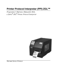
Dark Printing
A DARK parameter, available in the Alpha, Reverse, and Bar Code
commands, is a double-strike feature which produces bolder, darker text,
denser black backgrounds for reverse print, and extra-dark, more readable
bar codes.
A DARK parameter used with alphanumeric text in the ALPHA command will
print using a bold font.
The extra darkness provided by the DARK parameter improves the Print
Contrast Ratio (PCR) and effectively extends the life of the ribbon. For bar
codes, the PCR describes the difference in light reflection between the bars
and spaces as a measurement of light/dark contrast in order to judge when a
printed bar code will not be dark enough to be read with accuracy by a
scanner. The extra dots used to produce the darker bar code do not change
the overall width of the wide bars. Figure 3 illustrates how the DARK
parameter adds two extra dot columns to wide bar code bars without
increasing bar width.
Due to the second hammer bank stroke required to plot the extra columns of
dots, print speed may be reduced up to half when the DARK parameter is
used with Bar Code commands. However, this decreased print speed should
be weighed against the significant increase in bar code PCR and extended
ribbon life.
ADDED COLUMNS OF DOTS
NORMAL MODE
DARK MODE
Figure 3. Dark Printing
28
Alphanumerics
Alphanumerics
Purpose
Defines and positions alphanumeric data on a form as a
“preprinted” static data field or as a dynamic data field.
Mode
CREATE
Format
ALPHA
[R;] [E;] [Cn;] [AFn;L;] [DIR;] [UC;] [DARK;] [POINT;]
[HSn; or HSDn;] SR; SC; VE; HE; (D)text(D)
STOP
ALPHA
The Alphanumeric command; enter ALPHA.
R
The optional reverse printing (white on black)
parameter. Enter R to specify a black background.
Note
The D parameter, used in earlier IGP/PGL versions, is
ignored. In addition, the L parameter, also used in earlier
IGP/PGL versions to specify a long reverse field for
descending characters in dynamic alphanumeric data, is
provided automatically. The IGP/PGL will ignore these
parameters if found in a command line.
E
The optional elongated character parameter. Enter
E to specify elongated character printing.
Elongated characters are double height and single
width. If used, the VE and HE parameters must be
7set to 0, or an error message will result. Elongated
character printing is also available with rotated
alphanumerics.
Cn
The optional horizontal compression parameter.
Enter C and replace n with 10, 12, 13, 15, 17 or 20
to specify the number of horizontal characters per
inch (cpi). 10 cpi is the default value. 10A = 10 cpi
OCR-A. 10B = 10 cpi OCR-B. If used, the VE and
HE parameters must be set to 0, or an error
message will result.
AFn;L
The optional dynamic data field parameters for
identifying the alphanumeric string location on a
form and for designating the length of the
alphanumeric string. If these parameters are used,
the actual text can not be entered during the Create
Form mode; it must be entered dynamically during
the Execute Form mode. Dynamically entering data
during the Execute Form mode permits changes to
the alphanumeric text without redefining or recreating the form. To use this field, perform the
following steps:
a.
Enter AF.
b.
Replace n with a number ranging from 1
through 512 to identify the alphanumeric string
29
Chapter
2
Command Codes
location on the form. The SR and SC
parameters specify the exact location of the
alphanumeric field identified by n.
DIR
c.
Replace L with a number equal to the number
of characters in the dynamic alphanumeric
string ranging from 1 through 512.
d.
Dynamically enter the alphanumeric string
itself in the Execute Form mode. The length of
the alphanumeric string must be equal to or
less than the value assigned to the length (L)
parameter. Refer to “Execute Form: Dynamic
Alphanumeric Data” on page 62.
e.
If the dynamic data field is used, do not enter
the ASCII TEXT parameter.
Optional parameter for rotating a character string.
Use the following codes to indicate the direction of
character rotation:
a.
Enter CW for 90 degree clockwise rotation.
b.
Enter CCW for 90 degree counterclockwise
rotation.
c.
Enter INV for inverted characters (180 degree
rotation).
The default orientation prints character strings in
the standard horizontal format.
30
UC
Enter UC to specify uppercase-only characters.
When uppercase-only is specified, all lowercase
alpha character codes are converted automatically
to uppercase. Consequently, do not specify
uppercase-only characters if lowercase characters
are required.
DARK
Optional parameter to produce bolder text. Enter
DARK or D. (D is also allowed in the ALPHA
command only.) More information about dark
printing is provided on page 28.
SR
Defines the starting row of the alphanumeric data.
Enter a value ranging from row 1 through one less
than the length of the form. Character row or dot
row is specified based on the Scale command
(page 83), or use the CP.DP format (page 26).
SC
Defines the starting column of the alphanumeric
data. Enter a value ranging from column 1 through
one less than the width of the form. Character
column or dot column is specified based on the
Scale command (page 83), or use the CP.DP
format (page 26).
Alphanumerics
POINT
Optional parameter that changes the units for the
vertical and horizontal expansion values. When the
point parameter is present the VE value defines the
font height in 1/72 of an inch (i.e. points). If the HE
value is non-zero, it defines the character width in
1/72 of an inch, otherwise the character width is the
standard width for the chosen height. Cannot be
used with elongated (E) and compressed (Cn)
parameters.
HSn or HSDn Horizontal Spacing. The value n indicates the
number of extra dots to add between each
character.
HS = the value is in 60 DPI dots
HSD = the value is in printer dots.
VE
Defines the vertical expansion factor to enlarge
characters vertically. Enter a value between 0 and
113. Zero specifies the standard font (no
expansion). A VE value must be entered.
Elongated (E) and compressed (Cn) characters
cannot be used with a vertical expansion other than
zero.
HE
Defines the horizontal expansion factor to enlarge
characters horizontally. Enter a value between 0
and 113. Zero specifies the standard font (no
expansion). An HE value must be entered.
Elongated (E) and compressed (Cn) characters
cannot be used with a horizontal expansion other
than zero.
(D)
The printable character (quotation marks for
example) identifying the start and finish of the
alphanumeric string. Enter any printable character
other than a slash (/), the SFCC, or a character
used within the alphanumeric string itself. You must
use the same character at both ends of the
alphanumeric string, but it will not print with the
data.
text
The group of ASCII characters (the alphanumeric
string) to print. Enter any of the standard ASCII
printable characters (except the character used to
delimit the string in the D parameter). The data
appears as “prepositioned” information on the form
beginning at the location specified by SR and SC.
This is the “fixed” or static alphanumeric data; once
defined on the form, it is changed only by redefining
the form using the Alphanumeric command.
STOP
Stop indicates the end of the Alphanumeric
command; enter STOP, and the IGP will wait for a
new command. If not entered, the IGP will wait for
another set of Alphanumeric command parameters.
31
Chapter
2
Command Codes
Comments As dynamic data, the location of the alphanumeric field is
established in the Create Form mode and the actual
alphanumeric data is continuously redefined before placement on
the form in the Execute Form mode. You can also rotate and
reverse print the alphanumeric string using this command.
Example
The following program and example in Figure 4 illustrates the
Alphanumeric command capabilities. To illustrate positioning,
starting row and column are indicated on the example but do not
necessarily reflect actual location on the page. Notice the same
starting row is used for all “EXAMPLE” characters, and they are
all aligned on the same baseline (or bottom), regardless of
expanded or compressed parameters. The string rotates around
the point of intersection of the starting row and columns shown by
the “pinwheel” E. A rotated 10 cpi character establishes the
baseline for all character sizes.
~CREATE;TEST
ALPHA
36;37;4;4;*E*
36;41;2;3;*X*
36;44;2;2;*A*
36;46;1;1;*M*
C13;36;47;0;0;*P*
C15;36;48;0;0;*L*
C17;36;49;0;0;*E*
CW;36;60;2;2;*CLOCK*
CW;42;60;4;4;*WISE*
CCW;58;26;2;3;*COUNTER*
CCW;45;26;2;2;*CLOCK*
CCW;39.2;26;1;1;*WISE*
INV;54.5;58;0;0;*INVERTED*
R;INV;54.5;49;0;0;*REVERSE PRINT*
45;48;0;0;*E*
CW;UC;45;48;0;0;*E*
CCW;45;48;0;0;*E*
INV;45;48;0;0;*E*
STOP
END
~EXECUTE;TEST
~NORMAL
32
Alphanumerics
ROW 36
ROW 39.2
COLUMN 37
COLUMN 49
COLUMN 48
ROW 45
COLUMN 60
ROW 54.5
ROW 58
COLUMN 58
COLUMN 26
Figure 4. Alphanumeric Example
33
Chapter
2
Command Codes
Alphanumerics, Incremental Fields
Purpose
The incremental fields feature updates alphanumeric (and bar
code) data fields in a numeric or alphabetical manner
automatically using just one set of data sent from the host
computer. Incremental alphanumeric data fields can be applied to
fixed (static) data (page 38), or dynamic data (page 40).
Mode
CREATE (for fixed data) or EXECUTE (for dynamic data)
Note
Throughout the discussion of incremental fields, the term
“increment” or “incremental” means the field is automatically
updated by a specified amount (or increment). The field can
actually be increased/decreased in specified
increments/decrements within the command.
Comments Incremental fields can increase or decrease, repeat at specified
intervals before updating, and reset to the starting value after a
specified number of increments. A maximum of 65,535 fields can
print.
Using Incremental Alphanumeric Data
Incrementing is controlled with the STEPMASK and STARTDATA command
parameters as described in Table 5. The parameters are part of the
Incremental Alphanumeric Fixed Data command or part of the Execute
command when using incremental alphanumeric dynamic data.
The STEPMASK parameter performs the following three functions:
1. Defines the increment amount (step);
2. Defines the number of characters allowed in the data field (STARTDATA);
and
3. Provides a “mask” to link or unlink subfields of the data to be incremented
independently. The data provided in the STEPMASK field combined with
the data in the STARTDATA field determine the result of these functions.
The increment amount is defined by the numeric value of the STEPMASK
data. For example, a STEPMASK value of 1 increments the STARTDATA by
1; a STEPMASK value of 2 increments the STARTDATA by 2.
The maximum number of characters allowed in the STARTDATA field is
defined by the number of characters in the STEPMASK field; the
STARTDATA field cannot contain more characters than used in the
STEPMASK field.
34
Alphanumerics, Incremental Fields
Linked and unlinked masking of subfields within the STARTDATA is defined
by the L value in the STEPMASK field. L indicates linked but non-incremental
data in the corresponding position of the STARTDATA field; any alpha
character other than L in the STEPMASK field indicates a non-incremental,
non-linked STARTDATA subfield.
Table 5. Increment Alphanumeric
STEPMASK
START DATA
Character Type and Function
0-9
A-Z
Alpha characters incremented by
amount in STEPMASK field
0-9
0-9
Numeric characters incremented
by amount in STEPMASK field
0-9
Space
Same character type as character
in the next right adjacent, linked
increment position. Character
type will be numeric if in least
significant position.
0-9
Not A - Z or 0 - 9
Error
Not 0 - 9 or L
Any
Non-incrementing alphanumeric
character
L
Any
Linked, non-incrementing
alphanumeric character
The examples on the following pages illustrate incremental alphanumeric data
fields. All cases in the examples use a repeat count parameter value of 1 and
a reset count parameter value of 0. The three vertical dots illustrate the
natural progression for each column and unit of data based on the
incremental count and its impact on linked and unlinked data fields.
35
Chapter
36
2
Command Codes
Value
Description
STARTDATA:
STEPMASK:
ABC123
000001
Printed Results:
ABC123
ABC124
......
......
......
ABC999
ABD000
......
......
......
ZZZ999
AAA000
Linked subfields: ABC and 123
RPT = 1
RST = 0
Value
Description
STARTDATA:
STEPMASK:
1ABC123
0LLL001
Printed Results:
1ABC123
1ABC124
.
...
.
...
.
...
1ABC999
2ABC000
Two separate but linked numeric
subfields: 1 and 123, while fixed data
ABC is nonincrementing
RPT = 1
RPT = 0
Value
Description
STARTDATA:
STEPMASK:
ABC123
001XX1
Printed Results:
ABC123
ABD124
. .
. .
. .
ABI129
ABJ120
Two separate unlinked subfields:
ABC and 3, while fixed data 1 and 2
is nonincrementing
RPT = 1
RPT = 0
Alphanumerics, Incremental Fields
Value
Description
STARTDATA:
STEPMASK:
___1
0001
Printed Results:
___1
___2
....
....
....
__10
Single numeric field with leading
spaces (_)
RPT = 1
RPT = 0
Value
Description
STARTDATA:
STEPMASK:
_AA98
0LL01
Printed Results:
_AA98
.
.
.
.
.
.
1AA00
Two separate but linked numeric
subfields: AA and 98, with leading
space (_); fixed data AA is
nonincrementing
RPT = 1
RST = 0
Value
Description
STARTDATA:
STEPMASK:
_42AR
0LL01
Printed Results:
_42AR
_42AS
. ..
. ..
. ..
_42ZZ
A42AA
Two separate but linked alpha
subfields: A and R, with leading
space (_); fixed data 42 is
nonincrementing
RPT = 1
RST = 0
Value
Description
STARTDATA:
STEPMASK:
9AA02
-XXX01
Printed Results:
9AA02
9AA01
9AA00
9AA99
..
..
..
9AA03
Single numeric field decremented by
1, while fixed data 9 and AA are
nonincrementing.
37
Chapter
2
Command Codes
Alphanumerics, Incremental: Fixed Data Fields
Purpose
To automatically increment/decrement fixed alphanumeric data
fields.
Mode
CREATE
Note
Format
In the command format below, incremental alphanumeric
command parameters are shown in boldface type.
Standard alphanumeric command parameters and optional
nonincremental parameters are shown in italics and are
described in the Alphanumerics section (starting on page
29). Due to space constraints, the command parameters are
separated into two lines. During actual IGP input, DO NOT
separate command parameters.
ALPHA
[R;] [E;] [Cn;] I; [DIR;] [UC;] [DARK;] [POINT;] [HSn or HSDn;]
SR; SC; VE; HE; [idir] STEPMASK; [RPTn;] [RSTn;]
(D)STARTDATA(D)
STOP
I
Identifies this alphanumeric command as an
Incremental Alphanumeric command; enter I.
idir
The optional increment direction parameter to
specify an increment (add) or decrement (subtract)
to the data. Enter a plus sign (+) or leave the field
blank to increment (the default). Enter a minus sign
(-) to decrement.
STEPMASK Defines the increment amount (step), the number
of character positions in the data field, and provides
a mask to control the increment function on specific
parts of the data. Refer to Table 5 on page 35 for
complete information on STEPMASK parameter
values.
RPTn
The optional incremental repeat count parameter to
specify the number of times a particular field value
is repeated before it is incremented. A repeated
field value is useful when printing multiple
rows/columns of identical labels before increasing
to the next value.
To use the repeat count parameter, enter RPT and
replace n with a numeric value ranging from 1 to
65,535 to specify the repeat count. The default
repeat count parameter is 1, which will increment
the field value each time it prints.
38
Alphanumerics, Incremental: Fixed Data Fields
RSTn
The optional incremental reset count parameter to
specify the number of times an incremented field is
printed (on one or more forms) before it is reset to
the starting value. A reset count is useful when
printing a hierarchy of fields where a low-level field
generates a sequence of numbers, is reset, and the
next higher field level is incremented (such as in a
unit/box/carton application). To use the reset count
parameter, enter RST and replace n with a number
ranging from 1 to 65,535 to specify the reset count.
The default reset count value is 0.
STARTDATA Defines the starting value of the incrementing field.
Enter the appropriate value. Refer to “Using
Incremental Alphanumeric Data” on page 34 for
complete information on STARTDATA and
STEPMASK parameter values.
The maximum amount of STARTDATA characters
must be equal to or less than the number of
characters in the STEPMASK field. If the number of
data characters is less than the number used in
STEPMASK, the data will print right justified with
preceding spaces. Characters allowed for
incrementing fields (STEPMASK values of 0 - 9)
are numeric 0 - 9 and alpha A - Z (uppercase only).
Any printable character is allowed in
nonincrementing fields (STEPMASK values not 0 9).The STARTDATA must be enclosed within
standard printable character delimiters just as a
standard alphanumeric data field is enclosed within
delimiters.
Comments The Incremental Alphanumeric Fixed Data Fields command is a
revised version of the standard IGP alphanumeric command, but
it does not replace the standard alphanumeric command.
~CREATE;TEST;288
VDUP;3;6
ALPHA
I;6;5;4;4;-00001;*12345*
STOP
VDUP;OFF
END
~EXECUTE;TEST
~NORMAL
39
Chapter
2
Command Codes
Alphanumerics, Incremental: Dynamic Data Fields
Purpose
Automatically increments/decrements dynamic alphanumeric
data fields. Specifies the location and size of the incremental
dynamic data field during the Create Form mode. STEPMASK
and STARTDATA parameters are supplied in the Execute
command during the Execute Form mode.
Mode
CREATE
Note
Format
In the command format below, incremental alphanumeric
command parameters are shown in boldface type; standard
alphanumeric command parameters and optional
nonincremental parameters are shown in italics.
ALPHA
[R;] [E;] [Cn;] IAFn;L; [DIR;] [UC;] [DARK;] [POINT;]
[HSn or HSDn;]SR; SC; VE; HE STOP
IAFn;L
40
Identifies this alphanumeric command as an
Incremental Alphanumeric Dynamic Data Field
command. The command parameter string
identifies the incremental dynamic data field
location on the form and defines the length of the
alphanumeric data. If these parameters are used,
the STEPMASK and STARTDATA parameters can
not be entered in the Create Form mode; they are
entered dynamically during the Execute Forms
mode. To use the incremental dynamic data field,
perform the following steps:
a.
Enter IAF to specify an incremental
alphanumeric dynamic data field.
b.
Replace n with a number ranging from 1
through 512 to identify the alphanumeric string
location on the form. The standard
alphanumeric SR and SC command
parameters specify the exact location of the
field identified by n.
c.
Replace L with a number equal to the number
of characters in the dynamic alphanumeric
string (STARTDATA) ranging from 1 through
280.
d.
Dynamically enter the STEPMASK and
STARTDATA parameters in the Execute Form
mode. The length of the data must be equal to
or less than the value assigned to the length
(L) parameter. Refer to “Execute Form:
Incremental Dynamic Data” on page 65 for
more information.
Alphanumerics, Incremental: Dynamic Data Fields
Comments The Incremental Alphanumeric Dynamic Data Fields command is
a variation of the standard IGP Alphanumeric command, but does
not replace the standard alphanumeric command.
As with standard dynamic data fields, incremental dynamic data
fields allow the starting data to be changed without changing the
form definition program. Increment parameters can also change
with each new job without changing the form definition program.
Duplicating Incremental Alphanumeric Fields — Incremental
alphanumeric fixed and dynamic data fields are duplicated
horizontally using the HDUP command and vertically using the
standard VDUP command. Duplicated incremental fields
increment in left-to-right, top-to-bottom order. The following
examples illustrate the results of duplicated incremental fields.
Description
Value
STARTDATA:
STEPMASK:
Single numeric field (01)
RPT = 1
RST = 0
HDUP = 3
VDUP = 2
01
01
Printed Results:
Page #1:
01
04
02
05
03
06
Page #2:
07
10
08
11
09
12
Field A
STARTDATA:
STEPMASK:
A01
X01
STARTDATA:
STEPMASK:
Field B
B01
X01
Unlinked subfields, alpha (A),
numeric (01)
RPT = 3
RST = 9
HDUP = 3
VDUP = 3
Unlinked subfields, alpha (B),
numeric (01)
RPT = 1
RST = 0
(No HDUP or VDUP)
Printed Results:
Page #1:
A01
A02
A03
A01
A02
A03
A01
A02
A03
B01
Page #2:
A01
A02
A03
A01
A02
A03
A01
A02
A03
B02
Example
The following program will produce the Incremental Alphanumeric
data example shown above. The program elements are also
defined. (Refer to the command format on page 38.)
41
Chapter
2
Command Codes
~CREATE;TEST
HDUP;3;6
VDUP;3;1
ALPHA
I;1;1;0;0;001;RPT3;RST9;*A01*
STOP
VDUP;OFF
HDUP;OFF
ALPHA
I;1;18;0;0;001;RPT1;*B01*
STOP
END
~EXECUTE;TEST;2
~NORMAL
where:
I;1;1;0;0;001;RPT3;RST9;*A01*
Incremental alphanumeric command;
SR of 1; SC of 1;
VE and HE are 0;
001 stepmask increments by 1;
RPT3 repeats each field value 3 times;
RST9 prints and increments each field 9 times
before resetting;
*A01* is the starting value.
I;1;18;0;0;001;RPT1;*B01*
Incremental alphanumeric command;
SR of 1; SC of 18; VE and HE are 0;
001 stepmask increments by 1;
RPT1 repeats each field value once;
RST0 is not used (default value is 0), prints and
increments continuously without resetting;
*B01* is the starting value.
~CREATE;TEST;288
VDUP;3;6
ALPHA
IAF1;5;6;5;4;4
STOP
VDUP;OFF
END
~EXECUTE;TEST
~IAF1;+00002;*45678*
~NORMAL
42
Boxes
Boxes
Purpose
Produces any variety of rectangular boxes.
Mode
CREATE
Format
BOX
LT; SR; SC; ER; EC
STOP
BOX
The Box command; enter BOX. Boxes expand
down and to the right from the given row and
column.
LT
Defines the line thickness, measured in dots. Line
thickness is based on dot dimensions of 1/72 inch
both horizontally and vertically, so that line
thickness is equal in both directions. Enter a value
of 1 or greater.
SR
Defines the starting row of the box. Enter a value
ranging from row 1 through one less than the length
of the form. Character row or dot row is specified
based on the Scale command (page 83), or use the
CP.DP format (page 26).
SC
Defines the starting column of the box. Enter a
value ranging from column 1 through one less than
the width of the form. Character column or dot
column is specified based on the Scale command
(page 83), or use the CP.DP format (page 26).
ER
Defines the ending row of the box. Enter a value
ranging from row 2 through the last row of the form.
The ending row must be greater than the starting
row. Character row or dot row is specified based on
the Scale command (page 83), or use the CP.DP
format (page 26).
EC
Defines the ending column of the box. Enter a
value ranging from column 2 through the last
column of the form. The ending column must be
greater than the starting column. Character column
or dot column is specified based on the Scale
command (page 83), or use the CP.DP format
(page 26).
STOP
Stop indicates the end of the Box command; enter
STOP, and the IGP will wait for a new command. If
not entered, the IGP will wait for another set of Box
command parameters.
43
Chapter
2
Command Codes
Example
The following program and example in Figure 5 defines two
boxes. To illustrate positioning, the starting row and column are
indicated on the example but do not necessarily reflect actual
location on the page. (Note the position of the ending row and
column.)
BOX
3;24;16;51;63
2;44;48;46;58
STOP
(One box three dot rows thick)
(One box two dot rows thick)
COLUMN 16
ROW 24
COLUMN 48
ROW 44
ROW 46
COLUMN 58
ROW 51
COLUMN 63
Figure 5. Box Example
44
box.ex
Compressed Print (Density)
Compressed Print (Density)
Purpose
Defines the horizontal print density in characters per inch (cpi).
Mode
NORMAL, EXECUTE
Format
(cc) DENSITY;n
(cc)
The Special Function Control Code.
DENSITY
The Density command; enter DENSITY.
n
Selects the density in cpi, OCR-A, or OCR-B; enter
a value of 10, 12, 13, 15, 17, or 20 to specify the
density in characters per inch (the default is 10 cpi),
or 10A to select 10 cpi OCR-A or 10B to select 10
cpi OCR-B.
Comments Print density formats of 10, 12, 13, 15, 17, or 20 cpi are available.
Standard print density is 10 cpi. After a Density command is
entered, all subsequent alphanumerics print at the specified
density until another Density command, a Normal mode
command, or a Reset command is entered. The Density
command also permits the standard printer editing function
(carriage return editing). After the Density command is entered,
data in the print buffer can be edited as described in your printer
User’s Guide.
Example
The following command selects 15 cpi printing format until
another Density command, a Normal mode command, or a Reset
command is entered.
~DENSITY;15
45
Chapter
2
Command Codes
Configuration
Purpose
Places the IGP/PGL in the Configuration mode, where changes
to any or all of the IGP/PGL configuration parameters via
software control can be made instead of from the printer control
panel.
Mode
NORMAL
Note
Format
A separate line is required for the CONFIG command, the
parameters and values, and the END command.
(cc)CONFIG
parameter;value
END
(cc)
The SFCC.
CONFIG
The Configuration command; enter CONFIG.
parameter;value
The parameter for which a configuration change is
desired, and the value associated with that
parameter. The available parameters and the
values associated with these parameters are listed
in Table 6.
END
Note
46
Terminates the CONFIG command; enter END.
All CONFIG parameters except RESET must be followed by
a semicolon (;). Any CONFIG parameters not entered in
UPPERCASE and exactly as listed in Table 6 will result in
an Error 156. (Refer to the “Error Codes” chapter.)
Configuration
Table 6. Configuration Parameters
Configuration Parameter
Value
AI 00 SPACES
0 = Disabled; Non-Zero = Enabled
AUTO WRAP
0 = Disabled; Non-Zero = Enabled
CARRIAGE RETURN DEF
0 = Disabled; Non-Zero = Enabled
CR EDIT
0 = Disabled; Non-Zero = Enabled
ERROR REPORT
0 = Off; 1 = On; 2 = Debug
EXT EXECUTE COPY
0 = Disabled; Non-Zero = Enabled
HOST FORM LENGTH
0 = Disabled; Non-Zero = Enabled
IGNORE CHAR
0-255 = the selected ignore char;
any other value = ignore mode off
IGP100 COMPATBL
0 = Disabled; Non-Zero = Enabled
I-2/5 SELECTION
1 = Trailing Spaces
2 = X2DPD
3 = Modulo 7 CD
any other value = Leading Zero
LINE FEED DEF
0 = Disabled; Non-Zero = Enabled
LPI
6, 8, 9 or 10
OPTIMIZED RATIO
0 = Disabled; Non-Zero = Enabled
PRINTER PI LINE
0 = Disabled; Non-Zero = Enabled
SFCC
1-255
SKIP PREFIX
0 = Disabled; Non-Zero = Enabled
SLASH ZERO
0 = Disabled; Non-Zero = Enabled
SLEW RANGE
0 = 15; Non-Zero = 16
SO CHAR
0 = Disabled; Non-Zero = Enabled
TRUE FORM SLEW
0 = Disabled; Non-Zero = Enabled
UPPERCASE
0 = Disabled; Non-Zero = Enabled
POWER ON IGP/PGL
0 = Disabled; Non-Zero = Enabled
UPC DESCENDERS
0 = Disabled; Non-Zero = Enabled
47
Chapter
2
Command Codes
Comments The IGP/PGL configuration parameters available are defined in
your User’s Guide.
Any or all parameters can be used within one CONFIG
command, and they can be listed in any order. List each
parameter;value on a separate line, terminating with the END
command. Default configuration values can be reset using the
CONFIG command.
Parameters not followed by a value, and parameters followed by
any non-zero value are interpreted as “true” or “enabled” values.
For carriage return and line feed definitions, a zero value does
not change the data stream. However, for non-zero values, a
carriage return character or line feed character will be interpreted
as a carriage return plus a line feed.
Parameters not listed in this command remain unchanged. If a
parameter error is detected for parameters other than 0 or 1 (i.e.,
SFCC, Top/Bottom Margin, Left Margin), the value will default to
the current configuration from disk/flash.
Example 1 The following command enables IGP/PGL Auto Wrap, disables
Auto Eject, and selects 6 lpi printing.
~CONFIG
AUTO WRAP;1
AUTO EJECT;0
LPI;6
END
Example 2 The following command resets all control panel IGP/PGL
configuration parameters back to default values.
~CONFIG
RESET
END
48
Corners
Corners
Purpose
Defines corner sets.
Mode
CREATE
Format
CORNER
LT; SR; SC; ER; EC; VL; HL
STOP
CORNER
The Corner command; enter CORNER. Corners
expand down and to the right from the given row
and column.
LT
Defines the line thickness, measured in dots. Line
thickness is based on dot dimensions of 1/72 inch
both horizontally and vertically, so that line
thickness is equal in both directions. Enter a value
of 1 or greater.
SR
Defines the starting row of the corner. Enter a value
ranging from row 1 through one less than the length
of the form. Character row or dot row is specified
based on the Scale command (page 83), or use the
CP.DP format (page 26).
SC
Defines the starting column of the corner. Enter a
value ranging from column 1 through one less than
the width of the form. Character column or dot
column is specified based on the Scale command
(page 83), or use the CP.DP format (page 26).
ER
Defines the ending row of the corner. Enter a value
ranging from row 2 through the last row of the form.
The ending row must be greater than the starting
row. Character row or dot row is specified based on
the Scale command (page 83), or use the CP.DP
format (page 26).
EC
Defines the ending column of the corner. Enter a
value ranging from column 2 through the last
column of the form. The ending column must be
greater than the starting column. Character column
or dot column is specified based on the Scale
command (page 83), or use the CP.DP format
(page 26).
VL
Defines the length of the vertical arm (including the
line thickness) of each corner in the set. Enter a
value of 1 or greater specified in character or dot
rows based on the Scale command (page 83), or
use the CP.DP format (page 26).
HL
Defines the length of the horizontal arm (including
the line thickness) of each corner in the set. Enter a
value of 1 or greater specified in character or dot
columns based on the Scale command (page 83),
or use the CP.DP format (page 26).
49
Chapter
2
Command Codes
STOP
Example
Stop indicates the end of the CORNER command;
enter STOP, and the IGP will wait for a new
command. If not entered, the IGP will wait for
another set of Corner command parameters.
The following program specifies a corner set as shown in Figure
6. To illustrate positioning, the starting row and column are
indicated on the example but do not necessarily reflect actual
location on the page. (Note the position of the ending row and
ending column; they do not include the line thickness.)
CORNER
5;27;27;42;55;4;6
STOP
(Each corner in the set is 5
dot rows thick, 4 character
rows high, 6 character columns
wide)
COLUMN 27
HORIZONTAL LENGTH
6 COLUMNS
ROW 27
VERTICAL
LENGTH
4 ROWS
ROW 42
COLUMN 55
Figure 6. Corner Example
50
Create
Create
Purpose
Places the IGP in the Create Form mode, where forms and form
elements can be defined using the appropriate commands.
Mode
NORMAL
Format
(cc)CREATE; [/]formname [;FL] [;DISK]
(cc)
The Special Function Control Code.
CREATE
The Create Form mode command; enter CREATE.
/
The optional debug character to check the program
line by line for incorrect parameters and print
boundaries using the current page size; enter the
slash symbol (/) to debug the program. No checks
are made until the completed program is sent to the
IGP for storage (when the form is executed by
printing the file with the IGP program). Then the
form name is entered into the directory, and the
program is evaluated. If errors are detected, the
program will print, line by line (including the error on
the line where the error occurs), followed by the
error-free sections of the form. Correct all errors
and delete the slash. Refer to “Solving Program
Errors” on page 248.
formname
Defines the form name of the form being created.
The form name should be no more than 15
characters in length. Refer to page 24 for a list of
allowable form name characters. If a form is
created with the same name as a form already
existing in memory, the newly created form will
replace the existing form. All future reference to the
form (editing, executing, or deleting the form from
the directory) must be made using the assigned
name.
FL
The optional forms length parameter to specify the
maximum length of the form. (Form length cannot
exceed the physical length of the page). Specify the
form length in one of three ways:
a.
Enter 0 to define a form of unspecified length.
The form will end after the longest element;
that is, the form length is automatically
controlled to contain all elements without extra
length beyond the longest element. This can
be used to eliminate wasted paper after
producing short forms.
b.
Enter a value for the form length ranging from
1 through 65,535 to specify the forms length in
dot rows. (12 dot rows per line = 6 lpi spacing;
9 dot rows per line = 8 lpi spacing.)
51
Chapter
2
Command Codes
c.
DISK
Example
To specify the default forms length of 792 dot
rows (11 inches at 6 lpi), do not enter a value
in the form length parameter.
Optional parameter to store the form on the
printer’s flash memory. Enter DISK.
The following command creates a form named ORDER with the
default forms length:
(cc)CREATE;ORDER
Delete Form
Purpose
Deletes the form identified by the form name from the directory
and the IGP memory.
Mode
NORMAL
Format
(cc)DELETE FORM; formname [;DISK]
(cc)
The Special Function Control Code.
DELETE FORM
The Delete Form command; enter DELETE FORM.
formname
Identifies the form to be deleted. Enter the name of
the form exactly as it was created. You can delete
an entire form directory by inputting *ALL as the
form name.
DISK
Optional parameter to delete the form from the
flash memory where it was originally stored. Enter
DISK.
Comments For more information, refer to the Directory Example on page 247
and the Delete Example on page 248.
Example
The following command deletes the form named “PAY#” from the
directory, IGP memory, and the printer’s flash memory.
~DELETE FORM;PAY#;DISK
52
Delete Logo
Delete Logo
Purpose
Deletes the logo identified by the logo name from the directory
and the IGP memory.
Mode
NORMAL
Format
(cc)DELETE LOGO; logoname [;DISK]
(cc)
The Special Function Control Code.
DELETE LOGO
The Delete Form command; enter DELETE LOGO.
logoname
Identifies the logo to be deleted. Enter the name of
the logo exactly as it was created. You can delete
an entire logo directory by inputting *ALL as the
logo name.
DISK
Optional parameter to delete the logo from the flash
memory where it was originally stored. Enter DISK.
Comments Printing a form that contains a deleted logo will produce an error
message. For more information, refer to the Directory Example
and the Delete Example on pages 205 and 207.
Example
The following command deletes the logo named “MEMO” from
the directory, IGP memory and the printer’s flash memory.
~DELETE LOGO;MEMO;DISK
Directory
Purpose
Prints the following information: (1) all defined forms and logos,
(2) logo assignment to forms, and (3) memory usage and
availability.
Mode
NORMAL
Format
(cc)DIRECTORY [;DISK]
(cc)
The Special Function Control Code.
DIRECTORY The Directory command; enter DIRECTORY.
DISK
Optional parameter to specify the forms and logos
stored on the flash memory. Enter DISK.
Comments As many forms and logos as printer memory allows may be
stored in IGP memory. If the memory is full, the form will not print;
available space in the memory must be at least the size of the
form being executed.
For more information, refer to the Directory Example on page
247.
53
Chapter
2
Command Codes
Duplication, Horizontal
54
Purpose
Defines both the number of times form elements are duplicated
horizontally and the spacing between each duplication.
Mode
CREATE
Format
HDUP; dup#; offset#
elements to be duplicated
HDUP;OFF
HDUP
The Horizontal Duplication command; enter HDUP.
dup#
Specifies number of times the entered form
element(s) will repeat horizontally. Enter a value
ranging from 1 through 512.
offset#
Specifies the horizontal offset to establish the
horizontal spacing between each duplication of the
form element(s) specified in the body of the
command. Enter a value in terms of dot or
character columns based on the Scale command
(page 83), or use the CP.DP format (page 26). The
offset is from starting column to starting column.
HDUP;OFF
Terminates the Horizontal Duplication command;
enter HDUP;OFF. If not entered, the IGP expects
another form element to be defined for duplication.
A single HDUP command can define different types
of elements for duplication.
Duplication, Horizontal
Example
The following example is a horizontal duplication of a series of
vertical lines. To illustrate positioning, starting row and column
are indicated on the example but do not necessarily reflect actual
location on the page.
HDUP;14;4
VERT
1;10;59;59.6
1;10.3;58.9;59.9
1;11;58.6;60
1;11.3;58.3;60.3
1;12;58;60.6
1;12.3;58.3;60.3
1;13;58.6;60
1;13.3;58.9;59.9
STOP
HDUP;OFF
(14 dupes with 4-character column spacing)
(Command to be duplicated horizontally)
(Note CP.DP format: 59.6)
(Terminates the duplicated element command)
(Terminates the horizontal duplication)
COLUMN 10
COLUMN 11
COLUMN 12
COLUMN 13
ROW 58
DUPLICATING THE SET HORIZONTALLY 14 TIMES
ROW 60.6
COLUMN 13.3
COLUMN 12.3
COLUMN 11.3
COLUMN 10.3
hdup.ex
55
Chapter
2
Command Codes
Duplication, Vertical
Purpose
Defines both the number of times elements are duplicated
vertically and the spacing between each duplication.
Mode
CREATE
Format
VDUP; dup#; offset#
elements to be duplicated
VDUP;OFF
Example
VDUP;3;2
HORZ
1;52;15;65
STOP
VDUP;OFF
COLUMN 15
ROW 52
ROW 54
ROW 56
56
VDUP
The Vertical Duplication command; enter VDUP.
dup#
Specifies number of times the entered form
element(s) will repeat vertically. Enter a value
ranging from 1 through 512.
offset#
Specifies the vertical offset to establish the vertical
spacing between each duplication of the form
element(s) specified in the body of the command.
Enter a value in terms of dot or character columns
based on the Scale command (page 83), or use the
CP.DP format (page 26). The offset is from starting
row to starting row.
VDUP;OFF
Terminates the Vertical Duplication command;
enter VDUP;OFF. If not entered, the IGP expects
another form element to be defined for duplication.
A single VDUP command can define different types
of elements for duplication.
The following example is a vertical duplication of one horizontal
line. The line is duplicated three times. To illustrate positioning,
the starting row and column are indicated on the example but do
not necessarily reflect actual location on the page.
(3 duplications with 2-char. row spacing)
(Command to be duplicated vertically)
(Terminates the duplicated element command)
(Terminates the vertical duplication)
COLUMN 65
Emulation Switching
Emulation Switching
Purpose
To switch the active emulation from PGL to the emulation
selected.
Mode
NORMAL
Format
(cc)EMULATION; emulation
EMULATION The Emulation Switch command.
emulation
Specifies the emulation to activate. Currently, the
only selection is VGL (Code V). Enter VGL. If VGL
is not the selection, this command is then ignored.
Comments This command is only processed when VGL is included in the
software package. If not, this command is simply ignored. The
switching of emulations causes PGL to perform a soft reset.
Therefore, front panel selections return to their saved state, and
all forms and logos resident in RAM memory are deleted.
End
Purpose
Terminates the current mode of operation and must be used
before entering a new mode command (EXECUTE, LOGO,
NORMAL, or even CREATE).
Mode
CREATE
Format
END
Comments After the End command is received, the IGP flushes program
errors, stores the error-free portions of the form program just
completed, and then returns to the Normal mode. If the debug
slash (/) is included in the Create command, the program prints
with any corresponding error messages.
57
Chapter
2
Command Codes
Execute Form Mode
How to Use the Execute Command
Forms are printed in the Execute Form mode. In addition to printing the form
in the Execute Form mode, variable data can also be entered onto the form
“dynamically” during the Execute Form mode. This dynamic data input during
the Execute Form mode includes page numbers, alphanumeric data fields,
and bar code data fields. Pagination, described on page 78, is performed in
the Execute Form mode. Dynamic alphanumeric and bar code data require
additional commands within the Execute Form mode.
The fastest method for repeated forms printing is to use the form feed
character. Rather than sending a series of Execute/Normal commands, which
slows the process by performing an open-print-close form sequence, the form
feed character instructs the IGP to start a new page with new EVFU, dynamic
and overlay data using the existing Execute commands for the form. The
EVFU Data-Dynamic Data-Overlay Data-Form Feed Character sequence can
be repeated indefinitely while maintaining the optimum print speed within the
original Execute command.
Note
When a form count is not specified, a single line spacing (or
a line containing overlay data) must always separate an
EXECUTE command from a NORMAL command.
To Execute Forms Rapidly
In order to save reloading time, the IGP remembers the last form executed.
However, a form must be loaded if it was not the last form executed, if it was
used with a CREATE command since the last EXECUTE, or if any logo has
been created.
When the form is found in memory, it is loaded and execution resumes;
otherwise, the “FORM NOT FOUND” error is printed.
Print Formats in the Execute Form Mode
The Execute Form mode has two print formats. The standard execute
command format, shown on the next page, is used for executing
nonincremental data and incremental fixed data. An incremental execute
command format, containing two additional parameters, is used for executing
incremental dynamic data and is discussed on page 65.
During the Execute Form mode, the IGP responds to regular print format
commands such as 8 lpi, and elongated characters. Some commands can be
used in other modes in addition to the Execute Form mode. For example,
Compressed Print, Expanded Print, Execute, Ignore, Select Format, and
Vertical Line Spacing, which are also Normal mode commands, can be used
in the Execute or Create Form modes. The IGP alternate character set can
also be used in the Execute Form mode.
58
Execute Form: General Format
Execute Form: General Format
Purpose
Prints forms created in the CREATE mode.
Mode
NORMAL
Format
(cc)EXECUTE ;formname [;PAGEn] [;FC] [;ICNTn] [;IRSTn]
[;DISK] [EVFU Data]
[(cc)AFn; (D)ASCII text(D)]
[(cc)BFn; (D)data(D)]
[(cc)GFn; (D)logoname(D)]
[(cc)IAFn; [idir] STEPMASK; [RPTn;] [RSTn;](D)STARTDATA(D)]
[(cc)IBFn; [idir] STEPMASK; [RPTn;] [RSTn;](D)STARTDATA(D)]
[Overlay Data]
[Form Feed character]
(cc)NORMAL
Note
(cc)
The Special Function Control Code.
EXECUTE
The Execute Form command; enter EXECUTE.
formname
Identifies a previously defined form by name. Enter
the form name exactly as used when created.
PAGEn
The optional Pagination command; enter PAGE
and replace n with the decimal number of the
starting page in a sequence of multiple pages. The
number may be eight digits long and range
between 0 and 99999999. The next page after
99999999 is 0. Leave a blank space between the
PAGE command and the n value. The page
number will print on the form in the location defined
by the Page Number command in the Create Form
mode. If the location of the pagination field was not
specified in the Create Form mode, the page field is
printed in the upper left corner of the form.
FC
The optional form count parameter specifies the
number of copies of the form to print. Enter the
appropriate number. When the last page prints, the
IGP returns to the Normal mode automatically.
Do not use the form count parameter if dynamic data (AFn
and BFn parameters), incremental data (ICNT or IRST
parameters), overlay data, or EVFU data are used in the
Execute command.
ICNTn
The optional incremental form count. Enter ICNT
and the Incremental value as described in the
Execute Incremental Dynamic Data command
described on page 65.
IRSTn
The optional incremental reset count parameter.
Enter IRST and the reset value as described in the
Execute Incremental Dynamic Data command
described on page 65.
59
Chapter
2
Command Codes
DISK
Optional parameter that specifies to recall the form
from the flash memory. Enter DISK.
EVFU Data
Optional parameter to use the EVFU to overlay
data onto the form. (“EVFU Data” is not part of the
Execute command. It is shown in the command
sequence to indicate that actual EVFU data can be
entered following the Execute command.) Enter
EVFU data as described in Appendix C and on
page 61.
(cc)AFn;(D)ASCII text(D)
The Execute Dynamic Alphanumeric Data
command. Enter the dynamic alphanumeric data
during the Execute Form mode as described in
“Execute Form: Dynamic Alphanumeric Data” on
page 62.
(cc)BFn ;(D)data(D)
The Execute Dynamic Bar Code Data command.
Enter the dynamic bar code data during the
Execute Form mode as described in “Execute
Form: Dynamic Bar Code Data” on page 63.
(cc)GFn;(D)logoname(D)
The Execute Dynamic Logo Command. Enter the
name of the logo during the Execute Form mode as
described in “Execute Form: Dynamic Logo” on
page 64.
(cc)IAFn;[idir] STEPMASK;[RPTn;] [RSTn;] (D)STARTDATA(D)
The Execute Incremental Dynamic Alphanumeric
Data command. Supply the data as described on
page 66.
(cc)IBFn; [idir] STEPMASK; [RPTn;] [RSTn;] (D)STARTDATA(D)
The Execute Incremental Dynamic Bar Code Data
command. Supply the data as described on page
66.
Overlay Data Overlay data can be entered during the Execute
Form mode. (The words “Overlay Data” are not part
of the Execute command. They are shown in the
command sequence to indicate that actual overlay
data can be entered following the Execute
command.) Refer to “Execute Form: Overlay Data”
on page 67.
Form Feed Character
Optional command instructing the IGP to start a
new page with new EVFU, dynamic, and overlay
data using the existing Execute commands for the
current form. Using this EVFU Data-Dynamic Data
and Overlay Data-Form Feed Character sequence
can be repeated indefinitely, while maintaining the
optimum print speed, within the original Execute
command.
60
Execute Form: Electronic Vertical Format Unit
(cc)NORMAL The Normal mode command. If the form count
parameter was not used in the Execute command,
enter the SFCC and NORMAL to return the IGP to
the Normal mode. The Normal mode command is
input following all other Execute commands to
enter variable data. (Refer to the following
sections.) Input a line terminator to leave a blank
line before entering the Normal command.
Execute Form: Electronic Vertical Format Unit
Purpose
Provides an efficient method of rapidly slewing paper.
Mode
EXECUTE
Format
See Appendix C.
Comments The Electronic Vertical Format Unit (EVFU) is processed as
overlay data within the Execute Form mode. Detailed EVFU
information is provided in Appendix C.
The EVFU must be loaded while in the Execute Form mode and immediately
following the Execute command. After executing the form and returning to
Normal mode, the EVFU information is automatically deleted from printer
memory. To print the form again, re-send the EVFU command.
Several key points to operating the EVFU are listed below.
•
Send EVFU commands immediately following the Execute command or
the format form feeds.
•
•
The EVFU can be unloaded by issuing an END LOAD command only.
•
In those circumstances where the EVFU is being used to control the
forms length only, the IGP forms length parameter can be used in place of
the EVFU.
•
•
The maximum number of EVFU channels is 192.
The number of lines slewed is dictated by the current line spacing (lpi)
setting.
Changing the LPI unloads the EVFU.
61
Chapter
2
Command Codes
Execute Form: Dynamic Alphanumeric Data
Purpose
Incorporates the dynamic alphanumeric data into a previously
identified location on a form.
Mode
EXECUTE
Format
(cc)AFn; (D)ASCII text(D)
Note
(cc)
The Special Function Control Code.
AFn
Indicates a dynamic alphanumeric field (AF) and its
data (n). Enter AF and replace n with the number of
the data field corresponding to the number used to
identify the field when it was defined with the
Alphanumeric command in the Create Form mode.
(D)
The printable character identifying the start and
finish of the alphanumeric data. Enter any printable
character other than a slash (/), the SFCC, or a
character used within the data. The same character
must be used at both ends of the data field but will
not be printed with the data.
ASCII text
The group of ASCII characters (the alphanumeric
string) to print. Enter any of the standard ASCII
printable characters (except the character used as
delimiters described in the (D) parameter). The
data appears on the form at the location identified
by the value of n.
Be sure to enter Dynamic Alphanumeric Data after the
Execute command and/or EVFU data but before any
Overlay Data. (See the general Execute command format on
page 59.)
Comments The location for the dynamic alphanumeric data must have been
previously identified using the AFn;L parameters of the
alphanumerics command in the Create Form mode. Inputting
individual commands enters the new data into the identified
location each time the form is printed.
You can repeat the (cc)AFn;(D)ASCII text(D) sequence to
complete as many data fields as you defined on the form in the
Create Form mode. You can also combine the Execute Dynamic
Bar Code Data command in the same Execute command
sequence. Each “page” of dynamic data (the dynamic fields,
data, and overlay data) for the form must be separated from the
next page of new dynamic data by a form feed.
62
Execute Form: Dynamic Bar Code Data
Execute Form: Dynamic Bar Code Data
Purpose
Incorporates the dynamic bar code data into a previously
identified location on a form.
Mode
EXECUTE
Format
(cc)BFn; (D)data field(D)
Note
(cc)
The Special Function Control Code.
BFn
Indicates a dynamic bar code field (BF) and its data
(n). Enter BF and replace n with the number of the
data field corresponding to the number used to
identify the field when it was defined with the bar
code command during the Create Form mode.
(D)
The printable character (quotation marks for
example) identifying the start and finish of the bar
code data. Enter any printable character other than
a slash (/), the SFCC, or a character used within
the data. The same character must be used at both
ends of the data field but will not be printed.
data field
Enter the characters for the bar code data. The
character types allowed in the data varies with the
bar code type. Refer to the data field descriptions
for the selected bar code types. The data appears
on the form at the location identified by n.
Be sure to enter Dynamic Bar Code Data after the Execute
command and/or EVFU data but before any Overlay Data.
(See the general Execute command format on page 59.)
Comments The bar code location must have been previously identified using
the BFn;L or BFn parameters of a bar code command in the
Create Form mode. Use the appropriate bar code command to
enter the bar code data in that location. Inputting individual
commands enters new bar code data into the identified location
each time the form is printed. You can repeat the (cc)BFn;(D)data
field(D) sequence to complete as many bar code data fields as
were defined on the form in the Create Form mode. You can also
combine the Execute Dynamic Alphanumeric Data command in
the same Execute command sequence. Each “page” of dynamic
data (the dynamic fields, data, and overlay data) for the form
must be separated from the next page of new dynamic data by a
form feed.
63
Chapter
2
Command Codes
Execute Form: Dynamic Logo
Purpose
Incorporates the dynamic graphic logo into a previously identified
location of a form.
Mode
EXECUTE
Format
(cc)GFn;(D)logoname(D)
(cc)
The Special Function Control Code.
GFn
Indicates the dynamic logo field. Enter GF and
replace n with the number of the field
corresponding to when it was defined with the Logo
Call command during the CREATE form mode.
(D)
The printable character identifying the start and
finish of the logo name. Enter any printable
character other than a slash (/), the SFCC, or a
character used within the name. The same
character must be used at both ends of the data
field but will not be included in the logo name.
logoname
Enter the logo name. If the logo is not found in
DRAM, the flash memory is searched.
Comments The logo location must have been previously identified using the
GFn parameters of a logo call command in the Create Form
mode. Then use the appropriate logo command to enter the logo
data in that location. Inputting individual commands enters new
logo data into the identified location each time the form is printed.
You can repeat the (cc)GFn;(D)logoname(D) sequence to
complete as many logo fields as were defined on the form in the
Create Form mode. You can also combine the Execute Dynamic
Alphanumeric Data command in the same Execute command
sequence. Each “page” of dynamic data (the dynamic fields,
data, and overlay data) for the form must be separated from the
next page of new dynamic data by a form feed.
NOTE: There are no incremental logos.
64
Execute Form: Incremental Dynamic Data
Execute Form: Incremental Dynamic Data
Purpose
Incorporates incremental/decremental capability to dynamic
alphanumeric or bar code data supplied as a part of the Execute
Form mode.
Mode
NORMAL
Note
Format
Example
In the command below, incremental execute parameters are
shown in boldface type; standard execute command
parameters are shown in italics. The general execute format
is shown on page 59.
(cc)EXECUTE; formname [;PAGE n] [;FC] [;ICNTn] [;IRSTn]
ICNTn
Identifies the incremental form count to specify the
number of forms to generate with the incremental
fields automatically updated. Enter ICNT and
replace n with a value ranging from 1 through
65,535 to specify the number of forms.
IRSTn
The optional incremental reset count parameter to
specify the number of forms to generate before
resetting all incremental fields to their starting
values. The reset count parameter is useful in
dividing the total number of forms generated into
multiple groups of identical copies. To use this
parameter, enter IRST and replace n with a value
ranging from 1 through 65,535 to specify the reset
count (how many forms generated before resetting
the incremental fields). If the reset count value is
equal to or greater than the incremental count
value, the reset will never occur.
The following forms were generated from ICNT6, IRST2. (To
duplicate incremental fields within a form, refer to page 40.)
0
1
2
3
4
5
0
1
2
3
4
5
0
1
2
3
4
5
form1
form2
form3
form4
form5
form6
65
= ICNT6
Chapter
2
Command Codes
Supplying Dynamic Data for Incremental Fields
Incremental dynamic data fields are created in the Create Form mode using
the incremental alphanumeric or bar code commands. The incremental
dynamic data itself is supplied during the Execute Form mode at the top of the
form prior to any overlay data. The incremental dynamic data (either
alphanumeric or bar code data) can be changed with each new batch of
forms. Incremental dynamic data fields specified in the Create Form mode will
not appear on the form if corresponding incremental dynamic data is not
supplied in the Execute Form mode.
Format
For incremental dynamic alphanumeric data:
(cc)IAFn; [idir] STEPMASK; [RPTn;] [RSTn;] (D)STARTDATA(D)
For incremental dynamic bar code data:
(cc)IBFn; [idir] STEPMASK; [RPTn;] [RSTn;] (D)STARTDATA(D)
(cc)
The Special Function Control Code.
IAF
Identifies the command as an incremental
alphanumeric dynamic data; enter IAF.
IBF
Identifies the command as an incremental bar code
dynamic data; enter IBF.
n
Identifies the field number of the dynamic data field
as entered in the Create Form mode. Replace n
with the number used to identify the field when it
was defined.
idir
The optional increment direction parameter to
specify an increase or decrease of the data. Enter a
plus sign (+) or leave the field blank to increment
(the default). Enter a minus sign (-) to decrement.
STEPMASK Defines the increment amount (step), the number
of character positions in the data field, and provides
a mask to control the increment function on specific
parts of the data. Refer to “Incremental Bar Code
Fields” on page 208 or “Alphanumerics,
Incremental Fields” on page 34 for complete
information on STEPMASK parameter values.
RPTn
66
The optional incremental repeat count parameter to
specify the number of times a particular field value
is repeated before it is incremented. A repeated
field value is useful when printing multiple
rows/columns of identical labels before
incrementing to the next value. To use the repeat
count parameter, enter RPT and replace n with a
numeric value ranging from 1 through 65,535 to
specify the repeat count. The default repeat count
parameter is 1, which will increment the field value
each time it is printed.
Execute Form: Overlay Data
RSTn
The optional incremental reset count parameter to
specify the number of times an incremented field is
printed (on one or more forms) before it is reset to
the starting value. A reset count is useful when
printing a hierarchy of fields where a low-level field
generates a sequence of numbers, is reset, and the
next higher field level is incremented (such as in a
unit/box/carton application). To use the reset count
parameter, enter RST and replace n with a number
ranging from 1 through 65,535 to specify the reset
count. The default reset count value is 0.
STARTDATA Defines the starting value of the incrementing field.
The maximum amount of STARTDATA characters
must be equal to or less than the number of
characters in the STEPMASK field. If the number of
data characters in the Dynamic Alphanumeric Data
command is less than the number used in
STEPMASK, the data will print right justified with
preceding spaces. (Leading spaces are not
provided for bar code data.) For dynamic bar code
data, the type of characters allowed for
incrementing fields is based on the type of bar
code. Refer to the individual bar code descriptions
in the “Bar Codes” chapter for information on valid
type and quantity of data characters. The
STARTDATA must be enclosed within standard
printable character delimiters just as a standard
data field is enclosed within delimiters.
Execute Form: Overlay Data
Overlay data is variable alphanumeric data entered onto a predefined form.
The form is completed by positioning the data in the exact location it will
appear on the form when printed. The data is placed horizontally using tabs
and spaces, and vertically using line feeds, form feeds, and the Electronic
Vertical Format Unit (EVFU).
For example, if the serial number field on the form begins at character row 22
and column 14, enter 22 line feeds, space over 14 columns, and input serial
number overlay data. An entire form can be completed with a page of overlay
data in this manner. Overlay data at the end of a form is printed on a new form
until all overlay data is used. Then, to advance to the next form, use a form
feed.
The IGP EVFU can be used to control vertical spacing of the overlay data. In
place of line feed commands input individually, the EVFU can be programmed
(during the Execute Form mode) to slew the overlay data to the
predetermined line with a single command.
67
Chapter
2
Command Codes
Expanded Print
Purpose
Selects font sizes other than the default font.
Mode
NORMAL, EXECUTE
Format
(cc)EXPAND; VE; HE
(cc)
The Special Function Control Code.
EXPAND
The Expanded Print command; enter EXPAND.
VE
Specifies the vertical expansion factor; enter a
value ranging from 0 through 113.
HE
Specifies the horizontal expansion factor; enter a
value ranging from 0 through 113. Both VE and HE
parameters must be zero or non-zero. If one
expansion value is 0, they must both be 0. A VE or
HE setting of 1 expands the appropriate plane but
produces single-size characters. A VE and HE
setting of 0 produces standard-size characters.
Comments The Expanded Print command uses the 0.10-inch, 10 cpi Gothic
typeface as the default base value from which alphanumeric
characters are expanded.
The character height can be up to a maximum of 11.3 inches,
which means if a page is 11.3 inches high, you can print a
character that fills the entire height of the page.
After an Expanded Print command is entered, all subsequent
alphanumerics print at the specified expansion until another
Expanded Print command, a Normal Mode command, or a Reset
command is entered. An Expanded Print command with VE and
HE set to 0 selects standard character printing.
Example
The following command results in character printing at 25 times
its vertical size and 40 times its horizontal size.
~EXPAND;25;40
68
Font
Font
Purpose
Selects typefaces other than the default Gothic font.
Mode
NORMAL, CREATE, EXECUTE
Format
(cc)FONT [;FACE #] [;BOLD #] [;SLANT #] [;SYMSET #]
[;POINT #] [;SPACE #]
Note
The font is activated according to the changed options upon
receipt of the font command.
(cc)
The Special Function Control Code. (If you are
using the Font command in the CREATE mode, do
not enter the SFCC.)
FONT
The Font command; enter FONT.
FACE #
Identifies the specific typeface. This option is
ignored for line matrix printers.
BOLD #
Selects a bold attribute. Enter BOLD, a space, and
ON or 1 to turn bold on, or OFF or 0 for no bold
attribute.
SLANT #
Selects a slanting factor. (Slant is similar to italic,
but also offers a backward slant.) Enter SLANT, a
space, and RIGHT or 1 for a typical italic slant,
LEFT or -1 for a backward slant, or OFF or 0 for no
slant attribute.
SYMSET #
Selects a font symbol set other than the default
ASCII symbol set. Enter SYMSET, a space, and a
value representing the symbol set as identified in
Table 21 on page 251.
POINT #
Selects the point size for the current typeface.
Enter POINT, a space, and a point size ranging
from 4 through 999. Point sizes are available in
quarter-point increments. Horizontal pitch is
automatically adjusted based on the point size
selected.
The point parameter cannot be used when in
CREATE mode. Use the point parameter of the
ALPHA command.
SPACE #
Selects a spacing alignment scheme, where
applicable. Enter SPACE, a space, followed by a
value 0 through 3.
Comments Font parameters in Normal and Execute modes do not affect the
fonts that have already been established and saved on a form.
Font commands issued in the Create mode affect only the current
form being created and not any of the fonts on other forms or for
Execute or Normal mode text.
69
Chapter
2
Command Codes
You can use any or all Font parameters, listed in any order, in a
single Font command. (Do not list font parameters on separate
lines.) Parameters and symbol sets not specified retain the
previously selected value. Parameters incorrectly specified retain
the previously selected value.
All Font command parameters are reset to default values upon
receiving a NORMAL, RESET, CONFIG;RESET, or new
CREATE command. Multiple font commands within a single form
will save the last font command parameters specified. Symbol
sets can also be selected using the ISET or USET commands.
(Refer to Chapter 5.)
To change font width and height, use the Compressed Print
(Density) or Expanded Print commands described on pages 47
and 72, respectively.
Example
The following command prints the current font bolded with a right
slant. This font will continue to print until another Font command,
a Normal mode command, or a Reset command is entered.
~FONT;BOLD ON;SLANT RIGHT
Form Length
Purpose
Sets the length of the form to a specific number of lines at 6 or 8
lpi.
Mode
CREATE
Format
LFORM6; n or LFORM8; n
The Form Length command for 6 lpi forms; enter
LFORM6.
LFORM8
The Form Length command for 8 lpi forms; enter
LFORM8.
n
Specifies the form length in total number of lines
allowed per form. The range depends on the paper
size used. An error message will result if the
maximum line values are exceeded.
Note
This command affects only printed text inside of IGP forms,
not the printer lpi. The LFORM8 command considers a line
as 9 dot rows; the LFORM6 command considers a line as 12
dot rows. The 9 and 12 dot rows per line matches the dot
rows of the printer in the DP mode if set to 8 or 6 lpi,
respectively.
Example
The following example establishes a form length of 8 inches (48
lines at 6 lpi):
LFORM6;48
70
LFORM6
Ignore Sequence
Ignore Sequence
Purpose
Enables the IGP to ignore all characters after the Ignore
Sequence On (IGON) command is entered. All characters are
ignored until the Ignore Sequence Off (IGOFF) command is
entered.
Mode
NORMAL, CREATE, or EXECUTE
Format
(cc)IGON or (cc)IGOFF
Note
A line terminator is not required in the Ignore Sequence.
(cc)
The Special Function Control Code.
IGON
Ignore Sequence On command; enter IGON.
IGOFF
Exits Ignore Sequence; enter IGOFF.
Comments IGON and IGOFF can also be used anywhere in the data stream.
Line Spacing
Purpose
Defines the lines per inch (lpi) printing format.
Mode
NORMAL, EXECUTE
Format
(cc)LPI; n
(cc)
The Special Function Control Code.
LPI
The Vertical Line Spacing command; enter LPI.
n
Selects the line spacing in lpi; enter 6, 8, 9, or 10.
Comments Standard line spacing is 6 lpi. After a Vertical Line Spacing
command is entered, all subsequent alphanumerics print at the
specified lpi until another Vertical Line Spacing command, a
Normal Mode command, or a Reset command is entered.
Example
The following command selects 9 lpi printing format until another
Line Spacing command, a Normal Mode command, or a Reset
command is entered.
~LPI;9
71
Chapter
2
Command Codes
Lines, Horizontal
Purpose
Defines horizontal lines.
Mode
CREATE
Format
HORZ
LT; R; SC; EC
STOP
Example
HORZ
The Horizontal Line command; enter HORZ.
LT
Defines the line thickness, measured in 1/72-inch
dots. Enter a value of 1 or greater. Horizontal line
thickness expands downward from the given row.
R
Defines the row to draw the horizontal line. Enter a
value ranging from row 1 through one less than the
length of the form. Character row or dot row is
specified based on the Scale command (page 83),
or use the CP.DP format (page 26).
SC
Defines the starting column of the horizontal line.
Enter a value ranging from column 1 through one
less than the width of the form. Character column
or dot column is specified based on the Scale
command (page 83), or use the CP.DP format
(page 26).
EC
Defines the ending column of the horizontal line.
Enter a value ranging from column 2 through the
last column of the form. The ending column must
be greater than the starting column. Character
column or dot column is specified based on the
Scale command (page 83), or use the CP.DP
format (page 26).
STOP
Stop indicates the end of the HORZ command;
enter STOP. If not entered, the IGP expects
another set of Horizontal Line command
parameters.
The following example specifies 2 horizontal lines. The first line
uses the character row in the R parameter, and the second line
uses CP.DP format. To illustrate positioning, the starting row and
column are indicated on the example but do not necessarily
reflect actual location on the page.
HORZ
1;60;15;65
1;60.5;15;65
STOP
COLUMN 15
COLUMN 65
ROW 60
ROW 60.5
72
Lines, Vertical
Lines, Vertical
Purpose
Defines vertical lines.
Mode
CREATE
Format
VERT
LT; C; SR; ER
STOP
Example
VERT
The Vertical Line command; enter VERT.
LT
Defines the line thickness, measured in 1/60-inch
dots. Enter a value of 1 or greater. Vertical line
thickness expands to the right from the starting
column.
C
Defines the column where the vertical line begins.
Enter a value ranging from column 1 through one
less than the width of the form. Character column
or dot column is specified based on the Scale
command (page 83), or use the CP.DP format
(page 26).
SR
Defines the starting row of the vertical line. Enter a
value ranging from row 1 through one less than the
length of the form. Character row or dot row is
specified based on the Scale command (page 83),
or use the CP.DP format (page 26).
ER
Defines the ending row of the vertical line. Enter a
value ranging from row 2 through the last row of the
form. The ending row must be greater than the
starting row. Character row or dot row is specified
based on the Scale command (page 83), or use the
CP.DP format (page 26).
STOP
Stop indicates the end of the VERT command;
enter STOP. If not entered, the IGP expects
another set of Vertical Line command parameters.
The following program specifies 4 vertical lines. To illustrate
positioning, the starting row and column are indicated on the
example but do not necessarily reflect actual location on the
page.
73
Chapter
2
Command Codes
VERT
2;36;53;61
2;50;53;61
2;60;53;61
2;70;53;61
STOP
COLUMN 36
COLUMN 50
ROW 53
ROW 61
vert.ex
Listen
Purpose
Disables the IGP from the quiet state and enables the IGP for
standard operation. (The Quiet command is explained on page
81.)
Mode
NORMAL
Format
(cc)LISTEN
(cc)
The Special Function Control Code.
LISTEN
The Listen command; enter LISTEN.
Note
When the IGP is in the quiet state, P-Series line printer
emulation commands are active. Refer to your LinePrinter
Plus Programming Reference Manual for descriptions of
these commands.
Logo Call
Purpose
Selects and positions a previously defined logo. (The logo itself is
actually defined separately in the Create Logo mode.) The logo is
defined using IGP dots.
Mode
CREATE
Format
LOGO
SR; SC; logoname [;DISK]
STOP
LOGO
74
The Logo Call command; enter LOGO.
Logo Call
Example
SR
Defines the starting row of the logo. The SR (and
SC) parameter specifies the location for the logo
based on the upper left corner of the grid in which
the logo was defined. Enter a value ranging from
row 1 through one less than the length of the form.
Character row or dot row is specified based on the
Scale command (page 83), or use the CP.DP
format (page 26).
SC
Defines the starting column of the logo. The SC
(and SR) parameter specifies the location for the
logo based on the upper left corner of the grid in
which the logo was defined. Enter a value ranging
from column 1 through one less than the width of
the form. Character column or dot column is
specified based on the Scale command (page 83),
or use the CP.DP format (page 26).
logoname
Identifies a previously defined logo by name for use
on the form. Enter the logo name exactly as used to
define and store the logo.
DISK
Optional parameter to retrieve logo from the flash
memory. Enter DISK.
STOP
Stop indicates the end of the LOGO command;
enter STOP, and the IGP will wait for a new
command. If not entered, the IGP expects another
set of Logo Call command parameters.
The following sample program specifies three logo calls placing
the same logo at three different locations. (The logo was
previously defined and stored.) The starting row and column
specify the upper left corner of the grid in which the logo was
defined. To illustrate positioning, the starting row and column are
indicated on the example but do not necessarily reflect actual
location on the page.
LOGO
56;35;HAND
56;50;HAND
56;65;HAND
STOP
SR 56
SC 35
SC 50
SC 65
logocall.e
Note
When the logo to be executed is not found in memory, the
“LOGO NOT FOUND” error is printed.
75
Chapter
2
Command Codes
Logo Mode, Create
76
Purpose
Places the IGP in the Create Logo mode, where logos can be
defined using the appropriate dot placements.
Mode
NORMAL
Format
(cc)LOGO; logoname; VL; HL [;DISK]
row#; dot; dot1-dot2; dot
END
(cc)
The Special Function Control Code.
LOGO
The Logo command; enter LOGO.
logoname
Enter a maximum of 15 alphanumeric characters
for the name of the logo. (Refer to page 24 for a list
of allowable Logo Name characters.) All future
references to this logo (Delete Logo or Logo Call
commands) must use this name. If a logo is defined
with the same name as a logo already existing in
memory, the newly defined logo will replace the
existing logo.
VL
Defines the vertical length of the logo grid in dot
rows; enter a value sufficient for the vertical size of
the logo, not exceeding 252. The dot rows are
vertically spaced 1/72-inch apart.
HL
Defines the horizontal length of the logo grid in dot
columns; enter a value sufficient for the horizontal
size of the logo, not exceeding 240. On each row,
the dots are horizontally spaced 1/60-inch apart.
DISK
Optional parameter to store the logo on the flash
memory. Enter DISK.
row#
Identifies the row number for each row of dots in
the logo. Enter each row number on a separate
command line. Rows are numbered sequentially
from top to bottom.
dot
Identifies a single dot position in the row. Enter
each dot number used. Dots are numbered
sequentially from left to right.
dot1-dot2
Identifies a series of dot positions within the row,
including dot1 on the left end and dot2 on the right
end. Enter the series of dot rows. Series of dot rows
can be combined with single dot positions in the
same command line.
END
Terminates the Create Logo mode; enter END.
Logo Mode, Create
Comments The logo is defined by specifying the overall size and the rows of
data used. The actual number of logos you can create and store
depends on the memory required for each logo.
The maximum logo size allowed is 252 rows high (3.5 inches)
and 240 columns wide (4 inches). Values exceeding either of
these dimensions will produce an error. To maximize memory
space, do not define the vertical and horizontal length of the logo
grid larger than is required to capture the design. The printer
produces a grid with 72 dots per inch vertically and 60 dots per
inch horizontally. Consequently, a logo must be designed using
this scale.
The Logo Call command (page 74) in the Create Form mode
brings the predefined logo into a form. The starting row and
column parameters refer to the upper left corner of the logo grid.
Once created, the logo is ready to be used in any form and will
print at the size shown.
~LOGO;TAPEHOLD;36;40
1;12-18
2;10-20
3;9-22
4;8-24
5;7-25
6;6-26
7;5-26
8;4-25
9;4-25
10;3-24
11;3-24
12;2-23
13;2-23
14;2-14;17-23
15;1-12;19-22;38-39
16;1-12;20-23;37-40
17;1-11;20-23;37-40
18;1-11;20-23;36-40
19;1-11;20-23;36-40
20;1-11;20-23;35-40
21;1-12;20-24;35-40
22;1-12;19-24;34-39
23;1-14;17-25;33-39
24;1-28;31-39
25;1-39
26;2-38
27;2-38
28;2-37
29;3-37
30;3-36
31;3-36
32;4-35
33;5-34
34;6-33
35;7-32
36;9-30
END
VL 36
TAPELOGO.EX
HL 40
77
Chapter
2
Command Codes
Normal Mode
Purpose
Places the IGP in the Normal mode of operation, where the data
stream is not changed but monitored for a Special Function
Control Code followed by an IGP command.
Mode
NORMAL, EXECUTE
Format
(cc)NORMAL
(cc)
The Special Function Control Code.
NORMAL
The Normal mode command; enter NORMAL.
Comments Normal mode is entered automatically when the printer is
powered on with IGP. In Normal mode, the IGP uses the default
font and line spacing values.
A blank line or overlay data must always separate an EXECUTE
command from a NORMAL command, unless a form count is
given for the EXECUTE.
Page Number
Purpose
Defines where a page number is placed on a form and
automatically increases the page number on each page.
Mode
CREATE
Format
PAGE; SR; SC
PAGE
The Page Number command; enter PAGE.
SR
Defines the starting row of the page number. Enter
a value ranging from row 1 through one less than
the length of the form. Character row or dot row is
specified based on the Scale command (page 83),
or use the CP.DP format (page 26).
SC
Defines the starting column of the page number.
Enter a value ranging from column 1 through one
less than the width of the form. Character column
or dot column is specified based on the Scale
command (page 83), or use the CP.DP format
(page 26).
If the SR or SC extends beyond the page
boundaries, an Error 76 will occur in the Execute
Form mode, and default page number SR SC
values are used.
Comments To begin automatically incrementing the page numbers, the
starting page number must be specified during the Execute
command.
Example
PAGE;60;70
78
The following command places the page numbers at row 60
column 70 on the form.
Paper
Paper
Purpose
Controls printer paper options.
Mode
NORMAL, EXECUTE
Format
(cc)PAPER [;option]
(cc)
The Special Function Control Code.
PAPER
The PAPER command; enter PAPER.
EJECT
Prints all pages that are in the buffer. Enter EJECT.
This is currently the only PAPER command
available for line matrix printers.
Paper Instruction - Data Bit 8
Purpose
Enables or disables data bit 8 as the paper instruction signal
when the IGP is configured for a serial interface. (This command
has no effect on a parallel interface.)
Mode
NORMAL
Format
(cc)PION or (cc)PIOFF
(cc)
The Special Function Control Code.
PION
The Data Bit 8 Paper Instruction On command;
enter PION. When this command is sent, 7 data
bits are allowed; data bit 8 is enabled as the paper
instruction.
When data bit 8 is set high, the PION command
slews paper. When data bit 8 is set low, the PION
command prints data characters.
PIOFF
The Data Bit 8 Paper Instruction Off command;
enter PIOFF. When this command is sent, 8 data
bits are allowed for character data because data bit
8 is disabled as the paper instruction. Subsequent
occurrences of data bit 8 in the data stream cause
printing from the extended character set.
79
Chapter
2
Command Codes
Paper Instruction (PI) Enable/Disable
Purpose
Enables or disables use of the PI line using a parallel I/O device.
(This command does not enable/disable PI line sensing; it
enables or disables use of the “sensed” PI line.)
Mode
NORMAL
Format
(cc)EN-PI or (cc)DIS-PI
(cc)
The Special Function Control Code.
EN-PI
The Enable PI command; enter EN-PI. When this
command is enabled, the IGP senses PI line, the 8
bits of data are interpreted as a paper instruction
command, and the PI line itself is ignored.
DIS-PI
The Disable PI command; enter DIS-PI. When the
Disable PI command is sent, the 8 bits of data are
interpreted as printable characters, and not as a
paper instruction command.
Print File
Purpose
Prints files from the flash memory. Print File can be used to show
the SETUP functions that exist.
Mode
NORMAL
Format
(cc)PRINT; filename
(cc)
The Special Function Control Code.
PRINT
The Print File command; enter PRINT.
filename
The filename to be printed.
Comments Do not use wildcard characters because the Print File command
will attempt to print any file on the flash.
Example
Example of how to print setup.ptx:
~PRINT;SETUP.PTX
80
Quiet
Quiet
Purpose
Places the IGP in the Quiet mode, where all data passed to the
ASCII emulation is unaffected by IGP commands except for the
LISTEN, SFON/SFOFF, and IGON/IGOFF.
Mode
NORMAL
Format
(cc)QUIET
(cc)
The Special Function Control Code.
QUIET
The Quiet command; enter QUIET. The IGP
remains in the quiet state until the Listen command
is received.
Comments In the Quiet mode IGP ignores all commands except LISTEN,
SFON/SFOFF, and IGON/IGOFF. All commands for the currently
selected protocol in the ASCII emulation will be interpreted.
The IGP remains quiet until the LISTEN command (page 74)
enables standard IGP operation. The Quiet command is ignored
if the IGP is in the Execute Form mode.
Recall
Purpose
Loads the user pre-stored program setup file, setup.ptx, from
flash memory into the printer. This is done without sending a
system reset.
Mode
NORMAL
Format
(cc)RECALL
Comments The file setup.ptx is also automatically recalled into the printer
upon a RESET command.
81
Chapter
2
Command Codes
Reset
Purpose
Deletes all forms and logos from IGP memory. The Reset
performs the following tasks:
•
Prints any objects in the current page
•
Deletes all forms and logos resident in memory
•
Sets the font to the default Gothic 12 point/10CPI
•
Releases all user defined character mappings
•
Runs the SETUP.PTX file if present
Mode
NORMAL or EXECUTE
Format
(cc)RESET
(cc)
The Special Function Control Code.
RESET
The Reset command; enter RESET.
Reverse Print
82
Purpose
Defines an area of the form where form elements are reverse
printed (white on black).
Mode
CREATE
Format
REVERSE
[DARK;] SR; SC; ER; EC
STOP
REVERSE
The Reverse Printing command; enter REVERSE.
DARK
Optional parameter to select a denser black
background. Enter DARK, or D, to select the
denser background. More information about dark
printing is provided on page 28.
SR
Defines the starting row of the reverse print field.
Enter a value ranging from row 1 through one less
than the length of the form. Character row or dot
row is specified based on the Scale command
(page 83), or use the CP.DP format (page 26).
SC
Defines the starting column of the reverse print
field. Enter a value ranging from column 1 through
one less than the width of the form. Character
column or dot column is specified based on the
Scale command (page 83), or use the CP.DP
format (page 26).
ER
Defines the ending row of the reverse print field.
Enter a value ranging from row 2 through the last
row of the form. Character row or dot row is
specified based on the Scale command (page 83),
or use the CP.DP format (page 26).
Scale
If the ending row is less than the starting row, the
rows are automatically switched. The same is done
with the ending and starting column.
EC
Defines the ending column of the reverse print field.
Enter a value ranging from column 2 through the
last column of the form. The ending column must
be greater than the starting column. Character
column or dot column is specified based on the
Scale command (page 83), or use the CP.DP
format (page 26).
STOP
Stop indicates the end of the REVERSE command;
enter STOP, and the IGP will wait for a new
command. If not entered, the IGP will expect
another set of Reverse Print command parameters.
Comments You can use reverse print with all form elements (alpha, lines,
boxes, etc.). The IGP can also reverse print bar codes, but
reverse printed bar codes are unreadable by scanning devices.
Scale
Purpose
Defines the vertical line spacing and the horizontal pitch of the
form for data positioning specified by character row and column
or dot row and column.
Mode
CREATE
Format
SCALE; DOT [;horz;vert]
or
SCALE; CHAR [;lpi] [;cpi]
SCALE
The Scale command; enter SCALE.
DOT
Specifies the dot scale. Enter DOT.
horz/vert
Gives resolution for the dot parameter. Default is 60
dpi (horizontal) by 72 dpi (vertical).
CHAR
Specifies the character scale. Enter CHAR.
lpi
The optional vertical line spacing parameter (in
lines per inch) for character scaling. Enter 6, 8, 9, or
10. The default is 6 lpi.
cpi
The optional horizontal pitch parameter (in
characters per inch) for character scaling. Enter 10,
12, 13, 15, 17, or 20. The default is 10 cpi.
Comments If the character scale is selected, starting row/column or ending
row/column parameters are specified by character row and
column. The lines per inch (lpi) value for a character scale form
can be 6, 8, 9, or 10. Characters per inch (cpi) can be either 10,
12, 13, 15, 17, or 20. For example, on a printer with a maximum
print width of 80 columns, an 8-1/2 x 11-inch form at the 6 lpi 10
cpi default has 66 rows and 80 columns in the character scale.
(Refer to your printer User’s Guide to determine your maximum
print boundaries.)
83
Chapter
2
Command Codes
If the dot scale is selected, the parameters are specified in dot
row and column. For example, based on a 60 dpi horizontal and
72 dpi vertical dot scale, a form of 8-1/2 x 11 inches has 792 rows
(72 dpi x 11 inches) and 510 columns (60 dpi x 8-1/2 inches), and
a form of 8 x 11 inches has 792 rows and 480 columns.
The default scale factor uses character row and column (6 lpi and
10 cpi). Anytime CP.DP format (page 26) is used, the scale
assumes 6 lpi and 10 cpi and a 60 x 72 dpi format.
You can change the scale at any time during forms creation by
using either of the Scale commands. Elements designed before
the scale change will print at the former scale, while those
elements following the scale change will print at the current scale.
Note
For alphanumeric data, the Scale command only affects
data position. For graphic elements (such as lines and
boxes), the Scale command can also affect line thickness if
the horizontal/vertical scales are given.
Select Format
Purpose
Enables the IGP to ignore all host-generated paper movement
commands (00-0F hex).
Mode
NORMAL, CREATE or EXECUTE
Format
(cc)SFON or (cc)SFOFF
Note
A line terminator is not required in the Select Format
Sequence.
(cc)
The Special Function Control Code.
SFON
The Select Format On command. Enter SFON.
SFOFF
Exits Select Format. Enter SFOFF.
Comments During Select Format, you may enter the following IGP paper
movement commands. All the commands must be entered in
UPPERCASE. These commands can only be used with the
Select Format command. If used at any other time, an error
condition may result.
Command
Paper Movement Function
(cc)CR
(cc)LF
(cc)FF
Sends a carriage return (hex 0D)
Sends a line feed (hex 0A)
Sends a form feed (hex 0C)
Although the Select Format command enables the IGP to ignore
all host-generated paper movement commands, you can input
IGP paper movement commands with Select Format on.
SFON/SFOFF cannot be used during Ignore Sequence (page
71).
84
Setup
Setup
Purpose
Automatically executes and loads IGP/PGL commands such as
forms, logos, customized print environments, etc., from flash
memory to the printer whenever printer power is applied or when
the RESET command (page 82) is sent.
Mode
NORMAL
Format
(cc)SETUP
HOST DATA
(cc)SETUPEND
(cc)
The Special Function Control Code.
SETUP
The Setup command; enter SETUP.
HOST DATA Any IGP/PGL commands, form definitions, text, etc.
to be stored and executed at power-up.
SETUPEND Finishes storing host data and returns the printer to
the NORMAL mode. Enter SETUPEND.
Comments Because the RESET command causes the setup routine to be
executed, the RESET command can not be in the SETUP
information or else an infinite loop will occur.
If IGP/PGL commands have not been added between the SETUP
and SETUPEND commands, the SETUP.PTX file on the flash
memory is automatically deleted, and no IGP/PGL SETUP
commands are executed upon printer power-up.
Note
The SETUP.PTX is automatically created by the IGP/PGL
when the ~SETUPEND command is received. When the
SETUP.PTX file is not on the flash memory, no extra
IGP/PGL commands are performed on power up.
85
Chapter
2
Command Codes
Special Function Control Code Change
Purpose
Changes the current Special Function Control Code (SFCC).
Mode
NORMAL or EXECUTE
Format
(cc)SFCC; n
or
(cc)SFCC; ‘n’
(cc)
The current Special Function Control Code.
SFCC;
Specifies the Special Function Control Code
change command. Enter SFCC; (the semicolon is
required.)
n
Represents the ASCII decimal numeric value for
the new SFCC. Replace n with a decimal value
between 0 and 255.
‘n’
Represents the hexidecimal value for a printable
character as the new SFCC. Replace ‘n’ with a
hexidecimal value between 20 and 7F. If
representing the new SFCC in hexidecimal, it must
be enclosed in single quotes.
Comments When the SFCC is changed using the SFCC command, the
change is effective immediately and the old SFCC is no longer
recognized.
When printer power is turned off and on, the SFCC returns to the
configuration default. The configuration default SFCC can also be
re-selected by sending the command: (cc)SFCC;‘ ’
Example
The following example, using both the ASCII and hexadecimal
values, changes the SFCC from the tilde (~) to the caret (^).
~SFCC;94 or ~SFCC;‘5E’
86
3
Bar Codes
Overview
A bar code is a graphic representation of alphanumeric characters. Bar codes
are produced by entering bar code commands in the Create Form mode. The
IGP bar codes are listed in Table 7, with detailed bar code information
provided on the referenced pages. All parameters must be separated by a
semicolon (;) unless noted otherwise. Throughout this chapter, actual
commands required for input are shown exactly as they must be entered,
while all parameters associated with that command are shown in italics.
Optional parameters are enclosed in brackets. Spaces are used only to
visually separate the command parameters, but do not enter these spaces in
your command.
87
Chapter
3
Overview
Table 7. Available Bar Codes
Bar Code
88
Symbol
Length
Mnemonic
Code Set
Page
No
Codabar
CODABAR
Variable
Alphanumeric
91
Code 39
C3/9
Variable
Alphanumeric
96
Code 93
CODE93
Variable
Alphanumeric
102
Code 128 A, B and C
C128A
C128B
C128C
Variable
Alphanumeric and
Control Codes
108
EAN8
EAN8
7 digits
Numeric
118
EAN13
EAN13
12 digits
Numeric
123
FIM
FIM
n/a
A, B, C or D
129
German I-2/5
I25GERMAN
11 or 13 digits
Numeric
135
Interleaved 2/5
I-2/5
Variable
Numeric
135
ITF-14
ITF14
13 digits
Numeric
135
Matrix
MATRIX
Variable
Numeric
141
MSI
MSI
13 or 14 digits
Numeric
147
PDF417
PDF417
Variable
Alphanumeric and
Control Codes
153
PostBar
POSTBAR
Variable
Numeric
163
POSTNET
POSTNET
5, 9, or 11
digits
Numeric
158
Royal Mail
ROYALBAR
Variable
Alphanumeric
163
Telepen
TELEPEN
Variable
Alphanumeric
167
UCC/EAN-128
UCC-128
Variable
Alphanumeric
173
UPC-A
UPC-A
11
Numeric
185
UPC-E and
UPC-E0
UPC-E
11 or 6
Numeric
191
UPCSHIP
UPCSHIP
13 digits
Numeric
198
UPS11
UPS11
10 digits
Alphanumeric
203
User-Defined Variable Bar Code Ratios
User-Defined Variable Bar Code Ratios
The user-defined variable ratio for bar codes is an optional parameter. The
default ratios shown in Table 8 are overridden by the variable ratio feature.
Four- and eight-digit ratios can be used, depending upon the bar code
selected. Ratio data must be decimal values greater than 0. Enter R, followed
by the actual bar code ratio. A colon must separate each element of the ratio.
Like standard bar code ratios, user-defined ratios are also interpreted from left
to right, measuring the size of each bar or space, in dot width, in the following
pattern: narrow bar : narrow space : wide bar : wide space. Enter either four or
eight values depending upon the bar code type. See Table 8 for the number
of values needed.
If the D parameter is specified, the ratios are represented in printer dots
instead of IGP dots (60 x 72 dpi).
Note
The IGP does not verify that ratio data creates acceptable
wide/narrow element relationships for bar code readability.
When designing unique ratio data, carefully plot wide and
narrow ratios to conform to readable bar codes.
Variable Ratio Sample
~CREATE;TEST
SCALE;CHAR
ALPHA
2;5;1;1;*Std. Ratio*
STOP
BARCODE
C3/9;X1;H7;D;3;5
ACODE39A
PDF;B;N
STOP
/
/
ALPHA
2;30;1;1;*VAR. Ratio*
STOP
BARCODE
C3/9;XR2:2:5:5;H7;D;3;30
ACODE39A
PDF;B;N
STOP
END
~EXECUTE;TEST;1
~NORMAL
89
Chapter
3
Overview
PDF Character Sizes [PDF [;LOC] [;FONT]]
UPC and EAN
For UPC and EAN bar codes, a smaller Letter Gothic font will be substituted
for OCR-A or OCR-B when the bar code symbol is not large enough to
accommodate a 10 CPI font.
Other Bar Codes
For all other bar codes, OCR-A and OCR-B will print at 10 CPI. If necessary,
when using the Normal font, the PDF will be automatically sized to fit the
length of the bar code symbol.
Table 8. IGP/PGL Bar Code Specification Summary
Description
Magnification
Parameter
Average Narrow
Element Width
(mils)
Character
Density (cpi)
Ratio
Codabar
X1
16.7
5.4
4:3:2:1
Code 39
Telepen
X1
X1A
X1B
X2
X3
X4
16.7
16.7
16.7
37.5
54.2
70.8
3.75
4.6
4.2
1.9
1.3
1.1
3:1
2:1
2.5:1
2.3:1
2.5:1
2.4:1
Code 128A
Code 128B
Code 93
UPS 11
X1
X1.5
X2
X3
X4
16.7
25.0
33.0
50.0
66.7
5.4
4.1
2.7
1.8
1.4
4:3:2:1
4:3:2:1
4:3:2:1
4:3:2:1
4:3:2:1
Code 128C
UCC/EAN-128
X1
X1.5
X2
X3
X4
16.7
25.0
33.0
50.0
66.7
10.9
8.2
5.4
3.6
2.7
4:3:2:1
4:3:2:1
4:3:2:1
4:3:2:1
4:3:2:1
EAN 8 and 13
default
16.7
1.28 MAG
4:3:2:1
Interleaved 2/5
German I-2/5
ITF-14
Matrix
UPCSHIP
X1
X1A
X1B
X2
X2A
X3
X4
16.7
20.8
16.7
37.5
33.2
54.2
70.8
6.7
5.7
8.5
3.5
4.3
2.3
1.8
3:1
2.6:1
2:1
2.3:1
2:1
2.5:1
2.4:1
MSI-A
MSI-B
MSI-C
MSI-D
X1
X2
X3
X4
16.7
25.1
33.4
41.7
6.1
4.1
3.0
2.4
3:1
2.5:1
2.3:1
2.3:1
UPC-A and E
default
16.7
1.28 MAG
4:3:2:1
PostBar and Royal
Mail
X1
X1A
n/a
n/a
n/a
POSTNET
90
Per U.S. Postal Service Publication 25: A Guide to Business Mail Preparation (USPS Certified)
Codabar
Bar Codes
The rest of this chapter describes each of the bar codes available with the
IGP/PGL emulation.
Codabar
The Codabar structure is shown in Figure 7 and described on the following
pages.
QUIET
ZONE
SR, SC
POSITION
QUIET
ZONE
SR, SC
POSITION
STOP
CODE
START
CODE
OPTIONAL
CHECK
DIGIT
CCW
CW
DATA
FIELD
DATA
FIELD
OPTIONAL
READABLE
DATA
FIELD
OPTIONAL
CHECK
DIGIT
START
CODE
UPPER
GUARD
BAND
LOWER
GUARD
BAND
STOP
CODE
LOWER
GUARD
BAND
QUIET
ZONE
UPPER
GUARD
BAND
QUIET
ZONE
HEIGHT
HEIGHT
OPTIONAL
CHECK DIGIT
SR, SC
POSITION
UPPER GUARD BAND
Normal
QUIET
ZONE
START
CODE
DATA FIELD
STOP
CODE
QUIET
ZONE
HEIGHT
LOWER GUARD BAND
OPTIONAL READABLE DATA FIELD
SR, SC
POSITION
OPTIONAL READABLE DATA FIELD
LOWER GUARD BAND
HEIGHT
INV
QUIET
ZONE
STOP
CODE
DATA FIELD
START QUIET
CODE ZONE
UPPER GUARD BAND
OPTIONAL
CHECK DIGIT
Figure 7. Codabar Structure
91
Chapter
3
Bar Codes
Quiet Zone
Both ends of the bar code structure require blank quiet zones. The quiet
zones must be at least 0.25 inches wide and completely blank to ensure
accurate reading of the start/stop codes and to prevent adjacent bar codes
from overlapping. Be sure to provide sufficient space on the form for the quiet
zones.
Start/Stop Codes
The start/stop code is a unique character identifying the leading and trailing
end of the bar code. The start/stop code is automatically produced with each
bar code. The start/stop code structure permits bidirectional bar code
scanning.
Data Field
The bar code symbol uses a series of wide and narrow bars and spaces to
represent standard alphanumeric characters. Each wide or narrow bar or
space is one element; each character in the data field has nine elements. The
structure is three wide elements (bars or spaces) out of the nine total
elements which compose one character.
Readable Data
The optional readable data field provides a readable interpretation of the bar
code data. It can be printed above or below the bar code symbol.
Check Digit
The optional modulo-43 check digit can be inserted into the bar code to verify
accurate scanning.
Codabar Command Format
BARCODE
CODABAR [CD];[DIR;] [MAG;] [Hn[.m];] [BFn;L;] [DARK;] SR; SC
[(D)data field(D)]
[PDF [;LOC] [;FONT]]
STOP
BARCODE
The Bar Code command; enter BARCODE.
CODABAR CD
Designates bar code type Codabar; enter
CODABAR. To calculate and plot the optional
modulo-43 check digit with the bar code symbol
automatically, enter CD.
DIR
92
Optional parameter that allows for rotating a
barcode. Enter CW for clockwise rotation. Enter
CCW or VSCAN for counter-clockwise rotation.
Enter INV for inverted rotation. If DIR is not
entered, the barcode is horizontally oriented.
Codabar
Note
MAG
Optional parameter to magnify (horizontally
expand) the bar code symbol. The magnification
default value is X1. As required for scanning, enter
a magnification value from Table 8 to increase the
magnification. Increasing the magnification adjusts
printed character density. You can also use XR or
XRD, defined on page 89.
Hn[.m]
Optional parameter to adjust the overall height
(vertical expansion) of the bar code symbol
(including the upper and lower 0.1-inch guard
bands and any human readable data). Height
adjustments are made in 0.1-inch increments; enter
H and a value from 3 through 99 to select height
adjustments from 0.3 through 9.9 inches. The
default value is 0.9 inch.
[.m] is an additional number of dots for the bar code
height. (Dots are in the current dot scale.)
If 0.3 inches is the selected height, the PDF cannot be
included.
BFn;L
DARK
Optional parameters for assigning a dynamic bar
code data field location on a form and for
designating the length of the data field. With these
parameters, the actual data for the bar code data
field is dynamically provided during the Execute
Form Mode; the data is not specified during the
Create Form Mode. To use this field, perform the
following steps:
a.
Enter BF.
b.
Replace n with a number ranging from 1
through 512 to identify the bar code field. The
SR and SC parameters specify the exact
location of the bar code field identified by n.
c.
Replace L with a number equaling the total
number of characters in the field. (The actual
data provided dynamically during the Execute
Form Mode can be less than L.)
d.
The information for the data field is entered
dynamically during the Execute Form Mode.
(Refer to “Execute Form: Dynamic Bar Code
Data” on page 63.) Do not use the data field
parameter to enter data when the BFn;L
parameters are used. However, refer to the
data field description for available characters.
Optional parameter to produce darker looking bar
codes. Enter DARK. Refer to “Dark Printing” on
page 28 for more information.
93
Chapter
94
3
Bar Codes
SR
Defines the starting row for the bar code. Enter a
value ranging from row 1 to one less than the
length of the form. Character row or dot row is
specified based on the Scale command (page 83),
or use the CP.DP format (page 26).
SC
Defines the starting column of the bar code. Enter a
value ranging from column 1 to one less than the
width of the form. Character column or dot column
is specified based on the Scale command (page
83), or use the CP.DP format (page 26).
(D)
The printable character (delimiter) identifying the
start and finish of the data field. Enter any printable
character other than a slash (/), the SFCC, or a
character used within the data. The same character
must be used at both ends of the data field, but it is
not printed with the data.
data field
Contains the bar code characters. A null data field
(no characters) is permitted. The data field can
contain any of the characters listed in Table 9
except the SFCC. The length of the data field is
variable; however, the maximum length is usually
limited to 32 characters to minimize potential
reading errors.
PDF
Optional parameter to enable printing of the human
readable data field. Enter PDF to print the data
field. If the parameter is not used, the human
readable data will not print. This parameter is not
allowed if a null data field is specified.
LOC
Optional parameter to identify the location of the
printable data field. The default value is B, locating
the human readable data below the bar code. A
locates the printable data field above bar code. To
compensate for printing the 0.1-inch high data, the
height of the bar code body is reduced 0.1 inch.
FONT
Optional parameter to select the font for the human
readable data field. Enter O to select OCR-A font;
enter X to select OCR-B font; enter N to select 10
cpi; enter P to select 12 cpi; enter Q to select 13
cpi; enter R to select 15 cpi; enter T to select 17 cpi;
enter V to select 20 cpi.
STOP
Ends the Bar Code command while the IGP/PGL
continues in the Create Form Mode. Enter STOP. If
STOP is not entered, an error message results.
Codabar
Table 9. Codabar Character Set
Character
Hex
Character
Hex
0
30
-
2D
1
31
$
24
2
32
:
3A
3
33
/
2F
4
34
.
2E
5
35
+
2B
6
36
A
41
7
37
B
42
8
38
C
43
9
39
D
44
Codabar Example
~CREATE;TEST;288
(Enter Create Form mode)
SCALE;CHAR
BARCODE
(Bar code command)
CODABAR;VSCAN;X1;H7;5;20
*A2345B*
PDF;B;N
(Printable data field)
STOP
(Ends bar code command)
END
(Terminates Create Form mode)
~EXECUTE;TEST
~NORMAL
95
Chapter
3
Bar Codes
Code 39
The Code 39 structure is shown in Figure 8 and described on the following
pages.
QUIET
ZONE
SR, SC
POSITION
QUIET
ZONE
SR, SC
POSITION
STOP
CODE
START
CODE
OPTIONAL
CHECK
DIGIT
CCW
CW
DATA
FIELD
DATA
FIELD
OPTIONAL
READABLE
DATA
FIELD
OPTIONAL
CHECK
DIGIT
START
CODE
UPPER
GUARD
BAND
LOWER
GUARD
BAND
STOP
CODE
LOWER
GUARD
BAND
QUIET
ZONE
UPPER
GUARD
BAND
QUIET
ZONE
HEIGHT
HEIGHT
OPTIONAL
CHECK DIGIT
SR, SC
POSITION
UPPER GUARD BAND
Normal
QUIET
ZONE
START
CODE
DATA FIELD
STOP
CODE
QUIET
ZONE
HEIGHT
LOWER GUARD BAND
OPTIONAL READABLE DATA FIELD
SR, SC
POSITION
OPTIONAL READABLE DATA FIELD
LOWER GUARD BAND
HEIGHT
INV
QUIET
ZONE
STOP
CODE
DATA FIELD
START QUIET
CODE ZONE
UPPER GUARD BAND
OPTIONAL
CHECK DIGIT
Figure 8. Code 39 Structure
96
Code 39
Quiet Zone
Both ends of the bar code structure require blank quiet zones. The quiet
zones must be at least 0.25 inches wide and completely blank to ensure
accurate reading of the start/stop codes and to prevent adjacent bar codes
from overlapping. Be sure to provide sufficient space on the form for the quiet
zones.
Start/Stop Codes
The start/stop code is a unique character identifying the leading and trailing
end of the bar code. The start/stop code is automatically produced with each
bar code. The start/stop code structure permits bidirectional bar code
scanning.
Data Field
The bar code symbol uses a series of wide and narrow bars and spaces to
represent standard alphanumeric characters. Each wide or narrow bar or
space is one element; each character in the data field has nine elements. The
structure is three wide elements (bars or spaces) out of the nine total
elements which compose one character.
Readable Data
The optional readable data field provides a readable interpretation of the bar
code data. It can be printed above or below the bar code symbol.
Check Digit
The optional modulo-43 check digit can be inserted into the bar code to verify
accurate scanning.
97
Chapter
3
Bar Codes
Code 39 Command Format
Although commonly referred to as Code “39,” you must enter the command
as “C3/9” (including the slash) during IGP input.
BARCODE
C3/9 [CD]; [DIR;] [MAG;] [Hn[.m];] [BFn;L;] [DARK;] SR; SC
[(D)data field(D)]
[PDF [;LOC] [;FONT]]
STOP
Note
BARCODE
The Bar Code command; enter BARCODE.
C3/9 CD
Designates bar code type C39; enter C3/9. To
calculate and plot the optional mod-43 check digit
with the bar code symbol automatically, enter CD.
DIR
Optional parameter that allows for rotating a
barcode. Enter CW for clockwise rotation. Enter
CCW or VSCAN for counter-clockwise rotation.
Enter INV for inverted rotation. If DIR is not
entered, the barcode is horizontally oriented.
MAG
Optional parameter to magnify (horizontally
expand) the bar code symbol. The magnification
default value is X1. As required for scanning, enter
a magnification value from Table 8 to increase the
magnification. Increasing the magnification adjusts
printed character density. You can also use XR or
XRD, defined on page 89.
Hn[.m]
Optional parameter to adjust the overall height
(vertical expansion) of the bar code symbol
(including the upper and lower 0.1- inch guard
bands and any human readable data). Height
adjustments are made in 0.1-inch increments plus
dots; enter H and a value from 3 through 99 to
select height adjustments from 0.3 to 9.9 inches.
The default value is 0.9 inch. The [.m] provides an
additional number of dots for the bar code height.
(Dots are in the current dot scale.)
If 0.3 inches is the selected height, the PDF cannot be
included.
BFn;L
Optional parameters for assigning a dynamic bar
code data field location on a form and for
designating the length of the data field. With these
parameters, the actual data for the bar code data
field is dynamically provided during the Execute
Form mode; the data is not specified during the
Create Form mode. To use this field, perform the
following steps:
a.
98
Enter BF.
Code 39
b.
Replace n with a number ranging from 1
through 512 to identify the bar code field. The
SR and SC parameters specify the exact
location of the bar code field identified by n.
c.
Replace L with a number equaling the total
number of characters in the field. (The actual
data provided dynamically during the Execute
Form mode can be less than L.)
d.
The information for the data field is entered
dynamically during the Execute Form mode.
(Refer to “Execute Form: Dynamic Bar Code
Data” on page 63.) Do not use the data field
parameter to enter data when the BFn;L
parameters are used. However, refer to the
data field description for available characters.
DARK
Optional parameter to produce darker bar codes.
Enter DARK. Refer to “Dark Printing” on page 28
for more information.
SR
Defines the starting row for the bar code. Enter a
value ranging from row 1 to one less than the
length of the form. Character row or dot row is
specified based on the Scale command (page 83),
or use the CP.DP format (page 26).
SC
Defines the starting column of the bar code. Enter a
value ranging from column 1 to one less than the
width of the form. Character column or dot column
is specified based on the Scale command (page
83), or use the CP.DP format (page 26).
(D)
The printable character (delimiter) identifying the
start and finish of the data field. Enter any printable
character other than a slash (/), the SFCC, or a
character used within the data. The same character
must be used at both ends of the data field, but it is
not printed with the data.
data field
Contains the bar code characters. A null data field
(no characters) is permitted. The data field can
contain any of the characters listed in Table 10.
The length of the data field is variable; however, the
maximum length is usually limited to 32 characters
to minimize potential reading errors.
PDF
Optional parameter to enable printing of the human
readable data field. Enter PDF to print the data
field. If the parameter is not used, the human
readable data will not print. This parameter is not
allowed if a null data field is specified.
LOC
Optional parameter to identify the location of the
printable data field. The default value is B, locating
the human readable data below the bar code. A
locates the printable data field above the bar code.
99
Chapter
3
Bar Codes
To compensate for printing the 0.1-inch high data,
the height of the bar code body is reduced 0.1 inch.
FONT
Optional parameter to select the font for the human
readable data field. Enter O to select OCR-A font;
enter X for OCR-B font; enter N for 10 cpi; enter P
for 12 cpi; enter Q for 13 cpi; enter R for 15 cpi;
enter T for 17 cpi; enter V for 20 cpi.
STOP
Ends the Bar Code command while the IGP
continues in the Create Form mode. Enter STOP. If
STOP is not entered, an error message results.
Table 10. Code 39 Character Set
ASCII
CODE 39
ASCII
CODE 39
ASCII
CODE 39
ASCII
CODE 39
NUL
SOH
STX
ETX
EOT
ENQ
ACK
BEL
BS
HT
LF
VT
FF
CR
SO
SI
DLE
DC1
DC2
DC3
DC4
NAK
SYN
ETB
CAN
EM
SUB
ESC
FS
GS
RS
US
%U
$A
$B
$C
$D
$E
$F
$G
$H
$I
$J
$K
$L
$M
$N
$O
$P
$Q
$R
$S
$T
$U
$V
$W
$X
$Y
$Z
%A
%B
%C
%D
%E
SP
!
"
#
$
%
&
’
(
)
*
+
,
—
.
/
0
1
2
3
4
5
6
7
8
9
:
;
<
=
>
?
Space
/A
/B
/C
/D
/E
/F
/G
/H
/I
/J
/K
/L
—
.
/O
0
1
2
3
4
5
6
7
8
9
/Z
%F
%G
%H
%I
%J
@
A
B
C
D
E
F
G
H
I
J
K
L
M
N
O
P
Q
R
S
T
U
V
W
X
Y
Z
[
\
]
^
__
%V
A
B
C
D
E
F
G
H
I
J
K
L
M
N
O
P
Q
R
S
T
U
V
W
X
Y
Z
%K
%L
%M
%N
%O
`
a
b
c
d
e
f
g
h
i
j
k
l
m
n
o
p
q
r
s
t
u
v
w
x
y
z
{
|
}
~
DEL
%W
+A
+B
+C
+D
+E
+F
+G
+H
+I
+J
+K
+L
+M
+N
+O
+P
+Q
+R
+S
+T
+U
+V
+W
+X
+Y
+Z
%P
%Q
%R
%S
%T %X
%Y %Z
Note
100
Character pairs /M, /N, and /P through /Y are reserved for
future control character pairs.
Code 39
Code 39 Example
Figure 9 illustrates a horizontal and vertical Code 39 bar code generated by
the following program:
~CREATE;C39
(Enter Create Form mode)
BARCODE
(Bar Code Command)
C3/9;DARK;40;15
(Dark Code 39 at SR 40, SC 15)
*SAMPLE C3/9*
(Data Field)
PDF
(Printable Data Field)
STOP
(Ends Bar Code Command)
BARCODE
(New Bar Code Command)
C3/9;VSCAN;H14;DARK;27;58
(Vert Dark Code 39, H 1.4, at SR 27, SC 58)
*SAMPLE C3/9*
(Data Field)
PDF
(Printable Data Field)
STOP
(Ends Bar Code Command)
END
(Terminates Create Form mode)
~EXECUTE;C39;1
(Execute the form, form count of 1)
SR 27
SC 58
SC 15
SR 40
Figure 9. Sample Code 39 Bar Codes
101
Chapter
3
Bar Codes
Code 93
The Code 93 structure is shown in Figure 10 and described on the following
pages.
QUIET
ZONE
SR, SC
POSITION
QUIET
ZONE
SR, SC
POSITION
STOP
CODE
START
CODE
OPTIONAL
CHECK
DIGIT
CCW
CW
DATA
FIELD
DATA
FIELD
OPTIONAL
READABLE
DATA
FIELD
OPTIONAL
CHECK
DIGIT
START
CODE
UPPER
GUARD
BAND
LOWER
GUARD
BAND
STOP
CODE
LOWER
GUARD
BAND
QUIET
ZONE
UPPER
GUARD
BAND
QUIET
ZONE
HEIGHT
HEIGHT
OPTIONAL
CHECK DIGIT
SR, SC
POSITION
UPPER GUARD BAND
Normal
QUIET
ZONE
START
CODE
DATA FIELD
STOP
CODE
QUIET
ZONE
HEIGHT
LOWER GUARD BAND
OPTIONAL READABLE DATA FIELD
SR, SC
POSITION
OPTIONAL READABLE DATA FIELD
LOWER GUARD BAND
HEIGHT
INV
QUIET
ZONE
STOP
CODE
DATA FIELD
START QUIET
CODE ZONE
UPPER GUARD BAND
OPTIONAL
CHECK DIGIT
Figure 10. Code 93 Structure
102
Code 93
Quiet Zone
Both ends of the bar code structure require blank quiet zones. The quiet
zones must be at least 0.25 inches wide and completely blank to ensure
accurate reading of the start/stop codes and to prevent adjacent bar codes
from overlapping. Be sure to provide sufficient space on the form for the quiet
zones.
Start/Stop Codes
The start/stop codes identify the leading and trailing end of the bar code.
Data Field
The bar code symbol uses a series of varying width bars and spaces to
represent an extensive character set. The bars and spaces vary in width from
one to four modules. Each character consists of three bars and three spaces
that total 11 modules.
Readable Data
The optional readable data field provides a readable interpretation of the bar
code data. It can be printed above or below the bar code symbol.
Check Digit
The modulo-103 check digit is automatically calculated and inserted in the bar
code symbol. The check digit verifies accurate scanning. The start code is
included in the check digit algorithm.
103
Chapter
3
Bar Codes
Code 93 Command Format
BARCODE
CODE93; [DIR;] [MAG;] [Hn[.m];] [BFn;L;][DARK;] SR;SC
[(D)data field(D)]
[PDF [;LOC] [;FONT]]
STOP
Note
BARCODE
The Bar Code command; enter BARCODE.
CODE93
Designates bar code type Code 93; enter CODE93.
DIR
Optional parameter that allows for rotating a
barcode. Enter CW for clockwise rotation. Enter
CCW or VSCAN for counter-clockwise rotation.
Enter INV for inverted rotation. If DIR is not
entered, the barcode is horizontally oriented.
MAG
Optional parameter to magnify (horizontally
expand) the bar code symbol. The magnification
default value is X1. Increasing the magnification
adjusts printed character density as shown in Table
8. You can also use XR or XRD as defined on page
89. (You must specify 8 digits for MAG for variable
ratio.)
Hn[.m]
Optional parameter to adjust the overall height
(vertical expansion) of the bar code symbol
(including the upper and lower 0.1-inch guard
bands and any human readable data). Height
adjustments are made in 0.1-inch increments; enter
H and a value from 3 through 99 to select height
adjustments from 0.3 through 9.9 inches. The
default value is 0.9 inch.
[.m] is an additional number of dots for the bar code
height. (Dots are in the current dot scale.)
If 0.3 inches is the selected height, the PDF cannot be
included.
BFn;L
104
Optional parameters for assigning a dynamic bar
code data field location on a form and for
designating the length of the data field. With these
parameters, the actual data for the bar code data
field is dynamically provided during the Execute
Form Mode; the data is not specified during the
Create Form Mode. To use this field, perform the
following steps:
a.
Enter BF.
b.
Replace n with a number ranging from 1
through 512 to identify the bar code field. The
SR and SC parameters specify the exact
location of the bar code field identified by n.
Code 93
c.
Replace L with a number equaling the total
number of characters in the field. (The actual
data provided dynamically during the Execute
Form Mode can be less than L.)
d.
The information for the data field is entered
dynamically during the Execute Form Mode.
(Refer to “Execute Form: Dynamic Bar Code
Data” on page 63.) Do not use the data field
parameter to enter data when the BFn;L
parameters are used. However, refer to the
data field description for available characters.
DARK
Optional parameter to produce darker looking bar
codes. Enter DARK. Refer to “Dark Printing” on
page 28 for more information.
SR
Defines the starting row for the bar code. Enter a
value ranging from row 1 to one less than the
length of the form. Character row or dot row is
specified based on the Scale command (page 83),
or use the CP.DP format (page 26).
SC
Defines the starting column of the bar code. Enter a
value ranging from column 1 to one less than the
width of the form. Character column or dot column
is specified based on the Scale command (page
83), or use the CP.DP format (page 26).
(D)
The printable character (delimiter) identifying the
start and finish of the data field. Enter any printable
character other than a slash (/), the SFCC, or a
character used within the data. The same character
must be used at both ends of the data field, but it
will not print with the data.
data field
Enter the data for the bar code. A null data field (no
characters) is permitted. The length of the data field
is variable; however, the maximum length is usually
limited to 32 characters to minimize potential
reading errors. The data field can contain any of the
characters listed in Table 11, except the system
SFCC.
PDF
Optional parameter to enable printing of the human
readable data field. Enter PDF to print the data
field. If the parameter is not used, the human
readable data will not print. This parameter is not
allowed if a null data field was specified.
LOC
Optional parameter to identify the location of the
printable data field. The default value is B, locating
the human readable data below the bar code. A
locates the printable data field above bar code. To
compensate for printing the 0.1-inch high data, the
height of the bar code body is reduced 0.1 inch.
105
Chapter
3
Bar Codes
FONT
Optional parameter to select the font for the human
readable data field. Enter O to select OCR-A font;
enter X to select OCR-B font; enter N to select 10
cpi; enter P to select 12 cpi; enter Q to select 13
cpi; enter R to select 15 cpi; enter T to select 17 cpi;
enter V to select 20 cpi.
STOP
Ends the Bar Code command while the IGP/PGL
continues in the Create Form Mode. Enter STOP. If
STOP is not entered, an error message results.
Table 11. Code 93 Character Set
106
Character
Hex
Character
Hex
0
30
P
50
1
31
Q
51
2
32
R
52
3
33
S
53
4
34
T
54
5
35
U
55
6
36
V
56
7
37
W
57
8
38
X
58
9
39
Y
59
A
41
Z
5A
B
42
—
2D
C
43
.
2E
D
44
SPACE
20
E
45
$
3F
F
46
/
2F
G
47
+
2B
H
48
%
25
I
49
S1
N/A
J
4A
S2
N/A
K
4B
S3
N/A
L
4C
S4
NA
M
4D
Start
N/A
N
4E
Stop
N/A
O
4F
Code 93
Code 93 Example
The illustration below shows a horizontal Code 93 bar code generated by the
following program:
~CREATE;TEST;288
SCALE;CHAR
BARCODE
CODE93;X1;H7;10;20
*ABCD5678*
PDF;B;N
STOP
END
~EXECUTE;TEST
(Enters Create Form mode)
(Bar code command)
(Printable data field)
(Ends bar code command)
(Terminates Create Form mode)
(Prints form)
~NORMAL
SC 20
SR 10
107
Chapter
3
Bar Codes
Code 128A, 128B and 128C
The Code 128 structure is shown in Figure 11 and described on the following
pages.
QUIET
ZONE
SR, SC
POSITION
QUIET
ZONE
SR, SC
POSITION
STOP
CODE
START
CODE
OPTIONAL
CHECK
DIGIT
CCW
CW
DATA
FIELD
DATA
FIELD
OPTIONAL
READABLE
DATA
FIELD
OPTIONAL
CHECK
DIGIT
START
CODE
UPPER
GUARD
BAND
LOWER
GUARD
BAND
STOP
CODE
LOWER
GUARD
BAND
QUIET
ZONE
UPPER
GUARD
BAND
QUIET
ZONE
HEIGHT
HEIGHT
OPTIONAL
CHECK DIGIT
SR, SC
POSITION
UPPER GUARD BAND
Normal
QUIET
ZONE
START
CODE
DATA FIELD
STOP
CODE
QUIET
ZONE
HEIGHT
LOWER GUARD BAND
OPTIONAL READABLE DATA FIELD
SR, SC
POSITION
OPTIONAL READABLE DATA FIELD
LOWER GUARD BAND
HEIGHT
INV
QUIET
ZONE
STOP
CODE
DATA FIELD
START QUIET
CODE ZONE
UPPER GUARD BAND
OPTIONAL
CHECK DIGIT
Figure 11. Code 128 Structure
108
Code 128A, 128B and 128C
Quiet Zone
Both ends of the bar code structure require blank quiet zones. The quiet
zones must be at least 0.25 inches wide and completely blank to ensure
accurate reading of the start/stop codes and to prevent adjacent bar codes
from overlapping. Be sure to provide sufficient space on the form for the quiet
zones.
Start/Stop Codes
The start/stop codes identify the leading and trailing end of the bar code. Each
of the Code 128 subsets uses a unique start code and a common stop code,
both automatically provided by the IGP.
Code 128A Data Field
Although the command field does not allow the selection of Code A, the IGP
does encode these characters if found in the data.
Code 128B Data Field
The bar code symbol uses a series of varying width bars and spaces to
represent an extensive character set (96 ASCII characters and seven control
characters). The bars and spaces vary in width from one to four modules.
Each character consists of three bars and three spaces that total 11 modules.
Code 128C Data Field
The bar code symbol uses a series of varying width bars and spaces to
represent 100 pairs of numeric digits (00 through 99) and 3 control
characters. The bars and spaces vary in width from 1 to 4 modules. Each
character consists of three bars and three spaces that total 11 modules.
Readable Data
The optional readable data field provides a readable interpretation of the bar
code data. It can be printed above or below the bar code symbol.
Check Digit
The modulo-103 check digit is automatically calculated and inserted in the bar
code symbol. The check digit verifies accurate scanning. The start code is
included in the check digit algorithm.
109
Chapter
3
Bar Codes
Code 128 Command Format
BARCODE
C128A or C128B or C128C;[DIR;] [MAG;] [Hn[.m];] [BFn;L;]
[DARK;]SR;SC
[(D)data field(D)]
[PDF [;LOC] [;FONT]]
STOP
BARCODE
The Bar Code command; enter BARCODE.
C128A, C128B or C128C)
Designates bar code type; enter C128A, C128B or
C128C.
Note
DIR
Optional parameter that allows for rotating a
barcode. Enter CW for clockwise rotation. Enter
CCW or VSCAN for counter-clockwise rotation.
Enter INV for inverted rotation. If DIR is not
entered, the barcode is horizontally oriented.
MAG
Optional parameter to magnify (horizontally
expand) the bar code symbol. The magnification
default value is X1. Increasing the magnification
adjusts printed character density as shown in Table
8. You can also use XR or XRD as defined on page
89. (You must specify 8 digits for MAG for variable
ratio.)
Hn[.m]
Optional parameter to adjust the overall height
(vertical expansion) of the bar code symbol
(including the upper and lower 0.1-inch guard
bands and any human readable data). Height
adjustments are made in 0.1-inch increments; enter
H and a value from 3 through 99 to select height
adjustments from 0.3 to 9.9 inches. The default
value is 0.9 inch. The [.m] provides an additional
number of dots for the bar code height. (Dots are in
the current dot scale.)
If 0.3 inches is the selected height, the PDF cannot be
included.
BFn;L
Optional parameters for assigning a dynamic bar
code data field location on a form and for
designating the length of the data field. With these
parameters, the actual data for the bar code data
field is dynamically provided during the Execute
Form mode; the data is not specified during the
Create Form mode. To use this field, perform the
following steps:
a.
110
Enter BF.
Code 128A, 128B and 128C
b.
Replace n with a number ranging from 1 to
512 to identify the bar code field. The SR and
SC parameters specify the exact location of
the bar code field identified by n.
c.
Replace L with a number equaling the total
number of characters in the field. (The actual
data provided dynamically during the Execute
Form mode can be less than L.)
d.
The information for the data field is entered
dynamically during the Execute Form mode.
(Refer to “Execute Form: Dynamic Bar Code
Data” on page 63.) Do not use the data field
parameter to enter data when the BFn;L
parameters are used. Refer to the data field
description for available characters.
DARK
Optional parameter to produce darker bar codes.
Enter DARK. Refer to “Dark Printing” on page 28
for more information.
SR
Defines the starting row for the bar code. Enter a
value ranging from row 1 to one less than the
length of the form. Character row or dot row is
specified based on the Scale command (page 83),
or use the CP.DP format (page 26).
SC
Defines the starting column of the bar code. Enter a
value ranging from column 1 to one less than the
width of the form. Character column or dot column
is specified based on the Scale command (page
83), or use the CP.DP format (page 26).
(D)
The printable character (delimiter) identifying the
start and finish of the data field. Enter any printable
character other than a slash (/), the SFCC, or a
character used within the data. The same character
must be used at both ends of the data field, but it
will not print with the data.
data field
Enter the data for the bar code. A null data field (no
characters) is permitted. Whenever a string of 4 or
more contiguous numeric digits are detected, the
IGP/PGL automatically inserts a Code C at the start
of the numeric string and outputs numeric digit
pairs packed into single bar code characters. When
the string is broken (non-numeric data or an
unpaired numeric digit occurs), the IGP/PGL
automatically inserts either a Code A or Code B
and returns to their respective symbols. The length
of the data field is variable; however, the maximum
length is usually limited to 32 characters to
minimize potential reading errors. The data field
can contain any of the characters listed in Table 12,
Table 13 and Table 14, beginning on page 113.
111
Chapter
112
3
Bar Codes
PDF
Optional parameter to enable printing of the human
readable data field. Enter PDF to print the data
field. If the parameter is not used, the human
readable data will not print. This parameter is not
allowed if a null data field was specified.
LOC
Optional parameter to identify the location of the
printable data field. The default value is B, locating
the human readable data below the bar code. A
locates the printable data field above bar code. To
compensate for printing the 0.1-inch high data, the
height of the bar code body is reduced 0.1 inch.
FONT
Optional parameter to select the font for the human
readable data field. Enter O to select OCR-A font;
enter X to select OCR-B font; enter N to select 10
cpi; enter P to select 12 cpi; enter Q to select 13
cpi; enter R to select 15 cpi; enter T to select 17 cpi;
enter V to select 20 cpi.
STOP
Ends the Bar Code command while the IGP
continues in the Create Form mode. Enter STOP. If
STOP is not entered, an error message results.
Code 128A, 128B and 128C
Table 12. Code 128A Character Set
Character Hex
NUL
00
SOH
STX
ETX
01
02
03
EOT
ENQ
04
05
ACK
06
BEL
Character Hex
Character Hex
Character
Hex
N
4E
O
P
4F
50
Q
51
4
5
34
35
GS
1A
1B
1C
1D
6
7
36
37
RS
1E
52
1F
20
38
39
R
US
SP
8
9
:
S
53
3A
T
54
!
"
#
21
22
23
;
BS
HT
07
08
09
<
=
3B
3C
3D
U
V
W
55
56
57
LF
0A
$
24
>
3E
X
58
VT
0B
%
25
Y
59
0C
&
26
?
@
3F
FF
40
Z
5A
CR
0D
27
A
41
[
5B
SO
0E
’
(
28
B
42
SI
0F
)
29
C
43
\
]
5C
5D
DLE
DC1
10
11
2A
2B
D
E
44
45
^
5E
5F
DC2
12
*
+
,
2C
F
46
FNC 3
23
See NOTE
DC3
DC4
13
14
.
2D
2E
G
H
47
48
FNC 2
22
See NOTE
SHIFT
28
See NOTE
NAK
15
I
J
49
4A
27
See NOTE
16
2F
30
CODE C
SYN
/
0
FUNC 4
24
See NOTE
ETB
17
1
31
K
4B
CODE B
26
See NOTE
18
19
2
32
L
4C
FNC 1
21
See NOTE
3
33
M
4D
START A
STOP
(N/A)
(N/A)
CAN
EM
SUB
ESC
FS
Note
Access for the alternate set of control function characters is
by using SO (Shift Out, decimal 14, hex 0E). The SO control
code identifies the next character as the control function
character, which must be inserted before each alternate
character required.
The SO control code can be changed to any decimal value from 0 through
255 using the printer's front panel. See the “Configuration Menus” chapter in
your User’s Guide.
113
Chapter
3
Bar Codes
Table 13. Code 128B Character Set
Character Hex
Character Hex
Character Hex
Character
Hex
SP
20
:
3A
T
54
n
6E
!
21
;
3B
U
55
o
6F
"
22
<
3C
V
56
p
70
#
23
=
3D
W
57
q
71
$
24
>
3E
X
58
r
72
%
25
?
3F
Y
59
s
73
&
26
@
40
Z
5A
t
74
’
27
A
41
[
5B
u
75
(
28
B
42
\
5C
v
76
)
29
C
43
]
5D
w
77
*
2A
D
44
5E
x
78
+
2B
E
45
-
5F
y
79
,
2C
F
46
‘
60
z
7A
-
2D
G
47
a
61
{
7B
.
2E
H
48
b
62
|
7C
/
2F
I
49
c
63
}
7D
0
30
J
4A
d
64
~
1
31
K
4B
e
65
7E
7F
2
32
L
4C
f
66
FNC 3
23
See NOTE
3
33
M
4D
g
67
FNC 2
22
See NOTE
4
34
N
4E
h
68
SHIFT
28
See NOTE
5
35
O
4F
i
69
CODE C
27
See NOTE
6
36
P
50
j
6A
FUNC 4
24
See NOTE
7
37
Q
51
k
6B
CODE A
25
See NOTE
8
38
R
52
l
6C
FNC 1
21
See NOTE
9
39
S
53
m
6D
START B
(N/A)
STOP
(N/A)
Note
Access for the alternate set of control function characters is
by using SO (Shift Out, decimal 14, hex 0E). The SO control
code identifies the next character as the control function
character, which must be inserted before each alternate
character required.
The SO control code can be changed to any decimal value from 0 through
255 using the printer's front panel. See the “Configuration Menus” chapter in
your User’s Guide.
114
Code 128A, 128B and 128C
Table 14. Code 128C Character Set
Character
Hex
Character
Hex
Character
Hex
Character
Hex
00
01
02
03
04
05
06
07
08
09
30 30
30 31
30 32
30 33
30 34
30 35
30 36
30 37
30 38
30 39
27
28
29
30
31
32
33
34
35
36
32 37
32 38
32 39
33 30
33 31
33 32
33 33
33 34
33 35
33 36
54
55
56
57
58
59
60
61
62
63
35 34
35 35
35 36
35 37
35 38
35 39
36 30
36 31
36 32
36 33
81
82
83
84
85
86
87
88
89
90
38 31
38 32
38 33
38 34
38 35
38 36
38 37
38 38
38 39
39 30
10
11
12
13
14
31 30
31 31
31 32
31 33
31 34
37
38
39
40
41
33 37
33 38
33 39
34 30
34 31
64
65
66
67
68
36 34
36 35
36 36
36 37
36 38
91
92
93
94
95
39 31
39 32
39 33
39 34
39 35
15
16
17
18
19
31 35
31 36
31 37
31 38
31 39
42
43
44
45
46
34 32
34 33
34 34
34 35
34 36
69
70
71
72
73
36 39
37 30
37 31
37 32
37 33
96
97
98
99
CODE B
39 36
39 37
39 38
39 39
26 See NOTE
20
21
22
23
24
25
26
32 30
32 31
32 32
32 33
32 34
32 35
32 36
47
48
49
50
51
52
53
34 37
34 38
34 39
35 30
35 31
35 32
35 33
74
75
76
77
78
79
80
37 34
37 35
37 36
37 37
37 38
37 39
38 30
CODE A
FNC 1
START C
STOP
Note
25 See NOTE
21 See NOTE
(N/A)
(N/A)
Access for the alternate set of control function characters is
by using SO (Shift Out, decimal 14, hex 0E). The SO control
code identifies the next character as the control function
character, and must be inserted before each alternate
character required.
The SO control code can be changed to any decimal value from 0 through
255 using the printer's front panel. See the “Configuration Menus” chapter in
your User’s Guide.
115
Chapter
3
Bar Codes
Code 128B Example
Figure 12 illustrates a horizontal and vertical Code 128B bar code generated
by the following program:
~CREATE;128B
(Enter Create Form mode)
BARCODE
(Bar Code command)
C128B;DARK;40;15
(Dark Code 128B at SR 40, SC 15)
*SAMPLE CODE 128B* (Data Field)
PDF;A
(Upper Printable Data Field)
STOP
(Ends Bar Code command)
BARCODE
(New Bar Code command)
C128B;VSCAN;H12;DARK;31;55
(Vert. Dark C128B, H 1.2 at SR 31, SC 55)
*SAMPLE CODE 128B* (Data Field)
PDF
(Printable Data Field)
STOP
(Ends Bar Code command)
END
(Terminate Create Form mode)
~EXECUTE;128B;1
(Execute the form, form count of 1)
SC 55
SR 31
SC 15
SR 40
Figure 12. Sample Code 128B Bar Codes
116
Code 128A, 128B and 128C
Code 128C Example
Figure 13 illustrates a horizontal and vertical Code 128C bar code generated
by the following program:
~CREATE;128C
(Enter Create Form mode)
BARCODE
(Bar Code command)
C128C;DARK;35;15
(Dark Code 128C at SR 35,SC 15)
*1234567890*
(Data Field)
PDF
(Printable Data Field)
STOP
(Ends Bar Code command)
BARCODE
(New Bar Code command)
C128C;VSCAN;H12;DARK;27;50
(Vert. Dark C128C, H 1.2 at SR 27, SC 50)
*1234567890*
(Data Field)
PDF
(Printable Data Field)
STOP
(Ends Bar Code command)
END
(Terminates Create Form mode)
~EXECUTE;128C;1
(Execute the form, form count of 1)
SC 50
SR 27
SC 15
SR 35
Figure 13. Sample Code 128C Bar Codes
117
Chapter
3
Bar Codes
EAN 8
The EAN 8 bar code structure is shown in Figure 14 and described on the
following pages.
SR, SC
POSITION
START CODE
LEFT DATA
FIELD
QUIET
ZONE
Normal
CENTER CODE
CHECK
DIGIT
FIELD
RIGHT DATA
FIELD
OPTIONAL READABLE
DATA FIELD
SR, SC
POSITION
2- or 5DIGIT
ADD-ON
CODE
INV
STOP CODE
QUIET
ZONE
QUIET
ZONE
RIGHT DATA
FIELD
2- or 5DIGIT
ADD-ON
CODE
CENTER CODE
CCW
START CODE
QUIET
ZONE
START
CODE
CW
QUIET
ZONE
LEFT
DATA
FIELD
STOP
CODE
OPTIONAL
READABLE
DATA
FIELD
RIGHT
DATA
FIELD
CENTER
CODE
OPTIONAL
READABLE
DATA
FIELD
LEFT
DATA
FIELD
CENTER
CODE
RIGHT
DATA
FIELD
CHECK
DIGIT
FIELD
STOP
CODE
QUIET
ZONE
START
CODE
QUIET
ZONE
2- or 5DIGIT
ADD-ON
CODE
HEIGHT
HEIGHT
Figure 14. EAN 8 Structure
118
HEIGHT
LEFT DATA
FIELD
SR, SC
POSITION
CHECK
DIGIT
FIELD
HEIGHT
CHECK
DIGIT
FIELD
QUIET
ZONE
STOP CODE
SR, SC
POSITION
2- or 5DIGIT
ADD-ON
CODE
EAN 8
Quiet Zone
Both ends of the bar code structure have blank quiet zones. The quiet zones
must be at least 0.25 inches wide and completely blank to ensure accurate
reading of the start/stop codes and to prevent adjacent bar codes from
overlapping. The IGP automatically produces the left quiet zone; you must
provide sufficient space on the form for the right quiet zone.
Start/Center/Stop Codes
The start/center/stop codes are special character codes marking those
portions of the bar code. These codes are automatically provided.
Data Field
The bar code symbol uses a series of varying width bars and spaces to
represent a limited character set (numbers 0-9 and Special Characters Start,
Center, and Stop). The bars and spaces vary in width from one to four
modules. Each character consists of two bars and two spaces that total seven
modules. The symbol coding of the left data field is different from the right
data field to permit read direction sensing.
The optional 2- or 5-digit add-on data, placed at the end of the bar code,
typically identifies a periodical issue number or price, respectively.
Readable Data
The human readable data field provides a readable interpretation of the bar
code data. It can either be suppressed or printed above or below the bar code
symbol.
Check Digit
The modulo-10 check digit is automatically calculated and inserted in the bar
code symbol. The check digit verifies accurate scanning.
119
Chapter
3
Bar Codes
EAN 8 Command Format
BARCODE
EAN8 [+n];[DIR;][SCB;][MAG;][Hn[.m];][BFn;][DARK;] SR; SC
[(D)data field(D)]
[PDF [;LOC] [;FONT]]
STOP
BARCODE
The Bar Code command; enter BARCODE.
EAN8
Designates bar code type EAN 8; enter EAN8.
+n
Optional parameter to provide a 2- or 5-digit add-on
code at the end of the bar code data field. Enter a
plus sign (+) and a value of 2 or 5. The first bar of
the add-on code is separated by nine modules from
the last bar of the EAN symbol and a left guard
pattern. No center or right guard pattern exists.
DIR
Optional parameter that allows for rotating a
barcode. Enter CW for clockwise rotation. Enter
CCW or VSCAN for counter-clockwise rotation.
Enter INV for inverted rotation. If DIR is not
entered, the barcode is horizontally oriented.
SCB
This option shortens the length of the center guard
bars, which are normally full length.
MAG
Optional parameter to magnify (horizontally
expand) the bar code symbol. The magnification
default value is X1. Increasing the magnification
adjusts printed character density as shown in Table
8. You can also use XR or XRD as defined on page
89. (You must specify 8 digits for MAG for variable
ratio.)
Hn[.m]
Optional parameter to adjust the overall height
(vertical expansion) of the bar code symbol
(including the upper and lower 0.1-inch guard
bands and any human readable data). Height
adjustments are made in 0.1-inch increments; enter
H and a value from 4 through 99 to select height
adjustments from 0.4 through 9.9 inches. The
default value is 1.3 inches. The [.m] provides an
additional number of dots for the bar code height.
(Dots are in the current dot scale.)
BFn
Optional parameter for assigning a dynamic bar
code data field location on a form. With this
parameter, the actual data for the bar code data
field is provided dynamically during the Execute
Form mode; the data is not specified during the
Create Form mode. To use this field:
a.
120
Enter BF.
EAN 8
b.
Replace n with a number ranging from 1
through 512 to identify the bar code field. The
SR and SC parameters specify the exact
location of the bar code field identified by n.
c.
The length of the data field need not be
specified since it is fixed at seven digits, plus
any add-on data.
d.
The information for the data field is entered
dynamically during the Execute Form mode.
(Refer to “Execute Form: Dynamic Bar Code
Data” on page 63.) Do not use the data field
parameter to enter data when the BFn
parameters are used. However, refer to the
data field description for available characters.
DARK
Optional parameter to produce darker looking bar
codes. Enter DARK. Refer to “Dark Printing” on
page 28 for more information.
SR
Defines the starting row for the bar code. Enter a
value ranging from row 1 to one less than the
length of the form. Character row or dot row is
specified based on the Scale command (page 83),
or use the CP.DP format (page 26).
SC
Defines the starting column of the bar code. Enter a
value ranging from column 1 to one less than the
width of the form. Character column or dot column
is specified based on the Scale command (page
83), or use the CP.DP format (page 26).
(D)
The printable character (delimiter) identifying the
start and finish of the data field. Enter any printable
character other than a slash (/), the SFCC, or a
character used within the data. The same character
must be used at both ends of the data field, but it is
not printed with the data.
data field
The characters of the bar code data are restricted
to exactly seven digits. If the 2- or 5-digit add-on
data option is used, include this data at the end of
the data field. The characters available for the data
field are 0 through 9 (30 through 39 hex,
respectively).
PDF
Optional parameter to print the human readable
data field. The data field prints automatically unless
the PDF-suppress command is specified in the
FONT parameter. The human readable data field
can be printed above or below the bar code
symbol. If no PDF command is entered, the data
field will print automatically in the default OCR-B
font.
121
Chapter
3
Bar Codes
LOC
Optional parameter to identify the location of the
printable data field. The default value is B, locating
the human readable data below the bar code. A
locates the printable data field above the bar code.
To compensate for printing the 0.1-inch high data,
the height of the bar code body is reduced 0.1 inch.
FONT
Optional parameter to select the font for the human
readable data field. Enter O to select OCR-A font;
enter X to select OCR-B font; enter N to select 10
cpi; enter P to select 12 cpi; enter Q to select 13
cpi; enter R to select 15 cpi; enter T to select 17 cpi;
enter V to select 20 cpi. Enter S to suppress
printing the data field and the trailing lower portions
of the EAN bar code.
STOP
Ends the Bar Code command while the IGP
continues in the Create Form mode. Enter STOP. If
STOP is not entered, an error message results.
EAN 8 Example
Figure 15 illustrates a horizontal and vertical EAN 8 bar code generated by
the following program:
~CREATE;EAN8
(Enter Create Form mode)
BARCODE
(Bar Code command)
EAN8+2;H9;DARK;33;15(Dark Code EAN 8, 2-digit add-on,
H 0.9, SR 33, SC 15)
*123456722*
(Data Field plus 2-digit add-on Data Field)
PDF
(Printable Data Field)
STOP
(Ends Bar Code command)
BARCODE
(New Bar Code command)
EAN8+2;VSCAN;H10;DARK;33;55
(Vertical Dark EAN 8, 2-digit add-on,
H 1.0, SR 33, SC 55)
*123456722*
(Data Field plus 2-digit add-on Data Field)
PDF
(Printable Data Field)
STOP
(Ends Bar Code command)
END
(Terminates Create Form mode)
~EXECUTE;EAN8;1
(Execute the form, form count of 1)
SC 55
SC 15
SR 33
SR 33
Figure 15. Sample EAN 8 Bar Codes
122
EAN 13
EAN 13
The EAN 13 bar code structure is shown in Figure 16 and described on the
following pages.
SR, SC
POSITION
START CODE
LEFT DATA
FIELD
QUIET
ZONE
Normal
NUMBER
SYSTEM
CHARACTER
CENTER CODE
STOP CODE
RIGHT DATA
FIELD
QUIET
ZONE
2- or 5DIGIT
ADD-ON
CODE
N
CHECK
DIGIT
FIELD
CHECK
DIGIT
FIELD
OPTIONAL READABLE
DATA FIELD
SR, SC
POSITION
NUMBER
SYSTEM
CHARACTER
N
INV
QUIET
ZONE
2- or 5DIGIT
ADD-ON
CODE
QUIET
ZONE
RIGHT DATA
FIELD
STOP CODE
SR, SC
POSITION
SR, SC
POSITION
N
QUIET
ZONE
START
CODE
QUIET
ZONE
LEFT
DATA
FIELD
STOP
CODE
CHECK
DIGIT
FIELD
CCW
START CODE
CENTER CODE
NUMBER
SYSTEM
CHARACTER
2- or 5DIGIT
ADD-ON
CODE
HEIGHT
LEFT DATA
FIELD
OPTIONAL
READABLE
DATA
FIELD
RIGHT
DATA
FIELD
OPTIONAL
READABLE
DATA
FIELD
CENTER
CODE
LEFT
DATA
FIELD
CENTER
CODE
CW
RIGHT
DATA
FIELD
CHECK
DIGIT
FIELD
STOP
CODE
QUIET
ZONE
START
CODE
QUIET
ZONE
N
NUMBER
SYSTEM
CHARACTER
HEIGHT
2- or 5DIGIT
ADD-ON
CODE
HEIGHT
Figure 16. EAN 13 Structure
123
HEIGHT
Chapter
3
Bar Codes
Quiet Zone
Quiet zones extend on both ends of the bar code to permit the scan to begin
and end in a blank area. The IGP automatically produces an 11-module wide
left quiet zone; you are responsible for providing sufficient space (minimum of
seven modules) on the form for the right quiet zone. The number system
character is also printed automatically in the left quiet zone.
Start/Center/Stop Codes
The start/center/stop codes are special character codes marking those
portions of the bar code. These codes are automatically provided.
Number System Character
The number system character field allows you to provide a code to a class or
type of item. The first character in the data field is used as the number system
character.
Data Field
The bar code symbol uses a series of varying width bars and spaces to
represent a limited character set (numbers 0-9 and Special Characters Start,
Center, and Stop). The bars and spaces vary in width from one to four
modules. Each character consists of two bars and two spaces that total seven
modules. The symbol coding of the left data field is different from the right
data field to permit read direction sensing.
The optional 2- or 5-digit add-on data field is placed at the end of the bar code
data and typically identifies a periodical issue number or price, respectively.
Readable Data
The human readable data field provides a readable interpretation of the bar
code data. It can either be suppressed or printed above or below the bar code
symbol.
Check Digit
The modulo-10 check digit is automatically calculated and inserted in the bar
code symbol. The check digit verifies accurate scanning. The number system
character is included in the check digit algorithm.
124
EAN 13
EAN 13 Command Format
BARCODE
EAN13 [+n];[DIR;][SCB;][MAG;][Hn[.m];][BFn;][DARK;]SR;SC
[(D)data field(D)]
[PDF [;LOC] [;FONT]]
STOP
BARCODE
The Bar Code command; enter BARCODE.
EAN13
Designates bar code type EAN 13; enter EAN13.
+n
Optional parameter to provide a 2- or 5-digit add-on
code at the end of the bar code data field. Enter a
plus sign (+) and a value of 2 or 5. The first bar of
the add-on code is separated by nine modules from
the last bar of the EAN symbol and a left guard
pattern. No center or right guard pattern exists.
DIR
Optional parameter that allows for rotating a
barcode. Enter CW for clockwise rotation. Enter
CCW or VSCAN for counter-clockwise rotation.
Enter INV for inverted rotation. If DIR is not
entered, the barcode is horizontally oriented.
SCB
This option shortens the length of the center guard
bars, which are normally full length.
MAG
Optional parameter to magnify (horizontally
expand) the bar code symbol. The magnification
default value is X1. Increasing the magnification
adjusts printed character density as shown in Table
8. You can also use XR or XRD as defined on page
89. (You must specify 8 digits for MAG for variable
ratio.)
Hn[.m]
Optional parameter to adjust the overall height
(vertical expansion) of the bar code symbol
(including the upper and lower 0.1-inch guard
bands and any human readable data). Height
adjustments are made in 0.1-inch increments; enter
H and a value from 4 through 99 to select height
adjustments from 0.4 through 9.9 inches. The
default value is 1.3 inches. The [.m] provides an
additional number of dots for the bar code height.
(Dots are in the current dot scale.)
BFn
Optional parameter for assigning a dynamic bar
code data field location on a form. With this
parameter, the actual data for the bar code data
field is dynamically provided during the Execute
Form mode; the data is not specified during the
Create Form mode. To use this field, perform the
following steps:
a.
Enter BF.
125
Chapter
3
Bar Codes
b.
Replace n with a number ranging from 1
through 512 to identify the bar code field. The
SR and SC parameters specify the exact
location of the bar code field identified by n.
c.
The length of the data field need not be
specified, since it is fixed at 12 digits, plus any
add-on data.
d.
The information for the data field is entered
dynamically during the Execute Form mode.
(Refer to “Execute Form: Dynamic Bar Code
Data” on page 63.) Do not use the data field
parameter to enter data when the BFn
parameters are used. However, refer to the
data field description for available characters.
DARK
Optional parameter to produce darker bar codes.
Enter DARK. Refer to “Dark Printing” on page 28
for more information.
SR
Defines the starting row for the bar code. Enter a
value ranging from row 1 to one less than the
length of the form. Character row or dot row is
specified based on the Scale command (page 83),
or use the CP.DP format (page 26).
SC
Defines the starting column of the bar code. Enter a
value ranging from column 1 to one less than the
width of the form. Character column or dot column
is specified based on the Scale command (page
83), or use the CP.DP format (page 26).
(D)
The printable character (delimiter) identifying the
start and finish of the data field. Enter any printable
character other than a slash (/), the SFCC, or a
character used within the data. The same character
must be used at both ends of the data field, but it is
not printed with the data.
data field
Enter the characters of the bar code data, restricted
to exactly 12 digits. If the 2- or 5-digit add-on data
option is used, include this data at the end of the
data field. The characters available for the data
field are 0 through 9 (30 through 39 hex,
respectively). The first character is interpreted as
the number system character.
The left side of the data field (or the lower side on
vertically-oriented symbols) can be encoded in
either format A or format B as determined by the
value of the number system character. (A bar code
character is not produced for the number system
character.) The number system character is
derived from the left side data field encoding. The
right side of the data field (or the upper side on
vertically-oriented symbols) and check digit are
126
EAN 13
always encoded in format C. Table 15 defines the
left side data field format based on the number
system character.
PDF
Optional parameter which affects printing of the
human readable data field. The data field will print
automatically in the default OCR-B font unless the
PDF-suppress command is specified in the FONT
parameter. The human readable data field can be
printed above or below the bar code symbol.
LOC
Optional parameter to identify the location of the
printable data field. The default value is B, locating
the human readable data below the bar code. A
locates the printable data field above the bar code.
To compensate for printing the 0.1-inch high data,
the height of the bar code body is reduced 0.1 inch.
FONT
Optional parameter to select the font for the human
readable data field. Enter O to select OCR-A font;
enter X to select OCR-B font; enter N to select 10
cpi; enter P to select 12 cpi; enter Q to select 13
cpi; enter R to select 15 cpi; enter T to select 17 cpi;
enter V to select 20 cpi. Enter S to suppress
printing the data field and the trailing lower portions
of the EAN bar code.
STOP
Ends the Bar Code command while the IGP
continues in the Create Form mode. Enter STOP. If
STOP is not entered, an error message results.
Table 15. Left Side Data Field Format
Format for Left Side Data Field Positions
Number System
Character Value
12
11
10
9
8
7
0
A
A
A
A
A
A
1
A
A
B
A
B
B
2
A
A
B
B
A
B
3
A
A
B
B
B
A
4
A
B
A
A
B
B
5
A
B
B
A
A
B
6
A
B
B
B
A
A
7
A
B
A
B
A
B
8
A
B
A
B
B
A
9
A
B
B
A
B
A
127
Chapter
3
Bar Codes
EAN 13 Example
Figure 17 illustrates a horizontal and vertical EAN 13 bar code generated by
the following program:
~CREATE;EAN13
BARCODE
EAN13+5;D;28;15
*12345678987655555*
PDF
STOP
/
BARCODE
EAN13+5;VSCAN;H12;D;27;49
*12345678987655555*
PDF
STOP
END
~EXECUTE;EAN13;1
~NORMAL
SC 49
SC 15
SR 27
SR 28
Figure 17. Sample EAN 13 Bar Codes
128
FIM
FIM
The FIM (Facing Identification Mark) bar code structure is shown in Figure 18
and Figure 19 and described on the following pages. The left boundary must
begin 3 inches from the right edge of the mail piece. The right-most bar must
be 2 inches ± 1/8-inch from the right edge of the mail piece. Bars must be 5/8inch ± 1/8-inch tall; the top of the bars must be no lower than 1/8-inch from
the top edge of the mail piece (and may touch the top edge of the mail piece).
The bar code baseline must be within 1/8-inch from the bottom edge of the
clear zone.
SR, SC
POSITION
3"
NOTE: Illustration is not to scale
2"- 1-7/8"
1-3/4"
1-1/4"
1/8"
Return Address Area
5/8"
(Optional Line)
(Top Line)
(Optional Line)
(Line Above Last)
(Last Line)
Clear
Zone
NON-ADDRESS DATA
NAME OF RECIPIENT
INFORMATION/ATTENTION LINE
DELIVERY ADDRESS
POST OFFICE STATE ZIP
Figure 18. FIM Structure
129
Chapter
3
Bar Codes
1-3/4"
1-1/4" 1/8"
Clear
Zone
Return Address Area
NOTE: Illustration is not to scale
(Optional Line)
(Top Line)
(Optional Line)
(Line Above Last)
(Last Line)
5/8"
NON-ADDRESS DATA
NAME OF RECIPIENT
INFORMATION/ATTENTION LINE
DELIVERY ADDRESS
POST OFFICE STATE ZIP
SR, SC
POSITION
3"
Figure 19. FIM Structure (VSCAN or CCW)
Note
130
Additional information regarding FIM bar code requirements
can be obtained from the U.S. Postal Service’s Publication
25: A Guide to Business Mail Preparation.
FIM
Clear Zone
The bar code structure requires a completely blank, 1/4-inch wide, 5/8-inch
tall clear zone, reserved for only the appropriate FIM pattern. You must
provide sufficient space for this zone.
Start/Stop Code
The start/stop code is a unique character identifying the leading and trailing
end of the bar code. The start/stop code is automatically produced with each
bar code. The start/stop code structure permits bidirectional bar code
scanning.
Data Field
The bar code symbol uses a nine-position bar/no-bar pattern of tall (full) bars
of uniform height. Minimum height must be 5/8-inch ± 1/8-inch. (Bar height
may be longer to wrap around the top of the envelope.) Minimum bar width is
.031-inch ± .008-inch. Spacing (pitch) between each bar/no-bar must be 1/16inch. Bar tilt (slant) can vary ± 5 degrees (relative to a line perpendicular to
the top edge of the envelope).
FIM Command Format
BARCODE
FIM; [DIR;] [Hn[.m];] [BFn;] [DARK;] SR; SC
[(D)data field(D)]
STOP
BARCODE
The Bar Code command; enter BARCODE.
FIM
Designates bar code type FIM; enter FIM.
DIR
Optional parameter that allows for rotating a
barcode. Enter CW for clockwise rotation. Enter
CCW or VSCAN for counter-clockwise rotation.
Enter INV for inverted rotation. If DIR is not
entered, the barcode is horizontally oriented.
Hn[.m]
Optional parameter to adjust the overall height
(vertical expansion) of the bar code symbol
(including the upper and lower 0.1-inch guard
bands and any human readable data). Height
adjustments are made in 0.1-inch increments; enter
H and a value from 6 through 99 to select height
adjustments from 0.6 to 9.9 inches. The default
value is 0.6 inches.
[.m] is an additional number of dots for the bar code
height. (Dots are in the current dot scale.)
BFn
Optional parameter for assigning a dynamic bar
code data field location on a form. With this
parameter, the actual data for the bar code data
field is dynamically provided during the Execute
Form Mode; the data is not specified during the
Create Form Mode. To use this field, perform the
following steps:
131
Chapter
3
Bar Codes
a.
Enter BF.
b.
Replace n with a number ranging from 1
through 512 to identify the bar code field. The
SR and SC parameters specify the exact
location of the bar code field identified by n.
c.
The information for the data field is entered
dynamically during the Execute Form Mode.
(Refer to “Execute Form: Dynamic Bar Code
Data” on page 63.) Do not use the data field
parameter to enter data when the BFn
parameters are used. Refer to the data field
description for available characters.
DARK
Optional parameter to produce darker looking bar
codes. Enter DARK. Refer to “Dark Printing” on
page 28 for more information.
SR
Defines the starting row for the bar code. Enter a
value 1/8-inch from the top edge of the mail piece.
Character row or dot row is specified based on the
Scale command (page 83), or use the CP.DP
format (page 26).
SC
Defines the starting column of the bar code. Enter a
value ranging from column 1 to one less than the
width of the form. Character column or dot column
is specified based on the Scale command (page
83), or use the CP.DP format (page 26).
(D)
The printable character (delimiter) identifying the
start and finish of the data field. Enter any printable
character other than a slash (/), the SFCC, or a
character used within the data. The same character
must be used at both ends of the data field, but it is
not printed with the data.
data field
A single-character data field to designate one of
four available FIM patterns: A, B, C, or D. Based on
your application (check with your Postal Service for
more information), enter one of the following FIM
types:
A Used only on courtesy reply envelopes bearing a
preprinted POSTNET bar code (page 158); it
requires a luminescent stamp or meter mark to be
accepted in the facer/canceler.
B Used on Business Reply Mail, Penalty Mail, and
Franked Mail without a preprinted POSTNET bar
code, and does not require luminescent indicia.
C Used on Business Reply Mail, Penalty Mail, or
Franked Mail bearing a preprinted POSTNET bar
code (page 158).
132
FIM
D Used on OCR readable mail (usually courtesy
reply window envelopes) without a preprinted
POSTNET bar code.
STOP
Ends the Bar Code command while the IGP/PGL
continues in the Create Form Mode. Enter STOP. If
STOP is not entered, an error message results.
FIM Example
Figure 20 below illustrates a horizontal FIMB bar code generated by the
following program without the POSTNET preprinted bar code (POSTNET is
discussed on page 158.)
~CREATE;FIMB
(Enter Create Form Mode)
ALPHA
(Alpha command)
23;11;0;0;*PRINTRONIX, INC.*
25;11;0;0;*ATTN: CUSTOMER SERVICE*
27;11;0;0;*P.O. BOX 19559*
29;11;0;0;*IRVINE, CA 92714-9559*
STOP
(Ends Alpha command)
BARCODE
(Bar Code command)
FIM;DARK;15;22
(Dark FIM Bar Code at SR 15, SC 22)
*B*
(Data field selecting FIMB Bar Code)
STOP
(Ends FIMB Bar Code command)
END
(Terminates Create Form Mode)
~EXECUTE;FIMB;1
(Executes the form, form count of 1)
SR 15
SC 22
FIMC.EX
Figure 20. Sample FIMB Bar Code
133
Chapter
3
Bar Codes
Figure 21 illustrates a horizontal FIMC bar code generated by the following
program and bears the preprinted POSTNET bar code.
~CREATE;FIMC
(Enter Create Form Mode)
ALPHA
(Alpha command)
23;11;0;0;*PRINTRONIX, INC.*
25;11;0;0;*ATTN: CUSTOMER SERVICE*
27;11;0;0;*P.O. BOX 19559*
29;11;0;0;*IRVINE, CA 92714-9559*
STOP
(Ends Alpha command)
BARCODE
(Bar Code command)
FIM;DARK;17;25
(Dark FIM Bar Code at SR 17, SC 25)
*C*
(Data field selecting FIMC Bar Code)
STOP
(Ends Bar Code command)
BARCODE
(New Bar Code command)
POSTNET;DARK;33.3;15 (Dark POSTNET Bar Code at SR 33.3, SC 15)
*927149559*
(POSTNET data field)
STOP
(Ends POSTNET Bar Code command)
END
(Terminates Create Form Mode)
~EXECUTE;FIMC;1
(Executes the form, form count of 1)
SR 17
SC 25
SC 15
SR 33.3
FIMB.EX
Figure 21. Sample FIMC Bar Code
134
Interleaved 2/5 (I-2/5), German I-2/5 and ITF-14
Interleaved 2/5 (I-2/5), German I-2/5 and ITF-14
The Interleaved 2/5, German I-2/5 and ITF-14 bar code structure is shown in
Figure 22 and described on the following pages.
QUIET
ZONE
SR, SC
POSITION
QUIET
ZONE
SR, SC
POSITION
STOP
CODE
START
CODE
OPTIONAL
CHECK
DIGIT
CCW
CW
DATA
FIELD
DATA
FIELD
OPTIONAL
READABLE
DATA
FIELD
OPTIONAL
CHECK
DIGIT
START
CODE
UPPER
GUARD
BAND
LOWER
GUARD
BAND
STOP
CODE
LOWER
GUARD
BAND
QUIET
ZONE
UPPER
GUARD
BAND
QUIET
ZONE
HEIGHT
HEIGHT
OPTIONAL
CHECK DIGIT
SR, SC
POSITION
UPPER GUARD BAND
QUIET
ZONE
Normal
START
CODE
DATA FIELD
STOP
CODE
QUIET
ZONE
HEIGHT
LOWER GUARD BAND
OPTIONAL READABLE DATA FIELD
SR, SC
POSITION
OPTIONAL READABLE DATA FIELD
LOWER GUARD BAND
HEIGHT
INV
QUIET
ZONE
STOP
CODE
DATA FIELD
START QUIET
CODE ZONE
UPPER GUARD BAND
OPTIONAL
CHECK DIGIT
Figure 22. Interleaved 2/5, German I-2/5 and ITF-14 Structure
135
Chapter
3
Bar Codes
Quiet Zone
Both ends of the bar code structure have blank quiet zones. The quiet zones
must be at least 0.25 inches wide and completely blank to ensure accurate
reading of the start/stop codes and to prevent adjacent bar codes from
overlapping. You must provide sufficient space on the form for the quiet
zones.
Start/Stop Codes
Unique start and stop codes permit bidirectional scanning. Both start and stop
codes contain bars and spaces. They are automatically produced.
Data Field
The bar code symbol uses a series of wide and narrow bars and spaces to
represent numeric characters. The structure is 2 wide elements (bars or
spaces) and 3 narrow elements. In the bar code, two characters are
interleaved (paired); bars are used to represent the first character in the pair
and spaces are used to represent the second character in the pair.
German I-2/5 and ITF-14 are special cases of Interleaved 2/5 bar codes.
While Interleaved 2/5 has a variable data field, German I-2/5 is restricted to 11
or 13 digits, and ITF-14 is restricted to 13 digits.
Readable Data
The optional readable data field provides a readable interpretation of the bar
code data. It can be printed above or below the bar code symbol.
Check Digit
The modulo-10 check digit can be inserted into the bar code to verify accurate
scanning.
Interleaved 2/5 can be printed with or without a check digit, but German I-2/5
and ITF-14 have the check digit automatically included.
136
Interleaved 2/5 (I-2/5), German I-2/5 and ITF-14
I-2/5 Command Format
BARCODE
I-2/5 [CD]; or
I25GERMAN; or
ITF14; [DIR;] [MAG;] [Hn[.m];] [BFn;L;] [DARK;] SR; SC
[(D)data field(D)]
[PDF [;LOC] [;FONT]]
STOP
BARCODE
The Bar Code command; enter BARCODE.
I-2/5 CD
Designates bar code type Interleaved 2/5; enter
I-2/5. To calculate and plot the optional modulo-10
check digit with the bar code symbol automatically,
enter CD.
I25GERMAN Designates German Interleaved 2/5; enter
I25GERMAN. The mod-10 check digit is
automatically included.
Note
ITF14
Designates ITF-14; enter ITF14. The mod-10 check
digit is automatically included.
DIR
Optional parameter that allows for rotating a
barcode. Enter CW for clockwise rotation. Enter
CCW or VSCAN for counter-clockwise rotation.
Enter INV for inverted rotation. If DIR is not
entered, the barcode is horizontally oriented.
MAG
Optional parameter to magnify (horizontally
expand) the bar code symbol. The magnification
default value is X1. As required for scanning, enter
a magnification value from Table 8 to increase the
magnification. Increasing the magnification adjusts
printed character density. You can also use XR or
XRD as defined on page 89.
Hn[.m]
Optional parameter to adjust the overall height
(vertical expansion) of the bar code symbol
(including the upper and lower 0.1-inch guard
bands and any human readable data). Height
adjustments are made in 0.1-inch increments; enter
H and a value from 3 through 99 to select height
adjustments from 0.3 through 9.9 inches. The
default value is 0.9-inch. The [.m] provides an
additional number of dots for the bar code height.
(Dots are in the current dot scale.)
If 0.3 inches is the selected height, the PDF cannot be
included.
137
Chapter
3
Bar Codes
BFn;L
138
Optional parameters for assigning a dynamic bar
code data field location on a form and for
designating the length of the data field. With these
parameters, the actual data for the bar code data
field is provided dynamically during the Execute
Form mode; the data is not specified during the
Create Form mode. To use this field, perform the
following steps:
a.
Enter BF.
b.
Replace n with a number ranging from 1
through 512 to identify the bar code field. The
SR and SC parameters specify the exact
location of the bar code field identified by n.
c.
Replace L with a number equaling the total
number of characters in the field. (The actual
data provided dynamically during the Execute
Form mode can be less than L.)
d.
The information for the data field is entered
dynamically during the Execute Form mode.
(Refer to “Execute Form: Dynamic Bar Code
Data” on page 63.) Do not use the data field
parameter to enter data when the BFn;L
parameters are used. However, refer to the
data field description for available characters.
DARK
Optional parameter to produce darker bar codes.
Enter DARK. Refer to “Dark Printing” on page 28
for more information.
SR
Defines the starting row for the bar code. Enter a
value ranging from row 1 to one less than the
length of the form. Character row or dot row is
specified based on the Scale command (page 83),
or use the CP.DP format (page 26).
SC
Defines the starting column of the bar code. Enter a
value ranging from column 1 to one less than the
width of the form. Character column or dot column
is specified based on the Scale command (page
83), or use the CP.DP format (page 26).
(D)
The printable character (delimiter) identifying the
start and finish of the data field. Enter any printable
character other than a slash (/), the SFCC, or a
character used within the data. The same character
must be used at both ends of the data field, but it
will not print with the data.
Interleaved 2/5 (I-2/5), German I-2/5 and ITF-14
data field
Interleaved 2/5: Enter the characters for the bar
code data. A null data field (no characters) is
permitted. The length of the data field is variable;
however, the maximum length is usually limited to
32 characters to minimize potential reading errors.
An even number of characters are required for the
interleaving process. Consequently, if an odd
number of characters are entered in the data field,
a leading zero is added automatically. The
characters available for the data field are 0 through
9 (30 through 39 hex, respectively).
German I-2/5: The data field must be 11 or 13
digits exactly.
ITF-14: The data field must be 13 digits exactly.
PDF
Optional parameter to enable printing of the human
readable data field. Enter PDF to print the data
field. If the parameter is not used, the human
readable data is not printed. This parameter is not
allowed if a null data field was specified. For
German I-2/5, fields of the data are separated by
dots and spaces.
LOC
Optional parameter to identify the location of the
printable data field. The default value is B, locating
the human readable data below the bar code. A
locates the printable data field above the bar code.
To compensate for printing the 0.1-inch high data,
the height of the bar code body is reduced 0.1-inch.
FONT
Optional parameter to select the font for the human
readable data field. Enter O to select OCR-A font;
enter X to select OCR-B font; enter N to select 10
cpi; enter P to select 12 cpi; enter Q to select 13
cpi; enter R to select 15 cpi; enter T to select 17 cpi;
enter V to select 20 cpi.
STOP
Ends the Bar Code command while the IGP
continues in the Create Form mode. Enter STOP. If
STOP is not entered, an error message results.
139
Chapter
3
Bar Codes
I-2/5 Example
Figure 23 illustrates a horizontal and vertical I-2/5 bar code generated by the
following program:
~CREATE;I25
(Enter Create Form mode)
BARCODE
(Bar Code command)
I-2/5;DARK;49;27
(Dark Code I-2/5, at SR 49, SC 27)
*24688642*
(Data Field)
PDF;A
(Upper Printable Data Field)
STOP
(Ends Bar Code command)
BARCODE
(New Bar Code command)
I-2/5;VSCAN;H12;DARK;44;52
(Vert. Dark I-2/5, H 1.2 at SR 44, SC 52)
*24688642*
(Data Field)
PDF
(Printable Data Field)
STOP
(Ends Bar Code command)
END
(Terminates Create Form mode)
~EXECUTE;I25;1
(Execute the form, form count of 1)
SC 52
SR 44
SC 27
SR 49
Figure 23. Sample I-2/5 Bar Codes
140
Matrix
Matrix
The structure for the Matrix bar code is shown in Figure 24 and described on
the following pages.
QUIET
ZONE
SR, SC
POSITION
QUIET
ZONE
SR, SC
POSITION
STOP
CODE
START
CODE
OPTIONAL
CHECK
DIGIT
CCW
CW
DATA
FIELD
DATA
FIELD
OPTIONAL
READABLE
DATA
FIELD
OPTIONAL
CHECK
DIGIT
START
CODE
UPPER
GUARD
BAND
LOWER
GUARD
BAND
STOP
CODE
LOWER
GUARD
BAND
QUIET
ZONE
UPPER
GUARD
BAND
QUIET
ZONE
HEIGHT
HEIGHT
OPTIONAL
CHECK DIGIT
SR, SC
POSITION
UPPER GUARD BAND
Normal
QUIET
ZONE
START
CODE
DATA FIELD
STOP
CODE
QUIET
ZONE
HEIGHT
LOWER GUARD BAND
OPTIONAL READABLE DATA FIELD
SR, SC
POSITION
OPTIONAL READABLE DATA FIELD
LOWER GUARD BAND
HEIGHT
INV
QUIET
ZONE
STOP
CODE
DATA FIELD
START QUIET
CODE ZONE
UPPER GUARD BAND
OPTIONAL
CHECK DIGIT
Figure 24. Matrix Structure
141
Chapter
3
Bar Codes
Quiet Zone
Both ends of the bar code structure have blank quiet zones. The quiet zones
must be at least 0.25 inches wide and completely blank to ensure accurate
reading of the start/stop codes and to prevent adjacent bar codes from
overlapping. You must provide sufficient space on the form for quiet zones.
Start/Stop Codes
Unique start and stop codes permit bidirectional scanning. Both start and stop
codes contain bars and spaces. They are automatically produced.
Data Field
The bar code symbol uses a series of wide and narrow bars and spaces to
represent numeric characters. The structure is 2 wide elements (bars or
spaces) and 3 narrow elements. In the bar code, each character encoded is
separated by a narrow space.
Readable Data
The optional readable data field provides a readable interpretation of the bar
code data. It can be printed above or below the bar code symbol.
Check Digit
The modulo-10 check digit can be inserted into the bar code to verify accurate
scanning.
142
Matrix
Matrix Command Format
BARCODE
MATRIX [CD]; [DIR;] [MAG;] [Hn[.m];] [BFn;L;] [DARK;] SR; SC
[(D)data field(D)]
[PDF [;LOC] [;FONT]]
STOP
BARCODE
The Bar Code command; enter BARCODE.
MATRIX CD Designates bar code type Matrix; enter MATRIX.
To calculate and plot the optional modulo-10 check
digit with the bar code symbol automatically, enter
CD.
Note
DIR
Optional parameter that allows for rotating a
barcode. Enter CW for clockwise rotation. Enter
CCW or VSCAN for counter-clockwise rotation.
Enter INV for inverted rotation. If DIR is not
entered, the barcode is horizontally oriented.
MAG
Optional parameter to magnify (horizontally
expand) the bar code symbol. The magnification
default value is X1. As required for scanning, enter
a magnification value from Table 8 to increase the
magnification. Increasing the magnification adjusts
printed character density. You can also use XR or
XRD, defined on page 89.
Hn[.m]
Optional parameter to adjust the overall height
(vertical expansion) of the bar code symbol
(including the upper and lower 0.1-inch guard
bands and any human readable data). Height
adjustments are made in 0.1-inch increments; enter
H and a value from 3 through 99 to select height
adjustments from 0.3 through 9.9 inches. The
default value is 0.9-inch.
[.m] is an additional number of dots for the bar code
height. (Dots are in the current dot scale.)
If 0.3 inches is the selected height, the PDF cannot be
included.
BFn;L
Optional parameters for assigning a dynamic bar
code data field location on a form and for
designating the length of the data field. With these
parameters, the actual data for the bar code data
field is dynamically provided during the Execute
Form Mode; the data is not specified during the
Create Form Mode. To use this field, perform the
following steps:
a.
Enter BF.
143
Chapter
144
3
Bar Codes
b.
Replace n with a number ranging from 1
through 512 to identify the bar code field. The
SR and SC parameters specify the exact
location of the bar code field identified by n.
c.
Replace L with a number equaling the total
number of characters in the field. (The actual
data provided dynamically during the Execute
Form Mode can be less than L.)
d.
The information for the data field is entered
dynamically during the Execute Form Mode.
(Refer to “Execute Form: Dynamic Bar Code
Data” on page 63.) Do not use the data field
parameter to enter data when the BFn;L
parameters are used. However, refer to the
data field description for available characters.
DARK
Optional parameter to produce darker looking bar
codes. Enter DARK. Refer to “Dark Printing” on
page 28 for more information.
SR
Defines the starting row for the bar code. Enter a
value ranging from row 1 to one less than the
length of the form. Character row or dot row is
specified based on the Scale command (page 83),
or use the CP.DP format (page 26).
SC
Defines the starting column of the bar code. Enter a
value ranging from column 1 to one less than the
width of the form. Character column or dot column
is specified based on the Scale command (page
83), or use the CP.DP format (page 26).
(D)
The printable character (delimiter) identifying the
start and finish of the data field. Enter any printable
character other than a slash (/), the SFCC, or a
character used within the data. The same character
must be used at both ends of the data field, but it
will not print with the data.
data field
Enter the characters for the bar code data. A null
data field (no characters) is permitted. The length of
the data field is variable; however, the maximum
length is usually limited to 32 characters to
minimize potential reading errors. An even number
of characters are required for the interleaving
process. Consequently, if an odd number of
characters are entered in the data field, a leading
zero is added automatically. The characters
available for the data field are 0 through 9 (30
through 39 hex, respectively).
Matrix
PDF
Optional parameter to enable printing of the human
readable data field. Enter PDF to print the data
field. If the parameter is not used, the human
readable data is not printed. This parameter is not
allowed if a null data field was specified.
LOC
Optional parameter to identify the location of the
printable data field. The default value is B, locating
the human readable data below the bar code. A
locates the printable data field above bar code. To
compensate for printing the 0.1-inch high data, the
height of the bar code body is reduced 0.1-inch.
FONT
Optional parameter to select the font for the human
readable data field. Enter O to select OCR-A font;
enter X to select OCR-B font; enter N to select 10
cpi; enter P to select 12 cpi; enter Q to select 13
cpi; enter R to select 15 cpi; enter T to select 17 cpi;
enter V to select 20 cpi.
STOP
Ends the Bar Code command while the IGP/PGL
continues in the Create Form Mode. Enter STOP. If
STOP is not entered, an error message results.
145
Chapter
3
Bar Codes
Matrix Example
Figure 25 illustrates a horizontal and vertical Matrix bar code generated by the
following program:
~CREATE;MATRIX
(Enter Create Form Mode)
BARCODE
(Bar Code command)
MATRIX;DARK;27;49
(Dark Code Matrix, at SR 27, SC 49)
*24688642*
(Data Field)
PDF
(Printable Data Field)
STOP
(Ends Bar Code command)
BARCODE
(New Bar Code command)
MATRIX;VSCAN;H12;DARK;52;54
(Vertical Dark Matrix, H 1.2
at SR 52, SC 54)
*24688642*
(Data Field)
PDF
(Printable Data Field)
STOP
(Ends Bar Code command)
END
(Terminates Create Form Mode)
~EXECUTE;MATRIX;1
(Execute the form, form count of 1)
SC 49
SR 27
SC 54
SR 52
Figure 25. Sample Matrix Bar Codes
146
MSI
MSI
The MSI bar code structure is shown in Figure 26 and described on the
following pages.
QUIET
ZONE
SR, SC
POSITION
QUIET
ZONE
SR, SC
POSITION
STOP
CODE
START
CODE
OPTIONAL
CHECK
DIGIT
CCW
CW
DATA
FIELD
DATA
FIELD
OPTIONAL
READABLE
DATA
FIELD
OPTIONAL
CHECK
DIGIT
START
CODE
UPPER
GUARD
BAND
LOWER
GUARD
BAND
STOP
CODE
LOWER
GUARD
BAND
QUIET
ZONE
UPPER
GUARD
BAND
QUIET
ZONE
HEIGHT
HEIGHT
OPTIONAL
CHECK DIGIT
SR, SC
POSITION
UPPER GUARD BAND
Normal
QUIET
ZONE
START
CODE
DATA FIELD
STOP
CODE
QUIET
ZONE
HEIGHT
LOWER GUARD BAND
OPTIONAL READABLE DATA FIELD
SR, SC
POSITION
OPTIONAL READABLE DATA FIELD
LOWER GUARD BAND
HEIGHT
INV
QUIET
ZONE
STOP
CODE
DATA FIELD
START QUIET
CODE ZONE
UPPER GUARD BAND
OPTIONAL
CHECK DIGIT
Figure 26. MSI Structure
147
Chapter
3
Bar Codes
Quiet Zone
Both ends of the bar code structure require blank quiet zones. The quiet
zones must be at least 0.25-inches wide and completely blank to ensure
accurate reading of the start/stop codes and to prevent adjacent bar codes
from overlapping. You must provide sufficient space on the form for the quiet
zones.
Start/Stop Code
Unique start and stop codes permit bidirectional scanning. Both start and stop
codes contain bars and spaces. They are automatically produced.
Data Field
The bar code symbol uses a series of wide and narrow bars and spaces to
represent each numeric character. The structure is four wide elements (bars
or spaces) and four narrow elements. Each character contains four data bits,
with each 0-bit made up of a narrow bar/wide space arrangement and each 1bit made up of a wide bar/narrow space arrangement.
Readable Data
The optional readable data field provides a readable interpretation of the bar
code data. It can be printed above or below the bar code symbol.
Check Digit
If specified, the modulo-10 or modulo-11 (or both) check digit is automatically
calculated and inserted in the bar code symbol. The check digit verifies
accurate scanning.
148
MSI
MSI Command Format
BARCODE
MSI n; [DIR;] [MAG;] [Hn[.m];] [BFn;L;] [DARK;] SR; SC
[(D)data field(D)]
[PDF [;LOC] [;FONT]]
STOP
BARCODE
The Bar Code command; enter BARCODE.
MSI
Designates bar code type MSI; enter MSI.
n
Designates the type of check digit combinations for
the bar code. Replace n with one of the following
codes to specify the check digit.
A single-digit modulo-10 followed by a second
modulo-10 digit
B single-digit modulo-11 followed by a single
modulo-10 digit
C single-digit modulo-10
D single-digit modulo-11
Note
DIR
Optional parameter that allows for rotating a
barcode. Enter CW for clockwise rotation. Enter
CCW or VSCAN for counter-clockwise rotation.
Enter INV for inverted rotation. If DIR is not
entered, the barcode is horizontally oriented.
MAG
Optional parameter to magnify (horizontally
expand) the bar code symbol. The magnification
default value is X1. As required for scanning, enter
a magnification value from Table 8 to increase the
magnification. Increasing the magnification adjusts
printed character density. You can also use XR or
XRD as defined on page 89.
Hn[.m]
Optional parameter to adjust the overall height
(vertical expansion) of the bar code symbol
(including the upper and lower 0.1-inch guard
bands and any human readable data). Height
adjustments are made in 0.1-inch increments; enter
H and a value from 3 through 99 to select height
adjustments from 0.3 through 9.9 inches. The
default value is 0.9-inch. The [.m] provides an
additional number of dots for the bar code height.
(Dots are in the current dot scale.)
If 0.3 inches is the selected height, the PDF cannot be
included.
149
Chapter
3
Bar Codes
BFn;L
150
Optional parameters for assigning a dynamic bar
code data field location on a form and for
designating the length of the data field. With these
parameters, the actual data for the bar code data
field is dynamically provided during the Execute
Form mode; the data is not specified during the
Create Form mode. To use this field:
a.
Enter BF.
b.
Replace n with a number ranging from 1
through 512 to identify the bar code field. The
SR and SC parameters specify the exact
location of the bar code field identified by n.
c.
Replace L with a number equaling the total
number of characters in the field. (The actual
data provided dynamically during the Execute
Form mode can be less than L.)
d.
The information for the data field is entered
dynamically during the Execute Form mode.
(Refer to “Execute Form: Dynamic Bar Code
Data” on page 63.) Do not use the data field
parameter to enter data when the BFn;L
parameters are used. However, refer to the
data field description for available characters.
DARK
Optional parameter to produce darker looking bar
codes. Enter DARK. Refer to “Dark Printing” on
page 28 for more information.
SR
Defines the starting row for the bar code. Enter a
value ranging from row 1 to one less than the
length of the form. Character row or dot row is
specified based on the Scale command (page 83),
or use the CP.DP format (page 26).
SC
Defines the starting column of the bar code. Enter a
value ranging from column 1 to one less than the
width of the form. Character column or dot column
is specified based on the Scale command (page
83), or use the CP.DP format (page 26).
(D)
The printable character (delimiter) identifying the
start and finish of the data field. Enter any printable
character other than a slash (/), the SFCC, or a
character used within the data. The same character
must be used at both ends of the data field, but it
will not print with the data.
MSI
data field
Enter the characters for the bar code data. A null
data field (no characters) is permitted. The length of
the data field is variable; however, a maximum of
14 data characters are allowed if a one-character
check digit field is specified; a maximum of 13 data
characters are allowed if a two-character check
digit field is specified. The characters available for
the data field are 0 through 9 (30 through 39 hex,
respectively).
PDF
Optional parameter to enable printing of the human
readable data field. Enter PDF to print the data
field. If the parameter is not used, the human
readable data will not print.
LOC
Optional parameter to identify the location of the
printable data field. The default value is B, locating
the human readable data below the bar code. A
locates the printable data field above the bar code.
To compensate for printing the 0.1-inch high data,
the height of the bar code body is reduced 0.1-inch.
FONT
Optional parameter to select the font for the human
readable data field. Enter O to select OCR-A font;
enter X to select OCR-B font; enter N to select 10
cpi; enter P to select 12 cpi; enter Q to select 13
cpi; enter R to select 15 cpi; enter T to select 17 cpi;
enter V to select 20 cpi.
STOP
Ends the Bar Code command while the IGP
continues in the Create Form mode. Enter STOP. If
STOP is not entered, an error message results.
151
Chapter
3
Bar Codes
MSI Example
Figure 27 illustrates a horizontal and vertical MSI bar code generated by the
following program:
~CREATE;MSI
(Enter Create Form mode)
BARCODE
(Bar Code command)
MSIA;DARK;32;27
(Dark Bar Code MSIA at SR 32, SC 27)
*24688642*
(Data Field)
PDF;X
(Printable Data Field, OCR-B)
STOP
(Ends Bar Code command)
BARCODE
(New Bar Code command)
MSIB;VSCAN;X2;H12;DARK;32;54
(Vert. Dark MSIB, Mag 2, H 1.2 at
SR3 2, SC 54)
*24688642*
(Data Field)
PDF;A
(Upper Data Field)
STOP
(Ends Bar Code command)
END
(Terminates Create Form mode)
~EXECUTE;MSI;1
(Execute the form, form count of 1)
SC 54
SC 27
SR 32
SR 32
Figure 27. Sample MSI Bar Codes
152
PDF417
PDF417
The PDF417 structure is shown in Figure 28 and described on the following
pages.
QUIET
ZONE
SR, SC
POSITION
SR, SC
POSITION
QUIET
ZONE
START
CODE
STOP
CODE
CCW
CW
DATA
FIELD
DATA
FIELD
START
CODE
UPPER
GUARD
BAND
LOWER
GUARD
BAND
LOWER
GUARD
BAND
SR, SC
POSITION
QUIET
ZONE
UPPER
GUARD
BAND
QUIET
ZONE
QUIET
ZONE
Normal
STOP
CODE
UPPER GUARD BAND
START
CODE
DATA FIELD
STOP
CODE
QUIET
ZONE
START
CODE
QUIET
ZONE
LOWER GUARD BAND
SR, SC
POSITION
INV
QUIET
ZONE
LOWER GUARD BAND
STOP
CODE
UPPER GUARD BAND
Figure 28. PDF417 Structure
153
Chapter
3
Bar Codes
Quiet Zone
Both ends of the bar code structure require blank quiet zones. The quiet
zones must be at least 0.25 inches wide and completely blank to ensure
accurate reading of the start/stop codes and to prevent adjacent bar codes
from overlapping. Be sure to provide sufficient space on the form for the quiet
zones.
Start/Stop Codes
The start/stop codes identify the leading and trailing end of the bar code.
Data Field
PDF417 provides twelve modes to encode data. The first three are preestablished (the remaining nine are user modes, which can be defined by
users or industry associations according to specific applications):
1. Extended Alphanumeric Compaction mode (EXC). Comprised of four
sub-modes, this mode offers encodation of all printable ASCII characters.
This is the default mode; the PGL uses shift or latch characters to enable
other modes.
2. Binary/ASCII Plus mode. This offers encodation for all ASCII characters,
printable or not, and binary values.
3. Numeric Compaction mode. This offers encodation for numeric values to
a density of almost 3 digits per code word.
4. The PGL will automatically switch between modes to provide the smallest
encodation for the data.
Security Level
PDF417 can detect and correct errors. Each label has 2 code words of error
detection. You can select the error correction capacity based on application
needs. Specify a security level in the range of 0 - 8, at the time of printing.
PDF417 can also recover from omissions and misdecodes of code words.
Since it requires two code words to recover from a misdecode, one to detect
the error and one to correct for it, a given security level can support half the
number of misdecodes that it can of undecoded words.
PDF
Print Data Field is not offered due to the large amount of data that can be
encoded.
154
PDF417
PDF417 Command Format
BARCODE
PDF417; [DIR;] [X[D]n;] [Y[D]n;] [(Hn)| (Wn);] [ASPECTh:w;]
[(Rn)|(Cn);] [Sn;] [BFn;L;] [DARK;] SR; SC
[(D)data field(D)]
STOP
BARCODE
The Bar Code command; enter BARCODE.
PDF417
Designates bar code type PDF417; enter PDF417.
DIR
Optional parameter that allows for rotating a
barcode. Enter CW for clockwise rotation. Enter
CCW or VSCAN for counter-clockwise rotation.
Enter INV for inverted rotation. If DIR is not
entered, the barcode is horizontally oriented.
X[D]n
Optional parameter to designate the width of the
narrow element in either the default 60 X 72 dots
per inch or, if the D is given, in target dots. The
default size is 1/60th of an inch.
Y[D]n
Optional parameter to designate the height of the
bar code in either the default 60 X 72 dots per inch
or, if the D is given, in target dots. The default size
is 2/72nd of an inch.
Hn
Optional parameter to adjust the overall height of
the bar code symbol (including human readable
data). Height adjustments are made in 0.1-inch
increments; enter H and a value from 4 through 99
to select height adjustments from 0.4 through 9.9
inches. Parameters Wn, Rn, Cn or ASPECT cannot
be entered if this parameter is used.
Wn
Optional parameter for the maximum width of the
symbol based on the narrow element width. Enter
Wn; where n is the overall width in tenths of an
inch. Parameters Hn, Rn, Cn or ASPECT cannot be
entered if this parameter is used.
ASPECT;h:w Optional parameter for specifying the symbol
height-to-width ratio where h is the height and w is
the width, both expressed as integers. The default
is 1:2. Parameters Hn, Wn, Rn, or Cn cannot be
entered if this parameter is used.
Rn
Optional parameter that specifies the number of
rows the symbol will have. Enter R followed by the
number of rows in the range of 3 through 90 in
multiples of 3. Parameters Hn, Wn, Cn or ASPECT
cannot be entered if this parameter is used.
Cn
Optional parameter that specifies the number of
columns the symbol will have. Enter C followed by
the number of columns in the range of 1 through
90. Parameters Hn, Wn, Rn or ASPECT cannot be
entered if this parameter is used.
155
Chapter
156
3
Bar Codes
Sn
Optional parameter that specifies the security level.
Enter S followed by the security level in the range
of 0 through 8. The default is 2.
BFn;L
Optional parameters for assigning a dynamic bar
code data field location on a form and for
designating the length of the data field. With these
parameters, the actual data for the bar code data
field is provided dynamically during the Execute
Form mode; the data is not specified during the
Create Form mode. To use this field, perform the
following steps:
a.
Enter BF.
b.
Replace n with a number ranging from 1
through 512 to identify the bar code field. The
SR and SC parameters specify the exact
location of the bar code field identified by n.
c.
Replace L with a number equaling the total
number of characters in the field. (The actual
data provided dynamically during the Execute
Form mode can be less than L.)
d.
The information for the data field is entered
dynamically during the Execute Form mode.
(Refer to “Execute Form: Dynamic Bar Code
Data” on page 63.) Do not use the data field
parameter to enter data when the BFn;L
parameters are used. However, refer to the
data field description for available characters.
DARK
Optional parameter to produce darker bar codes.
Enter DARK. Refer to “Dark Printing” on page 28
for more information.
SR
Defines the starting row for the bar code. Enter a
value ranging from row 1 to one less than the
length of the form. Character row or dot row is
specified based on the Scale command (page 83),
or use the CP.DP format (page 26).
SC
Defines the starting column of the bar code. Enter a
value ranging from column 1 to one less than the
width of the form. Character column or dot column
is specified based on the Scale command (page
83), or use the CP.DP format (page 26).
(D)
The printable character (delimiter) identifying the
start and finish of the data field. Enter any printable
character other than a slash (/), the SFCC, or a
character used within the data. The same character
must be used at both ends of the data field, but it
will not print with the data.
PDF417
data field
Note
Enter the data for the bar code. A null data field (no
characters) is not permitted. The data field can
contain any character including carriage returns
and line feeds. The length of the data field is
variable; however, the maximum length is usually
limited to 1024 bytes to minimize potential reading
errors.
New lines (i.e. carriage returns/line feeds) are allowed in the
PDF417 data field and as PDF417 dynamic data field input.
STOP
Ends the Bar Code command while the IGP
continues in the Create Form mode. Enter STOP. If
STOP is not entered, an error message results.
PDF417 Example
Figure 29 illustrates a horizontal PDF417 bar code generated by the following
program:
~CREATE;PDF417
BARCODE
PDF417;X1;Y3;SO;D;37;21;
*ACME MOTOR COMPANY SUPPORTS PRINTING OF PDF417 TWO-DIMENSIONAL
BAR CODE SYMBOLOGY 123456789012345678901234567890123456789*
STOP
END
~EXECUTE;PDF417
~NORMAL
Figure 29. Sample PDF417 Bar Codes
157
Chapter
3
Bar Codes
POSTNET
The POSTNET bar code structure is illustrated in Figure 30 and Figure 31 and
described on the following pages. The POSTNET code can be a part of the
address block and appear anywhere within a vertical 4-inch area across the
length of the mail piece.
Return Address Area
Postage Area
ADDRESS BLOCK BAR CODE READ AREA
1/2"
1/2"
4"
SR, SC
POSITION
QUIET ZONE
QUIET
ZONE
START
CODE
BAR CODE DATA FIELD
STOP
CODE
QUIET
ZONE
QUIET ZONE
CHECK DIGIT
NOTE: Illustration is not to scale
Figure 30. POSTNET Structure
Note
158
Additional information regarding POSTNET bar code
requirements can be obtained from the U.S. Postal Service’s
Publication 25: A Guide to Business Mail Preparation.
POSTNET
Postage Area
1/2"
QUIET
ZONE
STOP
CODE
ADDRESS BLOCK BAR CODE READ AREA
CHECK DIGIT
SR, SC
POSITION
BAR
CODE
DATA
FIELD
START
CODE
Return Address Area
4"
QUIET
ZONE
1/2"
NOTE: Illustration is not to scale
Figure 31. POSTNET Structure (VSCAN or CCW)
159
Chapter
3
Bar Codes
Quiet Zone
The bar code structure requires a completely blank quiet zone which extends
4.75 inches from the right edge of the mail piece. In addition, a minimum quiet
zone of 0.040-inch above and below the bar code data must also be provided.
You must provide sufficient space for this zone.
Start/Stop Code
The start and stop codes are referred to as “framing bars” in POSTNET. The
start and stop codes are each one tall bar, one identifying the leading and
trailing end of the bar code. The start/stop code is automatically produced
with each bar code. The start/stop code structure permits bar code scanning
in a left-to right direction only.
Data Field
The bar code data produces a single field of 30 bars for a 5-digit data field, 50
bars for a 9-digit data field, or 60 bars for an 11-digit data field. The bars are
grouped in sets of five. Each set of five bars (comprised of two tall bars and
three short bars) represents one of the five digits of the zip code, plus the
four-digit zip code extension. If the Advanced Bar Code is used, an additional
two-digit code is also added to make an 11-digit data field.
Each bar width is equal, and must be .020-inch ± .005-inch. Each bar height is
either a tall (full) or short (half) bar, representing a 1 or 0, respectively. Each
tall bar must be .125-inch ± .010-inch; each short bar must be .050-inch ±
.010-inch. Horizontal spacing between bars (pitch) must be 22 bars ± 2 bars
per inch over any 0.50-inch portion of the bar code. Horizontal spacing at 24
and 20 bars per inch is 0.0416-inch and .050-inch, respectively, with a clear
vertical space ranging from 0.012-inch to 0.040-inch between bars.
Check Digit
The sixth, tenth or twelfth digit represents the automatic check digit character
for the 5, 9 or 11-digit data field, respectively. The check digit is added
automatically to verify accurate scanning.
160
POSTNET
POSTNET Command Format
BARCODE
POSTNET; [DIR;] [BFn;L;] [DARK;] SR; SC
[(D)data field(D)]
STOP
BARCODE
The Bar Code command; enter BARCODE.
POSTNET
Designates bar code type POSTNET; enter
POSTNET.
DIR
Optional parameter that allows for rotating a
barcode. Enter CW for clockwise rotation. Enter
CCW or VSCAN for counter-clockwise rotation.
Enter INV for inverted rotation. If DIR is not
entered, the barcode is horizontally oriented.
BFn;L
Optional parameters for assigning a dynamic bar
code data field location on a form and for
designating the length of the data field. With these
parameters, the actual data for the bar code data
field is provided dynamically during the Execute
Form mode; the data is not specified during the
Create Form mode. To use this field, perform the
following steps:
a.
Enter BF.
b.
Replace n with a number ranging from 1
through 512 to identify the bar code field. The
SR and SC parameters specify the exact
location of the bar code field identified by n.
c.
Replace L with a number equaling the total
number of characters in the field. The data
field must be numeric and contain exactly 5, 9
or 11 digits.
d.
The information for the data field is entered
dynamically during the Execute Form mode.
(Refer to “Execute Form: Dynamic Bar Code
Data” on page 63.) Do not use the data field
parameter to enter data when the BFn;L
parameters are used. However, refer to the
data field description for available characters.
DARK
Optional parameter to produce darker bar codes.
Enter DARK. Refer to “Dark Printing” on page 28
for more information.
SR
Defines the starting row for the bar code. Enter a
value in the range of the 4-inch vertical address
block. Character row or dot row is specified based
on the Scale command (page 83), or use the
CP.DP format (page 26).
161
Chapter
3
Bar Codes
SC
Defines the starting column of the bar code. Enter a
value within the 1/2-inch left and right margins of
the mail piece. Character column or dot column is
specified based on the Scale command (page 83),
or use the CP.DP format (page 26).
(D)
The printable character (delimiter) identifying the
start and finish of the data field. Enter any printable
character other than a slash (/) the SFCC, or a
character used within the data. The same character
must be used at both ends of the data field but it will
not print with the data.
data field
The bar code data. Enter 5 digits (for zip code), 9
digits (for a nine-digit zip code), or 11 digits (for the
Advanced Bar Code format). The available
characters for the data field are 0 through 9 (30
through 39 hex, respectively).
STOP
Ends the Bar Code command while the IGP
continues in the Create Form mode. Enter STOP. If
STOP is not entered, an error message will result.
POSTNET Example
Figure 32 illustrates a horizontal POSTNET bar code generated by the
following program:
~CREATE;POSTNET
BARCODE
POSTNET;DARK;10;40
*601159912*
STOP
END
~EXECUTE;POSTNET;1
(Enter Create Form mode)
(Bar Code command)
(Dark POSTNET bar code at SR 10, SC 40)
(ZIP+4 data field 60115-9912)
(Ends Bar Code command)
(Terminates Create Form mode)
(Execute the form, with a form count of 1)
SR 10
SC 40
Figure 32. Sample POSTNET Bar Code
162
PostBar and Royal Mail (KIX)
PostBar and Royal Mail (KIX)
PostBar and Royal Mail bar codes, like POSTNET, are used for mailing
applications. However, these bar codes can encode full addresses on labels.
These bar codes are similar to POSTNET in terms of bar space and width, but
have four different types of bars (Full Height, Ascender, Descender, and
Tracker), whereas POSTNET only has two bar types (Tall and Short).
The Royal Mail symbology converts alphanumeric characters into patterns of
four bars, using combinations of Full Height, Ascender, Descender, and
Trackers. It also adds start and stop bar codes as well as a check digit, except
with the KIX format (see below).
PostBar allows you complete flexibility to specify the individual bar types that
comprise the signal. For PostBar, you are responsible for encoding the
address, adding the start and stop codes, and supplying the appropriate
check digit.
Quiet Zone
The bar code structure requires a completely blank quiet zone which is a 2mm
border on each side of the bar code.
Start/Stop Code
The start and stop bars identify the orientation of the bar code.
Data Field
For PostBar, a variable length data field of digits “0” through “3” are allowed to
represent the bars: Full Height (0), Ascender (1), Descender (2), and Tracker
(3). For Royal Mail, the data is restricted to alphanumeric characters “A”
through “Z” and “0” through “9”. If using the KIX format for Royal Mail,
lowercase characters “a” through “z” are also valid.
Each bar width is equal, and must be .020-inch ± .005-inch. Horizontal
spacing between bars (pitch) must be 22 bars ± 2 bars per inch over any
0.50-inch portion of the bar code. The height of the bars (Full Height) has a
maximum of 0.230 inches and a minimum of 0.165 inches.
Check Digit
For PostBar, you are responsible for encoding and check digit. For Royal
Mail, a modulo-6 check digit is inserted at the end of the data field.
KIX Format
The KIX format for Royal Mail does not include the start/stop code or the
check digit.
163
Chapter
3
Bar Codes
PostBar and Royal Mail Command Format
BARCODE
POSTBAR or ROYALBAR; [KIX;][MAG;][BFn;L;][DARK;] SR; SC
[(D)data field(D)]
STOP
BARCODE
The Bar Code command; enter BARCODE.
POSTBAR or ROYALBAR
Designates bar code type PostBar or Royal Mail;
enter POSTBAR or ROYALBAR.
KIX
Optional parameter to specify the KIX format for
Royal Mail bar codes only; enter KIX.
MAG
Optional parameter to magnify (horizontally
expand) the bar code symbol. The magnification
default value is X1. As required for scanning, enter
a magnification value from Table 8 to increase the
magnification. Increasing the magnification adjusts
printed character density. X1A uses shorter bars to
reach the minimum height specification that allows
it to fit on a 6 LPI line.
BFn;L
Optional parameters for assigning a dynamic bar
code data field location on a form and for
designating the length of the data field. With these
parameters, the actual data for the bar code data
field is provided dynamically during the Execute
Form mode; the data is not specified during the
Create Form mode. To use this field, perform the
following steps:
DARK
164
a.
Enter BF.
b.
Replace n with a number ranging from 1
through 512 to identify the bar code field. The
SR and SC parameters specify the exact
location of the bar code field identified by n.
c.
Replace L with a number equaling the total
number of characters in the field. The data
field must be numeric and contain exactly 5, 9
or 11 digits.
d.
The information for the data field is entered
dynamically during the Execute Form mode.
(Refer to “Execute Form: Dynamic Bar Code
Data” on page 63.) Do not use the data field
parameter to enter data when the BFn;L
parameters are used. However, refer to the
data field description for available characters.
Optional parameter to produce darker looking bar
codes. Enter DARK. Refer to “Dark Printing” on
page 28 for more information.
PostBar and Royal Mail (KIX)
SR
Defines the starting row for the bar code. Character
row or dot row is specified based on the Scale
command (page 83), or use the CP.DP format
(page 26).
SC
Defines the starting column of the bar code.
Character column or dot column is specified based
on the Scale command (page 83), or use the
CP.DP format (page 26).
(D)
The printable character (delimiter) identifying the
start and finish of the data field. Enter any printable
character other than a slash (/) the SFCC, or a
character used within the data. The same character
must be used at both ends of the data field but it will
not print with the data.
data field
The bar code data. For PostBar, enter values 0
through 3 to represent the four different types of
bars. For Royal Mail, enter alphanumeric data (A
through Z and 0 through 9). If using the KIX format
for Royal Mail, lowercase characters a through z
are also valid.
STOP
Ends the Bar Code command while the IGP
continues in the Create Form Mode. Enter STOP. If
STOP is not entered, an error message will result.
165
Chapter
3
Bar Codes
PostBar and Royal Mail Examples
Figure 33 illustrates a horizontal Royal Mail bar code generated by the
following program:
~CREATE;ROYALBAR
BARCODE
ROYALBAR;X1A;10;40
(Enter Create Form Mode)
(Bar Code command)
(Royal Mail bar code at SR 10,
SC 40 with Mag 1A)
*SN34RD1A*
(Data Field)
STOP
(Ends Bar Code command)
END
(Terminates Create Form Mode)
~EXECUTE;ROYALBAR;1 (Execute the form, with a form count of 1)
SC 40
SR 10
Figure 33. Sample Royal Mail bar code (X1A Magnification)
Figure 34 illustrates a horizontal PostBar bar code generated by the following
program:
~CREATE;POSTBAR
BARCODE
POSTBAR;10;40
(Enter Create Form Mode)
(Bar Code command)
(PostBar bar code at SR 10, SC
40 with default Mag 1)
*10303023123102301031230123210212112210*
(Data Field)
STOP
(Ends Bar Code command)
END
(Terminates Create Form Mode)
~EXECUTE;POSTBAR;1 (Execute the form, with a form count of 1)
SC 40
SR 10
Figure 34. Sample PostBar bar code (X1 Magnification)
166
Telepen
Telepen
The Telepen structure is shown in Figure 35 and described on the following
pages.
QUIET
ZONE
SR, SC
POSITION
QUIET
ZONE
SR, SC
POSITION
STOP
CODE
START
CODE
OPTIONAL
CHECK
DIGIT
CCW
CW
DATA
FIELD
DATA
FIELD
OPTIONAL
READABLE
DATA
FIELD
OPTIONAL
CHECK
DIGIT
START
CODE
UPPER
GUARD
BAND
LOWER
GUARD
BAND
STOP
CODE
LOWER
GUARD
BAND
QUIET
ZONE
UPPER
GUARD
BAND
QUIET
ZONE
HEIGHT
HEIGHT
OPTIONAL
CHECK DIGIT
SR, SC
POSITION
UPPER GUARD BAND
Normal
QUIET
ZONE
START
CODE
DATA FIELD
STOP
CODE
QUIET
ZONE
HEIGHT
LOWER GUARD BAND
OPTIONAL READABLE DATA FIELD
SR, SC
POSITION
OPTIONAL READABLE DATA FIELD
LOWER GUARD BAND
HEIGHT
INV
QUIET
ZONE
STOP
CODE
DATA FIELD
START QUIET
CODE ZONE
UPPER GUARD BAND
OPTIONAL
CHECK DIGIT
Figure 35. Telepen Structure
167
Chapter
3
Bar Codes
Quiet Zone
Both ends of the bar code structure require blank quiet zones. The quiet
zones must be at least 0.25 inches wide and completely blank to ensure
accurate reading of the start/stop codes and to prevent adjacent bar codes
from overlapping. Be sure to provide sufficient space on the form for the quiet
zones.
Start/Stop Codes
The start/stop code is a unique character identifying the leading and trailing
end of the bar code. The start/stop code is automatically produced with each
bar code. The start/stop code structure permits bidirectional bar code
scanning.
Data Field
The bar code symbol uses a series of wide and narrow bars and spaces to
represent standard alphanumeric characters. Each character is represented
by a different series of bars and spaces, both wide and narrow, but is always
16 units in width (for a wide to narrow ratio of 3). Each character starts with a
bar and ends with a space.
Readable Data
The optional readable data field provides a readable interpretation of the bar
code data. It can be printed above or below the bar code symbol.
Check Digit
A mandatory modulo-127 check digit is inserted into the bar code to verify
accurate scanning.
168
Telepen
Telepen Command Format
BARCODE
TELEPEN; [DIR;] [MAG;] [Hn[.m];] [BFn;L;] [DARK;] SR; SC
(D) [data field] (D)
[PDF [;LOC] [;FONT]]
STOP
BARCODE
The Bar Code command; enter BARCODE.
TELEPEN
Designates bar code type Telepen; enter
TELEPEN.
DIR
Optional parameter that allows for rotating a
barcode. Enter CW for clockwise rotation. Enter
CCW or VSCAN for counter-clockwise rotation.
Enter INV for inverted rotation. If DIR is not
entered, the barcode is horizontally oriented.
MAG
Optional parameter to magnify (horizontally
expand) the bar code symbol. The magnification
default value is X1. As required for scanning, enter
a magnification value from Table 8 to increase the
magnification. Increasing the magnification adjusts
printed character density. You can also use XR or
XRD as defined on page 89.
Hn[.m]
Optional parameter to adjust the overall height
(vertical expansion) of the bar code symbol
(including the upper and lower 0.1-inch guard
bands and any human readable data). Height
adjustments are made in 0.1-inch increments plus
dots; enter H and a value from 3 through 99 to
select height adjustments from 0.3 through 9.9
inches. The default value is 0.9 inch. [.m] is an
additional number of dots for the bar code height.
(Dots are in the current dot scale.)
NOTE: If 0.3 inches is the selected height, the PDF cannot be included.
BFn;L
Optional parameters for assigning a dynamic bar
code data field location on a form and for
designating the length of the data field. With these
parameters, the actual data for the bar code data
field is dynamically provided during the Execute
Form Mode; the data is not specified during the
Create Form Mode. To use this field, perform the
following steps:
a.
Enter BF.
b.
Replace n with a number ranging from 1
through 512 to identify the bar code field. The
SR and SC parameters specify the exact
location of the bar code field identified by n.
169
Chapter
170
3
Bar Codes
c.
Replace L with a number equaling the total
number of characters in the field. (The actual
data provided dynamically during the Execute
Form Mode can be less than L.)
d.
The information for the data field is entered
dynamically during the Execute Form Mode.
(Refer to “Execute Form: Dynamic Bar Code
Data” on page 63.) Do not use the data field
parameter to enter data when the BFn;L
parameters are used. However, refer to the
data field description for available characters.
DARK
Optional parameter to produce darker looking bar
codes. Enter DARK. Refer to “Dark Printing” on
page 28 for more information.
SR
Defines the starting row for the bar code. Enter a
value ranging from row 1 to one less than the
length of the form. Character row or dot row is
specified based on the Scale command (page 89),
or use the CP.DP format (page 26).
SC
Defines the starting column of the bar code. Enter a
value ranging from column 1 to one less than the
width of the form. Character column or dot column
is specified based on the Scale command (page
89), or use the CP.DP format (page 26).
(D)
The printable character (delimiter) identifying the
start and finish of the data field. Enter any printable
character other than a slash (/), the SFCC, or a
character used within the data. The same character
must be used at both ends of the data field, but it is
not printed with the data.
data field
Contains the bar code characters. A null data field
(no characters) is permitted. The data field can
contain any of the characters listed in Table 10
except the SFCC. The length of the data field is
variable; however, the maximum length is usually
limited to 32 characters to minimize potential
reading errors.
PDF
Optional parameter to enable printing of the human
readable data field. Enter PDF to print the data
field. If the parameter is not used, the human
readable data will not print. This parameter is not
allowed if a null data field is specified.
LOC
Optional parameter to identify the location of the
printable data field. The default value is B, locating
the human readable data below the bar code. A
locates the printable data field above bar code. To
compensate for printing the 0.1-inch high data, the
height of the bar code body is reduced 0.1 inch.
Telepen
FONT
Optional parameter to select the font for the human
readable data field. Enter O to select OCR-A font;
enter X to select OCR-B font; enter N to select 10
cpi; enter P to select 12 cpi; enter Q to select 13
cpi; enter R to select 15 cpi; enter T to select 17 cpi;
enter V to select 20 cpi.
STOP
Ends the Bar Code command while the IGP/PGL
continues in the Create Form Mode. Enter STOP. If
STOP is not entered, an error message results.
Table 16. Telepen Character Set
ASCII
Telepen
ASCII
Telepen
ASCII
Telepen
ASCII
Telepen
NUL
SOH
STX
ETX
EOT
ENQ
ACK
BEL
BS
HT
LF
VT
FF
CR
SO
SI
DLE
DC1
DC2
DC3
DC4
NAK
SYN
ETB
CAN
EM
SUB
ESC
FS
GS
RS
US
%U
$A
$B
$C
$D
$E
$F
$G
$H
$I
$J
$K
$L
$M
$N
$O
$P
$Q
$R
$S
$T
$U
$V
$W
$X
$Y
$Z
%A
%B
%C
%D
%E
SP
!
"
#
$
%
&
’
(
)
*
+
,
—
.
/
0
1
2
3
4
5
6
7
8
9
:
;
<
=
>
?
Space
/A
/B
/C
/D
/E
/F
/G
/H
/I
/J
/K
/L
—
.
/O
0
1
2
3
4
5
6
7
8
9
/Z
%F
%G
%H
%I
%J
@
A
B
C
D
E
F
G
H
I
J
K
L
M
N
O
P
Q
R
S
T
U
V
W
X
Y
Z
[
\
]
^
__
%V
A
B
C
D
E
F
G
H
I
J
K
L
M
N
O
P
Q
R
S
T
U
V
W
X
Y
Z
%K
%L
%M
%N
%O
`
a
b
c
d
e
f
g
h
i
j
k
l
m
n
o
p
q
r
s
t
u
v
w
x
y
z
{
|
}
~
DEL
%W
+A
+B
+C
+D
+E
+F
+G
+H
+I
+J
+K
+L
+M
+N
+O
+P
+Q
+R
+S
+T
+U
+V
+W
+X
+Y
+Z
%P
%Q
%R
%S
%T %X
%Y %Z
NOTE: Character pairs /M, /N, and /P through /Y are reserved for future
control character pairs.
171
Chapter
3
Bar Codes
Telepen Example
Figure 36 illustrates a vertical Telepen bar code generated by the following
program:
~CREATE;TELEPEN
BARCODE
TELEPEN;VSCAN;10;5
"AB12&%*"
PDF;B
STOP
END
~EXECUTE;TELEPEN;1
(Enter Create Form Mode)
(Bar Code Command)
(Vertical Telepen barcode at SR 10, SC 5)
(Data Field)
(Printable Data Field)
(Ends Bar Code Command)
(Terminates Create Form Mode)
(Execute the form, form count of 1)
SC 5
SR 10
Figure 36. Sample Telepen Bar Code
172
UCC/EAN-128
UCC/EAN-128
The UCC/EAN-128 structure is shown in Figure 37 and described on the
following pages.
QUIET
ZONE
SR, SC
POSITION
QUIET
ZONE
SR, SC
POSITION
STOP
CODE
START
CODE
OPTIONAL
CHECK
DIGIT
CCW
CW
DATA
FIELD
DATA
FIELD
OPTIONAL
READABLE
DATA
FIELD
OPTIONAL
CHECK
DIGIT
START
CODE
UPPER
GUARD
BAND
LOWER
GUARD
BAND
STOP
CODE
LOWER
GUARD
BAND
QUIET
ZONE
UPPER
GUARD
BAND
QUIET
ZONE
HEIGHT
HEIGHT
OPTIONAL
CHECK DIGIT
SR, SC
POSITION
UPPER GUARD BAND
Normal
QUIET
ZONE
START
CODE
DATA FIELD
STOP
CODE
QUIET
ZONE
HEIGHT
LOWER GUARD BAND
OPTIONAL READABLE DATA FIELD
SR, SC
POSITION
OPTIONAL READABLE DATA FIELD
LOWER GUARD BAND
HEIGHT
INV
QUIET
ZONE
STOP
CODE
DATA FIELD
START QUIET
CODE ZONE
UPPER GUARD BAND
OPTIONAL
CHECK DIGIT
Figure 37. UCC/EAN-128 Structure
173
Chapter
3
Bar Codes
UCC/EAN-128 uses the same bar code and character set as Code 128.
However, in UCC/EAN-128, the Function 1 character FNC1 immediately
follows the start code. The FNC1 character has been reserved exclusively for
UCC/EAN-128.
The UCC/EAN-128 data structure requires an Application Identifier (AI) at the
beginning of bar code data. Each AI determines the format and length of the
data which follows. Refer to Table 17 for more detail.
Table 17. UCC/EAN-128 Application Identifiers
Application
Identifier (AI)
Format
00
Serial Shipping Container Code
n2+n18
02
Item Num. of Goods Within Another Unit
n2+n14
10
Batch or Lot Number
n2+an..20
11 (*)
Production Date (YYMMDD)
n2+n6
13 (*)
Packaging Date (YYMMDD)
n2+n6
15 (*)
Sell By Date (Quality) (YYMMDD)
n2+n6
17 (*)
Expiration Date (Safety) (YYMMDD)
n2+n6
20
Product Variant
n2+n2
21
Serial Number
n2+an..20
22
HIBCC = Quantity, Date, Batch and Link
n2+an..29
Lot Number (Transitional Use)
n3+n..19
240
Additional Product ID Assigned By Manufacturer
n3+an..30
250
Secondary Serial Number
n3+an..30
30
Quantity
n2+n..8
310 (***)
Net Weight, Kilograms
n4+n6
311 (***)
Length or 1st Dimension, Meters
n4+n6
312 (***)
Width, Diameter or 2nd Dimension, Meters
n4+n6
313 (***)
Depth, Thickness, Height or 3rd Dimension, Meters
n4+n6
314 (***)
Area, Square Meters
n4+n6
315 (***)
Volume, Liters
n4+n6
316 (***)
Volume, Cubic Meters
n4+n6
320 (***)
Net Weight, Pounds
n4+n6
321 (***)
Length Or 1st Dimension, Inches
n4+n6
322 (***)
Length Or 1st Dimension, Feet
n4+n6
323 (***)
Length Or 1st Dimension, Yards
n4+n6
324 (***)
Width, Diameter, or 2nd Dimension, Inches
n4+n6
325 (***)
Width, Diameter, or 2nd Dimension, Feet
n4+n6
326 (***)
Width, Diameter, or 2nd Dimension, Yards
n4+n6
327 (***)
Depth, Thickness, Height, or 3rd Dimension, Inches
n4+n6
328 (***)
Depth, Thickness, Height, or 3rd Dimension, Feet
n4+n6
23 (**)
174
Content
UCC/EAN-128
Table 17. UCC/EAN-128 Application Identifiers (continued)
Application
Identifier (AI)
Content
Format
329 (***)
Depth, Thickness, Height, or 3rd Dimension, Yards
n4+n6
330 (***)
Gross Weight-Kilograms
n4+n6
331 (***)
Length or 1st Dimension, Logistics
n4+n6
332(***)
Width, Diameter, or 2nd Dimension, Meters, Logistics
n4+6
333 (***)
Depth, Thickness, Height or 3rd Dimension, Meters, Logistics
n4+n6
334 (***)
Area, Square Meters, Logistics
n4+n6
335 (***)
Gross Volume, Liters
n4+n6
336 (***)
Gross Volume, Cubic Meters
n4+n6
337 (***)
Kilograms Per Square Meter
n4+n6
340 (***)
Gross Weight, Pounds
n4+n6
341 (***)
Length Or 1st Dimension, Inches, Logistics
n4+n6
342 (***)
Length Or 1st Dimension, Feet, Logistics
n4+n6
343 (***)
Length Or 1st Dimension, Yards, Logistics
n4+n6
344 (***)
Width, Diameter, or 2nd Dimension, Inches, Logistics
n4+n6
345 (***)
Width, Diameter, or 2nd Dimension, Feet, Logistics
n4+n6
346 (***)
Width, Diameter, or 2nd Dimension, Yards, Logistics
n4+n6
347 (***)
Depth, Thickness, Height or 3rd Dimension, Inches, Logistics
n4+n6
348 (***)
Depth, Thickness, Height or 3rd Dimension, Feet, Logistics
n4+n6
349 (***)
Depth, Thickness, Height or 3rd Dimension, Yards, Logistics
n4+n6
350 (***)
Area, Square Inches
n4+n6
351 (***)
Area, Square Feet
n4+n6
352 (***)
Area, Square Yards
n4+n6
353 (***)
Area, Square Inches, Logistics
n4+n6
354 (***)
Area, Square Feet, Logistics
n4+n6
355 (***)
Area, Square Yards, Logistics
n4+n6
356 (***)
Net Weight, Troy Ounce
n4+n6
357 (***)
Net Volume, Ounces
n4+n6
360 (***)
Volume, Quarts
n4+n6
361 (***)
Volume, Gallons
n4+n6
362 (***)
Gross Volume, Quarts
n4+n6
363 (***)
Gross Volume, Gallons
n4+n6
364 (***)
Volume, Cubic Inches
n4+n6
365 (***)
Volume, Cubic Feet
n4+n6
366 (***)
Volume, Cubic Yards
n4+n6
367 (***)
Gross Volume, Cubic Inches
n4+n6
368 (***)
Gross Volume, Cubic Inches
n4+n6
175
Chapter
3
Bar Codes
Table 17. UCC/EAN-128 Application Identifiers (continued)
Application
Identifier (AI)
369 (***)
Content
Gross Volume, Cubic Inches
n4+n6
37
Quantity of Units Contained (For Use With AI 02 Only)
n2+n..8
400
Customer’s Purchase Order Number
n3+an..30
401
Consignment Number
n3+an..30
410
Ship To (Deliver To) Location Code Using EAN-13
n3+n13
411
Bill To (Invoice To) Location Code Using EAN-13
n3+n13
412
Purchase From (Location Code of Party From Whom Goods Are
Purchased)
n3+n13
413
Ship For UCC/EAN Location Code
n3+n13
414
EAN Location Code For Physical Identification
n3+n13
420
Ship To (Deliver To) Postal Code Within a Single Postal Authority
n3+an..20
421
Ship To (Deliver To) Postal Code With 3-Digit ISO Country Code Prefix
n3+n3+an..9
8001
Roll Products-Width, Length, Core Diameter, Direction and Splices
n4+n14
8003
UPC/EAN Number and Serial Number Or Returnable Asset
n4+n14+an..16
8004
UCC/EAN Serial Identification
n4+an..30
8005
Identifies the Price Per Unit of Measure
n4+n6
8006
Component of an Article
n4+n14+n2+n2
8018
Service Relation Number
n4+n18
8100
Coupon Extended Code-Number System Character and Offer
n4+n1+n5
8101
Coupon Extended Code-Number System Character, Offer and End of Offer
n4+n1+n5+n4
8102
Coupon Extended Code-Number System Character Preceded by Zero
n4+n1+n1
90
Mutually Agreed, Between Trading Partners
n2+an..30
91
Intra-Company (Internal)
n2+an..30
92
Intra-Company (Internal)
n2+an..30
93
Intra-Company (Internal)
n2+an..30
94
Intra-Company (Internal)
n2+an..30
95
Internal-Carriers
n2+an..30
96
Internal-Carriers
n2+an..30
97
Intra-Company (Internal)
n2+an..30
98
Intra-Company (Internal)
n2+an..30
99
Internal
n2+an..30
(*)To indicate only year and month, DD must be filled with “00”
(**) Plus one digit for length indication
(***) Plus one digit for decimal point indication
Data Value Representation:
a - alphabetic characters
an - alpha-numeric characters
an..3 - up to 3 alpha-numeric characters
176
Format
n - numeric characters
n3 - 3 numeric characters, fixed length
n..3 - up to 3 numeric characters
UCC/EAN-128
Quiet Zone
Both ends of the bar code structure require blank quiet zones. The quiet
zones must be at least 0.25 inches wide and completely blank to ensure
accurate reading of the start/stop codes and to prevent adjacent bar codes
from overlapping. You must provide sufficient space on the form for the quiet
zones.
Start/Stop Codes
The start and stop codes identify the leading and trailing ends of the bar code.
UCC/EAN-128 uses unique start codes for character subsets B and C, and a
stop code common to both. An automatic mode switching feature is used to
generate the correct start code based on the first four data field characters.
Data Field
UCC/EAN-128 bar codes require a special character called “Function 1”
(FNC1) to immediately follow the start code. IGP automatically supplies this
character, so it must not be included in the data field by the user.
A character is made up of three bars and three spaces, each varying in width
from 1 to 4 modules, for a total of eleven modules. The number of modules
making up the bars is even. The stop code has four bars and is 13 modules
wide.
The character set for UCC/EAN-128 is the same as the character set for Code
128. Refer to the Code 128 Character Set, Table 13 and Table 14. Every
character is interpreted according to the currently active character subset.
UCC/EAN-128 uses subset B and subset C only. Subset B, shown in Table
13, includes all standard alphanumeric keyboard characters, lowercase
alphabetical characters, and special characters. Subset C interprets the
characters as pairs of numbers 00 through 99, along with some special
characters, as shown in Table 14. The start code or subset switch code
determines whether a particular bar code character is decoded as one
character or as a pair of numbers.
Readable Data
The optional printed data field (PDF) provides a human-readable
interpretation of the bar code data. When the printed data field is enabled by
use of the “PDF” parameter, the overall height of the bars is reduced to make
room for a guard band and the human-readable characters. The printed data
field will be formatted with spaces or parentheses denoting particular data
fields such as the application identifier. Special characters such as start, stop,
subset switch, modulo-103 check digit, and FNC1 do not appear in the
human-readable data.
The readable data is oriented along the bar code from start code to stop code.
It may be positioned above or below a bar code, and the bar code may be
horizontal, vertical, or inverted.
177
Chapter
3
Bar Codes
Modulo-103 Check Digit
A modulo-103 check digit is automatically calculated and inserted in the bar
code symbol immediately in front of the stop code, in the same manner as the
C128 bar code. The check digit verifies accurate scanning. The start code is
included in the check digit algorithm. The modulo-103 check digit is not
displayed in the readable data field.
Modulo-10 Data Field Check Digit for SSCC-18 and SCC-14
AI 00 (called the Serial Shipping Container Code, or SSCC-18) takes
eighteen additional numerical data bytes. The last data byte is a modulo-10
check digit on the preceding seventeen data bytes. Counting the two zeros of
the application identifier, the modulo-10 check digit is the twentieth byte in the
data field.
AI 01 (called the Shipping Container Code, or SCC-14) takes fourteen
additional numerical data bytes. The last data byte is a modulo-10 check digit
on the preceding thirteen data bytes. Counting the zero and the one of the
application identifier, the modulo-10 check digit is the sixteenth byte in the
data field.
The modulo-10 data field check digit for both SSCC-18 and SCC-14 is printed
in the bar code as the second half of the last number pair using subset C. It is
displayed in the human-readable data field as the twentieth byte for SSCC-18
or the sixteenth byte for SCC-14.
IGP/PGL automatically calculates the modulo-10 check digit for SSCC-18 if
only 17 data digits are provided following the application identifier of 00.
178
UCC/EAN-128
Code UCC-128 Command Format
BARCODE
UCC-128; [DIR;] [MAG;] [Hn[.m];] [BFn;L;] [DARK;] SR; SC
[(D)data field(D)]
[PDF [;LOC] [;FONT] ]
STOP
Note
BARCODE
The Bar Code command; enter BARCODE.
UCC-128
Designates bar code type Code UCC/EAN-128;
enter UCC-128.
DIR
Optional parameter that allows for rotating a
barcode. Enter CW for clockwise rotation. Enter
CCW or VSCAN for counter-clockwise rotation.
Enter INV for inverted rotation. If DIR is not
entered, the barcode is horizontally oriented.
MAG
Optional parameter to magnify the bar code symbol
by increasing the width of the bars and spaces. The
magnification default value is X1. Increasing the
magnification adjusts printed character density as
shown in Table 8. You can also use XR as defined
on page 89. You must specify eight digits for
variable ratio. They stand for the widths of
alternating bars and spaces from the narrowest to
the widest. Note that a valid UCC/EAN-128 bar
code can be no larger than 165 mm (6.5 inches)
wide.
Hn[.m]
Optional parameter to adjust the overall height of
the bar code symbol (including the upper and lower
0.1 inch guard bands and any human-readable
data). Height adjustments are made in 0.1 inch
increments; enter H and a value from 3 through 99
to select height adjustments from 0.3 through 9.9
inches. The default value is 0.9 inch. The [.m]
provides an additional number of dots for the bar
code height. (Dots are in the current scale).
If 0.3 inches is the selected height, the PDF cannot be
included.
BFn;L
Optional parameters for assigning a dynamic bar
code data field location on a form and for
designating the length of the data field. With these
parameters, the actual data for the bar code data
field is dynamically provided during the Execute
Form mode; the data is not specified during the
Create Form mode. To use this field, perform the
following steps:
a.
Enter BF.
179
Chapter
3
Bar Codes
b.
Replace n with a number ranging from 1
through 512 to identify the bar code field. The
SR and SC parameters specify the exact
location of the bar code field identified by n.
c.
Replace L with the maximum number of
characters in the field. The actual data
provided dynamically during the Execute Form
mode can be less than L. It is permitted to
supply no data at all.
d.
The information for the data field is entered
dynamically during the Execute Form mode.
(Refer to “Execute Form: Dynamic Bar Code
Data” on page 63.) Do not use the data field
parameter to enter data when the BFn;L
parameters are used. However, refer to the
data field description for available characters
to use during Execute Form mode.
DARK
Optional parameter to produce darker bar codes.
Enter DARK. Refer to “Dark Printing” on page 28
for more information.
SR
Defines the starting row for the bar code. Enter a
value ranging from row 1 to one less than the
length of the form. Character row or dot row is
specified based on the Scale command, or use the
CP.DP format.
SC
Defines the starting column of the bar code. Enter a
value ranging from column 1 to one less than the
width of the form. Character column or dot column
is specified based on the Scale command, or use
the CP.DP format.
(D)
The printable character (delimiter) identifying the
start and finish of the data field. Enter any printable
character other than a slash (/), the SFCC, or a
character used within the data. The same character
must be used on both ends of the data field. It will
not print with the data.
data field
The bar code data. The data field for UCC/EAN128 consists of an “application identifier” (AI) of two
to four numbers, followed by data of appropriate
length (variable or fixed) and type (numeric or
alphanumeric). See Table 17 for a list of application
identifiers and their associated data fields.
The FNC1 character is required as the first
character after the start code for UCC/EAN-128 bar
codes, and IGP will always generate it
automatically. It will appear in the bar code but not
in the human readable field. Do not supply FNC1 in
the data field.
180
UCC/EAN-128
The start code and subset switching is done
automatically by IGP based on the data field
contents so that the bar code length is minimized.
Subset C encodes each pair of numbers as a single
bar code character, providing a higher character
density. If the first four data digits are numbers, the
bar code starts in subset C; otherwise it starts in
subset B. The subset will switch from B to C at any
point in the data field if the next four characters are
numbers, and will switch from C to B if the next two
characters are not numbers or only one character
remains.
The data field can contain any of the characters
listed in Table 13 except the system SFCC and the
character used as a delimiter.
PDF
Optional parameter to enable printing of the human
readable data field. Enter PDF to print the data
field. If this parameter is not used, the human
readable data will not print. This parameter is not
allowed if a null data field was specified.
LOC
Optional parameter to identify the location of the
printable data field. The default value is B, locating
the human readable data below the bar code. A
locates the printable data field above the bar code.
The height of the bar code body is reduced to
compensate for the human readable field and the
guard bands.
FONT
Optional parameter to identify the font of the
printable data field. Enter O to select OCR-A font;
enter X to select OCR-B font; enter N to select 10
cpi; enter P to select 12 cpi; enter Q to select 13
cpi; enter R to select 15 cpi; enter T to select 17 cpi;
enter V to select 20 cpi.
STOP
Ends the bar code command while the IGP
continues in the Create Form mode. Enter STOP. If
STOP is not encountered, an error message
results.
181
Chapter
3
Bar Codes
Code UCC/EAN-128 Examples
The following example generates the SSCC-18 variant of an UCC/EAN-128
bar code in horizontal orientation at the default ratio, and vertically at a user
defined ratio of double normal size.
~CREATE;UCCTEST
/ Horizontal bar code is dark, nominal width, start row 35,
start column 15.
/ Human-readable field is below the bar code in OCR-B font.
BARCODE
UCC-128;DARK;35;15
"0034567890123456789"
PDF;X
STOP
/ Vertical bar code is dark, double width, start row 35, start
column 50.
/ Human-readable data field is above the bar code in normal 10
cpi font.
BARCODE
UCC-128;VSCAN;XR2:2:4:4:6:6:8:8;H12;DARK;35;50
"0034567890123456789"
PDF;A
STOP
END
~EXECUTE;UCCTEST
~NORMAL
182
UCC/EAN-128
The program below illustrates incremental UCC/EAN-128 bar codes.
Incremental UCC/EAN-128 bar code syntax requires that the STARTMASK
field be one character wider than the data field. Put an extra “X” on the left
side of the STARTMASK, since the data is right-justified in the STARTMASK
field.
~CREATE;UCCINC;140
/ Purchase Order number (incremental)
/ Note that there are 14 characters in the data,
/ and the STARTMASK is 15 characters wide.
/ The mask is set to increment only the last five numbers of
the data.
BARCODE
UCC-128;I;DARK;3;20
+XXXXXXXXXX00001;"400PO119600001"
PDF;B
STOP
ALPHA
DARK;1;20;0;0;"PURCHASE ORDER NUMBER"
STOP
END
~EXECUTE;UCCINC;3
~NORMAL
183
Chapter
3
Bar Codes
The following example shows the use of dynamic data. The ship-to-postal
code, AI 420, is used to encode 5 digit ZIP Codes.
~CREATE;UCCDYN;140
BARCODE
UCC-128;BF1;8;3;20
PDF;X
STOP
ALPHA
DARK;1;20;0;0;"SHIP TO POSTAL"
STOP
END
~EXECUTE;UCCDYN
~BF1;"42092614"
~NORMAL
~EXECUTE;UCCDYN
~BF1;"42090210"
~NORMAL
~EXECUTE;UCCDYN
~BF1;"42090028"
~NORMAL
184
UPC-A
UPC-A
The UPC-A bar code structure is shown in Figure 38 and described on the
following pages.
SR, SC
POSITION
START CODE
LEFT DATA
FIELD
QUIET
ZONE
Normal
NUMBER
SYSTEM
CHARACTER
CENTER CODE
RIGHT DATA
FIELD
OPTIONAL READABLE
DATA FIELD
CHECK DIGIT
CHARACTER
CHECK DIGIT FIELD
QUIET
ZONE
RIGHT DATA
FIELD
C
STOP CODE
CHECK DIGIT
CHARACTER
QUIET
ZONE C
LEFT DATA
FIELD
START CODE
CENTER
CODE
HEIGHT
N
CHECK DIGIT FIELD
2- or 5DIGIT
ADD-ON
CODE
SR, SC
POSITION
HEIGHT
NUMBER SYSTEM
CHARACTER FIELD
QUIET
ZONE
2- or 5DIGIT
ADD-ON
CODE
2- or 5DIGIT
ADD-ON
CODE
C
SR, SC
POSITION
CCW
QUIET
ZONE
N
NUMBER SYSTEM
CHARACTER FIELD
INV
STOP CODE
SR, SC
POSITION
QUIET
ZONE N
START CODE
NUMBER
SYSTEM
CHARACTER
NUMBER
SYSTEM
CHARACTER
FIELD
CHECK
DIGIT
CHARACTER
STOP CODE
NUMBER SYSTEM
CHARACTER
LEFT
DATA
FIELD
CHECK
DIGIT
FIELD
OPTIONAL
READABLE
DATA
FIELD
RIGHT
DATA
FIELD
OPTIONAL
READABLE
DATA
FIELD
CENTER CODE
CENTER
CODE
RIGHT
DATA
FIELD
CHECK
DIGIT
FIELD
LEFT
DATA
FIELD
STOP CODE
NUMBER
SYSTEM
CHARACTER
FIELD
START CODE
QUIET
ZONE N
NUMBER
SYSTEM
CHARACTER
QUIET
ZONE
C
CHECK
DIGIT
CHARACTER
2- or 5DIGIT
ADD-ON
CODE
HEIGHT
HEIGHT
Figure 38. UPC-A Structure
185
CW
Chapter
3
Bar Codes
Quiet Zone
Quiet zones extend on both ends of the bar code to permit the scan to begin
and end in a blank area. The IGP automatically produces an 11-module wide
left quiet zone; you are responsible for providing sufficient space (minimum of
seven modules) on the form for the right quiet zone. The number system
character is also printed automatically in the left quiet zone.
Start/Center/Stop Codes
The start/center/stop codes are special character codes marking those
portions of the bar code. These codes are automatically provided.
Number System Character
The number system character field allows you to provide a code to a class or
type of item. The first character in the data field is used as the number system
character.
Data Field
The bar code symbol uses a series of varying width bars and spaces to
represent a limited character set (numbers 0-9 and Special Characters Start,
Center, and Stop). The bars and spaces vary in width from one through four
modules. Each character consists of two bars and two spaces that total seven
modules. The symbol coding of the left data field is different from the right
data field to permit read direction sensing.
The optional 2- or 5-digit add-on data field is placed at the end of the bar code
and typically identifies a periodical issue number or price, respectively.
Readable Data
The human readable data field provides a readable interpretation of the bar
code data. It can either be suppressed or printed above or below the bar code
symbol.
Check Digit
The modulo-10 check digit is automatically calculated and inserted in the bar
code symbol. The check digit verifies accurate scanning. The number system
character is included in the check digit algorithm.
186
UPC-A
UPC-A Command Format
BARCODE
UPC-A [+n];[DIR;] [SCB;] [MAG;] [Hn[.m];] [BFn;] [DARK;]SR;SC
[(D)data field(D)]
[PDF [;LOC] [;FONT]
STOP
BARCODE
The Bar Code command; enter BARCODE.
UPC-A
Designates bar code type UPC-A; enter UPC-A.
+n
Optional parameter to provide a 2- or 5-digit add-on
code at the end of the bar code data field. Enter a
plus sign (+) and a value of 2 or 5. The first bar of
the add-on code is separated by nine modules from
the last bar of the UPC symbol and a left guard
pattern.
DIR
Optional parameter that allows for rotating a
barcode. Enter CW for clockwise rotation. Enter
CCW or VSCAN for counter-clockwise rotation.
Enter INV for inverted rotation. If DIR is not
entered, the barcode is horizontally oriented.
SCB
This option shortens the length of the center guard
bars, which are normally full length.
MAG
Optional parameter to magnify (horizontally
expand) the bar code symbol. The magnification
default value is X1. Enter a magnification value
from Table 8 to increase the magnification.
Increasing the magnification adjusts printed
character density. You can also use XR or XRD as
defined on page 89. (You must specify 8 digits for
MAG for variable ratio.)
Hn[.m]
Optional parameter to adjust the overall height
(vertical expansion) of the bar code symbol
(including the upper and lower 0.1-inch guard
bands and any human readable data). Height
adjustments are made in 0.1-inch increments; enter
H and a value from 4 through 99 to select height
adjustments from 0.4 through 9.9 inches. The
default value is 1.3 inches. The [.m] provides an
additional number of dots for the bar code height.
(Dots are in the current dot scale.)
BFn
Optional parameter for assigning a dynamic bar
code data field location on a form. With this
parameter, the actual data for the bar code data
field is provided dynamically during the Execute
Form mode; the data is not specified during the
Create Form mode. To use this field, perform the
following steps:
a.
Enter BF.
187
Chapter
188
3
Bar Codes
b.
Replace n with a number ranging from 1
through 512 to identify the bar code field. The
SR and SC parameters specify the exact
location of the bar code field identified by n.
c.
The length of the data field need not be
specified, since it is fixed at 11 digits, plus any
add-on data.
d.
The information for the data field is entered
dynamically during the Execute Form mode.
(Refer to “Execute Form: Dynamic Bar Code
Data” on page 63.) Do not use the data field
parameter to enter data when the BFn
parameters are used. However, refer to the
data field description for available characters.
DARK
Optional parameter to produce darker bar codes.
Enter DARK. Refer to “Dark Printing” on page 28
for more information.
SR
Defines the starting row for the bar code. Enter a
value ranging from row 1 to one less than the
length of the form. Character row or dot row is
specified based on the Scale command (page 83),
or use the CP.DP format (page 26).
SC
Defines the starting column of the bar code. Enter a
value ranging from column 1 to one less than the
width of the form. Character column or dot column
is specified based on the Scale command (page
83), or use the CP.DP format (page 26).
(D)
The printable character (delimiter) identifying the
start and finish of the data field. Enter any printable
character other than a slash (/), the SFCC, or a
character used within the data. (It will not print with
the data.) Use the same character at both ends of
the data field.
data field
Enter the characters for the bar code data,
restricted to exactly 11 digits. If the 2- or 5-digit
add-on data option is used, include this data at the
end of the data field. The first digit is interpreted as
the number system character. The remaining 10
digits are the data field characters. The characters
available for the data field and number system are
0 through 9 (30 through 39 hex, respectively).
UPC-A
PDF
Optional parameter which affects printing of the
human readable data field. The data field will print
automatically unless the PDF-suppress command
is specified in the FONT parameter. UPC-A human
readable fields can be printed above or below the
bar code symbol. If the PDF command is not
entered in the UPC-A command format, the data
field automatically prints in OCR-B.
LOC
Optional parameter to identify the location of the
printable data field. The default value is B, locating
the human readable data below the bar code. A
locates the printable data field above the bar code.
To compensate for printing the 0.1-inch high data,
the height of the bar code body is reduced 0.1-inch.
FONT
Optional parameter to select the font for the human
readable data field. The default font type for UPC-A
bar codes is OCR-B; if no PDF command is
entered in the command format, the data field is
printed automatically in OCR-B. Entering X will also
designate the OCR-B type font. Enter N to select
the normal ASCII 10 cpi font; enter O to select the
OCR-A 10 cpi font. Enter P to select 12 cpi. Enter Q
to select 13 cpi. Enter R to selct 15 cpi. Enter T to
select 17 cpi. Enter V to select 20 cpi. Enter S to
suppress printing the data field and the trailing
lower portions of the UPC bar code.
STOP
Ends the Bar Code command while the IGP
continues in the Create Form mode. Enter STOP. If
STOP is not entered, an error message results.
189
Chapter
3
Bar Codes
UPC-A Example
Figure 39 illustrates a horizontal and vertical UPC-A bar code generated by
the following program:
~CREATE;UPCA
(Enter Create Form mode)
BARCODE
(Bar Code command)
UPC-A+5;H9;DARK;39;15
(Dark Code UPC-A, 5-digit
add-on, H 0.9, SR 39, SC 15)
*1234567887655555* (Data Field plus 5-digit add-on data field)
PDF
(Printable Data Field)
STOP
(Ends Bar Code command)
BARCODE
(New Bar Code command)
UPC-A+5;VSCAN;H12;DARK;39;50
(Vertical Dark UPC-A, 5-digit
add-on,H 1.2, SR 39, SC 50)
*1234567887655555* (Data Field plus 5-digit add-on data field)
PDF
(Printable Data Field)
STOP
(Ends Bar Code command)
END
(Terminates Create Form mode)
~EXECUTE;UPCA;1
(Executes the form, form count of 1)
SC 50
SC 15
SR 39
SR 39
Figure 39. Sample UPC-A Bar Codes with Add-On Data
190
UPC-E and UPC-E0
UPC-E and UPC-E0
The UPC-E and UPC-E0 bar code structure is shown in Figure 40 and
described on the following pages.
START
CODE
Normal
HEIGHT
STOP
CODE
DATA
FIELD
QUIET
ZONE
QUIET
ZONE
CHECK
DIGIT
FIELD
N
2- or 5DIGIT
ADD-ON
CODE
C
NUMBER
SYSTEM
CHARACTER
OPTIONAL
NUMBER SYSTEM READABLE
CHARACTER FIELD DATA FIELD
OPTIONAL
READABLE
DATA FIELD
CHECK
DIGIT
CHARACTER
SR, SC
POSITION
INV
HEIGHT
2- or 5DIGIT
ADD-ON
CODE
QUIET
ZONE
CHECK
DIGIT
FIELD
C
CHECK DIGIT
CHARACTER
2- or 5DIGIT
ADD-ON
CODE
CCW
DATA
FIELD
N
NUMBER SYSTEM
CHARACTER FIELD
NUMBER SYSTEM
CHARACTER
N
SR, SC
POSITION
C
SR, SC
POSITION
QUIET
ZONE
QUIET
ZONE
CHECK
DIGIT
CHARACTER
QUIET
ZONE
NUMBER
SYSTEM
CHARACTER
START CODE
CW
NUMBER SYSTEM
CHARACTER FIELD
STOP CODE
CHECK
DIGIT
FIELD
OPTIONAL
READABLE
DATA
FIELD
DATA
FIELD
OPTIONAL
READABLE
DATA
FIELD
DATA
FIELD
CHECK
DIGIT
FIELD
STOP CODE
NUMBER
SYSTEM
CHARACTER
FIELD
START CODE
QUIET
ZONE
HEIGHT
N
NUMBER
SYSTEM
CHARACTER
QUIET C
ZONE
CHECK
DIGIT
CHARACTER
2- or 5DIGIT
ADD-ON
CODE
HEIGHT
Figure 40. UPC-E and UPC-E0 Structure
191
Chapter
3
Bar Codes
Quiet Zone
Quiet zones extend on both ends of the bar code to permit the scan to begin
and end in a blank area. The IGP automatically produces an 11-module wide
left quiet zone. You must provide sufficient space (minimum of seven
modules) on the form for the right quiet zone. The number system character is
also printed automatically in the left quiet zone.
Start/Stop Codes
The start/stop codes are special character codes marking those portions of
the bar code. These codes are automatically provided.
Number System Character
The number system character field for all UPC-E and UPC-E0 bar codes must
be zero.
Data Field
The bar code symbol uses a series of varying width bars and spaces to
represent a limited character set (numbers 0-9 and Special Characters Start
and Stop). The bars and spaces vary in width from one through four modules.
Each character consists of two bars and two spaces that total seven modules.
For UPC-E, eleven digits are expected, which are compressed down to the
six encoded symbol characters. For UPC-E0, six compressed digits are
expected.
The optional 2- or 5-digit add-on data field is placed at the end of the bar code
and typically identifies a periodical issue number or price, respectively.
Readable Data
The human readable data field provides a readable interpretation of the bar
code data. It can either be suppressed or printed above or below the bar code
symbol.
Check Digit
The modulo-10 check digit is automatically calculated and inserted in the bar
code symbol. The check digit verifies accurate scanning. The number system
character is included in the check digit algorithm.
192
UPC-E and UPC-E0
UPC-E Command Format
BARCODE
type [+n]; [DIR;] [MAG;] [Hn[.m];] [BFn;] [DARK;] SR; SC
[(D)data field(D)]
[PDF [;LOC] [;FONT]]
STOP
BARCODE
The Bar Code command; enter BARCODE.
type
Designates bar code type UPC-E or UPC-E0; enter
UPC-E or UPC-E0.
+n
Optional parameter to provide a 2- or 5-digit add-on
code at the end of the bar code. Enter plus (+) and
a value of 2 or 5. The first bar of the add-on code is
separated by nine modules from the last bar of the
UPC symbol and a left guard pattern.
DIR
Optional parameter that allows for rotating a
barcode. Enter CW for clockwise rotation. Enter
CCW or VSCAN for counter-clockwise rotation.
Enter INV for inverted rotation. If DIR is not
entered, the barcode is horizontally oriented.
MAG
Optional parameter to magnify (horizontally
expand) the bar code symbol. The magnification
default value is X1. Enter a magnification value
from Table 8 to increase the magnification.
Increasing the magnification adjusts printed
character density. You can also use XR or XRD as
defined on page 89. (You must specify 8 digits for
MAG for variable ratio.)
Hn[.m]
Optional parameter to adjust the overall height
(vertical expansion) of the bar code symbol
(including the upper and lower 0.1-inch guard
bands and any human readable data). Height
adjustments are made in 0.1-inch increments; enter
H and a value from 4 through 99 to select height
adjustments from 0.4 through 9.9 inches. The
default value is 1.3 inches. The [.m] provides an
additional number of dots for the bar code height.
(Dots are in the current dot scale.)
BFn
Optional parameter for assigning a dynamic bar
code data field location on a form. With this
parameter, the actual data for the bar code data
field is provided dynamically during the Execute
Form mode; the data is not specified during the
Create Form mode. To use this field:
a.
Enter BF.
b.
Replace n with a number ranging from 1
through 512 to identify the bar code field. The
SR and SC parameters specify the exact
location of the bar code field identified by n.
193
Chapter
3
Bar Codes
c.
The length of the data field need not be
specified, since it is fixed at 6 or 11 digits, plus
any add-on data.
d.
The information for the data field is entered
dynamically during the Execute Form mode.
(Refer to “Execute Form: Dynamic Bar Code
Data” on page 63.) Do not use the data field
parameter to enter data when the BFn
parameters are used. However, refer to the
data field description for available characters.
DARK
Optional parameter to produce darker bar codes.
Enter DARK. Refer to “Dark Printing” on page 28
for more information.
SR
Defines the starting row for the bar code. Enter a
value ranging from row 1 to one less than the
length of the form. Character row or dot row is
specified based on the Scale command (page 83),
or use the CP.DP format (page 26).
SC
Defines the starting column of the bar code. Enter a
value ranging from column 1 to one less than the
width of the form. Character column or dot column
is specified based on the Scale command (page
83), or use the CP.DP format (page 26).
(D)
The printable character (delimiter) identifying the
start and finish of the data field. Enter any printable
character other than a slash (/), the SFCC, or a
character used within the data. The same character
must be used at both ends of the data field but it will
not print with the data.
data field
The characters available for the data field are 0
through 9 (30 through 39 hex, respectively).
For UPC-E, eleven digits are expected: Enter the
number system character first by entering 0;
followed by the five-digit manufacturer number;
ending with the five-digit item number. The
manufacturing number and item number
sequences must conform to one of the number
pattern sequences shown in Table 18.
The IGP will compress the 11 characters of data
down to the six encoded UPC-E symbol characters.
Include the 2- or 5-digit add-on data at the end of
this data field.
For UPC-E0, six digits are expected. These six
digits must be a valid compressed UPC-E number.
Otherwise, Error 96 will be generated.
194
UPC-E and UPC-E0
PDF
Optional parameter which affects printing of the
human readable data field. The data field will print
automatically unless the PDF-suppress command
is specified in the FONT parameter. UPC-E data
fields can be printed above or below the bar code
symbol. If the PDF is not entered in the UPC-E
command format, the data field automatically prints
in OCR-B.
LOC
Optional parameter to identify the location of the
printable data field. The default value is B, locating
the human readable data below the bar code. A
locates the printable data field above bar code. To
compensate for printing the 0.1-inch high data, the
height of the bar code body is reduced 0.1-inch.
FONT
Optional parameter to select the font for the human
readable data field. The default font type for UPC-A
bar codes is OCR-B; if no PDF command is
entered in the command format, the data field is
printed automatically in OCR-B. Entering X will also
designate the OCR-B type font. Enter N to select
the normal ASCII 10 cpi font; enter O to select the
OCR-A 10 cpi font. Enter P to select 12 cpi. Enter Q
to select 13 cpi. Enter R to selct 15 cpi. Enter T to
select 17 cpi. Enter V to select 20 cpi. Enter S to
suppress printing the data field and the trailing
lower portions of the UPC bar code.
STOP
Ends the Bar Code command while the IGP
continues in the Create Form mode. Enter STOP. If
STOP is not entered, an error message results.
195
Chapter
3
Bar Codes
Table 18. Eleven-Digit Compression
1. Manufacturer’s Number
X
X
X
X
X
X
0
1
2
Product Numbers that can be used 00000-00999
0
0
0
0
0
0
2. Manufacturer’s Number
X
X
X
X
3
9
X
X
0
0
0
0
196
X
X
( )
third digit of the
manufacturer’s
number, use 0
through 2 only
(
)
first three digits of
manufacturer’s
number
)
(
last two digits of the
product number; use
00-99 only
( 3 )
depends on how
many digits appear
in the
manufacturer’s
number
Product Numbers that can be used 00000-00999
X
0
4. Manufacturer’s Number
X
)
(
last three digits of
the product number
Product Numbers that can be used 00000-00999
3. Manufacturer’s Number
X
(
)
first two digits of
manufacturer’s
number
(
)
first four digits of
manufacturer’s
number
( )
last digit of product
number, use 0
through 9 only
( 4 )
depends on how
many digits appear
in the
manufacturer’s
number
Product Numbers that can be used 00000-00999
X
X
(
)
all five digits of
manufacturer’s
number
( )
last digit of product
number, use 5-9
only
UPC-E and UPC-E0
Table 19. Six-Digit Zero Expansion
if the 6 digit number ends
with:
then the MFPS number is:
and the Product Number is:
0
Example: 124560
the first 2 digits (of the zero
suppressed number) plus 000
12000
00 plus the THIRD, FOURTH
and FIFTH digit (of the zero
suppressed number)
00456
1
Example: 275831
the first two digits plus 100
27100
same as above
00583
2
Example: 412022
the first two digits plus 200
41200
same as above
00202
3
Example: 876543
the first three digits plus 00
87600
000 plus the FOURTH and
FIFTH digit
00054
4
Example: 753774
the first four digits plus 0
75370
0000 plus the FIFTH digit
00007
5, 6, 7, 8, 9
Examples:
213756
517019
the first five digits of the zero
suppressed number
21375
51701
0000 plus the SIXTH digit
00006
00009
UPC-E Example
Figure 41 illustrates a horizontal and vertical UPC-E bar code generated by
the following program:
~CREATE;UPCE
BARCODE
UPC-E+2;H9;D;34;15
*0927400000522*
PDF
STOP
END
~EXECUTE;UPCE;1
~NORMAL
SC 15
SR 34
Figure 41. Sample UPC-E Bar Code
197
Chapter
3
Bar Codes
UPCSHIP
The structure for the UPCSHIP bar code is shown in Figure 42 and described
on the following pages.
QUIET
ZONE
SR, SC
POSITION
QUIET
ZONE
SR, SC
POSITION
STOP
CODE
START
CODE
OPTIONAL
CHECK
DIGIT
CCW
CW
DATA
FIELD
DATA
FIELD
OPTIONAL
READABLE
DATA
FIELD
OPTIONAL
CHECK
DIGIT
START
CODE
UPPER
GUARD
BAND
LOWER
GUARD
BAND
STOP
CODE
LOWER
GUARD
BAND
QUIET
ZONE
UPPER
GUARD
BAND
QUIET
ZONE
HEIGHT
HEIGHT
OPTIONAL
CHECK DIGIT
SR, SC
POSITION
UPPER GUARD BAND
Normal
QUIET
ZONE
START
CODE
DATA FIELD
STOP
CODE
QUIET
ZONE
HEIGHT
LOWER GUARD BAND
OPTIONAL READABLE DATA FIELD
SR, SC
POSITION
OPTIONAL READABLE DATA FIELD
LOWER GUARD BAND
HEIGHT
INV
QUIET
ZONE
STOP
CODE
DATA FIELD
START QUIET
CODE ZONE
UPPER GUARD BAND
OPTIONAL
CHECK DIGIT
Figure 42. UPCSHIP Structure
198
UPCSHIP
Quiet Zone
Both ends of the bar code structure have blank quiet zones. The quiet zones
must be at least 0.25 inches wide and completely blank to ensure accurate
reading of the start/stop codes and to prevent adjacent bar codes from
overlapping. You must provide sufficient space on the form for the quiet
zones.
Start/Stop Codes
Unique start and stop codes permit bidirectional scanning. Both start and stop
codes contain bars and spaces. They are automatically produced.
Data Field
The bar code symbol uses a series of wide and narrow bars and spaces to
represent numeric characters. The structure is 2 wide elements (bars or
spaces) and 3 narrow elements. The UPCSHIP barcode must contain exactly
13 digits of numeric data.
Readable Data
The optional readable data field provides a readable interpretation of the bar
code data. It can be printed above or below the bar code symbol.
Check Digit
The modulo-10 check digit is inserted automatically into the bar code to verify
accurate scanning.
199
Chapter
3
Bar Codes
UPCSHIP Command Format
BARCODE
UPCSHIP; [DIR;] [MAG;] [Hn[.m];] [BFn;] [DARK;] SR; SC
(D)data field(D)
[PDF [;LOC] [;FONT]]
STOP
BARCODE
The Bar Code command; enter BARCODE.
UPCSHIP
Designates bar code type UPCSHIP; enter
UPCSHIP.
DIR
Optional parameter that allows for rotating a
barcode. Enter CW for clockwise rotation. Enter
CCW or VSCAN for counter-clockwise rotation.
Enter INV for inverted rotation. If DIR is not
entered, the barcode is horizontally oriented.
MAG
Optional parameter to magnify (horizontally
expand) the bar code symbol. The magnification
default value is X1. As required for scanning, enter
a magnification value from Table 8 to increase the
magnification. Increasing the magnification adjusts
printed character density. You can also use XR or
XRD as defined on page 89.
Hn[.m]
Optional parameter to adjust the overall height
(vertical expansion) of the bar code symbol
(including the upper and lower 0.1-inch guard
bands and any human readable data). Height
adjustments are made in 0.1-inch increments; enter
H and a value from 3 through 99 to select height
adjustments from 0.3 through 9.9 inches. The
default value is 0.9-inch.
[.m] is an additional number of dots for the bar code
height. (Dots are in the current dot scale.)
NOTE: If 0.3 inches is the selected height, the PDF cannot be included.
BFn
200
Optional parameter for assigning a dynamic bar
code data field location on a form. With this
parameter, the actual data for the bar code data
field is dynamically provided during the Execute
Form Mode; the data is not specified during the
Create Form Mode. To use this field, perform the
following steps:
a.
Enter BF.
b.
Replace n with a number ranging from 1
through 512 to identify the bar code field. The
SR and SC parameters specify the exact
location of the bar code field identified by n.
c.
The length of the data field need not be
specified, since it is fixed at 13 digits, plus any
add-on data.
UPCSHIP
d.
The information for the data field is entered
dynamically during the Execute Form Mode.
(Refer to “Execute Form: Dynamic Bar Code
Data” on page 63.) Do not use the data field
parameter to enter data when the BFn
parameters are used. However, refer to the
data field description for available characters.
DARK
Optional parameter to produce darker looking bar
codes. Enter DARK. Refer to “Dark Printing” on
page 28 for more information.
SR
Defines the starting row for the bar code. Enter a
value ranging from row 1 to one less than the
length of the form. Character row or dot row is
specified based on the Scale command (page 89),
or use the CP.DP format (page 26).
SC
Defines the starting column of the bar code. Enter a
value ranging from column 1 to one less than the
width of the form. Character column or dot column
is specified based on the Scale command (page
89), or use the CP.DP format (page 26).
(D)
The printable character (delimiter) identifying the
start and finish of the data field. Enter any printable
character other than a slash (/), the SFCC, or a
character used within the data. The same character
must be used at both ends of the data field, but it
will not print with the data.
data field
The barcode data. The UPCSHIP barcode requires
exactly 13 characters of data. The available
characters are 0 through 9 (hex 30 through hex 39).
The modulo-10 check digit is automatically included
in the barcode.
PDF
Optional parameter to enable printing of the human
readable data field. Enter PDF to print the data
field. If the parameter is not used, the human
readable data is not printed.
LOC
Optional parameter to identify the location of the
printable data field. The default value is B, locating
the human readable data below the bar code. A
locates the printable data field above bar code. To
compensate for printing the 0.1-inch high data, the
height of the bar code body is reduced 0.1-inch.
201
Chapter
3
Bar Codes
FONT
Optional parameter to select the font for the human
readable data field. Enter O to select OCR-A font;
enter X to select OCR-B font; enter N to select 10
cpi; enter P to select 12 cpi; enter Q to select 13
cpi; enter R to select 15 cpi; enter T to select 17 cpi;
enter V to select 20 cpi.
STOP
Ends the Bar Code command while the IGP/PGL
continues in the Create Form Mode. Enter STOP. If
STOP is not entered, an error message results.
UPCSHIP Example
~CREATE;UPCSHIP
BARCODE
UPCSHIP;H12;9;8
*0014154401171*
PDF
STOP
BARCODE
UPCSHIP;VSCAN;3;45
*1141281029432*
PDF;A
STOP
END
~EXECUTE;UPCSHIP;1
(Enter Create Form Mode)
(Bar Code command)
(UPCSHIP Bar Code, height 1.2 inches,
at SR 9, SC 8)
(Data Field)
(Print Data Field)
(Ends Bar Code command)
(New Bar Code command)
(Vertical UPCSHIP Bar Code at SR 3, SC 45)
(Data Field)
(Print Data Field above the bar code)
(Ends Bar Code command)
(Terminates Create Form Mode)
(Execute the form, form count of 1)
SC 45
SR 3
SC 8
SR 9
Figure 43. Sample UPCSHIP Bar Codes
202
UPS 11
UPS 11
The UPS 11 structure is shown in Figure 44 and described on the following
pages.
QUIET
ZONE
SR, SC
POSITION
QUIET
ZONE
SR, SC
POSITION
STOP
CODE
START
CODE
OPTIONAL
CHECK
DIGIT
CCW
CW
DATA
FIELD
DATA
FIELD
OPTIONAL
READABLE
DATA
FIELD
OPTIONAL
CHECK
DIGIT
START
CODE
UPPER
GUARD
BAND
LOWER
GUARD
BAND
STOP
CODE
LOWER
GUARD
BAND
QUIET
ZONE
UPPER
GUARD
BAND
QUIET
ZONE
HEIGHT
HEIGHT
OPTIONAL
CHECK DIGIT
SR, SC
POSITION
UPPER GUARD BAND
Normal
QUIET
ZONE
START
CODE
DATA FIELD
STOP
CODE
QUIET
ZONE
HEIGHT
LOWER GUARD BAND
OPTIONAL READABLE DATA FIELD
SR, SC
POSITION
OPTIONAL READABLE DATA FIELD
LOWER GUARD BAND
HEIGHT
INV
QUIET
ZONE
STOP
CODE
DATA FIELD
START QUIET
CODE ZONE
UPPER GUARD BAND
OPTIONAL
CHECK DIGIT
Figure 44. UPS 11 Structure
203
Chapter
3
Bar Codes
Quiet Zone
Both ends of the bar code structure require blank quiet zones. The quiet
zones must be at least 0.25 inches wide and completely blank to ensure
accurate reading of the start/stop codes and to prevent adjacent bar codes
from overlapping. Be sure to provide sufficient space on the form for the quiet
zones.
Start/Stop Codes
The start/stop codes identify the leading and trailing end of the bar code. Each
of the UPS 11 subsets uses a unique start code and a common stop code,
both automatically provided by the IGP/PGL.
Data Field
UPS 11 is a special case of Code 128 (page 108). This bar code is restricted
to 10 data characters. The first character must be 0 through 9 or A through Z.
The remaining nine digits must be 0 through 9.
Readable Data
The optional readable data field provides a readable interpretation of the bar
code data. It can be printed above or below the bar code symbol.
Check Digit
The modulo-103 check digit is automatically calculated and inserted in the bar
code symbol. The check digit verifies accurate scanning. The start code is
included in the check digit algorithm.
UPS 11 Command Format
BARCODE
UPS11; [DIR;] [MAG;] [Hn[.m];] [BFn;L;] [DARK;] SR; SC
[(D)data field(D)]
[PDF [;LOC] [;FONT]]
STOP
204
BARCODE
The Bar Code command; enter BARCODE.
UPS11
Designates bar code type UPS 11; enter UPS11.
DIR
Optional parameter that allows for rotating a
barcode. Enter CW for clockwise rotation. Enter
CCW or VSCAN for counter-clockwise rotation.
Enter INV for inverted rotation. If DIR is not
entered, the barcode is horizontally oriented.
MAG
Optional parameter to magnify (horizontally
expand) the bar code symbol. The magnification
default value is X1. Increasing the magnification
adjusts printed character density as shown in Table
8. You can also use XR or XRD as defined on page
89. (You must specify 8 digits for MAG for variable
ratio.)
UPS 11
Hn[.m]
Note
Optional parameter to adjust the overall height
(vertical expansion) of the bar code symbol
(including the upper and lower 0.1-inch guard
bands and any human readable data). Height
adjustments are made in 0.1-inch increments; enter
H and a value from 3 through 99 to select height
adjustments from 0.3 through 9.9 inches. The
default value is 0.9 inch.
[.m] is an additional number of dots for the bar code
height. (Dots are in the current dot scale.)
If 0.3 inches is the selected height, the PDF cannot be
included.
BFn;L
Optional parameters for assigning a dynamic bar
code data field location on a form and for
designating the length of the data field. With these
parameters, the actual data for the bar code data
field is dynamically provided during the Execute
Form Mode; the data is not specified during the
Create Form Mode. To use this field, perform the
following steps.
a.
Enter BF.
b.
Replace n with a number ranging from 1
through 512 to identify the bar code field. The
SR and SC parameters specify the exact
location of the bar code field identified by n.
c.
Replace L with a number equaling the total
number of characters in the field. (The actual
data provided dynamically during the Execute
Form Mode can be less than L.)
d.
The information for the data field is entered
dynamically during the Execute Form Mode.
(Refer to “Execute Form: Dynamic Bar Code
Data” on page 63.) Do not use the data field
parameter to enter data when the BFn;L
parameters are used. However, refer to the
data field description for available characters.
DARK
Optional parameter to produce darker looking bar
codes. Enter DARK. Refer to “Dark Printing” on
page 28 for more information.
SR
Defines the starting row for the bar code. Enter a
value ranging from row 1 to one less than the
length of the form. Character row or dot row is
specified based on the Scale command (page 83),
or use the CP.DP format (page 26).
205
Chapter
3
Bar Codes
Note
206
SC
Defines the starting column of the bar code. Enter a
value ranging from column 1 to one less than the
width of the form. Character column or dot column
is specified based on the Scale command (page
83), or use the CP.DP format (page 26).
(D)
The printable character (delimiter) identifying the
start and finish of the data field. Enter any printable
character other than a slash (/), the SFCC, or a
character used within the data. The same character
must be used at both ends of the data field, but it
will not print with the data.
data field
Enter the data for the bar code. This bar code is
restricted to 10 data characters. The first character
must be 0 through 9 or A through Z. The remaining
nine digits must be 0 through 9.
PDF
Optional parameter to enable printing of the human
readable data field. Enter PDF to print the data
field. If the parameter is not used, the human
readable data will not print. This parameter is not
allowed if a null data field was specified.
LOC
Optional parameter to identify the location of the
printable data field. The default value is B, locating
the human readable data below the bar code. A
locates the printable data field above bar code. To
compensate for printing the 0.1-inch high data, the
height of the bar code body is reduced 0.1 inch.
FONT
Optional parameter to select the font for the human
readable data field. Enter O to select OCR-A font;
enter X to select OCR-B font; enter N to select 10
cpi; enter P to select 12 cpi; enter Q to select 13
cpi; enter R to select 15 cpi; enter T to select 17 cpi;
enter V to select 20 cpi.
STOP
Ends the Bar Code command while the IGP/PGL
continues in the Create Form Mode. Enter STOP. If
STOP is not entered, an error message results.
Access for the alternate set of control function characters is
by using SO (Shift Out, hex 0E). The SO control code
identifies the next character as the control function
character, and must be inserted before each alternate
character required. The SO character is selectable from the
printer’s front panel (see your User’s Guide).
UPS 11
UPS 11 Example
Figure 45 illustrates a vertical UPS 11 bar code generated by the following
program:
~CREATE;UPS11
BARCODE
UPS11;VSCAN;H9;34;15
*01234567895*
PDF
STOP
END
~EXECUTE;UPS11;1
~NORMAL
Figure 45. Sample UPS 11 Bar Code
207
Chapter
3
Incremental Bar Code Fields
Incremental Bar Code Fields
With the incremental bar code fields feature, you can update bar code (and
alphanumeric) data fields in a numeric or alphabetical manner automatically
with just one set of data sent from the host computer. You can print up to
65,535 forms with incremental fields automatically updated.
Note
Throughout the discussion of incremental fields, the term
“increment” or “incremental” means the field is automatically
updated by a specified amount (or increment). You can
actually increment the field by a positive amount (added) or
a negative amount (subtracted) as specified within the
command.
You can use bar code incremental fields with fixed (static) data input as part
of the Create Form mode, or with dynamic data supplied in the Execute Form
mode. New formats and parameters are required in the bar code commands
for static and dynamic incremental fields. In addition, the Execute Form
command requires a new format and parameters when you use incremental
fields with dynamic data. You can increment or decrement incremental fields,
repeat at specified intervals before updating, and reset to the starting value
after a specified number of increments.
Incrementing Bar Code Data
The IGP internally counts incremental static (fixed) bar code data fields. A
maximum of 255 incremental fixed bar code data fields are allowed per form.
Incrementing is controlled with the STEPMASK and STARTDATA command
parameters as described in Table 20. The parameters are part of the bar code
command or part of the Execute command when using the Incremental Bar
Code Dynamic Data command.
The STEPMASK parameter performs three functions:
1. It defines the increment amount (step);
2. It defines the number of characters allowed in the data field
(STARTDATA); and
3. It provides a “mask” to link or unlink subfields of data for individual
incremental activity. The data provided in the STEPMASK field combined
with the data in the STARTDATA field determine the result of these
functions.
208
Incrementing Bar Code Data
Table 20. Incremental Bar Code Data
STEPMASK
STARTDATA
Character Type and Function
0-9
A-Z
Alpha characters are incremented by
amount in STEPMASK field.
0-9
0-9
Numeric characters are incremented by
amount in STEPMASK field.
0-9
Space
Same character type as character in the
next right adjacent, linked increment
position. Character type is numeric if in
the least significant position.
0-9
Not A-Z or
0-9
Error
Not 0-9 or L
Any
Non-incrementing alphanumeric
character.
L
Any
Linked, non-incrementing alphanumeric
character.
The increment amount is defined by the numeric value of the STEPMASK
data. For example, a STEPMASK value of 1 increments the STARTDATA by
1; a STEPMASK value of 2 increments the STARTDATA by 2.
The maximum number of characters allowed in the STARTDATA is defined
by the number of characters in the STEPMASK field and depends on the
specific type of bar code; the STARTDATA field cannot contain more
characters than used in the STEPMASK field and can only contain the
number and type of characters allowed by the bar code.
Linked and unlinked masking of subfields within the STARTDATA is defined
by using the L value in the STEPMASK field. L indicates linked but
nonincrementing data in the corresponding position of the STARTDATA field.
Any alphanumeric character other than L in the STEPMASK field indicates a
nonincrementing, non-linked STARTDATA subfield.
The following examples illustrate incrementing of bar code data fields. All
cases in the examples use a repeat count parameter value of 1 and a reset
count parameter value of 0. Incremental bar code data is generated identically
to incremental alphanumeric data except the IGP does not add leading
spaces to bar code data.
Note
In the following bar code examples, the value of the data is
shown automatically incrementing. In practical applications,
the bar code itself would print corresponding to the
incremented data as shown in the Auto Increment Fields
Example in the “Form Examples and Exercises” chapter.
209
Chapter
210
3
Incremental Bar Code Fields
Value
Description
STARTDATA:
STEPMASK:
ABC123
000001
Printed Results:
ABC123
ABC124
......
......
......
ABC999
ABD000
......
......
......
ZZZ999
AAA000
Linked subfields: ABC and 123
RPT = 1
RST = 0
Value
Description
STARTDATA:
STEPMASK:
1ABC123
0LLL001
Printed Results:
1ABC123
1ABC124
.
...
.
...
.
...
1ABC999
2ABC000
Two separate but linked numeric
subfields: 1 and 123, while fixed data
ABC is nonincrementing
RPT = 1
RPT = 0
Value
Description
STARTDATA:
STEPMASK:
ABC123
001XX1
Printed Results:
ABC123
ABD124
. .
. .
. .
ABI129
ABJ120
Two separate unlinked subfields:
ABC and 3, while fixed data 1 and 2
is nonincrementing
RPT = 1
RPT = 0
Incremental Bar Code Fixed Data Fields
Incremental Bar Code Fixed Data Fields
The Incremental Bar Code Fixed Data Fields command is a variation of the
standard IGP bar code commands. Use this command with the appropriate
parameters from the standard bar code command when automatic
incrementing of fixed bar code data fields is required. The Incremental Bar
Code Fixed Data Fields command format is shown and defined below.
(Incremental command parameters are shown in boldface type; standard bar
code command parameters and optional nonincremental parameters are
shown in italics.)
BARCODE
type; [VSCAN;] [MAG;] [Hn;] I; [DARK;] SR; SC
[idir] STEPMASK; [RPTn;] [RSTn;] (D)STARTDATA(D)
[PDF [;LOC] [;FONT]]
STOP
I
Identifies this bar code command as an
Incremental Bar Code command; enter I.
idir
The optional increment direction parameter to
specify an increment (add) or decrement (subtract)
to the data. Enter a plus sign (+) or leave the field
blank to increment (the default). Enter a minus sign
(-) to decrement.
STEPMASK Defines the increment amount (step), number of
character positions in the data field, and provides a
mask to control the increment function on specific
parts of the data. Refer to “Incrementing Bar Code
Data” on page 208 for complete information on
STEPMASK parameter values.
RPTn
The optional incremental repeat count parameter to
specify the number of times a particular field value
will repeat before it is incremented. A repeated field
value is useful when printing multiple rows/columns
of identical labels before increasing to the next
value. To use the repeat count parameter, enter
RPT and replace n with a numeric value ranging
from 1 through 65,535 to specify the repeat count.
The default repeat count parameter is 1, which will
increment the field value each time it is printed.
RSTn
The optional incremental reset count parameter to
specify the number of times an incremented field is
printed (on one or more forms) before it is reset to
the starting value. A reset count is useful when
printing a hierarchy of fields where a low-level field
generates a sequence of numbers, is reset, and the
next higher field level is incremented (such as in a
unit/box/carton application). To use the reset count
parameter, enter RST and replace n with a number
ranging from 1 through 65,535 to specify the reset
count. The default reset count value is 0.
211
Chapter
3
Incremental Bar Code Fields
STARTDATA Defines the starting value of the incrementing field.
The maximum amount of STARTDATA characters
must be less than or equal to the number of
characters in the STEPMASK field. Characters
allowed for incrementing fields is based on the type
of bar code; refer to the individual bar code
descriptions for information on valid type and
quantity of data characters. The STARTDATA must
be enclosed within standard printable character
delimiters just as a standard bar code data field is
enclosed within delimiters.
~CREATE;TEST;288
(Enters Create Form mode)
VDUP;3;6
BARCODE
(Bar code command)
C3/9;H7;I;6;5
-00001;*12345*
PDF
(Printable data field)
STOP
(Ends bar code command)
VDUP;OFF
END
(Terminates Create Form mode)
~EXECUTE;TEST
(Prints form)
~NORMAL
Incremental Bar Code Dynamic Data Fields
The Incremental Bar Code Dynamic Data Field command specifies the
location and size of the incremental dynamic data field during the Create
Form mode. STEPMASK and STARTDATA parameters are supplied in the
Execute command during the Execute Form mode. As with standard dynamic
data fields, incremental dynamic data fields allow you to change the starting
data without changing the form definition program. Additionally, you can also
change the increment parameters with each new job without changing the
form definition program.
212
Incremental Bar Code Dynamic Data Fields
The Incremental Bar Code Dynamic Data Fields command is a variation of
the standard IGP bar code commands. Use this command with the
appropriate parameters from the standard Bar Code command when
automatic incrementing of dynamic bar code data fields is required. The
Incremental Bar Code Dynamic Data Fields command format is shown and
defined below. (Incremental command parameters are shown in boldface
type; standard bar code command parameters and optional nonincremental
parameters are shown in italics.)
BARCODE
type; [VSCAN;] [MAG;] [Hn;] IBFn;L [DARK;] SR; SC
[PDF [;LOC] [;FONT]]
STOP
IBFn;L
Note
Identifies this bar code command as an
Incremental Bar Code Dynamic Data Field
command. The command parameter string
identifies the incremental dynamic data field
location on the form and defines the length of the
bar code data.
If these parameters are used, do not enter the STEPMASK
and STARTDATA parameters in the Create Form mode;
enter them dynamically during the Execute Form mode.
To use the incremental dynamic data field:
a.
Enter IBF to specify an incremental bar code
dynamic data field.
b.
Replace n with a number ranging from 1
through 512 to identify the bar code string
location on the form. The standard bar code
SR and SC command parameters specify the
exact location of the field identified by n.
c.
Replace L with a number equal to the number
of characters in the dynamic bar code string
(STARTDATA). The number of characters and
type of characters depends on the type of bar
code used. Refer to the individual bar code
descriptions for information on type and
quantity of data allowed for the specific bar
code type.
d.
Dynamically enter the STEPMASK and
STARTDATA parameters in the Execute Form
mode. The length of the data must be less
than or equal to the value assigned to the
length (L) parameter. Refer to “Execute Form:
Incremental Dynamic Data” on page 65 for
more information.
213
Chapter
3
Incremental Bar Code Fields
Duplicating Incremental Bar Code Fields
Fixed and dynamic incremental bar code data fields are duplicated
horizontally and vertically in the same way that incremental alphanumeric
fixed and dynamic data fields are duplicated. Refer to page 40 for more
information on duplicating incremental data.
~CREATE;TEST;288
VDUP;3;6
BARCODE
C3/9;H7;IBF1;6;D;6;5
PDF
STOP
VDUP;OFF
END
~EXECUTE;TEST
~IBF1;+000001;*123459*
~NORMAL
214
4
Form Examples and
Exercises
Form Examples
The following example demonstrates how to use Create commands in the
Create Form mode using the CP.DP format. The printed output for this
program is shown in Figure 46 on page 217. The box surrounding the form
represents the paper size.
Note
IMPORTANT
If comment lines are used on command lines, they must be
preceded by a slash (/). Do not use / comments on lines
containing an SFCC (NORMAL, CREATE, EXECUTE, etc.).
Comments in parentheses in this section are provided for
better understanding of IGP operation but should not be
included in your IGP files.
The examples in this chapter assume the Select Format command is
already enabled (~SFON). When enabled, Select Format tells the IGP to
ignore all host-generated paper movement commands (CR, LF, FF).
Example: Basic Create Form
~LISTEN
~LOGO;HAND;56;60
1;40-42
2;38-42
3;36-42
4;35-42
5;33-41
6;31-40
7;30-38
8;29-36
9;28-35
10;27-34;52-54
11;24-33;48-54
12;22-31;45-54
13;19-30;41-54
14;16-29;38-53
15;13-29;36-51
16;11-29;33-48
17;9-44
18;7-42
19;6-39
20;4-36
215
Chapter
4
Form Examples
21;1-34
22;1-34
23;1-34
24;1-60
25;1-60
26;1-60
27;1-60
28;1-59
29;1-59
30;1-35
31;1-36
32;1-39
33;1-58
34;1-58
35;1-58
36;1-58
37;1-58
38;1-57
39;4-24
40;7-23
41;8-23
42;9-23
43;11-24
44;12-25
45;14-27
46;15-30
47;17-32
48;18-33
49;22-34
50;25-35
51;26-36
52;28-37
53;30-37
54;32-37
55;33-37
56;35-36
END
~CREATE;LEFTHAND
BOX
/LT;SR;SC;ER;EC
1;1;1;24;25
STOP
ALPHA
/[R[D][L];][E;][Cn;][AFn;L;][DIR;[UC;]DARK]SR;SC;VE;HE;(D)ASCII
TEXT(D)
3;3;0;0;*STATIC ALPHA DATA*
AF1;18;4;3;0;0
/DIR;SR;SC;VE;HE
CW;8;4;1;1;*Hewlett-Packard*
R;15;5;2;2;*IGP*
STOP
CORNER
/LT;SR;SC;ER;EC;VL;HL
1;18;2;23;7;2;2
STOP
HDUP;5;1
VERT
1;17;18;22
STOP
HDUP;OFF
VDUP;5;1
HORZ
1;18;17;21;1
216
Example: Basic Create Form
STOP
VDUP;OFF
LOGO;LEFTHAND
10;13;HAND
STOP
END
~EXECUTE;LEFTHAND
~AF1;*DYNAMIC ALPHA DATA*
OVERLAY DATA
~NORMAL
Figure 46. Basic Create Form Example
217
Chapter
4
Form Examples
Example: Dynamic Data
The process of executing dynamic alphanumeric and bar code data fields is
explained in the following exercises. Each stage includes printing the
program; however, the total program may be entered as one unit. Each stage
offers the option of choosing features applicable to specific needs.
Basic Design
The SAMPLE program below, shown in Figure 47, is a basic design in CP.DP
format and defined by standard Create Form mode command sequences.
The label is duplicated twice horizontally on an approximate form size of 8 1/2
x 5 1/2 inches, with three bar code locations specified per label. The result is
two “forms”: two labels per form, four labels printed on one 8 1/2 x 11 inch
“page.” On the next few pages, you will add bar code data, dynamic
alphanumeric data, and dynamic bar code data. Then you will execute and
print the complete form (Figure 48).
When entering command lines, remember to correctly terminate each line
with a line feed or carriage return with line feed. Use your system commands
to open a file for the label program. When you have finished, exit the file (if
necessary for your system) and print.
~CREATE;SAMPLE;390
HDUP;2;37
BOX
2;3.5;9;30;35
STOP
HORZ
1;14.5;9;35
1;19.5;9;35
1;24.5;9;35
STOP
CORNER
2;4;11;9;33;1.2;2
2;9.6;11;13.6;33;1.2;2
STOP
ALPHA
4.8;12;0;0;*FROM:*
6.3;14;2;2;*ACME INC.*
C15;7.3;16;0;0;*17500 CARTWRIGHT RD*
C15;8.1;16;0;0;*IRVINE, CA 92714*
10;12;0;0;*TO*
14.8;11;0;0;*S.O.*
19.8;11;0;0;*S/N:*
24.8;11;0;0;*P/N:*
STOP
HDUP;OFF
END
~EXECUTE;SAMPLE;1
~NORMAL
218
Example: Dynamic Data
Figure 47. Sample Form
219
Chapter
4
Form Examples
Bar Code Fields
Identify the location of the data fields for each of the six bar codes (one
location at each S.O., S/N, and P/N field on the form). The type of bar code
and the human readable data information is also specified within the bar code
commands. (Refer to the “Bar Codes” chapter for detailed bar code
information.)
Each bar code must be designated separately. The bar code commands are
part of the Create Form mode; therefore, they must be entered in the Create
Form mode before the END command. However, because each dynamic field
is assigned a unique number, the commands should not be duplicated.
Reopen the file and input the following commands before the END command
line but after the HDUP;OFF command.
Note
BARCODE
The IGP will horizontally or vertically duplicate dynamic bar
code or alphanumeric data fields if required. This will also
duplicate the n parameter identifying the dynamic data
fields. If unique data fields are required, do not duplicate the
commands.
(First bar code command)
(Upper left S.O. field, assigned number 1)
C3/9;H7;BF1;8;DARK;15.1;10.4
PDF;O
(Print the data field in OCR-A font)
STOP
(Stop the first bar code command)
BARCODE
(New bar code command)
(Upper left S/N field, assigned number 2)
C3/9;H7;BF2;8;DARK;20;10.4
PDF;O
STOP
BARCODE
(Upper left P/N field, assigned number 3)
C3/9;H7;BF3;8;DARK;25.5;10.4
PDF;O
STOP
BARCODE
(Upper right S.O. field, assigned number 4)
C3/9;H7;BF4;8;DARK;15.1;47.4
PDF;O
STOP
BARCODE
(Upper right S/N field, assigned number 5)
C3/9;H7;BF5;8;DARK;20;47.4
PDF;O
STOP
BARCODE
(Upper right P/N field, assigned number 6)
C3/9;H7;BF6;8;DARK;25.5;47.4
PDF;O
STOP
(Stop the bar code command)
220
Example: Dynamic Data
Dynamic Alphanumeric Fields
Identify the location of the dynamic alphanumeric fields using the
alphanumerics command. Input the following alphanumeric command lines
after the HDUP;OFF command and before the Create Form mode END line.
A separate alphanumerics command sequence is used in order to assign
unique numbers to each dynamic data field. If unique identifying numbers
were not required, these alphanumeric commands would be added to the
existing alphanumeric commands being duplicated to produce the fixed form
alphanumeric data.
Note
Before the following dynamic data commands can be
entered, delete the form count parameter from the existing
Execute command line (the ;1 at the end of the Execute
command line shown on the program on page 218). The
Form Count parameter cannot be used when data is
supplied dynamically. The Execute command line should
now read ~EXECUTE;SAMPLE and must be correctly
terminated. This is the Execute command for the first page
of dynamic data.
ALPHA
AF1;20;10.8;12;0;0
AF2;20;11.8;12;0;0
AF3;20;12.8;12;0;0
AF4;20;10.8;49;0;0
AF5;20;11.8;49;0;0
AF6;20;12.8;49;0;0
STOP
(Begin alpha command for dynamic data)
(AF1=the first line of upper left TO area)
(AF2=second line of upper left TO area)
(AF3=third line of upper left TO area)
(AF4=first line of lower left TO area)
(AF5=second line of lower left TO area)
(AF6=third line of lower left TO area)
(Stop the alphanumerics command)
221
Chapter
4
Form Examples
Dynamic Alphanumeric and Bar Code Data
Enter the dynamic data following the Execute command. These dynamic data
commands will supply the variable data to the bar code and alphanumeric
fields previously identified in the Create Form mode. After entering the data,
exit the file (if necessary with your system) and print. The completed form is
shown in Figure 48.
~CREATE;SAMPLE;390
HDUP;2;37
BOX
2;3.5;9;30;35
STOP
HORZ
1;14.5;9;35
1;19.5;9;35
1;24.5;9;35
STOP
CORNER
2;4;11;9;33;1.2;2
2;9.6;11;13.6;33;1.2;2
STOP
ALPHA
4.8;12;0;0;*FROM:*
6.3;12;2;2;*ACME MOTOR*
C15;7.3;16;0;0;*17500 CARTWRIGHT RD*
C15;8.1;16;0;0;*IRVINE, CA 92714*
10;12;0;0;*TO*
14.8;11;0;0;*S.O.*
19.8;11;0;0;*S/N:*
24.8;11;0;0;*P/N:*
STOP
HDUP;OFF
BARCODE
C3/9;H7;BF1;8;DARK;15.1;10.4
PDF;0
STOP
BARCODE
C3/9;H7;BF2;8;DARK;20;10.4
PDF;0
STOP
BARCODE
C3/9;H7;BF3;8;DARK;25.5;10.4
PDF;0
STOP
BARCODE
C3/9;H7;BF4;8;DARK;15.1;47.4
PDF;0
STOP
BARCODE
C3/9;H7;BF5;8;DARK;20;47.4
PDF;0
STOP
BARCODE
C3/9;H7;BF6;8;DARK;25.5;47.4
PDF;0
STOP
ALPHA
AF1;20;10.8;12;0;0
AF2;20;11.8;12;0;0
AF3;21;12.8;12;0;0
AF4;20;10.8;49;0;0
AF5;20;11.8;49;0;0
222
Example: Dynamic Data
AF6;20;12.8;49;0;0
STOP
END
~EXECUTE;SAMPLE
~AF1;*B AND C CO*
~AF2;*P.O. BOX 212*
~AF3;*LOS ANGELES, CA 90051*
~AF4;*M.H. INC.*
~AF5;*101 BEACH RD.*
~AF6;*MALIBU, CA 97772*
~BF1;*S05995*
~BF2;*011233*
~BF3;*190204*
~BF4;*S05996*
~BF5;*000535*
~BF6;*104523*
~NORMAL
~EXECUTE;SAMPLE
~AF1;*ABC CORPORATION*
~AF2;*1234 ANYWHERE ST.*
~AF3;*YOUR TOWN, MA 03498*
~AF4;*XYZ COMPUTERS*
~AF5;*845 N. ALLEN ST.*
~AF6;*WEST BEND, OR 97601*
~BF1;*S05997*
~BF2;*456789*
~BF3;*102245*
~BF4;*S05999*
~BF5;*567890*
~BF6;*103764*
~NORMAL
Multiple page documents must be separated by a form feed (the “page” of
data includes the Execute command, the dynamic data commands, and the
Normal command). Using the SFON command (described on page 84), a ~FF
(form feed) command will allow as many forms as required to print with the
appropriate new data supplied dynamically. When the SFOFF command is
used, send a hex 0C instead of ~FF to print multiple pages with new dynamic
data.
223
Chapter
4
Form Examples
Figure 48. Dynamic Data Example
224
Example: Dynamic Data
Example: Auto Increment Fields
The following program, designed in accordance with current specifications for
AIAG-B-3 shipping label standards, creates four automatically incrementing/
decrementing AIAG labels with alphanumeric and bar code data. The printed
output of this program is shown on page 227.
~CREATE;AIAG
BOX
1;31.2;1;55.2;66.5
STOP
HORZ
1;38.5;1;66.5
1;44.9;1;40
1;49.10;1;40
STOP
VERT
1;26;38.5;44.9
1;40;44.9;55.2
STOP
ALPHA
C15;31.8;2;0;0;*PART NO*
C15;32.6;2;0;0;*(P)*
I;34.3;9;4;4;00000000002;*A0000000002*
C15;38.9;2;0;0;*QUANTITY*
C15;39.6;2;0;0;* (Q)*
40.5;8;4;4;*100*
C15;41.9;28;0;0;*SPECIAL*
C15;42.6;28;0;0;* (C)*
I;43.9;34;4;4;-00002;*A20UF*
C15;45;2;0;0;*SUPPLIER*
C15;45.10;2;0;0;* (V)*
45.7;7;2;2;* 040898755*
C15;50.4;2;0;0;*SERIAL*
C15;51.2;2;0;0;* (S)*
50.8;7;2;2;* 0002110*
C15;54.5;4;0;0;*ACME MOTOR, INC IRVINE CA 92713 (714) 863-1900*
STOP
BARCODE
C3/9;H7;I;DARK;34.7;5.5
X000000002;*A000000002*
STOP
BARCODE
C3/9;H7;DARK;40.9;5.5
*Q100*
STOP
BARCODE
C3/9;H7;I;DARK;38.1;33
-X00002;*CA2OUF*
STOP
BARCODE
C3/9;H7;DARK;45.11;5.5
*V040898755*
STOP
BARCODE
C3/9;H7;DARK;50.9;5.5
*S0002110*
STOP
BOX
1;1.2;1;25.2;66.5
STOP
HORZ
1;8.4;1;66.5
225
Chapter
4
Form Examples
1;14.9;1;40
1;19.6;1;40
STOP
VERT
1;26;8.4;14.9
1;40;14.9;25.2
STOP
ALPHA
C15;1.8;2;0;0;*PART NO*
C15;2.6;2;0;0;*(P)*
I;4.3;9;4;4;00000000002;*A0000000001*
C15;8.9;2;0;0;*QUANTITY*
C15;9.6;2;0;0;* (Q)*
10.5;8;4;4;*100*
C15;11.9;28;0;0;*SPECIAL*
C15;12.6;28;0;0;* (C)*
I;13.9;34;4;4;-00002;*A2OUG*
C15;15;2;0;0;*SUPPLIER*
C15;15.10;2;0;0;* (V)*
15.6;7;2;2;* 040898755*
C15;20;2;0;0;*SERIAL*
C15;21;2;0;0;* (S)*
20.5;7;2;2;* 0002110*
C15;24.5;4;0;0;*ACME MOTOR,INC. IRVINE CA 92713 (714) 863-1900*
STOP
BARCODE
C3/9;H7;I;DARK;4.7;5.5
X000000002;*A000000001*
STOP
BARCODE
C3/9;H7;DARK;10.9;5.5
*Q100*
STOP
BARCODE
C3/9;H7;I;DARK;8.1;33
-X00002;*CA20UG*
STOP
BARCODE
C3/9;H7;DARK;15.7;5.5
*V040898755*
STOP
BARCODE
C3/9;H7;DARK;20.8;5.5
*S0002110*
STOP
END
~EXECUTE;AIAG;2
~NORMAL
226
Example: Dynamic Data
Figure 49. Auto Increment Fields Example
227
Chapter
4
Form Exercise
Form Exercise
In the following example, you will create and execute a form. Using character
scaling (discussed in detail on page 83) on a 60 x 72 dot per inch (dpi) grid,
your form will include the following:
•
•
•
•
•
•
a box
a set of corners
vertical lines
alphanumeric data
horizontal lines
a bar code
This exercise will help you become familiar with the IGP by taking you through
14 steps to build a complete form. Detailed command descriptions for
producing forms, bar codes, and logos are described in the “Commands”
chapter.
All the data and commands for the form are entered into a file in the host
computer. The filename used in this exercise is PRACTC.FRM, and the form
name used is PRACTICE. If another form named PRACTICE already exists, it
will be deleted by this exercise.
Begin each step by reading the explanation. The information you input is
listed under the word Enter. The parameters of each command have a
specific order for data entry; input the data exactly as shown, but always use
the actual SFCC required by your system where the ~ is shown. The general
command format is listed under the word Format next to each example. The
SFCC is represented by (cc) in the general format.
Use the standard commands on your system to open, close, or print the file
with the form data where your system format is required.
Note
Do not forget to terminate each command line with a line
feed (or carriage return with line feed), or a paper motion
command. Enter all commands in uppercase. Make sure the
printer power is on and the printer is ONLINE.
Creating a Box and Corners
1. On your host computer, open/create a file for your practice form. For
example:
Enter
PRACTC.FRM
Format
(system format)
2. Enter the Create Form mode, and specify a form name. This is the first
input for every new form. Use the Create command and PRACTICE as
the form name.
Enter
~CREATE;PRACTICE
228
Format
(cc)CREATE[/];formname[;FL]
Creating a Box and Corners
3. The IGP is now ready for Create Form mode commands. Design a box
with a line thickness (LT) of 2 dots, a top left corner at starting row (SR)
35, starting column (SC) 16, and a bottom right corner at ending row (ER)
53, ending column (EC) 61. The STOP command must be entered to
inform the IGP that the Box command is complete.
Enter
BOX
2;35;16;53;61
STOP
Format
BOX
LT;SR;SC;ER;EC
STOP
4. Use the Corner command to set the box off with corners having a line
thickness (LT) of 3 dots, a top left corner at row (SR) 30, column (SC) 13,
a bottom right corner at row (ER) 57, column (EC) 64, a vertical length
(VL) 5 character spaces long, and a horizontal length (HL) 7 character
spaces long. The STOP command must be entered to stop the Corner
command and END must be entered to terminate the Create Form mode
to prepare for printing.
Enter
CORNER
3;30;13;57;64;5;7
STOP
END
Format
CORNER
LT;SR;SC;ER;EC;VL;HL
STOP
END
5. Now use the Execute command and form name to prepare for printing.
Enter a blank line using a terminator and then the Normal command to
instruct the IGP to return to the Normal mode after executing the form.
Enter
~EXECUTE;PRACTICE
Format
(cc)EXECUTE;formname[;PAGEn][;FC]
~NORMAL
(cc)NORMAL
6. To print the form, exit the file (if necessary for your system) and use the
system print command to print the file. For example, after exiting the file
and your system prompt returns:
Enter
.PRINT PRACTC.FRM
Format
(System Format)
The form should look like the one shown in Figure 50. When it was printed,
the form program was stored in the IGP memory. If errors are detected in the
program, error messages are printed and only the error-free portions of the
program are stored in the IGP memory. Refer to “Solving Program Errors” on
page 248.
229
Chapter
4
Form Exercise
SC 13
SR 30
SC 16
SR 35
ER 53
EC 61
ER 57
EC 64
Figure 50. Box and Corner Example
Adding Horizontal and Vertical Lines
7. Now return to the file. When the file reopens, the existing program (the
contents of the file) is displayed. Use your system commands to reopen
the file. For example:
Enter
.PRACTC.FRM
Format
(System Format)
8. All Create Form mode commands must be entered into the program
before the End command line. Add three horizontal lines, each with a
thickness (LT) of 1 at rows (R) 40, 45, and 49 and each ranging from
column (SC) 16 to column (EC) 61.
Enter
HORZ
1;40;16;61
1;45;16;61
1;49;16;61
STOP
Format
HORZ
LT;R;SC;EC
STOP
9. Add two vertical lines, each with a thickness (LT) of 1, both in column (C)
49, one ranging from row (SR) 40 to row (ER) 45 and the other ranging
from row (SR) 49 to row (ER) 53.
Enter
VERT
1;49;40;45
1;49;49;53
STOP
230
Format
VERT
LT;C;SR;ER
STOP
Adding Fixed Alphanumeric Text
The last two commands have added to the form definition. PRACTICE
now looks like Figure 51.
COLUMN 49
ROW 40
ROW 45
ROW 49
Figure 51. Box/Corner Example with Horizontal and Vertical Lines
Adding Fixed Alphanumeric Text
10. Use the Create Form mode Alpha command to add some fixed
alphanumeric text to the form. Specify some compressed print (Cn), the
starting row (SR) and starting column (SC) for each alphanumeric string,
any vertically (VE) or horizontally (HE) expanded strings, and the
alphanumeric string itself which must be within the printable character
(quotation marks or asterisks, for example). Substitute your own name,
address, etc. in the appropriate areas. If you do not want to include some
of the data on your form, do not enter the line.
Enter
Format
ALPHA
31;22;0;0;*ACME MOTOR, INC.*
ALPHA
[R;][E;][Cn;][AFn;L;][DIR;][UC;][DARK]
SR;SC;VE;HE;(D)Text(D)
32;22;0;0;*17500 CARTWRIGHT ROAD*
33;22;0;0;*IRVINE, CA 92714*
35.9;17;0;0;*SERIAL NUMBER*
40.3;17;0;0;*PART NUMBER*
40.3;50;0;0;*MFG. DATE*
45.3;17;0;0;*DESCRIPTION*
49.3;17;0;0;*INTERFACE*
49.3;50;0;0;*VERSION*
C13;31;16;0;0;*FROM:*
C15;54;26;0;0;*Call ACME MOTOR for more information.*
C15;55;34;0;0;*1(714)863-1900*
STOP
STOP
231
Chapter
4
Form Exercise
Note
The sample data entered above uses CP.DP format (such
as 35.9, 40.3, etc.) in the starting row (SR) parameters. This
precisely positions the data to avoid overlapping the
alphanumeric data with the box and horizontal line data
previously entered. For complete information on CP.DP
format, refer to the “Commands” chapter.
At this point, the PRACTC.FRM file should contain the following form program
data:
~CREATE;PRACTICE
BOX
2;35;16;53;61
STOP
CORNER
3;30;13;57;64;5;7
STOP
HORZ
1;40;16;61
1;45;16;61
1;49;16;61
STOP
VERT
1;49;40;45
1;49;49;53
STOP
ALPHA
31;22;0;0;*ACME MOTOR, INC*
32;22;0;0;*17500 CARTWRIGHT ROAD*
33;22;0;0;*IRVINE, CA 92714*
35.9;17;0;0;*SERIAL NUMBER*
40.3;17;0;0;*PART NUMBER*
40.3;50;0;0;*MFG. DATE*
45.3;17;0;0;*DESCRIPTION*
49.3;17;0;0;*INTERFACE*
49.3;50;0;0;*VERSION*
C13;31;16;0;0;*FROM:*
C15;54;26;0;0;*Call ACME MOTOR for more information.*
C15;55;34;0;0;*(714)863-1900*
STOP
END
~EXECUTE;PRACTICE
~NORMAL
Note
Remember, a blank line must always separate the
EXECUTE and NORMAL commands.
Notice that the END, EXECUTE;PRACTICE and NORMAL statements are
still in the file. These are always necessary to end the storage of the form in
the IGP and cause it to print. Print the file PRACTC.FRM. The PRACTICE
form should look like Figure 52, except for any alphanumeric data
substitutions you made. Again, if error messages occur, refer to “Solving
Program Errors” on page 248.
232
Adding a Bar Code
COLUMN 16
COLUMN 22
ROW 31
ROW 32
ROW 33
ROW 35.9
COLUMN 50
COLUMN 17
ROW 40.3
ROW 45.3
ROW 49.3
ROW 54
ROW 55
COLUMN 26
COLUMN 34
Figure 52. Practice Form Example
Adding a Bar Code
11. Change the form definition by adding bar code type Code 39 (C3/9), one
of the codes available on the IGP. First, reopen the file. Bar codes are
defined in the Create Form mode; therefore, the Bar Code command
must be entered before the End command line. In the Bar Code
command, specify type C3/9 and 0.8 inch height (Hn). Use a dynamic bar
code data field (BF) identified by the number (n) 1 with a length (L) of 5.
The actual data will be provided dynamically in the Execute Form mode.
Specify the starting row (SR) 35.7 and starting column (SC) 39, and stop
the command.
Enter
BARCODE
C3/9;H8;BF1;5;DARK;35.7;39
STOP
Format
BARCODE
C3/9[CD];[VSCAN;][MAG;][Hn;][BFn;L;][DARK;]SR;SC
[(D)data field(D)]
[PDF[;LOC][;FONT]]
STOP
233
Chapter
4
Form Exercise
12. To dynamically input alphanumeric data fields, first identify the locations
for the data in the Create Form mode as part of the form definition. Enter
the locations in the existing Alpha command sequence (or use a new
Alpha command). In the Alpha command sequence, enter the
alphanumeric field (AF), the field number (n), length (L), starting row (SR)
and column (SC), and any vertical (VE) or horizontal (HE) expansion. To
enter this alphanumeric data in the existing Alpha command sequence,
the data must be entered before the existing Alpha command STOP line.
Enter
AF1;7;38.7;19.3;3;3
AF2;11;43;20;2;2
AF3;31;47.3;20;2;1
AF4;33;51.3;20;2;1
Format
ALPHA (previously input)
[R;][E;][Cn;][AFn;L;][DIR;][UC;]SR;SC;VE;HE;(D)Text(D)
STOP (previously input)
13. Supply the dynamic data during the Execute Form mode (following the
EXECUTE;PRACTICE line). Use the SFCC, specify the dynamic
alphanumeric field (AF), bar code field (BF), the field number
(corresponding to those just entered in the form definition), and the data
itself. This method can be repeated to supply new data to each form
printed by separating the pages of data with a form feed. Refer to
“Execute Form: Dynamic Alphanumeric Data” on page 62.
Enter
Format
~AF1;*49114*
(cc)AFn;(D)data(D)
~AF2;*106772-902*
~AF3;*INTELLIGENT GRAPHICS PROCESSOR*
~AF4;*PARALLEL - CENTRONICS*
~BF1;*49114*
(cc)BFn;(D)data(D)
14. Now the PRACTC.FRM file contains all the following information (the
complete form program). Print the form by printing the file. The completed
form is shown in Figure 53.
~CREATE;PRACTICE
BOX
2;35;16;53;61
STOP
CORNER
3;30;13;57;64;5;7
STOP
HORZ
1;40;16;61
1;45;16;61
1;49;16;61
STOP
VERT
1;49;40;45
1;49;49;53
STOP
ALPHA
31;22;0;0;*ACME MOTOR, INC.*
32;22;0;0;*17500 CARTWRIGHT ROAD*
33;22;0;0;*IRVINE, CA 92714*
35.9;17;0;0;*SERIAL NUMBER*
234
Adding a Bar Code
40.3;17;0;0;*PART NUMBER*
40.3;50;0;0;*MFG. DATE*
45.3;17;0;0;*DESCRIPTION*
49.3;17;0;0;*INTERFACE*
49.3;50;0;0;*VERSION*
C13;31;16;0;0;*FROM:*
C15;54;26;0;0;*Call ACME MOTOR for more information.*
C15;55;34;0;0;*(714)863-1900*
AF1;7;38.7;19.3;3;3
AF2;11;43;20;2;2
AF3;31;47.3;20;2;1
AF4;33;51.3;20;2;1
STOP
BARCODE
C3/9;H8;BF1;5;DARK;35.7;39
STOP
END
~EXECUTE;PRACTICE
~AF1;*49114*
~AF2;*106772-902*
~AF3;*INTELLIGENT GRAPHICS PROCESSOR*
~AF4;*PARALLEL-CENTRONICS*
~BF1;*49114*
~NORMAL
COLUMN 19.3
COLUMN 39
ROW 35.7
ROW 38.7
ROW 43
ROW 47.3
ROW 51.3
practc2.ex
Figure 53. Completed Practice Form Example
235
Chapter
4
Logo Exercise
Logo Exercise
In this exercise, you will generate a logo. The following sample uses a hand
logo. Using dot scaling (discussed in detail on page 83) on an 8-1/2 x 11-inch
form, a hand was drawn on a grid, with each dot tabulated by row and column
position. If a grid coordinate occupies half or more of a dot position, include
that position in your logo program. (Grid samples are located in Appendix B.)
Each dot position used must be identified individually. However, you can use
a hyphen between the starting and ending columns to indicate a section of
consecutive dots. For example, this hand logo requires dots in row 1, columns
40-42, shown in Figure 54. A sequential row order is not required.
A logo is created and stored as an element in the definition of a form. For
example, to use a logo, first design it in the Create Logo mode; then add it to
a form in the Create Form mode; then execute the form (with the logo) in the
Execute Form mode. The following logo exercise includes all three of these
steps.
DOT POSITIONS
Row
Column
1
40-42
2
35-42
3
36-42
4
35-42
5
33-41
6
31-40
7
30-38
8
29-36
9
28-35
10
27-34;52-54
11
24-33;48-54
12
22-31;45-54
13
19-30;41-54
14
16-29;38-53
15
13-29;36-51
16
11-29;33-48
17
9-44
18
7-42
19
6-39
20
4-36
21
1-34
22
1-34
23
1-34
24
1-60
25
1-60
26
1-60
27
1-60
28
1-59
29
1-59
30
1-35
DOT POSITIONS
Row
Column
31
1-36
32
1-39
33
1-58
34
1-58
35
1-58
36
1-58
37
1-58
38
1-57
39
4-24
40
7-23
41
8-23
42
9-23
43
11-24
44
12-25
45
14-27
46
15-30
47
17-32
48
18-35
49
22-34
50
25-35
51
26-36
52
28-37
53
30-37
54
32-37
55
33-37
56
35-36
Figure 54. Sample Logo
236
Creating a Logo
Creating a Logo
1. Use your system commands to open a file for the logo program with the
filename HNDLGO.FOM. For example:
Enter
HNDLGO.FOM
Format
(System Format)
2. Input the Special Function Control Character and Logo mode command
to put the IGP in the Create Logo mode. Include HAND as the logo name;
specify a vertical length (VL) of 56 (column length) and a horizontal length
(HL) of 60 (row length).
Enter
~LOGO;HAND;56;60
Format
(cc)LOGO;logoname;VL;HL
3. Enter each row of dot positions as tabulated from the grid and shown in
Figure 54. The format is Row;Column (for example, 15;13-29;36-51).
Each row is entered on a separate line. After all the dot positions are
entered, terminate the Create Logo mode by entering an End command
line.
4. Use the Special Function Control Character and Create command to
create a form with the form name LEFTHAND. To add the logo to the
form, input a Create Form mode Logo Call command, identify the logo
starting row (SR) 45 and starting column (SC) 33, and specify the logo to
use by its name (HAND). Stop the Logo command and end the Create
Form mode.
Enter
~CREATE;LEFTHAND
LOGO
45;33;HAND
STOP
END
Format
(cc)CREATE;[/]formname[;FL]
LOGO
SR;SC;logoname
STOP
END
5. Input the Special Function Control Character and Execute command for
the LEFTHAND form just created. Input a blank line, the Special Function
Control Character, and the Normal command to instruct the IGP to return
to the Normal mode after execution.
Enter
~EXECUTE;LEFTHAND
~NORMAL
Format
(cc)EXECUTE;formname[;PAGE n]
[;FC]
(cc)NORMAL
6. Use system commands to exit the HNDLGO.FOM file and print. The
finished program and logo should look like the following sample. If error
messages occur, refer to “Solving Program Errors” on page 248.
~LOGO;HAND;56;60
1;40-42
2;38-42
3;36-42
4;35-42
5;33-41
6;31-40
7;30-38
8;29-36
9;28-35
237
Chapter
4
Logo Exercise
10;27-34;52-54
11;24-33;48-54
12;22-31;45-54
13;19-30;41-54
14;16-29;38-53
15;13-29;36-51
16;11-29;33-48
17;9-44
18;7-42
19;6-39
20;4-36
21;1-34
22;1-34
23;1-34
24;1-60
25;1-60
26;1-60
27;1-60
28;1-59
29;1-59
30;1-35
31;1-36
32;1-39
33;1-58
34;1-58
35;1-58
36;1-58
37;1-58
38;1-57
39;4-24
40;7-23
41;8-23
42;9-23
43;11-24
44;12-25
45;14-27
46;15-30
47;17-32
48;18-33
49;22-34
50;25-35
51;26-36
52;28-37
53;30-37
54;32-37
55;33-37
56;35-36
END
~CREATE;LEFTHAND
LOGO
45;33;HAND
STOP
END
~EXECUTE;LEFTHAND
~NORMAL
238
ROW 45
HANDLOGO.EX
COLUMN 33
Page Layout Considerations
Form Design
In this exercise, you will produce a complete form by sketching it out on a grid
in the same way the logo was designed. Again, this exercise uses character
scaling on an 8-1/2 x 11-inch (60 x 72 dpi) page. Refer to page 83, where
character scaling is discussed in detail.
Page Layout Considerations
At 6 lines per inch (lpi) and 10 characters per inch (cpi) printing, a standard 81/2 x 11-inch sheet of paper has a print area of 66 lines (rows) and 85
characters (columns). The printable area will vary if you are not printing at 6
lpi and 10 cpi. Thus, the grid used to design an 8-1/2 x 11-inch form should
accommodate this 66 x 85 area.
Using the grids provided in Appendix B, sketch out the form layout and
identify the starting and ending values. These values will be used to input IGP
command parameters.
Planning the Form Layout
In this example, assume you work for the HandCraft Boat Company. Your
slogan is “Quality boats crafted by hand,” and the owner, Mr. Handcraft, has
asked you to design a simple form that his salespeople can use for special
orders. On the form, he wants a logo, the slogan, the customer's name,
spaces for other particulars of the order, and a bar code to distinguish the
sales region and boat division from other HandCraft enterprises. Begin this
task as described below.
1. First design the form on the Standard Grid provided in Appendix B. Figure
55 shows the locations of the various form components. Compensate for
expanded characters and plan for the logo.
2. Define the logo and then return to the form to add all the form
components. Modify the hand logo already on file as the HandCraft logo.
Use the Logo Grid in Appendix B, and refer to Figure 56 on page 242,
which shows the dot positions of the hand logo with a boat added to the
hand. When dot positions (or a range of dot positions) are not specified,
the boat image in the hand emerges.
3. Open a file named HNDCFT.FOM to contain all the form information. As
shown in the following example, use the Create Logo mode command,
name the logo HANDCRFT, specify the logo height (VL) and width (HL),
enter the dot positions used, and end the Logo command.
Enter
Format
HNDCFT.FOM
~LOGO;HANDCRFT;56;60
1;40-42
2;38-42
3;36-42
4;35-42
5;33-41
6;31-40
(System Format)
(cc)LOGO;logoname;VL;HL
row#;dot;dot1-dot2;dot
239
Chapter
4
Form Design
7;30-38
8;29-36
9;28-35
10;27-34;52-54
11;24-33;48-54
12;22-31;45-54
13;19-30;41-54
14;16-29;38-53
15;13-17;19-29;36-51
16;11-17;20-29;33-48
17;9-17;21-44
18;7-17;22-42
19;6-17;22-39
20;4-17;23-36
21;1-17;24-34
22;1-17;25-34
23;1-17;26-34
24;1-17;27-60
25;1-17;28-60
26;1-17;29-60
27;1-17;30-60
28;1-17;31-59
29;1-17;19-59
30;1-17;19-35
31;1-4;33-36
32;1-5;33-39
33;1-6;33-58
34;1-7;33-58
35;1-58
36;1-58
37;1-58
38;1-57
39;4-24
40;7-23
41;8-23
42;9-23
43;11-24
44;12-25
45;14-27
46;15-30
47;17-32
48;18-33
49;22-34
50;25-35
51;26-36
52;28-37
53;30-37
54;32-37
55;33-37
56;35-36
END
240
END
Planning the Form Layout
Figure 55. Sample Form Design
241
Chapter
4
Form Design
Figure 56. Logo Design
242
Creating a Form and Adding Form Components
Creating a Form and Adding Form Components
4. Create the form and start adding the form components from the layout
grid. (Refer to Figure 55 on page 241.) Use the Special Function Control
Character and Create command to define a form named HCBOATS. Use
the Box command to define the outer border with a line thickness (LT) 3,
top left corner at row (SR) 11 column (SC) 10, and bottom right corner at
row (ER) 55, column (EC) 70. In the same Box command sequence,
define another box with a line thickness of 2, top left corner at row 28
column 14, and bottom right corner at row 44.9 column 66. After defining
the boxes, stop the Box command.
Enter
~CREATE;HCBOATS
BOX
3;11;10;55;70
2;28;14;44.9;66
STOP
Format
(cc)CREATE;[/]formname[;FL]
BOX
LT;SR;SC;ER;EC
STOP
5. Mr. Handcraft would like corners around the slogan. Use the Corner
command to define a line thickness (LT) of 2, top left corner at row (SR)
48 column (SC) 24, and bottom right corner at row (ER) 52 column (EC)
56. Make the vertical (VL) corner piece 4 spaces long and the horizontal
(HL) corner piece 5 spaces long. Then stop the Corner command.
Enter
CORNER
2;48;24;52;56;4;5
STOP
Format
CORNER
LT;SR;SC;ER;EC;VL;HL
STOP
6. To make the columns for the special order items, add two vertical lines
each with a line thickness (LT) of 1, one line in column (C) 22 and the
other line in column 58. Each line will start at row (SR) 28 and end at row
(ER) 44.9.
Enter
VERT
1;22;28;44.9
1;58;28;44.9
STOP
Format
VERT
LT;C;SR;ER
STOP
7. To add the horizontal lines, define one line and then duplicate that line
using the Vertical Duplication command. The line will have a single line
thickness (LT), be in row (R) 30.4, starting in column (SC) 14 and ending
in column (EC) 66. With vertical duplication, the line will be duplicated
(dup #) 6 times with 2.5 row offset (offset #) spacing between each
duplication. The Vertical Duplication command must be input, the
horizontal line being duplicated must be input, and the Vertical
Duplication command must be turned off.
Enter
VDUP;6;2.5
HORZ
1;30.4;14;66
STOP
VDUP;OFF
Format
VDUP;dup#;offset#
HORZ
LT;R;SC;EC
STOP
VDUP;OFF
243
Chapter
4
Form Design
8. All the text shown on the grid is fixed into position on the form with a
single Alpha command sequence. The starting row, starting column, and
text can be taken right from the grid and put into the program.
Enter
ALPHA
14;31;3;2;*HandCraft Boats*
18;14;0;0;*CUSTOMER:*
18;51;0;0;*PHONE:*
20;14;0;0;*HULL NO:*
20;49;0;0;*RIGGING:*
22;14;0;0;*COLOR:*
22;43;0;0;*DELIVERY DATE:*
25;31;1;1;*SPECIAL ORDER ITEMS*
27;17;0;0;*ITEM*
27;34;0;0;*DESCRIPTION*
27;60;0;0;*PRICE*
50;26;1;1;*Quality Boats Crafted By Hand*
C17;48;14;0;0;*HandCraft Boats*
C17;48.10;14;0;0;*123 Boat Way*
C17;49.8;14;0;0;*Boat Town, CA*
C17;50.6;19;0;0;*333444*
C17;51.4;14;0;0;*(714)555-0011*
STOP
Format
ALPHA
[R;][E;][Cn;][AFn;L;][DIR;][UC;][DARK;]SR;SC;VE;HE;(D)text(D)
STOP
9. HandCraft Boats uses bar code type Code 128B (C128B) in many
applications. Use bar code C128B, height (Hn) of .5-inch, starting at row
(SR) 49, column (SC) 59, code the West Coast Sales Region as *WC*,
and print the data field (PDF) below the symbol.
Enter
BARCODE
C128B;H5;49;59
*WC*
PDF
STOP
Note
244
Format
BARCODE
C128B;[VSCAN;][MAG;][Hn;][BFn;L;]
[DARK;]SR;SC
[(D)datafield(D)]
[PDF[;LOC][;FONT]]
STOP
The decimal point is not entered in the height parameter
(H5) above because values are expected in .10-inch
increments. Values from 4 through 99 (.4-inch to 9.9 inches)
are accepted.
Creating a Form and Adding Form Components
10. Add the logo and end the Create Form mode. Use the Logo Call
command, specify the starting row (SR) at 12 and column (SC) at 18 as
shown on the grid and call the logo by name (HANDCRFT). The starting
row and column of the logo refer to the upper left corner of the grid used
in the logo design.
Enter
LOGO
12;18;HANDCRFT
STOP
END
Format
LOGO
SR;SC;logoname
STOP
END
11. Execute the form (HCBOATS), return to the Normal mode (remember the
blank line before the NORMAL command), exit the file using your system
commands (if necessary), and print the document.
Enter
~EXECUTE;HCBOATS
Format
(cc)EXECUTE;formname[;PAGEn][;FC]
~NORMAL
.PRINT HNDCFT.FOM
(cc)NORMAL
(System Format)
Note
Always separate the EXECUTE and NORMAL commands
by a blank line.
Figure 57 shows the finished form. If Mr. Handcraft would like to rearrange the
words, change line thickness of a box, etc., simply open the file and change
the appropriate command lines. Otherwise, his salespeople have a new form
for notes on custom orders.
245
Chapter
4
Form Design
hcform.ex
Figure 57. Completed Sample Form
246
Example
Directory Command
The Directory command lists the contents of the IGP directory in IGP memory.
The directory command provides the following information:
•
•
•
•
All form names and logo names currently defined
The association of logos to forms
The amount of memory used for form storage
The amount of dynamic storage space used and available
Example
A form will not execute unless enough room exists in the memory as indicated
in the work space bytes free portion of the directory listing. To print the
directory, open a file, input the directory command, exit the file, and print. For
example:
Enter
DIRECT.FOM
~DIRECTORY
.PRINT DIRECT.FOM
Format
(System Format)
(cc)DIRECTORY
(System Format)
The Directory command can only be used when the IGP is in the Normal
mode. Upon completion of the directory listing, the IGP returns to the Normal
mode. If the IGP is not in the Normal mode, input the Normal mode command
before the Directory command.
247
Chapter
4
Delete Command
Delete Command
The Delete command deletes any individual form or logo from the IGP
memory according to your specifications. The deletion of a form includes its
directory entry and any alphanumeric or vector information associated with it.
The Delete command is used only when the IGP is in the Normal mode.
Deletion of a logo includes its directory entry and its data in the logo storage
area. Deletion of a valid logo which is still combined with a form will not cause
an error at the time it is deleted; however, an error will occur if you execute a
form that contains a previously deleted logo.
Example
From the directory printed in the preceding section, delete the practice form,
the HandCraft Logo, and the HandCraft Boats form. Similar to the format used
with other command sequences, the procedure is as follows: open a file, input
the commands, exit the file, and print. For example:
Enter
DELETE.FRM
~DELETE FORM;PRACTICE
~DELETE FORM;HCBOATS
~DELETE LOGO;HANDCRFT
.PRINT DELETE.FRM
Note
Format
(System Format)
(cc)DELETE FORM;formname
(cc)DELETE LOGO;logoname
(System Format)
List the directory again to verify that the forms and logos
were deleted.
A form cannot execute if insufficient space exists in the IGP memory. The
directory Dynamic Work Space Bytes Free must be greater than the total size
(in bytes) of the form. Delete older forms and/or logos to allow memory space
for new forms and logos, or include the Delete command as the last statement
in a logo or form program to immediately delete the data after it is processed.
Creating a form (or logo) with the same name as an existing IGP form (or
logo) will automatically delete the existing form (or logo).
Solving Program Errors
If you make an error in the program to create a form or an element in the form,
a coded error message and program line containing the error will print when
the form is executed. These error codes are defined in the “Error Codes”
chapter.
To solve program errors, perform the following steps:
1. Locate the error message in the listing provided in the “Error Codes”
chapter for a description of the error.
2. Analyze the related portion of the program to find the error.
3. Correct the error and reprint the file containing the program.
248
Example
4. If the error persists or you cannot locate it in the program, use the debug
parameter [/] in the Create command as described in the “Error Codes”
chapter. Print the file with the IGP program. The debug parameter lists the
program, line by line (including the error on the line where the error
occurs), followed by the error-free sections of the form. Correct the error
and print the file again. When the error has been corrected, delete the
debug parameter.
Example
Assume you made two errors in the Box and Corner commands input in steps
3 and 4 of the Form and Bar Code Example on page 229. Using the debug
parameter in the Create command produces the following sample listing:
(SFCC) CREATE; /PRACTICE
BOX
2;35;16:53;61
*** ERROR 24 : BOX format or delimiter error in input parameters
STOP
CORNER
3;300;13;57;64;5;7
*** ERROR 35 : CORNER vertical length VL out of bounds
*** ERROR 31 : CORNER starting row SR out of bounds
*** ERROR 39 : CORNER starting row SR > ending row ER
STOP
END
From the description of the error messages and the incorrect line identified by
the error message, the errors are easily located and corrected. Notice a colon
was accidentally input in the Box command where a semicolon was required
(error number 24).
/PRACTICE
BOX
2;35;16:53;61
*** ERROR 24 : BOX format or delimiter error in input parameters
STOP
In the Corner command, the starting row was too large. This single input error
caused the vertical length of the corner to extend beyond the form boundaries
(error number 35), the starting row to begin outside the form boundaries (error
number 31), and the starting/ending row parameters to be out of order (error
number 39).
CORNER
3;300;13;57;64;5;7
*** ERROR 35 : CORNER vertical length VL out of bounds
*** ERROR 31 : CORNER starting row SR out of bounds
*** ERROR 39 : CORNER starting row SR > ending row ER
STOP
END
249
Chapter
250
4
Solving Program Errors
5
Multinational Character
Sets
Introduction
The Multinational Character Set accesses one of many international character
sets. Each character set is 96 characters long and can be accessed by
configuration selection or IGP command. Individual characters in the font can
be accessed with the use of data bit 8.
Supported Character Sets
The Multinational Character Set provides the IGP/PGL with space for 32
character sets, 96 characters each. The character sets and their
corresponding set values are listed in Table 21.
Table 21. Multinational Character Sets and Set Values
Character Set
Value
Character Set
Value
US ASCII
0
Dutch
7
German
1
French
8
Swedish
2
Spanish
9
Danish
3
Italian
10
Norwegian
4
Turkish
11
Finnish
5
Reserved
12-23
English
6
User-Defined Sets
24-31
Standard PGL sets 0 through 11 are resident character sets. Sets 12 through
23 are reserved spaces in font memory for future resident character sets. If a
value from 12 through 23 is called when attempting to choose a character set,
the character font will default to ASCII. Character set values 24 through 31
are reserved for user-defined sets. You can create custom character sets
from existing characters in font memory. If you select a set value from 24 to
31 when no new character set has been created or assigned that value, the
character font will default to ASCII.
Refer to page 257 for printouts of the primary and extended character sets
and their corresponding values.
251
Chapter
5
Introduction
Character Addresses
Both the ASCII and multinational character sets have hex values for each
character and symbol. The primary character set (ASCII characters) resides
at hex addresses ranging from 00 to 7F. The extended character set, which
contains the multinational characters, resides at hex addresses ranging from
80 to FF. Table 22 shows each multinational character substitution hex value
and the applicable ASCII hex values. To access the extended character set,
the IGP must be configured with the data bit 8 option enabled.
Making Character Substitutions
Multinational character sets are created by substituting the multinational
character values for the standard ASCII values. Each of the 12 multinational
character sets allows up to 16 character substitutions (located at 21, 22, 23,
24, 25, 26, 40, 5B, 5C, 5D, 5E, 60, 7B, 7C, 7D, and 7E hex). The most
common character substitutions specific to a particular country are provided
in each set and shown in Table 22.
For example, when the Danish character set is selected, calling character
address cell 5B (Æ) substitutes the Danish character residing at C6 from the
Multinational Character Set. When the Spanish character set is selected,
calling character address cell 7C(ñ) substitutes the Spanish character
residing at F1 from the Multinational Character Set. These substitutions are
automatically performed when a particular Multinational Character Set is
selected./
Table 22. Substitution Set Hex Values
Character Set
U.S. ASCII
Substitution Hex Value
21
22
23
24
25
26
40
Danish
Dutch
A3
English
A3
Finnish
5B
5C
5D
C6
D8
C5
5E
60
7B
7C
7D
B0
E6
F8
E5
80
A4
7E
81
C4
D6
C5
F6
E5
FC
E9
F9
E8
EE
E4
F6
FC
DF
F9
E0
F2
E8
EC
E9
E6
F8
E5
FC
E3
F1
F5
BF
French
E0
FB
E7
A7
German
A7
C4
D6
DC
Italian
A7
B0
E9
83
C9
C6
D8
C5
DC
C3
D1
D5
A1
C4
D6
C5
DC
E9
E4
F6
E5
FC
86
D6
DC
87
88
89
F6
FC
8A
Norwegian
A4
Spanish
82
Swedish
Turkish
252
A4
84
C7
E7
85
C9
F4
E4
EA
OCR Character Sets
Accessing Characters and Character Sets
OCR Character Sets
Purpose
Accesses OCR-A and OCR-B character sets.
Mode
CREATE, NORMAL and EXECUTE
Format
See Comments
Comments In the Create mode, you can access OCR fonts using the
alphanumeric command. Use the Cn parameter in the ALPHA
command. See page 29 for more information. In the Normal and
Execute modes, you can access OCR fonts using the
Compressed Print (Density) command (page 45).
Note
OCR fonts are only available in 10 cpi.
Data Bit 8
You can access individual characters using data bit 8 addressing. The
primary character set is ASCII. These character values reside at hex
addresses 20 through 7F. The multinational or extended character sets reside
at hex addresses 80 through FF and are accessible without reconfiguration.
Note
Data bit 8 must be set high so that multinational or extended
character sets are accessible without reconfiguration.
However, the PION/PIOFF command (page 79) must also
be set OFF to access these character sets in the 80-FF hex
range. A PION setting will cause data in the 80-FF hex
range to be interpreted as PI line data instead of extended
character set data.
Power-Up Character Set Selection
You can select any one of the twelve resident multinational character sets
shown in Table 21 (0 through 11) as the default character set at printer powerup. The IGP configuration settings determine which character set is the
default character set at power-up.
The character font selected at power-up will remain active until the ISET
command is selected or the configuration is changed. OCR and userdefinable character sets cannot be configured as the default character set at
printer power-up.
253
Chapter
5
Accessing Characters and Character Sets
User-Defined Set Command (USET)
Purpose
Creates custom character sets (except OCR fonts) from existing
characters stored in memory.
Mode
NORMAL
Format
(cc)USET n
ca;fa
END
(cc)
Represents the Special Function Control
Character.
USET
The User Set command; enter USET.
n
Selects USET character set number; enter a value
ranging from 1 through 8.
ca
Represents the ASCII character cell hex address
which will have its contents replaced with the
character located in the font address (fa). The ca
value must be one of the 16 hex values specified in
Table 23 on page 255.
fa
Represents the hexadecimal value for the font
address of a specified character in the Multinational
character set which will replace the current
contents of ca. The fa value is the character
substitution for the cell address (ca). The value of
fa may range from 20 through FF hex.
END
Ends the USET command.
Comments You can define up to 16 character substitutions for each of the
eight user-definable character sets. It is not necessary to address
all 16 spaces available for character substitutions with a single
USET command.
The character sets in the USET command are numbered 1
through 8. The character set values in the Character Set
Selection (ISET) command (page 256) are numbered 24 through
31 and correspond to User Sets 1 through 8. The ISET command
accesses and prints that custom character set.
The USET and ISET commands are related as shown in Table
23. Therefore, ISET;24 selects the substitution set defined as
USET1, ISET;29 selects USET6, etc.
254
User-Defined Set Command (USET)
Table 23. USET-ISET Relationship
USETn
Example
corresponds
to
ISET;n
n=1
n = 24
n=2
n = 25
n=3
n = 26
n=4
n = 27
n=5
n = 28
n=6
n = 29
n=7
n = 30
n=8
n = 31
The following example defines User Set 1 to contain the
Multinational font addresses B1 (±), A1 (¡), and BF (¿) at the hex
cell addresses 23, 24, and 25, respectively. Therefore, if ca = 23
and fa = B1, each time that cell address 23 is received, it will
select the character located at font address B1 (±).
~USET1
23;B1
24;A1
25;BF
END
User Set 1 now contains the following: the plus or minus sign ±
(B1 hex) in place of the number sign # (23 hex); the upside down
exclamation point ¡ (A1 hex) in place of the dollar sign $ (24 hex);
and the upside down question mark ¿ (BF hex) in place of the
percent sign % (25 hex). To print User Set 1, you must use the
ISET command discussed on page 256.
255
Chapter
5
Accessing Characters and Character Sets
Character Set Selection Command (ISET)
Purpose
Accesses one of the 32 multinational character sets from Table
21. Use this command to access a different character set from
the configured power-up default character set.
Mode
NORMAL, CREATE, and EXECUTE
Format
In Normal and Execute modes: (cc)ISET; n
In the Create mode (SFCC not required): ISET; n
(cc)
Represents the Special Function Control
Character.
ISET
The Multinational Character Set command; enter
ISET.
n
The character substitution set number; enter a
value from Table 21.
For example, refer to Table 23. If you want to use
the User Set 1 created in the example on page 255,
call ISET;24. Similarly, if you want User Set 5 that
you had previously defined, call ISET;28 to select
and print the User Set 5 substitution set.
Comments You can issue the ISET command as many times within a form as
needed. The character set selected will remain active until a new
character set is selected. If you choose an incorrect character set
value or make a syntax error, an error message will result. If a
value for n is not specified, an error message will print.
Using the ISET command in the Execute mode declares the
character set for use in conjunction with the dynamic data within
that Execute command. Fixed form data specified in the Create
mode is not affected by an ISET command in the Execute mode.
The character set selected will remain in effect until another
character set is selected.
256
Multinational Character Sets
Multinational Character Sets
IGP/PGL MULTINATIONAL Set
ASCII Set
GERMAN Set
257
Chapter
5
Accessing Characters and Character Sets
SWEDISH Set
NORWEGIAN Set
258
DANISH Set
FINNISH Set
Multinational Character Sets
ENGLISH Set
DUTCH Set
FRENCH Set
SPANISH Set
259
Chapter
5
Accessing Characters and Character Sets
ITALIAN Set
OCR-A Set
260
TURKISH Set
OCR-B Set
6
Error Codes
IGP/PGL Emulation Error Codes
The IGP provides coded error messages to assist in “debugging” programs.
The printer will print an error message number and the program line which
contains the error when an error is detected. To help determine exactly where
the error occurred, use the following debug command sequence:
(CC)CREATE;/FORM NAME
The slash (/) places the IGP in a debug mode, and the program prints, line by
line, with the error number and message printed below the specific error in the
program. The error-free portions of the form will print following the program.
After correcting the error(s), print the file again. When the errors have been
corrected, delete the slash. A sample debug listing is shown in “Solving
Program Errors” on page 248.
In the Execute mode, that part of the form which was correctly defined and
stored during the Create mode will print, including any dynamic data and
overlay text which was accepted before the error occurred. Sections
containing errors must be corrected before storage in the Directory can take
place. Any error messages will print following the printed form, and
processing will continue in the Normal mode.
In the Create Form or Create Logo mode, any error messages will print first,
followed by that part of the form/logo which was correctly defined. Incorrectly
defined elements are excluded from the form/logo.
The error codes are broken down into categories. In each category, the
number preceding each error message is the actual error code reported by
the printer, and the error shown in bold is the error message printed.
261
Chapter
6
IGP/PGL Emulation Error Codes
Horizontal Line Errors
01
HORiZontal line starting row SR out of bounds
The row specified by the second parameter in the horizontal line
command places the horizontal line outside the boundaries of the
form.
02
HORiZontal line starting column SC out of bounds
The left (starting) column of the horizontal line specified by the
third parameter in the horizontal line command places the
horizontal line outside the boundaries of the form.
03
HORiZontal line ending column EC out of bounds
The right (ending) column of the horizontal line specified by the
fourth parameter in the horizontal line command places the
horizontal line outside the boundaries of the form.
04
HORiZontal line format or delimiter error
Some type of format or delimiter error was detected in the
parameters of the horizontal line command. This error is usually
caused by one or more of the following:
a. A missing semicolon;
b. A colon in place of a semicolon;
c. Too many or too few parameters in the command string;
d. Alpha characters instead of numeric characters in the
parameters.
262
05
Insufficient memory to store the HORiZontal line
No more room in the IGP memory exists for another horizontal
line. The rest of the horizontal line commands are flushed until
the Stop command is found. Processing will then continue
normally. To create space in the IGP memory, delete forms with
horizontal line elements that are no longer required.
06
HORiZontal line starting column SC > ending column EC
The left (starting) column parameter of the horizontal line
command is greater than or equal to the right (ending) column
parameter.
07
HORiZontal line thickness LT error
The thickness of the horizontal line specified by the first
parameter in the horizontal line command is incorrect. This error
is usually caused by specifying a thickness of zero.
08-09
Not defined.
Vertical Line Errors
Vertical Line Errors
10
VERTical line starting column SC out of bounds
The column specified by the second parameter in the vertical line
command places the vertical line outside the form boundaries.
11
VERTical line starting row SR out of bounds
The upper (starting) row of the vertical line specified by the third
parameter in the vertical line command places the vertical line
outside the boundaries of the form.
12
VERTical line ending row ER out of bounds
The lower (ending) row of the vertical line specified by the fourth
parameter in the vertical line command places the vertical line
outside the boundaries of the form.
13
VERTical line format or delimiter error
Some type of format or delimiter error was detected in the
parameters of the vertical line command. This error is usually
caused by one or more of the following:
a. A missing semicolon;
b. A colon in place of a semicolon;
c. Too many or too few parameters in the command string;
d. Alpha characters instead of numeric characters in the
parameters.
14
Insufficient memory to store the VERTical line
No more room in the IGP memory exists for another vertical line.
The rest of the vertical line commands are flushed until the Stop
command is found. Processing will then continue normally. To
create space in the IGP memory, delete forms with vertical line
elements that are no longer required.
15
VERTical line starting row SR > ending row ER
The upper (starting) row parameter of the vertical line command
is greater than or equal to the lower (ending) row parameter.
16
VERTical line thickness LT error
The thickness of the vertical line specified by the first parameter
in the vertical line command is incorrect. This error is usually
caused by specifying a thickness of zero.
17-19
Not defined.
263
Chapter
6
IGP/PGL Emulation Error Codes
Box Errors
20
BOX starting column SC out of bounds
The left (starting) column specified by the third parameter in the
box command places the box outside the form boundaries.
21
BOX starting row SR out of bounds
The upper (starting) row of the box specified by the second
parameter in the box command will place the box outside the
boundaries of the form.
22
BOX ending column EC out of bounds
The right (ending) column specified by the fifth parameter in the
box command places the box outside the form boundaries.
23
BOX ending row ER out of bounds
The lower (ending) row of the box specified by the fourth
parameter in the box command will place the box outside the
boundaries of the form.
24
BOX format or delimiter error in input parameters
Some type of format or delimiter error was detected in the
parameters of the box command. This error is usually caused by
one or more of the following:
a. A missing semicolon;
b. A colon in place of a semicolon;
c. Too many or too few parameters in the command string;
d. Alpha characters instead of numeric characters in the
parameters.
264
25
Insufficient memory to store the BOX
No more room in the IGP memory exists for another box. The rest
of the box commands are flushed until the Stop command is
found. Processing will then continue normally. To create space in
the IGP memory, delete forms with box elements that are no
longer required.
26
BOX starting column SC > ending column EC
The left (starting) column parameter of the box command is
greater than or equal to the right (ending) column parameter.
27
BOX starting row SR > ending row ER
The upper (starting) row parameter of the box command is
greater than or equal to the lower (ending) row parameter.
28
BOX line thickness LT error
The thickness of the box specified by the first parameter in the
box command is incorrect. This error is usually caused by
specifying a thickness of zero.
29
Not defined.
Corner Errors
Corner Errors
30
CORNER starting column SC out of bounds
The left (starting) column specified by the third parameter in the
corner command places the corner outside the form boundaries.
31
CORNER starting row SR out of bounds
The upper (starting) row of the corner specified by the second
parameter in the corner command will place the corner outside
the boundaries of the form.
32
CORNER ending column EC out of bounds
The right (ending) column specified by the fifth parameter in the
corner command places the corner outside the form boundaries.
33
CORNER ending row ER out of bounds
The lower (ending) row of the corner specified by the fourth
parameter in the corner command will place the corner outside
the boundaries of the form.
34
CORNER horizontal length HL out of bounds
The length of the horizontal arms of the corner specified by the
seventh parameter in the corner command will cause parts of the
corner to extend outside the form boundaries.
35
CORNER vertical length VL out of bounds
The length of the vertical arms of the corner specified by the sixth
parameter in the corner command will cause parts of the corner
to extend above or below the boundaries of the form.
36
CORNER format or delimiter error in input parameters
Some type of format or delimiter error was detected in the
parameters of the corner command. This error is usually caused
by one or more of the following:
a. A missing semicolon;
b. A colon in place of a semicolon;
c. Too many or too few parameters in the command string;
d. Alpha characters instead of numeric characters in the
parameters.
37
Insufficient memory to store the CORNER
No more room in the IGP memory exists for another corner. The
rest of the corner commands are flushed until the Stop command
is found. Processing will then continue normally. To create space
in the IGP memory, delete forms with corner elements that are no
longer required.
38
CORNER starting column SC > ending column EC
The left (starting) column parameter of the corner command is
greater than or equal to the right (ending) column parameter.
39
CORNER starting row SR > ending row ER
The upper (starting) row parameter of the corner command is
greater than or equal to the lower (ending) row parameter.
265
Chapter
6
IGP/PGL Emulation Error Codes
Alpha Errors
40
ALPHA leading and trailing delimiters mismatched
The leading delimiter (printable character) of the actual text string
was not matched with an ending delimiter before the line
terminator was found.
41
ALPHA starting row SR out of bounds
The starting row parameter in the Alpha command will cause the
text string to print either above or below the limits of the form.
Note
Expanded print text strings expand up from the specified
row. This could cause an attempt to print the text string
above the top of the form and generate the error message.
42
ALPHA starting column SC out of bounds
The starting column parameter in the Alpha command is either
extending the alpha string beyond the left margin of the form or
the starting column parameter, plus the actual length of the text is
extending the string beyond the right margin of the page.
43
ALPHA string length > 255 characters
The string contains more than 255 characters.
44
ALPHA format or delimiter error in input parameters
Some type of format or delimiter error was detected in the
parameters of the alpha command. This error is usually caused
by one or more of the following:
a. A missing semicolon;
b. A colon in place of a semicolon;
c. Too many or too few parameters in the command string;
d. Alpha characters instead of numeric characters in the
parameters.
e. Delimiter found within text string.
266
45
Insufficient memory to store the ALPHA string
No more room in the IGP memory exists for another alpha string.
The rest of the Alpha commands are flushed until the Stop
command is found. Processing of the form will then continue
normally. To create space in the IGP memory, delete forms with
alpha string elements that are no longer required.
46
ALPHA X expansion HE and Y expansion VE must be zero
When the expanded character parameters VE and HE are used
within the ALPHA command, both values must be either zero or
non-zero values. If the elongated characters parameter (E) or the
compressed characters parameter (Cn) is used in the ALPHA
command, the VE and HE values must be set to 0.
47
ALPHA X expansion factor HE out of bounds (> 113)
The horizontal expansion factor is greater than 113.
48
ALPHA Y expansion factor VE out of bounds (> 113)
The vertical expansion factor is greater than 113.
Logo Errors
49
ALPHA compression factor Cn error (10, 10A, 10B, 12, 13, 15,
17 or 20)
The optional compression parameter (Cn) which defines the
horizontal pitch of the text was specified incorrectly. The pitches
available are 10, 10A, 10B, 12, 13, 15, 17 and 20.
Logo Errors
50
LOGO horizontal width HL > 240 or dot col > HL
a. The horizontal width of the logo is equal to zero or greater than
240. The IGP automatically reverts to Normal mode when this
occurs.
b. A dot position specified in the logo program exceeds the
specified horizontal width of the logo. When this occurs, the
buffer is flushed until a line terminator is found, and then logo
construction continues normally.
51
LOGO vertical length VL > 252 or dot row n > VL
a. The vertical length of the logo is equal to zero or greater than
252. The IGP automatically reverts to Normal mode when this
occurs.
b. A dot row specified in the logo program exceeds the specified
vertical length of the logo. When this occurs, the buffer is flushed
until a line terminator is found, and then logo construction
continues normally.
52
LOGO hyphen syntax error in input parameters
The beginning or ending dots are out of order, or a parameter is
missing. The buffer is flushed until a line terminator is found, and
then logo construction continues normally.
53
Insufficient memory to create the LOGO
No more room exists in IGP memory to construct a logo for the
size specified. When this occurs, the IGP reverts to Normal
mode. To create space in IGP memory, delete forms with logo
elements (including the logos) that are no longer required.
54
LOGO format or delimiter error
Some type of format or delimiter error was detected in the Logo
command. If this occurs while specifying the size and name of the
logo, the IGP reverts to the Normal mode. If this occurs during the
actual construction of the logo, the buffer is flushed until a line
terminator is found, and then logo construction continues
normally.
55
LOGO call not previously defined
An attempt was made in the Create Form mode to incorporate an
undefined logo into a form. This error is not generated during the
Logo Form mode. When this error occurs, the buffer is flushed
until a line terminator is found, and then forms creation continues
normally.
267
Chapter
6
IGP/PGL Emulation Error Codes
56
Insufficient memory for another LOGO call
IGP memory cannot store another logo call. To create space in
the IGP memory, delete forms with logo elements (including the
logos) no longer required.
57
LOGO call starting row SR out of bounds
During form creation, the parameter specifying the row position of
a logo places the logo outside the form boundaries. The buffer is
flushed until a line terminator is found, and then processing
continues normally.
58
LOGO call starting column SC out of bounds
During form creation, the parameter specifying the column
position of a logo places the logo outside the form boundaries.
When this occurs, the buffer is flushed until a line terminator is
found, and then processing continues normally.
59
Color or GRAY scale not supported with LOGOS
Color or gray information was received from the TIFF data, but it
is not supported with the LOGO command.
Create Errors
268
60
Directory full - cannot CREATE the form or LOGO
The directory is full, or no more room exists in the IGP memory
for another form. When this occurs, the IGP automatically reverts
to the Normal mode. To create space in the IGP memory, delete
forms that are no longer required.
61
CREATE function unrecognized
An unrecognizable command is entered during the Create Form
mode. At this point, the buffer is flushed until a Stop command is
found, and then processing continues.
62
CREATE horizontal duplication parameter HDUP error
Either a format error was detected or a parameter was exceeded.
The duplication number must be no greater than 255, and the
offset must be no greater than 792 (dot scale). If this error occurs,
the Horizontal Duplication command is ignored, and forms
processing continues.
63
CREATE vertical duplication parameter VDUP error
Either a format error was detected, or a parameter was
exceeded. The duplication number must be no greater than 255
and the offset must be no greater than the specified length of the
form. If this error occurs, the Vertical Duplication command is
ignored, and forms processing continues.
64
CREATE scale factor parameter SCALE invalid
Either a format error was detected, or a parameter was specified
incorrectly. The vertical lines per inch can be specified as follows;
6, 8, 9, or 10. The horizontal characters per inch can be specified
only as 10, 12, 13, 15, 17 or 20 cpi. If this error occurs, the Scale
command is ignored and forms processing continues.
Execute Errors
65
CREATE page starting row PAGE SR out of bounds
When you specify the position of the page parameters with the
Page command in the Create Form mode, the row position
specified will place the page number above or below the
boundaries of the form. When this error occurs, the IGP will
automatically revert to the Normal mode.
66
CREATE page starting column PAGE SC out of bounds
When you specify the position of the page parameters in the
Create command, the column position specified will place the
page number outside the form boundaries. When this error
occurs, the IGP will automatically revert to the Normal mode.
67
CREATE STOP command missing
This error occurs when the IGP receives a new function
command, an End command, or a mode command without
receiving a Stop command. The IGP will continue to process
subsequent commands correctly.
68
Insufficient memory to store the SETUP program
No more room in the IGP/PGL memory exists for storing the
SETUP routine.
69
Insufficient memory to store the form
The directory is full, or no more room exists in the IGP memory
for another form. When this occurs, the IGP automatically reverts
to the Normal mode. To create space in the IGP memory, delete
forms that are no longer required.
Execute Errors
70
EXECUTE form count parameter FC error
This error occurs when the parameter specifying the number of
blank forms to print was entered incorrectly. When this error
occurs, the IGP will automatically revert to the Normal mode.
Form count can be from 1 through 65,535.
71
EXECUTE/DELETE form not found in the directory
An attempt was made to execute or delete a form which does not
exist in the forms directory. When this error occurs, the IGP
reverts to the Normal mode.
72
EXECUTE EVFU load error
This error is generated only during the Execute Form mode while
programming the EVFU. If more channels than lines per physical
page are specified during a load sequence, this error is
generated, and the IGP reverts to the Normal mode.
73
EXECUTE EVFU terminator invalid
This error is generated only during the Execute Form mode. The
EVFU LOAD is missing an END LOAD code. If the line terminator
cannot be deciphered, an error is generated, and the IGP reverts
to the Normal mode.
269
Chapter
6
IGP/PGL Emulation Error Codes
74
Missing delimiter - must be a single quotation mark
When issuing an SFCC change command, the new SFCC
character must be contained within two single quotation marks. If
the new SFCC character is being identified by the ASCII value,
no quotation marks are required.
75
Not defined
76
EXECUTE page number error
An error was made while specifying the page number used with
the form being executed. This error can be generated because of
incorrect format or a page number that is too large. The specified
page number can range from 0 through 99,999,999. Since the
page number is part of the Execute command, the IGP will revert
to the Normal mode.
77
EXECUTE format or delimiter error
A format or delimiter error was detected in the Execute
command; the IGP will revert to the Normal mode. This error is
usually caused by one or more of the following:
a. A missing semicolon;
b. A colon in place of a semicolon;
c. Too many or too few parameters in the command string;
d. Alpha characters instead of numeric characters in the
parameters.
e. Page command misspelled when specifying the page number.
78
Insufficient memory to EXECUTE the form
Insufficient memory was available to recall and execute a form.
The IGP will automatically revert to the Normal mode.
79
Not defined.
Miscellaneous Errors
270
80
Special function must be called from the NORMAL mode
This special function must be called from the Normal mode and
not the Create Form or Execute Form mode. This error is
generally due to a missing End command in the Create Form
mode. For example, an attempt to enter the Create Form mode
while executing a form will cause the IGP automatically to revert
to the Normal mode.
81
No such special function
The special function call was unrecognizable. The IGP will
automatically revert to the Normal mode.
82
Numeric value expected in input parameter
Characters other than numeric digits (0-9) are encountered
where digits are expected.
83
Decimal input error in input parameter
The parameter expected was a decimal number. Either the
number was not there, or it was too large (greater than 65,535).
This error can also be caused by entering an alpha character
instead of a numeric character.
Bar Code Errors
84
Missing or wrong delimiter - must be a semicolon ;
The delimiter is either wrong or missing. The delimiter expected is
a semicolon.
85
Missing or wrong delimiter - must be a colon :
The delimiter is either wrong or missing. The delimiter expected is
a colon.
86
DENSITY param error - 10, 10A, 10B, 12, 13, 15, 17 or 20
The parameters of the Density command are improperly
specified. The densities currently implemented are 10, 10A, 10B,
12, 13, 15, 17 and 20 characters per inch. The command is
ignored and processing continues.
87
LPI parameters error - must be 6, 8, 9, 10
The parameters of the LPI command are improperly specified.
The only parameters implemented are 6, 8, 9, and 10 lpi. The
command is ignored and processing continues.
88
Bar code type is not supported
The specified bar code type is either misspelled or not supported.
89
EXPAND parameters out of bounds or format error
The parameters of the Expand command are improperly
specified. Either the parameters are out of bounds, or some type
of format error was detected. The command is ignored, and
processing continues.
Bar Code Errors
90
Insufficient memory to store the BARCODE
No more room exists in the IGP memory for another bar code.
The rest of the bar code commands are flushed until the Stop
command is found. Then, processing continues.
91
ALPHA/BARCODE syntax error
Some type of syntax (format) error was detected in the
parameters of the bar code command. This error is usually
caused by one or more of the following:
a. Misspelled keywords;
b. Lowercase used;
c. A missing semicolon;
d. A colon in place of a semicolon;
e. An ending delimiter for the data field was not found;
f. Too many or too few parameters in the command string.
The rest of the command line is flushed until the Stop command
is found. Processing will then continue.
92
BARCODE magnification factor MAG out of bounds or not
allowed
The magnification factor specified in the bar code command is
out of bounds. Refer to the applicable section in the “Bar Codes”
chapter to determine the acceptable magnification values for the
bar code symbol being used.
271
Chapter
272
6
IGP/PGL Emulation Error Codes
93
BARCODE starting row SR out of bounds
The starting row parameter in the bar code command will cause
the bar code symbol to print either above or below the limits of
the form.
94
BARCODE starting column SC out of bounds
The starting column parameter in the bar code command will
cause the bar code symbol to print either beyond the left margin
or the right margin of the form.
95
BARCODE height Hn out of bounds - must be 3 through 99
The height parameter specified in the bar code command is out
of bounds. Acceptable values are 3 through 99.
96
BARCODE data field has illegal character/format
A character in the data field was not recognized as an acceptable
character. Refer to the applicable section in the “Bar Codes”
chapter to determine the acceptable characters for the bar code
symbol being used. The missing ending delimiter also causes this
error.
97
BARCODE data field too short or too long
The data field in the bar code command has too few or too many
data characters. Refer to the applicable section in the “Bar
Codes” chapter to determine the acceptable number of data
characters for the bar code symbol being used.
98
BARCODE symbol(s) exceeds the form length
The bar code command causes a bar code symbol to print below
the limits of the form. This error occurs on the data field line of the
bar code.
99
BARCODE symbol(s) exceeds the form width
The bar code command causes a bar code symbol to print
beyond the right margin. This error occurs on the data field line of
the bar code.
100
BARCODE variable ratio 0 or not ascending.
For user-defined variable bar code ratios, either one of the ratios
is zero or else an incorrect number of ratios was specified.
101
BARCODE PDF not allowed or error - LOC: A or B - FONT: N,
O, X, S, P, Q, R, T or V
Either the alternate font was selected for a bar code or an invalid
parameter was used. Acceptable parameters must be “N” for the
normal font, “O” for the OCR-A optional font, “X” for the OCR-B
optional font, or “S” to suppress printing of the data field, “P” for
12 cpi, “Q” for 13 cpi, “R” for 15 cpi, “T” for 17 cpi, “V” for 20 cpi.
102
Dynamic BARCODE symbol exceeds the form length.
The dynamic bar code command causes a bar code symbol to
print below the limits of the form. This error occurs on the data
field line of the bar code.
103
Dynamic BARCODE symbol exceeds the form width
The bar code command with a dynamic data field exceeds the
limits of the current form width.
Reverse Print Errors
104
Dynamic BARCODE data field BFn not previously defined
Dynamic data field designated in the Execute Form mode was
not defined in the Create Form mode.
105
Dynamic ALPHA/BARCODE field number AFn/BFn error must be 1-512
Dynamic alpha field number (AFn) or bar code field number (BFn)
must range from 1 through 512.
106
Not defined.
107
Dynamic ALPHA data field AFn not previously defined
The dynamic alpha field number called for was not previously
defined in the Create Form mode.
108
Not defined.
109
Dynamic ALPHA/BARCODE field longer than previously
defined
The BARCODE data provided exceeds the maximum length for
the bar code selected.
110
SFCC decimal input error - must be 1 - 255
The hexadecimal value on the ASCII chart for the Special
Function Control Character is not valid. Refer to page 86 to select
a valid SFCC.
Reverse Print Errors
111
REVERSE format error in input parameters
Re-enter the command with proper format.
112
REVERSE starting row SR/ending row ER out of bounds
Exceeds the value specified to reverse the element.
113
REVERSE starting SC/ending column EC out of bounds
Exceeds the value specified to reverse the element.
114
Insufficient memory to store the REVERSE element
Insufficient memory space available for reversed print
requirements.
115
PDF417 bar code sizing parameter illegal or too small for
data
116
PDF417 security level has illegal value or format
117
Unusable or illegal raster data.
118
Unsupported raster image type.
119
Unsupported raster compression type.
120-121
Not defined.
122
EXECUTE form too wide for current page setting
The form was defined in one orientation while sent to print in
another orientation. Use the debug slash (/) when creating a form
to show which element is out of bounds (see page 314).
273
Chapter
6
IGP/PGL Emulation Error Codes
123
EXECUTE form too long for current page setting
The form was defined in one orientation while sent to print in
another orientation. Use the debug slash (/) when creating a form
to show which element is out of bounds.
124-125
Not defined.
126
LFORMx form length parameter n error
The number of lines exceeds 66 (for 6 lpi) or 88 (for 8 lpi) lines
when using the LFORMx command.
127
Not defined.
128
FORM/LOGO name is not a legal file name
The file name exceeds the fifteen-character limitation, or an
invalid character was used in the file name. Refer to IGP
Command Standards in the “Commands” chapter.
129
Not defined.
Incremental Fields Errors
130
Not defined.
131
Incremental STEPMASK parameter error
A semicolon is missing after the STEPMASK data.
132
Incremental REPEAT/RESET parameter error
An illegal RPT or RST parameter value was found in the
incremental command. The value must range from 1 through
65,535.
133
Incremental STEPMASK/STARTDATA length error
The dynamic stepmask exceeded created field length or start
data exceeded stepmask.
134
Incremental EXECUTE command error
An illegal IRST or ICNT parameter value was found in the
Execute command. The value must range from 1 through 65,535.
135
Not defined.
136
Incremental STEPMASK/STARTDATA mismatched
The STARTDATA value must be A-Z or 0-9, when the
STEPMASK value is a value from 0-9.
Multinational Character Set Errors
274
150
ISET character selection parameter n error
An ISET character set selection parameter value was expected.
Error was caused possibly by an invalid numeric value or an
alpha character. See Chapter 5.
151
USET decimal input error in input parameter
The USET command was expecting a decimal parameter and
either received none or received an alpha character.
152
USET character set n parameter error
A USET character set selection parameter value between 1 and 8
Multinational Character Set Errors
was expected. Error was caused possibly by an invalid numeric
value or an alpha character.
153
USET substituted character illegal - must be 1 of 16
During character substitution in the USET command, the hex
value for the character being replaced must be one of the
specified 16 hex values. Only the following hex values (Ca) can
be replaced by another hex value (Fa): 21, 22, 23, 24, 25, 26, 40,
5B, 5C, 5D, 5E, 60, 7B, 7C, 7D, 7E.
154
USET defined character illegal - must be hex 20-FF
During the USET command, the hex value for the substituted
character (Fa) must range between 20 and FF hex. The value
given may be out of bounds.
155
USET syntax error - END command is expected
An END command is expected when the USET character set
definition is completed.
156
No such CONFIGuration option
157
Left or Top/Bottom margin too large for the current page
size.
158-159
Not defined.
275
Chapter
276
6
IGP/PGL Emulation Error Codes
A
Standard ASCII Character
Set
B7
B6
BITS
KEY
0
B5
0
1
B4 B3 B2 B1
1 0
1
ESC
1
OCTAL
DECIMAL
HEX
33
27
1B
ASCII CHARACTER
B7
B6
0
B5
BITS
0
0
0
0
0
1
1
0
1
0
1
0
1
1
0
0
1
1
1
1
1
0
1
COLUMN
0
B4 B3 B2 B1 ROW
1
0 0 0 0
0
NUL
0
0
0
0 0 0 1
1
SOH
1
1
1
0 0 1 0
2
STX
2
2
2
0 0 1 1
3
ETX
3
3
3
0 1 0 0
4
EOT
0 1 0 1
5
0 1 1 0
DLE
DC1
(XON)
2
20
16
10
21
17
11
SP
!
3
40
32
20
41
33
21
4
0
60
48
30
1
61
49
31
5
6
@
100
64
40
P
120
80
50
A
101
65
41
Q
121
81
51
a
7
140
96
60
p
160
112
70
141
97
61
q
161
113
71
22
18
12
"
42
34
22
2
62
50
32
B
102
66
42
R
122
82
52
b
142
98
62
r
162
114
72
(XOFF)
23
19
13
#
43
35
23
3
63
51
33
C
103
67
43
S
123
83
53
c
143
99
63
s
163
115
73
4
4
4
DC4
24
20
14
$
44
36
24
4
64
52
34
D
104
68
44
T
124
84
54
d
144
100
64
t
164
116
74
ENQ
5
5
5
NAK
25
21
15
%
45
37
25
5
65
53
35
E
105
69
45
U
125
85
55
e
145
101
65
u
165
117
75
6
ACK
6
6
6
SYN
26
22
16
&
46
38
26
6
66
54
36
F
106
70
46
V
126
86
56
f
146
102
66
v
166
118
76
0 1 1 1
7
BEL
7
7
7
ETB
27
23
17
47
39
27
7
67
55
37
G
107
71
47
W
127
87
57
g
147
103
67
w
167
119
77
1 0 0 0
8
BS
10
8
8
CAN
30
24
18
(
50
40
28
8
70
56
38
H
110
72
48
X
130
88
58
h
150
104
68
x
170
120
78
1 0 0 1
9
HT
11
9
9
EM
31
25
19
)
51
41
29
9
71
57
39
I
111
73
49
Y
131
89
59
i
151
105
69
y
171
121
79
1 0 1 0
10
LF
12
10
0A
SUB
32
26
1A
*
52
42
2A
:
72
58
3A
J
112
74
4A
Z
132
90
5A
j
152
106
6A
z
172
122
7A
1 0 1 1
11
VT
1 1 0 0
12
FF
1 1 0 1
13
CR
1 1 1 0
14
SO
16
14
0E
RS
36
30
1E
.
56
46
2E
>
76
62
3E
N
116
78
4E
^
136
94
5E
n
156
110
6E
1 1 1 1
15
SI
17
15
0F
US
37
31
1F
/
57
47
2F
?
77
63
3F
O
117
79
4F
_
137
95
5F
o
157
111
6F
13
11
0B
14
12
0C
15
13
0D
DC2
DC3
ESC
FS
GS
33
27
1B
34
28
1C
35
29
1D
’
+
,
-
53
43
2B
54
44
2C
55
45
2D
;
<
=
73
59
3B
74
60
3C
75
61
3D
K
L
M
113
75
4B
114
76
4C
115
77
4D
[
\
]
133
91
5B
134
92
5C
135
93
5D
k
l
m
153
107
6B
154
108
6C
155
109
6D
{
|
}
~
DEL
277
173
123
7B
174
124
7C
175
125
7D
176
126
7E
177
127
7F
Appendix A
278
B
Grid Programs and
Samples
The Standard Grid. The standard grid is used for form design. The program
for the standard grid is listed below, and a sample of the standard grid follows
on the next page. Photocopy the grid provided or enter the grid program and
make your own printout.
279
The Logo Grid. The program for a logo grid is listed below and the sample
grid follows. It is not the full size logo grid; the grid can measure up to 240
columns wide by 252 rows high for a logo 4 x 3.5 inches. Photocopy the grid
or enter the grid program to obtain a printout.
281
C
Vertical Paper Motion
Introduction
There are three methods of advancing the print position with the IGP which
are explained in this appendix:
1. Using line feeds or form feeds;
2. Using the paper instruction (PI) line; or
3. Using the Electronic Vertical Format Unit (EVFU).
Paper Motion Using Line Feeds and Form Feeds
The most common method of advancing the print position with IGP is through
the use of line feeds and form feeds. A line feed moves the print position
down a distance determined by the current line spacing (lpi). In the Normal
mode, a form feed character advances the print position to the top of the next
page; in the Execute mode, a form feed advances the print position to the top
of the next form. Form length is determined by the CREATE command.
Paper Motion Using the PI Line (Relative Line Slewing)
The method of moving the print position using the PI line results in vertical
slews of a specified number of lines relative to the current print position
(rather than slewing to a specific line). For this to occur, the following criteria
must be met:
1. The PI line must be enabled and set high; and
2. Data bit 5 must be 1 (set).
When a number of blank lines will be skipped on a form, (called “paper
slewing”) another method of paper motion may be used. The PI signal can be
detected by the IGP as the 8th data bit in a serial interface, or a separate input
line in a parallel interface. (Refer to the EN-PI/DIS-PI command and the
PION/PIOFF commands on page 79.) When the PI signal is used, bits 6 and 7
are interpreted as 0 values, and characters hex 10 through 1F are interpreted
as binary slew commands.
283
Appendix C
Paper Motion Using the PI Line (Relative Line Slewing)
The binary slew commands can skip from 1 through 15 or 1 through 16 lines
on the form, depending on how the Slew Range configuration option is
configured. Refer to Table 24 which illustrates how lines are skipped for each
value. (Note that the state of data bit 5 is the difference between line slewing
and using the interface lines as EVFU channel codes.) This type of vertical
paper motion occurs whenever the line slewing command is used regardless
of whether the EVFU memory is loaded or not.
Table 24. Line Space Slewing
Hex
10
11
12
13
14
15
16
17
18
19
1A
1B
1C
1D
1E
1F
Dec
16
17
18
19
20
21
22
23
24
25
26
27
28
29
30
31
Code
DLE
DC1
DC2
DC3
DC4
NAK
SYN
ETB
CAN
EM
SUB
ESC
FS
GS
RS
US
X = Undefined, 0 or 1
Note
284
Slew Range
Configuration Value
Data Bits
ASCII
8*
1
1
1
1
1
1
1
1
1
1
1
1
1
1
1
1
7
X
X
X
X
X
X
X
X
X
X
X
X
X
X
X
X
1 = High
6
X
X
X
X
X
X
X
X
X
X
X
X
X
X
X
X
5
1
1
1
1
1
1
1
1
1
1
1
1
1
1
1
1
4
0
0
0
0
0
0
0
0
1
1
1
1
1
1
1
1
3
0
0
0
0
1
1
1
1
0
0
0
0
1
1
1
1
2
0
0
1
1
0
0
1
1
0
0
1
1
0
0
1
1
1
0
1
0
1
0
1
0
1
0
1
0
1
0
1
0
1
0
1
2
3
4
5
6
7
8
9
10
11
12
13
14
15
16
0 = Low
*The ASCII values in Table 24 assume that all undefined bits
are set to 0. When the PI line is enabled, data bit 8 is the PI
line on a serial interface, and data bit 8 is undefined on a
parallel interface.
1
1
1
2
3
4
5
6
7
8
9
10
11
12
13
14
15
General EVFU Programming
Paper Motion Using the EVFU
The Electronic Vertical Format Unit (EVFU) is an efficient method of skipping
to a specified print position during repetitive printing tasks. The EVFU affects
the vertical placement of overlay data produced in the Execute Form mode.
General EVFU Programming
The general EVFU programming procedure is as follows:
1. Design a form, determining spacing and channel assignments for each
line.
2. Send the programming sequence to the printer.
The following information applies when programming and using the EVFU:
PI Line. The PI signal can be detected by the IGP as the 8th data bit in a
serial interface, or a separate input line in a parallel interface. (Refer to the
EN-PI/DIS-PI command and the PION/PIOFF commands on page 79.)
Elongated Characters. Elongated (double high) characters can be used
within EVFU programs. The EVFU automatically counts one line of elongated
characters as two normal character lines.
Paper Runaway Protection. If the EVFU is selected but not loaded when an
EVFU command is sent from the host computer, the printer moves the paper
a single line feed. If the EVFU is selected and the memory is loaded, a
channel code sent from the host, which is not a part of the assigned sequence
currently in memory, moves the paper a single line feed.
Line Spacing. The printer can use any line spacing with the EVFU. The
EVFU determines the forms length according to the program specifications
and the currently selected line spacing. For example, 14-inch paper with 10 lpi
line spacing would yield a 140-line form which can be defined by the EVFU.
Mixing line spacing on the same form unloads the EVFU.
EVFU Programming Sequence
The EVFU provides 16 channels to identify up through 192 lines. An error
results if the EVFU form length exceeds the physical length of the page, and
the IGP returns to the Normal mode. The number of channels in an EVFU
overrides the length of the form as it was defined in the CREATE mode;
therefore, the EVFU must be equal to or longer than the form being used.
The EVFU programming sequence is listed below and explained in the
following sections.
1. Start load code;
2. Line identification codes; and
3. End load code.
285
Appendix C
Paper Motion Using the EVFU
Start Load Code - 1E or 6E Hex
The Start Load code clears and initializes the EVFU memory for channel
assignment storage. Refer to Table 25 or Table 26 for the appropriate start
load code.
Channel Assignment
The EVFU memory has the capacity for 92-line forms. The first line
identification code (channel code) in the EVFU load data defines the first line
on the form; the second line identification code defines the second line on the
form, etc. Each line must have a line identification code.
A single channel code is used repeatedly throughout a form to reserve blank
lines between defined channel codes and to maintain the correct forms
length. These “filler” channels can be any channel number except channel
code 1 (which is reserved for the top-of-form) and channel code 12 (which is
reserved as the vertical tab channel). In the EVFU example which begins on
page 289, filler channels are represented by a hex 11 code. Calls are rarely
made to filler channels because they do not specify a unique print position on
the form.
Channel 1 — The top-of-form code, reserved as the first line on the form. The
operating program sends the channel 1 code to advance to the top of the next
form. After the memory is loaded, a Form Feed code (FF, 0C hex) moves the
paper to the next channel 1 (top-of-form).
Channels 2 through 11, 13 and 14 — Used as general channel codes (also
referred to as line identification codes) or as filler channels. Each line on the
form must be identified by a channel code. When the operating program
sends the channel code, the paper advances to the line identified by the
channel code.
Channel 12 — Reserved as the vertical tab channel. The vertical tab code
(VT, 0B hex) rapidly advances the print position to the next line identified by
the channel 12 code. If channel 12 is not loaded in the EVFU memory, a
single line feed is executed when a VT code is sent.
End Load - 1F or 6F Hex
The end load code terminates the channel storage and saves the EVFU in
memory. Refer to Table 25 or Table 26 for the appropriate end load code.
Channel codes in excess of 192 channels received prior to the end load code
cause an EXECUTE EVFU load error.
Using the EVFU
Sending the appropriate EVFU channel code to the printer causes any data in
the buffer to print and slew the paper to the next line on the form having the
specified channel number assigned in EVFU memory.
To recognize a data byte as an EVFU instruction, one of the following sets of
criteria must be met:
1. The PI line must be enabled and set high;
2. Bits 7 and 6 can be set to 1 or 0; and
286
Using the EVFU
3. Data bit 5 must be 0 (not set).
OR:
1. The PI line must be disabled or low;
2. Bits 7 and 6 must be 0 (not set); and
3. Data bit 5 must be 1 (set).
Given these conditions, the lower four bits of a byte specify the EVFU channel
number. Table 25 lists the EVFU channels and their equivalent data bytes
when the PI line is enabled; Table 26 lists the EVFU channel and their
equivalent data bytes when the PI line is disabled.
Table 25. EVFU Codes — PI Line Enabled
ASCII
Hex
00
01
02
03
04
05
06
07
08
09
0A
0B
0C
0D
0E
0F
6E
6F
Dec
0
1
2
3
4
5
6
7
8
9
10
11
12
13
14
15
110
111
Data Bits
Code
NUL
SOH
STX
ETX
EOT
ENQ
ACK
BEL
BS
HT
LF
VT
FF
CR
SO
SI
n
o
X = Undefined, 0 or 1
Note
8*
1
1
1
1
1
1
1
1
1
1
1
1
1
1
1
1
1
1
7
X
X
X
X
X
X
X
X
X
X
X
X
X
X
0
0
1
1
6
X
X
X
X
X
X
X
X
X
X
X
X
X
X
0
0
1
1
5
0
0
0
0
0
0
0
0
0
0
0
0
0
0
0
0
0
0
1 = High
4
0
0
0
0
0
0
0
0
1
1
1
1
1
1
1
1
1
1
Channel
3
0
0
0
0
1
1
1
1
0
0
0
0
1
1
1
1
1
1
2
0
0
1
1
0
0
1
1
0
0
1
1
0
0
1
1
1
1
1
0
1
0
1
0
1
0
1
0
1
0
1
0
1
0
1
0
1
1 (TOF)
2
3
4
5
6
7
8
9
10
11
12 (VT)
13
14
15
16
Start Load
End Load
0 = Low
*The ASCII values in Table 25 assume that all undefined bits
are set to 0. When the PI line is enabled, data bit 8 is the PI
line on a serial interface, and data bit 8 is undefined on a
parallel interface.
287
Appendix C
Paper Motion Using the EVFU
Table 26. EVFU Codes — PI Line Disabled or Not Used
ASCII
Hex
10
11
12
13
14
15
16
17
18
19
1A
1B
1C
1D
1E
1F
Dec
16
17
18
19
20
21
22
23
24
25
26
27
28
29
30
31
Data Bits
Code
DLE
DC1
DC2
DC3
DC4
NAK
SYN
ETB
CAN
EM
SUB
ESC
FS
GS
RS
US
8
0
0
0
0
0
0
0
0
0
0
0
0
0
0
0
0
7
0
0
0
0
0
0
0
0
0
0
0
0
0
0
0
0
6
0
0
0
0
0
0
0
0
0
0
0
0
0
0
0
0
X = Undefined, 0 or 1
Note
5
1
1
1
1
1
1
1
1
1
1
1
1
1
1
1
1
4
0
0
0
0
0
0
0
0
1
1
1
1
1
1
1
1
3
0
0
0
0
1
1
1
1
0
0
0
0
1
1
1
1
1 = High
Channel
2
0
0
1
1
0
0
1
1
0
0
1
1
0
0
1
1
1
0
1
0
1
0
1
0
1
0
1
0
1
0
1
0
1
1 (TOF)
2
3
4
5
6
7
8
9
10
11
12 (VT)
13
14
Start Load
End Load
0 = Low
Do not use your SFCC as a channel code when using the
EVFU.
Clearing the EVFU Memory
The following actions reset (clear) the EVFU memory:
1. Sending only the start load code.
2. Sending a start load code followed immediately by an end load code.
3. A second start load code is received, resulting in re-initialization of the
EVFU. (This restarts the EVFU load sequence.)
When the EVFU memory is cleared, the forms length returns to the previously
set value.
288
EVFU Example
EVFU Example
The following EVFU example is a 2-inch form at 6 lpi line spacing. Thus, 12
lines on the form must be defined. The form is repeated 3 times. Paper
instructions are disabled.
Assign Line Identification Codes
Line ID Code
Start Load
Line 1
Line 2
Line 3
Line 4
Line 5
Line 6
Line 7
Line 8
Line 9
Line 10
Line 11
Line 12
Stop Load
Description
Start EVFU
Top of Form
Filler
Filler
Filler
Vertical Tab
First channel stop
Filler
Filler
Second channel stop
Filler
Third channel stop
Filler
End EVFU
Assigned Hex Code
1E
10
11
11
11
1B
13
11
11
12
11
15
11
1F
EVFU Format in Execute Mode
The Execute command shown on the next page, derived from the Execute
command format on page 59, illustrates how the EVFU data above is
incorporated into the Execute command. All other Execute command
parameters are shown in italics. (Optional parameters are shown in brackets
[ ].) Figure 58 on page 291 illustrates the printed output from this data.
The boldface line below the EXECUTE command represents the hexadecimal
EVFU load sequence which identifies the channel codes at which overlay
data will be placed on each form. The example hex values correspond to the
line identification codes listed above. Channel codes not described above as
Filler channels are assigned unique hex codes. Calls to these channels will
print overlay data at specific positions on the form.
The two ~AF lines, also shown in italics, represent the dynamic data. While
the EVFU does not affect dynamic data positioning (data placement is defined
by the ALPHA statement when the form was created), the commands are
shown to specify where they would occur in relation to the EXECUTE
command, the EVFU load sequence, and the overlay data.
289
Appendix C
Paper Motion Using the EVFU
The four lines of EVFU overlay data (shown in boldface type) follow the two
lines of dynamic data. This overlay data is positioned on the form according to
the specified channel codes called. The superscript hexadecimal numbers
enclosed in < > symbols represent calls to the four unique EVFU channel
codes.
(cc)EXECUTE; formname [;PAGE n] [;FC] [;ICNTn] [;IRSTn]
1E 10 11 11 11 1B 13 11 11 12 11 15 11 1F
~AF1;*DYNAMIC DATA #1*
~AF2;*DYNAMIC DATA #2*
<13>
DATA FOR LINE 6<17>
<10><12>DATA FOR LINE 9
<1B>
DATA FOR VERTICAL TAB CHANNEL
<15>
DATA FOR LINE 11
[Form Feed character]
(cc)NORMAL
When the IGP receives a channel call, it searches for that channel from the
current print position in the EVFU load sequence to the end of the EVFU load
sequence. If that channel is found, the current print position moves to that
position on the page. If the channel is not found, the search continues from
the beginning of the EVFU load sequence to the current print position. If this
search is successful, the current form is printed, the next form is called, and
the current print position moves to that position on the next page. If the
channel called is not found in either search, the channel call is treated as if it
were a line feed.
290
EVFU Example
Form
#1
Form
#2
Form
#3
EVFU Channel
Code Sent
Line No.
1E
Start Load
Form Output
10
11
11
11
1B
13
17
11
12
11
15
11
1 (TOF)
2
3
4
5
6
7
8
9
10
11
12
(top of form, Form #1)
10
11
11
11
1B
13
11
11
12
11
15
11
1 (TOF)
2
3
4
5
6
7
8
9
10
11
12
(top of form, Form #2)
10
11
11
11
1B
13
11
11
12
11
15
11
1 (TOF)
2
3
4
5
6
7
8
9
10
11
12
(top of form, Form #3)
1F
DATA FOR LINE 6
(undefined hex 17 causes single line feed)
DATA FOR LINE 9
DATA FOR VERTICAL TAB CHANNEL
DATA FOR LINE 11
End Load
Figure 58. Sample EVFU Form
291
Appendix C
292
Paper Motion Using the EVFU
Index
A
Codabar, 91
Code 128A, 108
Alphanumeric
Code 128B, 108
command, 29
Code 128C, 108
data, 27
Code 39, 96
duplicating incremental fields, 41
Code 93, 102
dynamic data, 234
EAN 13, 123
errors, 266
EAN 8, 118
execute dynamic data, 62
FIM, 129
execute overlay data, 67
German I-2/5, 135
increment fixed data, 38
I-2/5, 135
incremental commands, 34
Interleaved 2/5, 135
incremental dynamic data, 40, 66
ITF-14, 135
Alphanumeric Data, 27
Matrix, 141
dynamic data, 27
MSI, 147
fixed data, 27
PostBar, 163
incremental data, 27
POSTNET, 158
overlay data, 27
Royal Mail, 163
Application identifiers
Telepen, 167
UCC/EAN-128, 174
UCC/EAN-128, 173
ASCII Character Set, 277
UPC-A, 185
Auto Increment Example, 225
UPC-E, 191
B
Bar Code
duplicating incremental fields, 214
errors, 271
execute dynamic data, 63
features, 14
UPCSHIP, 198
UPS 11, 203
Batch form processing, 14
Bold Print See Font, 69
Box command, 43
Box Errors, 264
C
incremental dynamic data, 66, 212
incremental fields, 208
Channel assignments
overview, 87
user-defined, 89
EVFU, 286
Character Position Dot Position (CP.DP) Format,
Bar Code Command, 233
26
Bar Codes
Character Set
293
ASCII, 277
Character Sets
Code 39, 98
comments in command line, 25
accessing, 253
Compressed Print, 45
extended, 14
Configuration (CONFIG), 46
multinational, 14
Corner, 49
OCR, 253
Create, 51
user-defined, 254
Create Form Mode, 18, 19
Character Sizes
Printable Data in Barcodes, 90
Characters
Create Logo, 76, 237
Data Bit 8, 79
Delete Form, 52
height/width, 14
Delete Logo, 53
printable, 24
density, 45
rotated, 14
Directory, 53
Special Function Control Character, 23
directory, 247
Clearing EVFU memory, 288
Duplicating Incremental Alphanumerics, 41
Codabar, 91
EAN 13, 125
command format, 92
EAN 8, 120
example, 95
Emulation Switching, 57
Code 128A, 108
Enable/Disable PI, 80
Code 128B, 108
End, 57
command format, 110
Execute Dynamic Alphanumeric Data, 62
example, 116
Execute Dynamic Bar Code Data, 63
Code 128C, 108
example, 117
Code 39, 96, 233
Execute Form Mode, 21, 234
Execute Incremental Dynamic Data, 65
Expanded Print, 68
command format, 98
FIM, 131
example, 101
Font, 69
structure, 96
Form Length, 70
Code 93, 102
form name, 24
example, 107
format, 23
structure, 102
German I-2/5, 137
Command Parameters, 24
Horizontal Duplication, 54
Command Standards
Horizontal Lines, 72
comments in command lines, 25
I-2/5, 137
numeric values, 25
Ignore Sequence (IGON/IGOFF), 71
prompt, 25
Incremental Alphanumerics, 34
Commands
Incremental Alphanumerics Dynamic Data, 40
alphanumerics, 29
Incremental Alphanumerics Fixed Data, 38
Bar Code, 233
Incremental Barcode Fixed Data, 211
box, 43
Incremental Dynamic Alphanumeric Data, 66
Codabar, 92
Incremental Dynamic Bar Code Data, 66
Code 128B, 110
inline commands, 23
294
ITF-14, 137
Corner Errors, 265
line printer emulation, 74
CP.DP Format, 26
Line Spacing, 71
Create
line terminator, 24
character sets, 14
Listen, 74
Create Command, 51
Logo Call, 74
Create Errors, 268
Matrix, 143
Create Form Mode, 18
MSI, 149
Create Form Mode Commands, 19
Normal Mode, 16, 17, 78
Create Logo Mode, 18, 76
D
Page Number, 78
Paper, 79
Paper Instruction, data bit 8, 79
Dark Printing, 28
parameters, 24
Data
PDF417, 153
alphanumeric, 22, 27
PostBar, 164
dynamic, 22
POSTNET, 161
fixed, 22
Print File, 80
incremental, 22, 27
printable character, 24
overlay, 22
Quiet, 81
placement, 22
Reset, 82
prepositioned, 22
Reverse Print, 82
rotated, 14
Royal Mail, 164
storing, 25
Scale, 83
Data Bit 8
Select Format, 84
multinational character sets, 253
semicolon, 23
paper instruction command, 79
Setup, 81
spaces, 24
Data Field
updating, 22
Special Function Control Character, 23
Debug Parameter, 51
Telepen, 169
Debugging Program Errors, 248
UPC-A, 187
Debugging Programs, 261
UPC-E, 193
Deleting
UPCSHIP, 200
example, 248
uppercase, 23
forms, 52
UPS 11, 204
logos, 53
Vertical Duplication, 56, 243
Density, 29, 83
Vertical Lines, 73
Density Command, 45
Comments
in command line, 25
Designing Forms, 239
Directory Command, 53, 247
Compressed Print, 29
Disable IGP (quiet command), 81
Compressed Print Command, 45
DISK Parameter, 25
Configuration Command, 46
DIS-PI, 80
Corner Command, 49
Double-strike Printing (DARK), 28
Duplicating Incremental Bar Codes, 214
295
Dynamic Alphanumeric Data, 27, 29, 234
E
General programming information, 285
memory, clearing, 288
programming sequence See EVFU, 285
EAN 13, 123
command format, 125
start load code, 286
Examples
example, 128
auto increment fields, 225
structure, 123
Create Logo, 236
EAN 8, 118
directory, 247
command format, 120
dynamic data, 218
example, 122
EVFU, 289
structure, 118
forms, 215
Electronic Vertical Format Unit
format, 285
logo grid, 281
PostBar, 166
Electronic Vertical Format Unit (EVFU), 61
Royal Mail, 166
Elongated Characters, 29
standard grid, 279
Emulation Switching Command, 57
UCC/EAN-128, 182
Enable IGP (listen command), 74
Execute, 59
Enable/Disable PI, 80
Dynamic Alphanumerics, 60, 62
End Command, 57
Dynamic Bar Codes, 60, 63
End Load Code, 286
Dynamic Logo, 60
EN-PI, 80
Incremental Dynamic Alphanumerics, 60
Error Codes
Incremental Dynamic Bar Codes, 60
purpose, 261
Errors, 262
Overlay Data, 60, 67
Execute Dynamic Alphanumeric Data, 62
alphanumerics, 266
Execute Dynamic Bar Code Data, 63
bar code, 271
Execute Dynamic Logo, 64
box, 264
Execute Errors, 269
corners, 265
Execute Form
create, 268
dynamic alphanumeric data, 62
execute, 269
dynamic bar code data, 63
horizontal line, 262
Dynamic Logo, 64
incremental fields, 274
EVFU, 61
logo, 267
general format, 59
miscellaneous, 270
incremental dynamic data, 65
multinational character set, 274
reverse print, 273
solving program, 248
vertical lines, 263
EVFU, 61, 285
overlay data, 67
Execute Form Mode, 20, 58, 234
EVFU, 60
Execute Form Mode Commands, 21
Execute Incremental Dynamic Data, 65
channel assignment, 286
Execute Overlay Data, 67
clearing memory, 288
Expanded Print, 68
data, 60
Extended Character Sets, 251
example, 289
296
ICNT Parameter, 59, 65
ISET command, 256
F
idir parameter, 38, 66
Ignore Sequence Command (IGON/IGOFF), 71
Features
IGON/IGOFF Command, 71
alphanumeric data, 14
graphic capabilities, 14
IGP/PGL emulation, 13
incremental data, 22
IGP
modes, 15
operation, 14
Increment Form Count Parameter, 59, 65
FIM, 129
Increment Reset Parameter, 59, 60, 65
command format, 131
Increment/decrement capability, 14
example, 133
Incremental Alphanumeric Data, 27
structure, 129
Incremental Bar Code Fields, 208
Fixed Alphanumeric Data, 27
Incremental Barcode Dynamic Data, 212
Font Command, 69
Incremental Barcode Fixed Data, 211
Form Count, 59
Incremental Dynamic Barcodes, 213
Form Design, 239
Incremental Fields Errors, 274
Form Examples
Incremental Fields Example, 225
create basic form, 215
Incrementing Alphanumeric Data, 34
Form feed, paper motion using, 283
Inline Commands, 23
Form Layout, planning, 239
Interleaved 2/5, 135
Form Length, 51
IRST Parameter, 59, 60, 65
Form Length Command, 70
ISET Command, 256
Form Name, 24, 51, 59
Italic Print, 69
Format
ITF 14, 135
commands, 23
L
G
Layout, page, 239
German I-2/5, 135
Line feed, paper motion using, 283
Graphic
Line Printer Emulation Commands, 74
scaling capabilities, 14
H
Line Spacing, 71, 83
Line Spacing Command, 71
Listen Command, 74
HDUP Command, 54
Horizontal Duplication Command, 54
Horizontal Line Errors, 262
Horizontal Lines Command, 72
HORZ Command, 72
I
I-2/5
Logo, 236
Create command, 237
creating, 236
define, 237, 239
features, 14
Logo Call Command, 74
Logo Errors, 267
command format, 137
Logos, deleting, 53
example, 140
LPI, 83
structure, 135
297
M
Matrix, 141
P
Page Layout Considerations, 239
commands, 143
Page Number Command, 78
example, 146
Pagination, 59, 78
structure, 141
Paper Command, 79
Memory, 25
Paper motion, vertical, 283
Miscellaneous Errors, 270
PDF417
Mode
command format, 153
Create Logo, 236
example, 157
Execute Form, 234
PI line paper motion, 283
Modes
PION/PIOFF Command, 79
Create Logo, 76
Point Size, 69
Execute Form, 58
PostBar, 163
Normal, 78
command format, 164
Modes of Operation
example, 166
Create Form, 18
POSTNET, 158
Create Logo, 18
command format, 161
Execute Form, 20
structure, 158
introduction, 15
Power-Up Character Set Selection
Normal, 16
multinational character sets, 253
MSI, 147
Print
command format, 149
boundaries, 18
example, 152
reversed, 14
structure, 147
Print File Command, 80
Multinational Character Set
Printable Character Delimiter, 24
features, 251
Printable Data Field, Character Sizes, 90
OCR character sets, 253
Prompt, 25
Q
user-defined sets, 254
Multinational Character Set Errors, 274
Multinational Character Sets
Quiet Command, 81
R
data bit 8, 253
ISET command, 256
power-up selection, 253
N
Relative line slewing (PI line), 283
Repeat Count Parameter, 38, 66, 211
Reset Command, 82
Normal Mode, 16, 78
Reset Count Parameter, 39, 67, 211
Numeric Values
Reverse Print, 29
used in command format, 25
O
OCR Character Sets, 253
Overlay Alphanumeric Data, 27
298
Reverse Print Command, 82
Reverse Print Errors, 273
Rotated Characters, 30
Royal Mail, 163
command format, 164
standard command format, 179
example, 166
RPT Parameter, 38, 66, 211
RST Parameter, 39, 67, 211
S
structure, 173
UPC-A, 185
command format, 187
example, 190
Scale Command, 83
structure, 185
Scaling
UPC-E, 191
capabilities, 14
command format, 193
Select Format Command, 84
example, 197
Semicolon, 23
structure, 191
SETUP Command, 81
UPCSHIP, 198
Setup Files Feature, 85
command format, 200
SFCC, 23
example, 202
SFON/SFOFF Command, 84
structure, 198
Slant (italic) Print, 69
Uppercase, 23
Special Function Control Character (SFCC), 23
Uppercase Parameter, 30
Standard Command Format
UPS 11, 203
UCC/EAN-128, 179
command format, 204
Start load code, 286
example, 207
EVFU, 286
structure, 203
STARTDATA Parameter, 39, 67, 212
STEPMASK Parameter, 38, 66, 211
Storing Data, 25
User-Defined Bar Code
variable ratio size (D), 89
User-Defined Character Sets
Symbol Set See Configuration, ISET, USET, 69
Symset, 69
multinational, 254
USET Command, 254
T
Telepen, 167
V
Variable Ratio Size (D)
command format, 169
user-defined bar code, 89
example, 172
VDUP Command, 56
structure, 167
VERT Command, 73
Terminator, line, 24
Vertical Duplication Command, 56, 243
U
UC Parameter, 30
UCC/EAN-128
application identifiers, 174
Vertical Formatting, 61
Vertical Line Errors, 263
Vertical Lines Command, 73
Vertical paper motion, 283
examples, 182
299
300
Copyright© 2000
Hewlett-Packard Company
Manual Part Number
171250-001PX
171250-001A