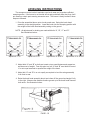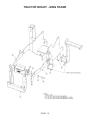
1
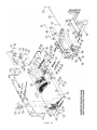
SWEEPER
ASSEMBLIES
NH TS100-135A
Current as of 6/11/07
PARTS LISTING WITH
MOUNTING AND OPERATING
INSTRUCTIONS
Tiger Corporation
3301 N. Louise Ave.
Sioux Falls, SD 57107
1-800-843-6849
1-605-336-7900
www.tiger-mowers.com
PAGE - 1
06020012
FORWARD
This manual contains information about the many features of the Tiger THS
Sweeper operator safety instructions, maintenance, and operating techniques. This
manual will also assist you in the proper break-in daily care, and troublleshooting of your
new sweeper.
We recommend that you read carefully the entire manual before operating the
unit. Also, time spent in becoming fully acquainted with ites performance features,
adjustments, and maintenance schedules will be repaid in a long and satisfactory life of
the equipment.
If at any time, you have a service problem with your sweeeper, contact your
dealer for your service and parts needs.
CONTENTS
FORWARD
2
TABLE OF CONTENTS
2
SAFETY PERCAUTIONS
3
OPERATIONAL SAFETY PRECAUTIONS
4
OPERATION
5
IMPORTANT INSTRUCTIONS
7
MOUNTING INSTRUCTIONS
8
LEVELING INSTRUCTIONS
10
SUPPORT YOKE ADJUSTMENT
12
BRUSH REPLACEMENT
13
MOTOR AND HUB REPLACEMENT
14
MAINTENANCE SCHEDULE
15
PARTS SECTION
16
PAGE - 2
SAFETY PRECAUTIONS
This symbol means: CAUTION ! Your safety is at rick !
– Any R.O.P.S. (roll over protective structure) should not be drilled, welded
on, or altered in any manner. Any alteration may reduce your protection.
– Do not bypass the tractor neutral safety swith. Jumping or bypassing can cause
tractor runaway.
– Do not allow any persons on the equipment except the operator.
– Loose clothing that can catch in moving parts should be avoided.
– Use the hand holds and step-plate provided when mounting and dismounting to
prevent injury.
– Keep safety decals clean and replace illegible and damaged decals.
– P.T.O. shield should be in pace at all times.
– Make a visual ilnspection of the tractor and mower components before attempting
ot start the unlit.
– be sure all bystanders are at a safe distance at all times.
– Do not start or operate any controls while standing along side the tractor. Be in the
tractor seat.
– Use the parking brake whenever dismounting from the tractor.
– P.T.O. lever should be disengaged before dismounting and when P.T.O. is not
being utilized.
– The mower switch should be in the “off” position when not in actual mowing or
sweeping position.
– Do not operate tractor in a closed building.
– Do not get off the tractor while still in motion.
– Use your seat belt if unit is equiped with R.O.P.S.
– Sudden uphill turns on steep slopes should be avoided.
PAGE - 3
This symbol means: CAUTION ! Your safety is at rick !
– Reduce speed when turning, taking curves, rough ground, or hillsides to reduce
chance of rollover.
– Always keep tractor in gear when traveling downhill to prevent runaway.
– When driving on a road, day or night, use lighting and markings required by local
laws.
– Lower equipment when not in use.
– Whenever stopping or leaving the unit you should: stop tractor and equipment,
lower equipment, be sure all motion stops, and remove key.
– Become familiar with the controls. Familiarilty of controls and functions increases
efficiency and decreases hazardous situations.
– Never allow children to operate the sweeper or mower.
OPERATIONAL SAFETY PRECAUTIONS
– Clear sweeping area of all foreign objects. Remove objects that coul cause
personal injury to the operator or others. Keep other sersons, children, and pets
ou of the work area.
– Always wear the proper apparel such as a long sleeve shirt buttoned to the cuffs
and safety glasses, goggles, or a face shield.
– Never operate the unit without all shields and hood in place.
– Plan your work ahead of time to help avoid accidents.
– Keep hands, feet, hair, and loose clothing away from engine, drive line,
brush, and other moving parts.
– If the unit is left unattended, even for a very short time, shut off engine, set parking
brake, and remove key.
_ Never sweep towards people, buildings, vehicles, or other objects that may be
damaged by flying debris.
– Dust and debris can be blown back into the operators face if consideration is not
given to wind direction. Wear the proper protective apparel.
PAGE - 4
OPERATION
Be sure the ball valves on the mower hydraulic tank are OPEN before starting the
tractor. Serious damage to the hydraulic system can occur if the valves are not OPEN.
For brush operation: open the high pressure valve located near the pressure port of
the pump and close the high pressure valve located near the electrical solenoid. This
procedure shuts off the oil flow to the mower.
For mower operation: close the high pressure valve located near the pressure port of
the pump and open the high pressure valve located near the electrical solenoid. This
procedure shuts off the oil flow to the brush.
Low brush speed and moderate ground speed will clean almost any hard surface of
all debris. Do not use high brush speeds or dust may be raised by the aggressive action
of the sweeper. Always remember the wind direction and plan your sweeping so it blows
at your back or to the direction that the brush head assembly is angled.
It is usually more effective to plan your sweeping for the days when it is overcast and
humid or on a day after it has rained. By planning in this manner, your dust will be kept
to a minimum.
To sweep gravel, use just enough brush spee to “roll” the gravel and not to throw it.
The sweeper is not a bulldozer!! Do not ram into piles trying to move them as a blade
would.
Remember, the sweeper sweeps with the tips of the broom, not wilth the sides like a
mop. Adjust the spring - chain assembly accordingly.
High brush speeds and low ground speeds are needed to do a good job in snow.
Start with about 3/4 throttle for wetter and deeper snow. This will help to keep the snow
from packing up inside the brush hood.
Just about any amount of snow can be thrown by the sweeper if enough patience
and consideration of the wind direction are used. In deep snow more than one pass may
have to be made to get down to a clean surface.
All Tiger Sweepers are equipped
with adjustable spring assemblies to
limit down pressure. Too often these
springs are removed and thrown away
or ignored. Proper down pressure
should be as pictured to the right.
Check and be sure you are using the
spring assembly. If it is lost or missing,
please order another from the dealer
or factory. If it is on, make sure you
understand and adjust it for poper
usage.
Brush on ground rotating
at normal operating speed
machine stationary.
When lifted, leaves a 2” to
4” clean spot on ground.
CORRECT SWEEPING PATTERN
PAGE - 5
It is very possible to cut brush life by 50% if the
frame is not level. Running an unlevel brush is
jast like throwingmoney out the window. The
small amount of time spent leveling a brush
before sweeping is paed back many times over
in longer brush life.
As a general rule brush level should be checked
every day before operating.
Uneven brush wear can also be caused by
discharging material to the same side of the
brush all the time. Flipping the brush core end for - end a couple of times during the course of
the brush life can help alleviate this.
Improper ground speed not only damages the
brush bur also cores, chains, sprockerts, drive
lines and even frames.
A rotary sweeper sweeps with the flicking action
of the bristle. The brush can sweep material up
to 1/2 the diameter of the brush. If the ground
speed of the vehicle is too fast the material
piles in front of the brush because it cannot be
discharged. This plow effect is caused by bull dozing with the sweeper instead of sweeping,
this will causes a side thrust on the brush, core
and frame components.
This sideward thrust causes the bristles to flex
against the steel ring holding them. Eventually
this flexing will break the bristles off at the ring.
Always sweep at a high enough brush speed
and low enough ground speed to effectively
discharge the material being swept.
PAGE - 6
TIGER SWEEPER
MODELS THS - 72CC & THS - 96C
IMPORTANT INSTRUCTIONS
1. Do not store sweeper polypropylene brushes in direct sunlight!
Direct sunlight will cause the bristles to deteriorate, causing the bristles to become
brittle. If the broom is to be stored for any length of time, store it in the shade,
inside, or cover the brush with a tarp to protect it from the sun.
2. Do not stor the sweeper power broom with the weight on the bristles!
Storing the sweeper power broom with the weight on the bristles will permanently
deform the bristles, destroying the sweeping effectiveness of the brush. Block the
brush up off the ground.
WITH PROPER CARE, YOUR POLYPROPYLENE BRUSH WILL GIVE LONG HOURS
OF TROUBLE FREE SERVICE, WITH EXCEPTIONALLY LOW WEAR ON BRUSH.
3. How do you get longer brush life?
Three factors can be controlled to give longer brush life. Brush down pressure,
brush level (uneven brush wear), ground speed.
BRUSH DOWN PRESSURE: more down pressure does not give a better sweep.
A brush gets its sweeping action by the flicking action of the bristles. This is most
effectively done with the tips of the bristles.
A brush sweeps with the bristle ends!
A mop works with the bristle sides!
PAGE - 7
When too much down pressure
is used the brush is working with
the sides of the bristles, not just
the tips. This mopping action not
only decreases the efficiency of
the brush but also causes 1/2” to
1 1/2” of bristle to be worn off at
once. Improper down pressure,
depending on the amount, can
decrease brush life 5% to 95%.
MOUNTING INSTRUCTIONS
Please rea and understand the instructions and schematics completely before
beginning assembly.
Parts and drawings may vary slightly due to the variety of tractor makes and models.
The mounting kit you receive should be correct for your application. If questions arise
please contact your local dealer or Tiger Service as needed.
Lay out all loose parts on a clean surface for easy identification. Part numbers and
descriptions can be found in this manual and other information received with ypur particular unit. Any shortages should be reported immediately.
The following assembly instructions are based on the assumption a Tiger mower is
already mounted on the tractor. Variations may occur in parts and assembly onto other
makes and models.
1. Mount the control valve stand within easy access of the operator (usually
mounted to the existing mower control valve stand).
2. Mount the two - spool control valve onto the control valve stand. Install the 1/2”
pressure and return hoses as shown on the schematic. This will maintain oil
containment until assembly is complete. Note: (If your tractor has a closed center
hydraulic system, it will be necessary to a closed center plug in the control valve).
Use teflon tape on all N.P.T. fitting and joints.
3. Mount the sweeper mounting frame onto the front of the tractor. Secure the frame
using lockwashers and capscrews provided. Be sure to use loctite on mount
bolts.
4. Position the swing assembly in front of the mounting frame as shown in the parts
breakdown section of this manual.
5. Turn the leveling bolts “A” and “B” all the way in, see figure A.
6. Remove the two 7/8” x 3” pins from the swing assembly mounting ears. Raise the
swing assembly and align the holes in the swing assembly mounting ears with the
holes inthe tractor frame mounting ears.
7. Insert 7/8” x 3” pins and secure with cotter pins.
8. Position the brush head asembly in front of the swing assembly as shown in the
parts breakdown section.
9. Remove the nuts and washers from the mounting bolts in the front plate of the
swing assembly.
10. Raise the back of the brush head frame and align the center bolt holes. Insert
the center hex head bolt and secure with the lockwasher and nut. Align the
slotted hole on each side of the center bolt, insert carriage bolts and secure with
flatwasher, lockwasher, and nut. These three brush head mounting bolts must
be left loose enough to allow for leveling.
PAGE - 8
11. The spring - chain assemblies are used to help support the weight of the brush
head assembly when in the sweeping position. Hook on spring to each of the
outside holes in the top plate of the brushhead upright. The chains are con
nected to the outside slots in the chain holder on the spring - chain assembly.
The spring - chain assemblies will require adjustment after installation is
complete.
12. Connect a 1/4” hydraulic hose from the lift cylinder to the left front port of the
control valve on the control valve stand. Note: (quick coupler end to valve).
13. Connect the 1/4” hydraulic hoses from the swing cylinder to the control valve.
The hoe connected to the swing cylinder at the rod end is connected to the right
front port of the control valve. The hose connected to the anchored end of the
swing cylinder is connected to the right rear port of the control valve. Note:
(quick coupler end to valve).
14. Connect the two 1” Hydraulic hoses to the tees on the brush head. Short hose
routes from pressure side of pump to top tee. Long hose routes from the bottom
tee to return side of solenoid valve. See brush feedline assembly schematic.
15. To connect the lift chain for the brush head, push the lift control forward and at
the same time pull out the lift bracket which is pinned to the lift cylinder of the
swing assembly. Drop the lift chain into the slot in the lift bracket. It may be
necessary to try two or three different chain links to fing the one that gives the
best and smoothest lift. Do not make the lift chain so short that the brush head
upright hits the lift bracket on the swing assembly when the brush head is raised.
16. You are now ready to level the brush head.
PAGE - 9
LEVELING INSTRUCTIONS
The sweeper must be leveled t maintain even brush wear and to produce efficient
sweeping action. If the broom is not leveled at first and periodically after that, then it will
put stress on certain parts causing excessive wear. The broom is easily leveled if these
steps are followed.
1. Drive the assembled broom onto a level paved area. Swing the brush head
assembly to the straight position. Lower the brush into the sweeping position with
the weitght of the brush head assembly resting on the ground.
NOTE: all adjustments for leveling are made with bolts “A”, “B”, “C” and “D”.
See illustrations below:
Adjust bolt “C” in
Adjust bolt “D” in
Adjust bolts “A” & “B” in
Adjust bolts “A” & “B” out
2. Adjust bolts “A” and “B” so both are turned out an equal distance and support an
equal amount of weight. From this point on, bolt “A” and “B” must both be turned
in or out equal amounts to equalize the weight of the head.
3. Adjust bolt “A” and “B” in or out equally as required to level the swing assembly
from front to rear.
4. Raise the brush head assembly about two inches off the ground and angle it fully
to the right. Measure the distance fromthe ground up to the brush head frame at
both ends. See illustration below:
PAGE - 10
LEVELING INSTRUCTIONS CONTINUED
Make a note of the measurements. Swing the brush head assembly to the left and
take the same measurements. If the measurements are not equal, refer to previous
leveling steps and illustrations for adjustments.
5. After leveling, tighten the brush head mounting bolts E, F and G
PAGE - 11
SUPPORT YOKE ADJUSTMENT
NOTE: This section applies only to units with serial number 75146 and above. Units
with serial number below 75146 do not have adjustable support yokes. Before operating
the sweeper the brush head frame support yokes should be checked and if necessary
adjusted as follows:
1. Loosen the two 5/8” carriage bolts in each of the support yokes as shown in the
figure below.
2. Swing the brush head assembly fully to the right.
3. Snug the right support yoke around the brush head tube and tighten the two 5/8”
bolts.
4. Swing the brush head assembly fully to the left.
5. Snug the left support yoke around the brush head tube and tighten the two 5/8”
bolts.
6. Check the brush head assembly for proper leveling. It may be necessary to adjust
the support yoke up or down in order to achieve correct leveling of the brush
head assembly.
PAGE - 12
BRUSH REPLACEMENT
1. Disconnect the two hydraulic hoses at both motors. IMPORTANT: Tape over the
ends of the hydraulic hoses and the hydraulic motor ports to prevent
contamination of the hydraulic system.
2. Remove the four bolts holding the hood in place. Lift the hood off the brush and
set aside.
3. Remove the two carriage bolts in the motor housing at both ends of the brush
head assembly.
4. Slide the brush assembly out of the brush head frame.
5. Place a couple of blocks at either end of the brush assembly. The blocks must be
high enough to prevent the hydraulic motor or the hydraulic motor housing from
hitting the ground when the brush assembly is stood up on end.
6. Place one block on each side of the hydraulic motor housing. Stand the brush
assembly up on end.
7. Remove the end ring from the top end of the brush assembly.
8. Remove the old sections from the core. Follow the instructions enclosed with the
new sections to fill the core.
9. With the new sections on the core, replace the end ring and secure with the four
allen head screws.
10. Lay the brush assembly on its side.
11. Slide the brush assembly into the brush head frame. Replace the two carriage
bolts in each motor housing.
12. To make sure the brush is straight in the brush head frame, measure the dis
tance from the center of the brush head frame tube. Measure this distance on
both sides of the brush head assembly. If these measurements are not the
same, slide either end in or out until both measurements are equal. Tighten all
bolts.
13. Replace the hood and secure with the four bolts. Adjust the front of the hood so
it is even across the brush.
14. Remove the tape on the hydraulic motors and hoses. Reconnect the hoses to
the motors.
PAGE - 13
MOTOR AND HUB REPLACEMENT
1. Disconnect the two hydraulic hoses at both motors. IMPORTANT: Tape over the
ends of the hydraulic hoses and the hydraulic motor ports to prevent
contamination of the hydraulic system.
2. Remove the four bolts holding the hood in place. Lift the hood off the brush and
set aside.
3. Remove the two carriage bolts in the motor housing at both ends of the brush
head assembly.
4. Slide the brush assembly out of the brush head frame.
5. Remove the end ring from the end with the bad motor.
6. Remove the first few sections to expose the motor and hub inside the core.
7. To remove the motor from the core, remove the hairpin and then the nut on the
end of the motor shaft which holds teh motor to the hub. Pull motor out of the core
and make sure the key does not drop out of the shaft.
8. If the motor must be replaced, remove the motor from the housing and place the
new one in position.
9. If the hub must be replaced, remove the four bolts which hold it to the core plate
and replace it with the new hub.
10. With the new hub and / or motor in place. Slide the motor into the housing,
throught the core and into the hub. Replace the motor shaft nut and tighten.
Secure with hairpin.
11. Replace the sections in the same order as they were removed.
12. Replace the end ring and secure with the four allen head bolts.
13. Slid the brush assembly into the brush head frame. Replace the two carriage
bolts in each motor housing.
14. To make sure the brush is straight in the brush head frame, measure the dis
tance from the center of the brush head frame tube. Measure this distance on
both sides of the brush head assembly. If these measurements are not the
same, slide either end in or out until both measurements are equal. Tighten all
bolts.
15. Replace the hood and secure with the four bolts. Adjust the front of the hood so
it is even across the brush.
16. Remove the tape on the hydraulic motors and hoses. Reconnect the hoses to
the motors.
PAGE - 14
PAGE - 15
TRACTOR MOUNT - MAIN FRAME
PAGE - 16
TRACTOR MOUNT - MAIN FRAME
ITEM
PART NO.
QTY.
DESCRIPTION
1
2
2
4
5
6
7
8
9
10
34857
06410443
06410442
06430049
41644
21735
24879
21843
33880
06400165
1
1
1
4
1
4
4
4
4
4
MTG,THS
MNT,LH,SWPR,CNH,TSA
MNT,RH,SWPR,CNH,TSA
SPACER,2.00x1.00x3.34
PLATE,ATTACHING
CAPSCREW,1/2 x 2 1/2,NC
CAPSCREW , 20MM x 65MM(2.5 PITCH)
CAPSCREW 3/4” x 6” NC
FLATWASHER, 3/4”,GR 8, SAE
SPACER,COOLER,FRONT
PAGE - 17
PAGE - 18
PAGE - 19
PAGE - 20